WO2011030698A1 - Dispositif de contrôle des environs d'un véhicule - Google Patents
Dispositif de contrôle des environs d'un véhicule Download PDFInfo
- Publication number
- WO2011030698A1 WO2011030698A1 PCT/JP2010/064864 JP2010064864W WO2011030698A1 WO 2011030698 A1 WO2011030698 A1 WO 2011030698A1 JP 2010064864 W JP2010064864 W JP 2010064864W WO 2011030698 A1 WO2011030698 A1 WO 2011030698A1
- Authority
- WO
- WIPO (PCT)
- Prior art keywords
- image
- vehicle
- display screen
- monitoring device
- periphery monitoring
- Prior art date
Links
- 238000012544 monitoring process Methods 0.000 title claims description 13
- 238000012806 monitoring device Methods 0.000 claims description 27
- 238000003384 imaging method Methods 0.000 claims description 10
- 230000001154 acute effect Effects 0.000 claims description 6
- 230000001131 transforming effect Effects 0.000 claims description 3
- 238000012545 processing Methods 0.000 description 14
- 238000012937 correction Methods 0.000 description 12
- 230000002441 reversible effect Effects 0.000 description 11
- 238000000034 method Methods 0.000 description 10
- 230000008569 process Effects 0.000 description 10
- 238000012986 modification Methods 0.000 description 5
- 230000004048 modification Effects 0.000 description 5
- 238000006243 chemical reaction Methods 0.000 description 3
- 230000008859 change Effects 0.000 description 2
- 238000010008 shearing Methods 0.000 description 2
- 230000009466 transformation Effects 0.000 description 2
- 208000020401 Depressive disease Diseases 0.000 description 1
- 238000013459 approach Methods 0.000 description 1
- 238000004891 communication Methods 0.000 description 1
- 230000004300 dark adaptation Effects 0.000 description 1
- 230000003247 decreasing effect Effects 0.000 description 1
- 238000010586 diagram Methods 0.000 description 1
- 238000005286 illumination Methods 0.000 description 1
- 230000006872 improvement Effects 0.000 description 1
- 230000004301 light adaptation Effects 0.000 description 1
- 230000003287 optical effect Effects 0.000 description 1
- 238000005192 partition Methods 0.000 description 1
- 230000002093 peripheral effect Effects 0.000 description 1
- 230000004044 response Effects 0.000 description 1
- 230000035945 sensitivity Effects 0.000 description 1
- 230000000007 visual effect Effects 0.000 description 1
Images


Classifications
-
- H—ELECTRICITY
- H04—ELECTRIC COMMUNICATION TECHNIQUE
- H04N—PICTORIAL COMMUNICATION, e.g. TELEVISION
- H04N7/00—Television systems
- H04N7/18—Closed-circuit television [CCTV] systems, i.e. systems in which the video signal is not broadcast
-
- B—PERFORMING OPERATIONS; TRANSPORTING
- B60—VEHICLES IN GENERAL
- B60R—VEHICLES, VEHICLE FITTINGS, OR VEHICLE PARTS, NOT OTHERWISE PROVIDED FOR
- B60R1/00—Optical viewing arrangements; Real-time viewing arrangements for drivers or passengers using optical image capturing systems, e.g. cameras or video systems specially adapted for use in or on vehicles
- B60R1/20—Real-time viewing arrangements for drivers or passengers using optical image capturing systems, e.g. cameras or video systems specially adapted for use in or on vehicles
- B60R1/22—Real-time viewing arrangements for drivers or passengers using optical image capturing systems, e.g. cameras or video systems specially adapted for use in or on vehicles for viewing an area outside the vehicle, e.g. the exterior of the vehicle
- B60R1/23—Real-time viewing arrangements for drivers or passengers using optical image capturing systems, e.g. cameras or video systems specially adapted for use in or on vehicles for viewing an area outside the vehicle, e.g. the exterior of the vehicle with a predetermined field of view
- B60R1/26—Real-time viewing arrangements for drivers or passengers using optical image capturing systems, e.g. cameras or video systems specially adapted for use in or on vehicles for viewing an area outside the vehicle, e.g. the exterior of the vehicle with a predetermined field of view to the rear of the vehicle
-
- B—PERFORMING OPERATIONS; TRANSPORTING
- B60—VEHICLES IN GENERAL
- B60R—VEHICLES, VEHICLE FITTINGS, OR VEHICLE PARTS, NOT OTHERWISE PROVIDED FOR
- B60R2300/00—Details of viewing arrangements using cameras and displays, specially adapted for use in a vehicle
- B60R2300/30—Details of viewing arrangements using cameras and displays, specially adapted for use in a vehicle characterised by the type of image processing
- B60R2300/303—Details of viewing arrangements using cameras and displays, specially adapted for use in a vehicle characterised by the type of image processing using joined images, e.g. multiple camera images
-
- B—PERFORMING OPERATIONS; TRANSPORTING
- B60—VEHICLES IN GENERAL
- B60R—VEHICLES, VEHICLE FITTINGS, OR VEHICLE PARTS, NOT OTHERWISE PROVIDED FOR
- B60R2300/00—Details of viewing arrangements using cameras and displays, specially adapted for use in a vehicle
- B60R2300/80—Details of viewing arrangements using cameras and displays, specially adapted for use in a vehicle characterised by the intended use of the viewing arrangement
- B60R2300/806—Details of viewing arrangements using cameras and displays, specially adapted for use in a vehicle characterised by the intended use of the viewing arrangement for aiding parking
Definitions
- the present invention relates to a vehicle periphery monitoring device that performs a predetermined process on a captured image of a vehicle periphery captured by a camera and displays the image on a display device in a vehicle interior.
- Patent Document 1 In order to solve the above-described problems, for example, a distortion correction process described in Patent Document 1 is known.
- the driver's visibility (visibility) for the displayed image is improved. For example, by displaying an image (video) around a vehicle taken with a camera having a wide angle of view (for example, a horizontal angle of 160 degrees or more) as a single image, a wide area can be visually recognized on the display screen. The presence or absence of pedestrians can be recognized.
- a wide angle of view for example, a horizontal angle of 160 degrees or more
- the present invention has been made in view of the above problems, and an object of the present invention is to accurately present to the driver the situation where obstacles or people around the vehicle are present.
- the technical means taken in the present invention includes at least one imaging means for photographing the periphery of the vehicle, a first image based on a photographed image photographed by the imaging means, A second image having the image content of the first image and a continuous image content is generated, and a display screen in which the first image and the second image are arranged in a horizontal direction with a predetermined gap is generated.
- the image processing apparatus includes screen generation means and display means for displaying the display screen generated by the screen generation means.
- the first image and the second image are images that display the periphery of the vehicle from a viewpoint that forms an acute angle with respect to the horizontal direction.
- the screen generation means generates the second image continuous in the left direction of the first image and the second image continuous in the right direction of the first image, and 2 It is more preferable to generate a display screen in which the two second images are arranged in the horizontal direction of the first image.
- the first image has a rectangular shape
- the second image has a parallelogram shape other than a rectangle
- the first image and the second image are displayed on the display screen. It is more preferable that adjacent sides are parallel to each other.
- the screen generation means generates the second image by transforming at least a part of the photographed image into a parallelogram shape.
- the screen generating means increases the brightness of the second image when it is determined that the night.
- the screen generation means convert the second image into monochrome when it is determined that the night.
- the screen generating means reverses the second image negatively and positively when it is determined that it is nighttime.
- the technical means taken in the present invention for example, it is easy to distinguish between the rear side and the side, and it is possible to accurately present to the driver the situation where obstacles or people around the vehicle exist.
- FIG. 1 is a schematic view of a vehicle 100 including a vehicle periphery monitoring device 50 according to the present invention.
- the vehicle 100 is provided with a rear camera 11 that captures a scene behind the vehicle 100.
- the rear camera 11 is provided at the rear portion of the vehicle 100 and is provided so as to face slightly downward with respect to the horizontal direction. That is, the optical axis of the rear camera 11 forms an acute angle with respect to the road surface on which the vehicle 100 exists.
- the rear camera 11 is installed with a depression angle of about 30 degrees toward the rear of the vehicle 100, and can photograph a region up to about 8 m behind the vehicle 100.
- the rear camera 11 is a digital camera that incorporates an image sensor such as a CCD (charge coupled device) or a CIS (CMOS image sensor) and outputs information captured by the image sensor in real time as moving image information.
- the rear camera 11 is preferably configured using, for example, a wide-angle lens (for example, an angle of view of 160 ° or more) or a fish-eye lens.
- the vehicle 100 includes an electronic control unit 20 illustrated in FIG.
- the electronic control unit 20 is composed of, for example, a microcomputer having a ROM and a RAM.
- a captured image (video) captured by the rear camera 11 is transmitted to the electronic control unit 20 as described later, and after predetermined processing is performed by the electronic control unit 20, a monitor 200 in the vehicle interior shown in FIG. (Display means).
- the monitor 200 is also used as a display device for the navigation system.
- the vehicle 100 is provided with a vehicle speed sensor that detects the speed of the vehicle 100 (not shown).
- the wheel pulse detected by the vehicle speed sensor and the vehicle speed are transmitted to the electronic control unit 20 by a predetermined communication means.
- FIG. 2 shows the vehicle periphery monitoring device 50, and the captured image captured by the rear camera 11 is transmitted to the electronic control unit 20.
- the electronic control unit 20 includes a screen generation unit 21 and an output unit 22.
- the screen generation unit 21 generates a display screen based on the captured image captured by the rear camera 11.
- the generated display screen is transmitted from the screen generation unit 21 to the monitor 200 via the output unit 22 and displayed on the monitor 200.
- FIG. 3 is a diagram showing a display screen 210 displayed on the monitor 200 by the vehicle periphery monitoring device 50 according to the present invention.
- the display screen is switched to the display screen shown in FIG.
- the captured image captured by the rear camera 11 includes a central image 211, a right image 212 having a substantially parallelogram shape arranged on the right side of the central image 211, and a substantially arranged image on the left side of the central image 211. It is displayed as a parallelogram-shaped left image 213.
- the center image 211 and the right image 212 and the center image 211 and the left image 213 are partitioned by a dividing line 250.
- a predetermined gap is provided between the central image 211 and the right image 212 and between the central image 211 and the left image 213. In this way, it is easy to distinguish between the rear and the side by dividing and displaying between the center image 211 and the right image 212 and between the center image 211 and the left image 213.
- the center image 211 and the right image 212 have continuous image contents (maintaining continuity of the image contents) with the dividing line 250 interposed therebetween. Further, adjacent sides of the center image 211 and the right image 212 are parallel to each other. The same applies to the center image 211 and the left image 213.
- the generation of the center image 211, the right image 212, and the left image 213 and the arrangement of these images on the display screen are due to the function of the screen generation unit 21.
- the image content is continuous means that the center image 211 and the right image 212 (or the left image 213) are connected.
- the image values on the opposite sides coincide (or are continuous). Even if the image values on the opposite sides of the central image 211 and the right image 212 (or the left image 213) do not match (or continue), the central image 211 and the right image 212 (or the left image 213)
- the image content is said to be continuous.
- the central image 211 and the right image 212 match (or continue)
- the central image 211 and the right image 212 or This is a case where the left image 213) is masked with a dividing line having a predetermined width on the boundary between the center image 211 and the right image 212 (left image 213) when arranged in the horizontal direction without a gap.
- the display screen 210 by the vehicle periphery monitoring device 50 in this embodiment is such that the rear side of the vehicle and its left and right conditions are visually recognized as if it were a three-sided mirror holding the left and right mirrors at a predetermined angle with respect to the central mirror.
- the central image 211 is an image in the traveling direction (front) when the steering wheel is substantially straight, and the right image 212 and the left image 213 have the left and right peripheral situations of the content displayed by the central image 211, respectively. Is displayed.
- the positional relationship among the central image 211, the right image 212, and the left image 213 corresponds to the actual positional relationship
- the front image (the central image 211) is displayed in a rectangle, and the image corresponds to the left and right of the front image.
- (Right image 212, Left image 213) are displayed in a parallelogram shape. Therefore, it is possible to confirm the safety of a wide range behind the vehicle 100, and to easily distinguish whether there are obstacles or people in the rear or the side.
- a figure simulating the vehicle 100 and an icon 260 composed of two triangles and a trapezoid are displayed. This allows the driver to recognize where the center image 211, the right image 212, and the left image 213 are displayed around the vehicle 100.
- a warning text is displayed at the bottom of the display screen 210.
- an index line 300 serving as an index when the driver is driving is superimposed and displayed.
- an index line extending in the horizontal direction of the screen indicates a predicted position from the rear end of the vehicle 100.
- the index lines extending in the horizontal direction of the screen are index lines indicating positions of 50 cm, 1 m, and 3 m from the rear end of the vehicle 100 from the lower side of the screen, respectively.
- two left and right lines extending substantially in the vertical direction of the display screen 210 indicate the width of the vehicle 100 or a width obtained by increasing or decreasing a predetermined value to the width of the vehicle 100. is there.
- the index line 300 may be a fixed line or may be linked to the steering angle.
- the index line 300 can be displayed in three dimensions with at least one of a shadow part and a side part. According to this, it is possible to make the driver recognize that the index line 300 is along the road surface displayed in the central image 211.
- FIG. 4 is a real image of a display screen displayed by the vehicle periphery monitoring device according to the embodiment of the present invention.
- the screen generation unit 21 first performs distortion correction processing described in, for example, Japanese Patent Application Laid-Open No. 2009-12652 on the captured image captured by the rear camera 11.
- the outline of the distortion correction processing described in Japanese Patent Application Laid-Open No. 2009-12652 will be described in the case of applying to the present embodiment.
- the first axis (the horizontal direction of the display screen) is substantially fixed with respect to the captured image, while the second axis A process of enlarging the (display screen vertical direction) direction with a non-linearly increasing enlargement ratio depending on the distance from the second axis is performed.
- the first axis direction is fixed, and the second axis direction is enlarged at an enlargement factor ⁇ .
- This enlargement ratio increases as the distance from the second axis increases, that is, as the size of the display screen horizontal coordinate (the absolute value of the display screen horizontal coordinate) increases.
- an image after the distortion correction processing is performed on the captured image captured by the rear camera 11 is denoted as IM0.
- the origin O is the center of the captured image (image sensor).
- the center image 211, the right image 212, and the left image 213 are generated as follows.
- IM0 a rectangular area shown in FIG. 6 (b) having an x coordinate of ⁇ t ⁇ x ⁇ t (t> 0) and a y coordinate of ⁇ H / 2 ⁇ y ⁇ H / 2 (H> 0).
- IM1 that is the center image 211.
- the central image 211 is a partial image (IM1) of IM0 having a rectangular shape with a vertical side length of H and a horizontal side length of 2t, as shown in FIG. 6B.
- the right image 212 is generated as follows. First, as shown in FIG. 6B, the IM2 that is the region of the IM0 where the x coordinate is t ⁇ x ⁇ t + W is specified. That is, IM2 is a partial image of IM0 and is adjacent to IM1 in IM0. Therefore, IM2 is a rectangle having a vertical side length of H and a horizontal side length of W as shown in FIG. Here, IM2 is deformed to generate IM2 ′. This image deformation means that the pixel value at the coordinate value (X0, Y0) in IM2 is set to the pixel value at the coordinate value (X1, Y1) in IM2 ′.
- the right image 212 becomes an image in which the image is lifted by shearing in the y-axis direction as it goes to the right side (the direction in which the x coordinate increases) with respect to the original image IM2 (IM0).
- IM0 the original image IM2
- the left image 213 is also generated as follows.
- the IM3 that is the region of the IM0 whose x coordinate is tW ⁇ x ⁇ ⁇ t is specified. That is, IM3 is a partial image of IM0 and is adjacent to IM1 in IM0.
- IM3 is a rectangle having a vertical side length of H and a horizontal side length of W as shown in FIG.
- the image of IM3 is deformed to generate IM3 ′.
- This image deformation means that the pixel value at the coordinate value (X0, Y0) in IM3 is set to p, and the pixel value at the coordinate value (X1, Y1) in IM3 ′ is set to p.
- the left image 213 becomes an image in which the image is lifted by shearing in the y-axis direction as it goes to the left side (the direction in which the x coordinate becomes smaller) with respect to the original image IM3 (IM0).
- IM0 the original image IM3
- the screen generation unit 21 arranges the right image 212 and the left image 213 generated in this way on the right and left of the central image 211, respectively, and generates the display screen 210 of FIGS.
- the display screen shown in FIGS. 3 and 4 is switched to 210. That is, the display screen 210 shown in FIG. 3 and FIG. 4 is a display screen including an image (display image at stop) for displaying when the vehicle 100 is stopped.
- the display screen 210 shown in FIG. 3 and FIG. 4 is a display screen including an image (display image at stop) for displaying when the vehicle 100 is stopped.
- the vehicle periphery monitoring device shifts to a standby mode in which it waits without performing display for periphery monitoring.
- a standby mode for example, a navigation screen is displayed.
- the center image 211, the right image 212, and the left image 213 are display images when stopped.
- FIG. 5 shows a display screen including an image displayed when the vehicle 100 is not stopped (non-stop display image) when the vehicle 100 starts moving backward (running or moving) after confirming safety.
- the central image 211 is a non-stop display image.
- the image generation unit 21 generates a display screen including a display image when stopped and a display screen including a display image when not stopped.
- the central image 211, the right image 212, and the left image 213 are display images when stopped, and the central image 211 is a non-stop display image, the periphery of the vehicle 100 on which the non-stop display image is displayed.
- the area is narrower than the area around the vehicle 100 where the display image is displayed when the vehicle is stopped. That is, the stop-time display image is a wide-angle image, and the non-stop-time display image is a narrow-angle image.
- the non-stop display image is a partial image of the stop display image.
- the display screen including the non-stop display image is the display screen 220 shown in FIG.
- the central image 211 is enlarged and displayed by the amount that the right image 212 and the left image 213 are not displayed.
- the central image 211 may not be enlarged, and an image (only the central image 211) that does not display the right image 212 and the left image 213 from the display screens of FIGS. 3 and 4 may be used. .
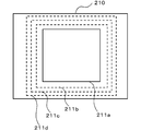
- the display When switching from the display screen including the display image at the time of stop (display screen 210) to the display screen including the display image at the time of non-stop (display screen 220), the display may be immediately switched to the enlarged display of the central image 211.
- switching is performed as follows. First, the right image 212 and the left image 213 are deleted from the display screen 210. Thereafter, as schematically illustrated in FIG. 7, the central image 211a (the central image 211 immediately after the right image 212 and the left image 213 are deleted) is gradually enlarged to the central image 211b, the central image 211c, and the central image 211d. To go. At this time, the image may be continuously expanded or may be expanded stepwise (stepwise). By presenting the process of switching the display screen to the driver in this way, the driver recognizes where the display screen (image) after switching corresponds (corresponds) to the display screen (image) before switching, Easy to understand.
- the reverse start of the vehicle 100 is, for example, a wheel pulse from a vehicle speed sensor as a movement distance detecting means for detecting a movement distance when the speed of the vehicle 100 detected by the vehicle speed sensor is greater than a predetermined speed. This is when the electronic control unit 20 determines that the vehicle has traveled a predetermined distance from the stop state using the accumulated number.
- the vehicle periphery monitoring device 50 stands by. For example, a navigation screen is displayed.
- the vehicle may be returned to the display screen (display screen 210) including the display image when stopped.
- the driver may be notified by sound or voice of switching to the display screen including the display image at the time of stop.
- the driver can monitor the surroundings appropriately according to the situation by automatically switching to an appropriate range of images instead of an image with a wider angle of view than necessary when traveling backwards. It becomes.
- the driver does not need to perform a switch operation and is not troublesome.
- the vehicle 100 may not be provided with illumination for illuminating the areas of the right image 212 and the left image 213. Therefore, when it is determined at night (or when the vehicle 100 is in a place with low illuminance such as indoors), only the right image 212 and the left image 213 of the center image 211, the right image 212, and the left image 213 are corrected for luminance. It is preferable to improve visibility by adding processing to display brightly. At this time, determination at night may be performed based on luminance information of the entire captured image.
- the right image 212 or the partial image that is the original of the right image 212 is subjected to luminance correction processing based on the luminance information of the right image 212 or the partial image (IM2) that is the original of the right image 212.
- the luminance correction processing of the left image 213 may be performed.
- the determination at night may be based on time information instead of luminance information, or may be based on lighting of a headlight or a width lamp by a driver.
- the electronic control unit 20 is provided separately from the rear camera 11, but is not limited to this, and the electronic control unit 20 may be provided in the rear camera 11 and integrated.
- the present invention can of course be applied when the vehicle 100 moves forward.
- a front camera is provided instead of the rear camera 11, and the shift position may be determined as a forward position (D position or the like) instead of the reverse position.
- the captured image from one rear camera 11 is divided and displayed in the center image 211, the right image 212, and the left image 213, but images captured by a plurality of cameras may be used.
- a right side camera that captures the rear right side of the vehicle 100 and a left side camera that captures the rear left side of the vehicle 100 are displayed.
- the captured image of the rear camera 11 is displayed in the central image 211, and the right side
- the video of the camera may be displayed on the right image 212, and the video of the left side camera may be displayed on the left image 213.
- the present invention is not limited to dividing images from one camera, and when displaying images from a plurality of cameras, the positional relationship of each image and the position and direction relationship with the vehicle can be accurately presented to the driver. it can.
- the imaging ranges of the rear camera 11, the right side camera, and the left side camera may or may not overlap.
- the present invention can also be applied to the case where the front camera monitors the front periphery of the vehicle 100.
- the present invention can also be applied to the case where the side periphery of the vehicle 100 is monitored by a side camera that monitors the side of the vehicle 100.
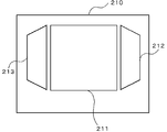
- the right image 212 and the left image 213 have a parallelogram shape in which the vertical side that is not on the central image 211 side is higher than the central image 211. Modifications thereof are shown in FIGS. In FIG. 8, the right image 212 and the left image 213 are rectangular. In FIG. 9, the right image 212 and the left image 213 are trapezoidal. In FIG. 10, the right image 212 and the left image 213 have parallelogram shapes such that the vertical sides of the right image 212 and the left image 213 that are not on the center image 211 side are below the center image 211. In addition, the right image 212 and the left image 213 can be triangular or polygonal.
- the right image 212 and the left image 213 may be subjected to the image deformation as described above according to the shape displayed on the display screen, or may be performed according to the shape displayed on the display screen without performing the image deformation. An image cut out from a specific image may be used.
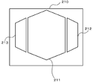
- the central image 211 has a rectangular shape, but is not limited thereto, and may be a hexagon as shown in FIG. 11 or other polygons.
- the adjacent sides of the center image 211 and the right image 212 are parallel to each other and have a predetermined gap.
- the image content is continuous across the gap (partition line).
- the center image 211, the left image 213, and the right image 212 are displayed while the vehicle 100 is stopped, and only the center image 211 is displayed while the vehicle 100 is running.
- An image of a camera with an angle (for example, 160 °) is displayed, and an image with a narrow angle of view (for example, equivalent to about 130 °) obtained by extracting a part (partial image) from the image with the wide angle of view during driving May be displayed.
- two cameras with a wide angle of view and two cameras with a narrow angle of view may be provided, and the display may be switched in the same manner.
- a rear camera 11 and a right side camera that captures the rear right side of the vehicle 100 and an image of the left side camera that captures the rear left side of the vehicle 100 are displayed. At least one of the images of the camera and the left side camera may be displayed, and only the image of the rear camera 11 may be displayed during traveling.
- the right image 212 and the left image 213 are brightly displayed by performing luminance correction processing.
- Image processing that is reversed, reversed (negative / positive reversed), or reversed after monochrome (negative / positive reversed) may be performed.
- monochrome By converting to monochrome, an image with the highest possible brightness can be obtained even when the subject is dark. Further, by reversing, a bright image can be obtained when the subject is dark.
- the sensitivity adjustment of the human eye is more rapid with light adaptation than with dark adaptation, and a better response is obtained with a brighter index for lens focus adjustment. It is also preferable from the viewpoint of engineering.
- a color image is negative-positive-inverted, the color is greatly deviated from the actual color. Therefore, when the photographed image is a color image, it is desirable to reverse the grayscale image negative-positive in order to reduce discomfort.
- the wide-angle image (display screen 210) including the display image at the time of stoppage is returned to the display screen (display screen 210), but once the display state of the display screen including the narrow-angle image (non-stop display image) is obtained, the vehicle 100 is then stopped.
- the display screen (display screen 210 shown in FIGS. 3 and 4) including a wide-angle image (display image at the time of stop) may not be returned.
- the operation mode of the former (this embodiment) and the operation mode of the latter (another embodiment) may be switchable by a driver using a switch.
- the captured image captured by the camera is used without changing the viewpoint (change of viewpoint position and line-of-sight direction).
- the present invention is not limited to this, and the captured image converted from the viewpoint is used. May be.
- a viewpoint conversion image processed to increase or decrease the depression angle of the captured image within the range of the gaze direction that forms an acute angle with respect to the horizontal direction an image that displays the periphery of the vehicle having an acute depression angle
- a viewpoint-converted image obtained by combining these processes or a viewpoint-converted image obtained by combining these processes may be used.
- the present invention can be used for a vehicle periphery monitoring device that performs a predetermined process on a captured image of a vehicle periphery captured by a camera and displays the image on a display device in a vehicle interior.
Landscapes
- Engineering & Computer Science (AREA)
- Multimedia (AREA)
- Signal Processing (AREA)
- Mechanical Engineering (AREA)
- Closed-Circuit Television Systems (AREA)
Abstract
Priority Applications (4)
| Application Number | Priority Date | Filing Date | Title |
|---|---|---|---|
| JP2011530810A JP5598731B2 (ja) | 2009-09-11 | 2010-09-01 | 車両周辺監視装置 |
| US13/390,737 US20120154589A1 (en) | 2009-09-11 | 2010-09-01 | Vehicle surrounding monitor apparatus |
| EP10815295.0A EP2476587B1 (fr) | 2009-09-11 | 2010-09-01 | Dispositif de contrôle des environs d'un véhicule |
| CN2010800388642A CN102481875A (zh) | 2009-09-11 | 2010-09-01 | 车辆周围监视装置 |
Applications Claiming Priority (2)
| Application Number | Priority Date | Filing Date | Title |
|---|---|---|---|
| JP2009-210052 | 2009-09-11 | ||
| JP2009210052 | 2009-09-11 |
Publications (1)
| Publication Number | Publication Date |
|---|---|
| WO2011030698A1 true WO2011030698A1 (fr) | 2011-03-17 |
Family
ID=43732371
Family Applications (1)
| Application Number | Title | Priority Date | Filing Date |
|---|---|---|---|
| PCT/JP2010/064864 WO2011030698A1 (fr) | 2009-09-11 | 2010-09-01 | Dispositif de contrôle des environs d'un véhicule |
Country Status (5)
| Country | Link |
|---|---|
| US (1) | US20120154589A1 (fr) |
| EP (1) | EP2476587B1 (fr) |
| JP (1) | JP5598731B2 (fr) |
| CN (1) | CN102481875A (fr) |
| WO (1) | WO2011030698A1 (fr) |
Cited By (4)
| Publication number | Priority date | Publication date | Assignee | Title |
|---|---|---|---|---|
| EP2551817A3 (fr) * | 2011-07-28 | 2013-12-18 | Robert Bosch Gmbh | Système de caméra de rétroviseur pour véhicule et procédé |
| EP2805183A1 (fr) * | 2012-01-19 | 2014-11-26 | Robert Bosch GmbH | Procédé et dispositif de visualisation de l'environnement d'un véhicule |
| US20150022665A1 (en) * | 2012-02-22 | 2015-01-22 | Magna Electronics Inc. | Vehicle camera system with image manipulation |
| JP2018160748A (ja) * | 2017-03-22 | 2018-10-11 | トヨタ自動車株式会社 | 車両用表示制御装置 |
Families Citing this family (10)
| Publication number | Priority date | Publication date | Assignee | Title |
|---|---|---|---|---|
| DE102011121616A1 (de) * | 2011-12-20 | 2013-06-20 | Audi Ag | Verfahren zur Ansteuerung einerAnzeigeeinrichtung eines Kraftfahrzeugs |
| US9242602B2 (en) * | 2012-08-27 | 2016-01-26 | Fotonation Limited | Rearview imaging systems for vehicle |
| DE102014201161A1 (de) * | 2014-01-23 | 2015-07-23 | Robert Bosch Gmbh | Verfahren und Vorrichtung zum Ermitteln eines blinden Bereichs einer Kamera |
| DE102015216907A1 (de) * | 2015-09-03 | 2017-03-09 | Robert Bosch Gmbh | Digitaler Rückspiegel |
| CN108725319B (zh) * | 2017-10-31 | 2021-05-04 | 无锡职业技术学院 | 一种影像式倒车指导方法 |
| CN111480175A (zh) * | 2018-01-05 | 2020-07-31 | 沃尔沃卡车集团 | 具有显示与广角图像的至少一个失真部分邻接的广角图像的未失真部分的显示器的相机监视系统 |
| FR3079180B1 (fr) * | 2018-03-22 | 2020-03-13 | Renault S.A.S. | Systeme de vision panoramique affichee sur un ecran portrait |
| CN110949255A (zh) * | 2019-12-23 | 2020-04-03 | 深圳市豪恩汽车电子装备股份有限公司 | 机动车辅助泊车装置及方法 |
| CN110949257A (zh) * | 2019-12-23 | 2020-04-03 | 深圳市豪恩汽车电子装备股份有限公司 | 机动车辅助泊车装置及方法 |
| CN110949256A (zh) * | 2019-12-23 | 2020-04-03 | 深圳市豪恩汽车电子装备股份有限公司 | 机动车辅助泊车装置及方法 |
Citations (6)
| Publication number | Priority date | Publication date | Assignee | Title |
|---|---|---|---|---|
| JPH11243538A (ja) * | 1998-02-25 | 1999-09-07 | Nissan Motor Co Ltd | 車両用視認装置 |
| JP2003061084A (ja) * | 2001-08-09 | 2003-02-28 | Matsushita Electric Ind Co Ltd | 運転支援表示装置 |
| JP2003255925A (ja) * | 2002-03-05 | 2003-09-10 | Matsushita Electric Ind Co Ltd | 画像表示制御装置 |
| JP2005184523A (ja) * | 2003-12-19 | 2005-07-07 | Matsushita Electric Ind Co Ltd | 車載監視カメラ装置 |
| JP2006137383A (ja) * | 2004-11-15 | 2006-06-01 | Niles Co Ltd | 車両用撮像装置 |
| JP2009012652A (ja) | 2007-07-05 | 2009-01-22 | Aisin Seiki Co Ltd | 車両の周辺監視装置 |
Family Cites Families (10)
| Publication number | Priority date | Publication date | Assignee | Title |
|---|---|---|---|---|
| US6587130B1 (en) * | 1998-11-09 | 2003-07-01 | Yazaki Corporation | Multi-function switch device |
| CN2424965Y (zh) * | 2000-03-01 | 2001-03-28 | 张士杰 | 倒车安全监视装置 |
| JP3866109B2 (ja) * | 2002-01-16 | 2007-01-10 | 富士通テン株式会社 | 車載用撮像装置 |
| JP4730883B2 (ja) * | 2004-11-09 | 2011-07-20 | 日本輸送機株式会社 | 昇降キャリッジ |
| JP2006168699A (ja) * | 2004-11-22 | 2006-06-29 | Nagano Kogaku Kenkyusho:Kk | 車両の監視画像の表示方法 |
| JP2006285573A (ja) * | 2005-03-31 | 2006-10-19 | Fuji Photo Film Co Ltd | 画像処理方法、プログラム、並びに画像処理システム |
| JP2007013035A (ja) * | 2005-07-04 | 2007-01-18 | Fujifilm Holdings Corp | 描画装置、描画方法、描画を実施するためのプログラム |
| JP2007142624A (ja) * | 2005-11-16 | 2007-06-07 | Matsushita Electric Ind Co Ltd | 車両搭載撮像装置 |
| US8194132B2 (en) * | 2006-01-20 | 2012-06-05 | Old World Industries, Llc | System for monitoring an area adjacent a vehicle |
| EP2257065B1 (fr) * | 2008-02-20 | 2019-04-10 | Clarion Co., Ltd. | Système d'affichage d'images périphériques pour véhicule |
-
2010
- 2010-09-01 WO PCT/JP2010/064864 patent/WO2011030698A1/fr active Application Filing
- 2010-09-01 US US13/390,737 patent/US20120154589A1/en not_active Abandoned
- 2010-09-01 CN CN2010800388642A patent/CN102481875A/zh active Pending
- 2010-09-01 EP EP10815295.0A patent/EP2476587B1/fr not_active Not-in-force
- 2010-09-01 JP JP2011530810A patent/JP5598731B2/ja not_active Expired - Fee Related
Patent Citations (6)
| Publication number | Priority date | Publication date | Assignee | Title |
|---|---|---|---|---|
| JPH11243538A (ja) * | 1998-02-25 | 1999-09-07 | Nissan Motor Co Ltd | 車両用視認装置 |
| JP2003061084A (ja) * | 2001-08-09 | 2003-02-28 | Matsushita Electric Ind Co Ltd | 運転支援表示装置 |
| JP2003255925A (ja) * | 2002-03-05 | 2003-09-10 | Matsushita Electric Ind Co Ltd | 画像表示制御装置 |
| JP2005184523A (ja) * | 2003-12-19 | 2005-07-07 | Matsushita Electric Ind Co Ltd | 車載監視カメラ装置 |
| JP2006137383A (ja) * | 2004-11-15 | 2006-06-01 | Niles Co Ltd | 車両用撮像装置 |
| JP2009012652A (ja) | 2007-07-05 | 2009-01-22 | Aisin Seiki Co Ltd | 車両の周辺監視装置 |
Cited By (13)
| Publication number | Priority date | Publication date | Assignee | Title |
|---|---|---|---|---|
| US8994825B2 (en) | 2011-07-28 | 2015-03-31 | Robert Bosch Gmbh | Vehicle rear view camera system and method |
| EP2551817A3 (fr) * | 2011-07-28 | 2013-12-18 | Robert Bosch Gmbh | Système de caméra de rétroviseur pour véhicule et procédé |
| EP2805183B1 (fr) * | 2012-01-19 | 2019-03-06 | Robert Bosch GmbH | Procédé et dispositif de visualisation de l'environnement d'un véhicule |
| US9862316B2 (en) | 2012-01-19 | 2018-01-09 | Robert Bosch Gmbh | Method and device for visualizing the surroundings of a vehicle |
| EP2805183A1 (fr) * | 2012-01-19 | 2014-11-26 | Robert Bosch GmbH | Procédé et dispositif de visualisation de l'environnement d'un véhicule |
| US20150022665A1 (en) * | 2012-02-22 | 2015-01-22 | Magna Electronics Inc. | Vehicle camera system with image manipulation |
| US10493916B2 (en) * | 2012-02-22 | 2019-12-03 | Magna Electronics Inc. | Vehicle camera system with image manipulation |
| US20200101900A1 (en) * | 2012-02-22 | 2020-04-02 | Magna Electronics Inc. | Vehicle camera system with image manipulation |
| US10926702B2 (en) | 2012-02-22 | 2021-02-23 | Magna Electronics Inc. | Vehicle camera system with image manipulation |
| US20210178970A1 (en) * | 2012-02-22 | 2021-06-17 | Magna Electronics Inc. | Vehicular vision system with image manipulation |
| US11577645B2 (en) | 2012-02-22 | 2023-02-14 | Magna Electronics Inc. | Vehicular vision system with image manipulation |
| JP2018160748A (ja) * | 2017-03-22 | 2018-10-11 | トヨタ自動車株式会社 | 車両用表示制御装置 |
| US11107192B2 (en) | 2017-03-22 | 2021-08-31 | Toyota Jidosha Kabushiki Kaisha | Display control device and method for generating an image of a rear view of a vehicle |
Also Published As
| Publication number | Publication date |
|---|---|
| JPWO2011030698A1 (ja) | 2013-02-07 |
| JP5598731B2 (ja) | 2014-10-01 |
| US20120154589A1 (en) | 2012-06-21 |
| EP2476587A4 (fr) | 2014-09-24 |
| EP2476587B1 (fr) | 2018-04-25 |
| EP2476587A1 (fr) | 2012-07-18 |
| CN102481875A (zh) | 2012-05-30 |
Similar Documents
| Publication | Publication Date | Title |
|---|---|---|
| JP5598731B2 (ja) | 車両周辺監視装置 | |
| WO2011030699A1 (fr) | Dispositif de contrôle des environs d'un véhicule | |
| US10899277B2 (en) | Vehicular vision system with reduced distortion display | |
| US11472338B2 (en) | Method for displaying reduced distortion video images via a vehicular vision system | |
| EP2794353B1 (fr) | Système de surveillance arrière du véhicule | |
| CN110509851B (zh) | 一种随动显示的多曲率电子后视镜 | |
| JP5953824B2 (ja) | 車両用後方視界支援装置及び車両用後方視界支援方法 | |
| JP5459154B2 (ja) | 車両用周囲画像表示装置及び方法 | |
| JP5321711B2 (ja) | 車両用周辺監視装置および映像表示方法 | |
| JP2019125920A (ja) | モニター表示システム及びその表示方法 | |
| JP4248570B2 (ja) | 画像処理装置並びに視界支援装置及び方法 | |
| JP4315968B2 (ja) | 画像処理装置並びに視界支援装置及び方法 | |
| CN103765489B (zh) | 障碍物警报装置 | |
| TWI533694B (zh) | 車用障礙物偵測顯示系統 | |
| JP2009206747A (ja) | 車両用周囲状況監視装置及び映像表示方法 | |
| JP2010118935A (ja) | 車体透過表示装置 | |
| JP2008285105A (ja) | 情報表示装置 | |
| US10516848B2 (en) | Image processing device | |
| US9082021B2 (en) | Obstacle alert device | |
| WO2017158829A1 (fr) | Dispositif de commande d'affichage et procédé de commande d'affichage | |
| JP6439233B2 (ja) | 車両用画像表示装置及び画像処理方法 | |
| JP6573218B2 (ja) | 車両用画像表示装置及び設定方法 | |
| JP2011065280A (ja) | 画像処理装置、周辺監視システム、及び操作支援システム | |
| JP6586972B2 (ja) | 車両用画像表示装置及び画像処理方法 | |
| JP2006024120A (ja) | 車両用画像処理システム及び画像処理装置 |
Legal Events
| Date | Code | Title | Description |
|---|---|---|---|
| WWE | Wipo information: entry into national phase |
Ref document number: 201080038864.2 Country of ref document: CN |
|
| 121 | Ep: the epo has been informed by wipo that ep was designated in this application |
Ref document number: 10815295 Country of ref document: EP Kind code of ref document: A1 |
|
| WWE | Wipo information: entry into national phase |
Ref document number: 2010815295 Country of ref document: EP |
|
| WWE | Wipo information: entry into national phase |
Ref document number: 13390737 Country of ref document: US |
|
| WWE | Wipo information: entry into national phase |
Ref document number: 2011530810 Country of ref document: JP |
|
| NENP | Non-entry into the national phase |
Ref country code: DE |