WO2011027643A1 - カラーフィルタ、及びそれを備えた画像表示装置 - Google Patents
カラーフィルタ、及びそれを備えた画像表示装置 Download PDFInfo
- Publication number
- WO2011027643A1 WO2011027643A1 PCT/JP2010/063196 JP2010063196W WO2011027643A1 WO 2011027643 A1 WO2011027643 A1 WO 2011027643A1 JP 2010063196 W JP2010063196 W JP 2010063196W WO 2011027643 A1 WO2011027643 A1 WO 2011027643A1
- Authority
- WO
- WIPO (PCT)
- Prior art keywords
- group
- color filter
- pigment
- dye
- aliphatic
- Prior art date
- Legal status (The legal status is an assumption and is not a legal conclusion. Google has not performed a legal analysis and makes no representation as to the accuracy of the status listed.)
- Ceased
Links
- 0 CC*CC(CC)C1(C)N(N=C(C)*)N=C(*)C1C=C(C(*(C)CC)=C(C)CC)C(NC)=NC(*)=CC(C)C(C)C Chemical compound CC*CC(CC)C1(C)N(N=C(C)*)N=C(*)C1C=C(C(*(C)CC)=C(C)CC)C(NC)=NC(*)=CC(C)C(C)C 0.000 description 1
Images

Classifications
-
- G—PHYSICS
- G02—OPTICS
- G02B—OPTICAL ELEMENTS, SYSTEMS OR APPARATUS
- G02B5/00—Optical elements other than lenses
- G02B5/20—Filters
-
- G—PHYSICS
- G02—OPTICS
- G02B—OPTICAL ELEMENTS, SYSTEMS OR APPARATUS
- G02B5/00—Optical elements other than lenses
- G02B5/20—Filters
- G02B5/22—Absorbing filters
- G02B5/223—Absorbing filters containing organic substances, e.g. dyes, inks or pigments
-
- C—CHEMISTRY; METALLURGY
- C09—DYES; PAINTS; POLISHES; NATURAL RESINS; ADHESIVES; COMPOSITIONS NOT OTHERWISE PROVIDED FOR; APPLICATIONS OF MATERIALS NOT OTHERWISE PROVIDED FOR
- C09B—ORGANIC DYES OR CLOSELY-RELATED COMPOUNDS FOR PRODUCING DYES, e.g. PIGMENTS; MORDANTS; LAKES
- C09B23/00—Methine or polymethine dyes, e.g. cyanine dyes
-
- C—CHEMISTRY; METALLURGY
- C09—DYES; PAINTS; POLISHES; NATURAL RESINS; ADHESIVES; COMPOSITIONS NOT OTHERWISE PROVIDED FOR; APPLICATIONS OF MATERIALS NOT OTHERWISE PROVIDED FOR
- C09B—ORGANIC DYES OR CLOSELY-RELATED COMPOUNDS FOR PRODUCING DYES, e.g. PIGMENTS; MORDANTS; LAKES
- C09B29/00—Monoazo dyes prepared by diazotising and coupling
- C09B29/32—Monoazo dyes prepared by diazotising and coupling from coupling components containing a reactive methylene group
- C09B29/33—Aceto- or benzoylacetylarylides
- C09B29/331—Aceto- or benzoylacetylarylides containing acid groups, e.g. COOH, SO3H, PO3H2, OSO3H2, OPO2H2; salts thereof
- C09B29/334—Heterocyclic arylides, e.g. acetoacetylaminobenzimidazolone
-
- C—CHEMISTRY; METALLURGY
- C09—DYES; PAINTS; POLISHES; NATURAL RESINS; ADHESIVES; COMPOSITIONS NOT OTHERWISE PROVIDED FOR; APPLICATIONS OF MATERIALS NOT OTHERWISE PROVIDED FOR
- C09B—ORGANIC DYES OR CLOSELY-RELATED COMPOUNDS FOR PRODUCING DYES, e.g. PIGMENTS; MORDANTS; LAKES
- C09B29/00—Monoazo dyes prepared by diazotising and coupling
- C09B29/34—Monoazo dyes prepared by diazotising and coupling from other coupling components
- C09B29/36—Monoazo dyes prepared by diazotising and coupling from other coupling components from heterocyclic compounds
- C09B29/3604—Monoazo dyes prepared by diazotising and coupling from other coupling components from heterocyclic compounds containing only a nitrogen as heteroatom
- C09B29/3617—Monoazo dyes prepared by diazotising and coupling from other coupling components from heterocyclic compounds containing only a nitrogen as heteroatom containing a six-membered heterocyclic with only one nitrogen as heteroatom
-
- C—CHEMISTRY; METALLURGY
- C09—DYES; PAINTS; POLISHES; NATURAL RESINS; ADHESIVES; COMPOSITIONS NOT OTHERWISE PROVIDED FOR; APPLICATIONS OF MATERIALS NOT OTHERWISE PROVIDED FOR
- C09B—ORGANIC DYES OR CLOSELY-RELATED COMPOUNDS FOR PRODUCING DYES, e.g. PIGMENTS; MORDANTS; LAKES
- C09B29/00—Monoazo dyes prepared by diazotising and coupling
- C09B29/34—Monoazo dyes prepared by diazotising and coupling from other coupling components
- C09B29/36—Monoazo dyes prepared by diazotising and coupling from other coupling components from heterocyclic compounds
- C09B29/3604—Monoazo dyes prepared by diazotising and coupling from other coupling components from heterocyclic compounds containing only a nitrogen as heteroatom
- C09B29/3617—Monoazo dyes prepared by diazotising and coupling from other coupling components from heterocyclic compounds containing only a nitrogen as heteroatom containing a six-membered heterocyclic with only one nitrogen as heteroatom
- C09B29/3621—Monoazo dyes prepared by diazotising and coupling from other coupling components from heterocyclic compounds containing only a nitrogen as heteroatom containing a six-membered heterocyclic with only one nitrogen as heteroatom from a pyridine ring
- C09B29/3626—Monoazo dyes prepared by diazotising and coupling from other coupling components from heterocyclic compounds containing only a nitrogen as heteroatom containing a six-membered heterocyclic with only one nitrogen as heteroatom from a pyridine ring from a pyridine ring containing one or more hydroxyl groups (or = O)
- C09B29/3634—Monoazo dyes prepared by diazotising and coupling from other coupling components from heterocyclic compounds containing only a nitrogen as heteroatom containing a six-membered heterocyclic with only one nitrogen as heteroatom from a pyridine ring from a pyridine ring containing one or more hydroxyl groups (or = O) from diazotized heterocyclic rings
-
- C—CHEMISTRY; METALLURGY
- C09—DYES; PAINTS; POLISHES; NATURAL RESINS; ADHESIVES; COMPOSITIONS NOT OTHERWISE PROVIDED FOR; APPLICATIONS OF MATERIALS NOT OTHERWISE PROVIDED FOR
- C09B—ORGANIC DYES OR CLOSELY-RELATED COMPOUNDS FOR PRODUCING DYES, e.g. PIGMENTS; MORDANTS; LAKES
- C09B29/00—Monoazo dyes prepared by diazotising and coupling
- C09B29/34—Monoazo dyes prepared by diazotising and coupling from other coupling components
- C09B29/36—Monoazo dyes prepared by diazotising and coupling from other coupling components from heterocyclic compounds
- C09B29/3604—Monoazo dyes prepared by diazotising and coupling from other coupling components from heterocyclic compounds containing only a nitrogen as heteroatom
- C09B29/3617—Monoazo dyes prepared by diazotising and coupling from other coupling components from heterocyclic compounds containing only a nitrogen as heteroatom containing a six-membered heterocyclic with only one nitrogen as heteroatom
- C09B29/3621—Monoazo dyes prepared by diazotising and coupling from other coupling components from heterocyclic compounds containing only a nitrogen as heteroatom containing a six-membered heterocyclic with only one nitrogen as heteroatom from a pyridine ring
- C09B29/3639—Monoazo dyes prepared by diazotising and coupling from other coupling components from heterocyclic compounds containing only a nitrogen as heteroatom containing a six-membered heterocyclic with only one nitrogen as heteroatom from a pyridine ring from a pyridine ring containing one or more amino groups
-
- C—CHEMISTRY; METALLURGY
- C09—DYES; PAINTS; POLISHES; NATURAL RESINS; ADHESIVES; COMPOSITIONS NOT OTHERWISE PROVIDED FOR; APPLICATIONS OF MATERIALS NOT OTHERWISE PROVIDED FOR
- C09B—ORGANIC DYES OR CLOSELY-RELATED COMPOUNDS FOR PRODUCING DYES, e.g. PIGMENTS; MORDANTS; LAKES
- C09B29/00—Monoazo dyes prepared by diazotising and coupling
- C09B29/34—Monoazo dyes prepared by diazotising and coupling from other coupling components
- C09B29/36—Monoazo dyes prepared by diazotising and coupling from other coupling components from heterocyclic compounds
- C09B29/3604—Monoazo dyes prepared by diazotising and coupling from other coupling components from heterocyclic compounds containing only a nitrogen as heteroatom
- C09B29/3665—Monoazo dyes prepared by diazotising and coupling from other coupling components from heterocyclic compounds containing only a nitrogen as heteroatom containing a six-membered heterocyclic ring with two nitrogen atoms
- C09B29/3669—Monoazo dyes prepared by diazotising and coupling from other coupling components from heterocyclic compounds containing only a nitrogen as heteroatom containing a six-membered heterocyclic ring with two nitrogen atoms from a pyrimidine ring
-
- C—CHEMISTRY; METALLURGY
- C09—DYES; PAINTS; POLISHES; NATURAL RESINS; ADHESIVES; COMPOSITIONS NOT OTHERWISE PROVIDED FOR; APPLICATIONS OF MATERIALS NOT OTHERWISE PROVIDED FOR
- C09B—ORGANIC DYES OR CLOSELY-RELATED COMPOUNDS FOR PRODUCING DYES, e.g. PIGMENTS; MORDANTS; LAKES
- C09B47/00—Porphines; Azaporphines
- C09B47/04—Phthalocyanines abbreviation: Pc
- C09B47/08—Preparation from other phthalocyanine compounds, e.g. cobaltphthalocyanineamine complex
- C09B47/24—Obtaining compounds having —COOH or —SO3H radicals, or derivatives thereof, directly bound to the phthalocyanine radical
- C09B47/26—Amide radicals
-
- G—PHYSICS
- G02—OPTICS
- G02F—OPTICAL DEVICES OR ARRANGEMENTS FOR THE CONTROL OF LIGHT BY MODIFICATION OF THE OPTICAL PROPERTIES OF THE MEDIA OF THE ELEMENTS INVOLVED THEREIN; NON-LINEAR OPTICS; FREQUENCY-CHANGING OF LIGHT; OPTICAL LOGIC ELEMENTS; OPTICAL ANALOGUE/DIGITAL CONVERTERS
- G02F1/00—Devices or arrangements for the control of the intensity, colour, phase, polarisation or direction of light arriving from an independent light source, e.g. switching, gating or modulating; Non-linear optics
- G02F1/01—Devices or arrangements for the control of the intensity, colour, phase, polarisation or direction of light arriving from an independent light source, e.g. switching, gating or modulating; Non-linear optics for the control of the intensity, phase, polarisation or colour
- G02F1/13—Devices or arrangements for the control of the intensity, colour, phase, polarisation or direction of light arriving from an independent light source, e.g. switching, gating or modulating; Non-linear optics for the control of the intensity, phase, polarisation or colour based on liquid crystals, e.g. single liquid crystal display cells
- G02F1/133—Constructional arrangements; Operation of liquid crystal cells; Circuit arrangements
- G02F1/1333—Constructional arrangements; Manufacturing methods
- G02F1/1335—Structural association of cells with optical devices, e.g. polarisers or reflectors
-
- G—PHYSICS
- G03—PHOTOGRAPHY; CINEMATOGRAPHY; ANALOGOUS TECHNIQUES USING WAVES OTHER THAN OPTICAL WAVES; ELECTROGRAPHY; HOLOGRAPHY
- G03F—PHOTOMECHANICAL PRODUCTION OF TEXTURED OR PATTERNED SURFACES, e.g. FOR PRINTING, FOR PROCESSING OF SEMICONDUCTOR DEVICES; MATERIALS THEREFOR; ORIGINALS THEREFOR; APPARATUS SPECIALLY ADAPTED THEREFOR
- G03F7/00—Photomechanical, e.g. photolithographic, production of textured or patterned surfaces, e.g. printing surfaces; Materials therefor, e.g. comprising photoresists; Apparatus specially adapted therefor
- G03F7/0005—Production of optical devices or components in so far as characterised by the lithographic processes or materials used therefor
- G03F7/0007—Filters, e.g. additive colour filters; Components for display devices
-
- G—PHYSICS
- G03—PHOTOGRAPHY; CINEMATOGRAPHY; ANALOGOUS TECHNIQUES USING WAVES OTHER THAN OPTICAL WAVES; ELECTROGRAPHY; HOLOGRAPHY
- G03F—PHOTOMECHANICAL PRODUCTION OF TEXTURED OR PATTERNED SURFACES, e.g. FOR PRINTING, FOR PROCESSING OF SEMICONDUCTOR DEVICES; MATERIALS THEREFOR; ORIGINALS THEREFOR; APPARATUS SPECIALLY ADAPTED THEREFOR
- G03F7/00—Photomechanical, e.g. photolithographic, production of textured or patterned surfaces, e.g. printing surfaces; Materials therefor, e.g. comprising photoresists; Apparatus specially adapted therefor
- G03F7/004—Photosensitive materials
- G03F7/027—Non-macromolecular photopolymerisable compounds having carbon-to-carbon double bonds, e.g. ethylenic compounds
-
- G—PHYSICS
- G03—PHOTOGRAPHY; CINEMATOGRAPHY; ANALOGOUS TECHNIQUES USING WAVES OTHER THAN OPTICAL WAVES; ELECTROGRAPHY; HOLOGRAPHY
- G03F—PHOTOMECHANICAL PRODUCTION OF TEXTURED OR PATTERNED SURFACES, e.g. FOR PRINTING, FOR PROCESSING OF SEMICONDUCTOR DEVICES; MATERIALS THEREFOR; ORIGINALS THEREFOR; APPARATUS SPECIALLY ADAPTED THEREFOR
- G03F7/00—Photomechanical, e.g. photolithographic, production of textured or patterned surfaces, e.g. printing surfaces; Materials therefor, e.g. comprising photoresists; Apparatus specially adapted therefor
- G03F7/004—Photosensitive materials
- G03F7/09—Photosensitive materials characterised by structural details, e.g. supports, auxiliary layers
- G03F7/105—Photosensitive materials characterised by structural details, e.g. supports, auxiliary layers having substances, e.g. indicators, for forming visible images
-
- G—PHYSICS
- G02—OPTICS
- G02F—OPTICAL DEVICES OR ARRANGEMENTS FOR THE CONTROL OF LIGHT BY MODIFICATION OF THE OPTICAL PROPERTIES OF THE MEDIA OF THE ELEMENTS INVOLVED THEREIN; NON-LINEAR OPTICS; FREQUENCY-CHANGING OF LIGHT; OPTICAL LOGIC ELEMENTS; OPTICAL ANALOGUE/DIGITAL CONVERTERS
- G02F1/00—Devices or arrangements for the control of the intensity, colour, phase, polarisation or direction of light arriving from an independent light source, e.g. switching, gating or modulating; Non-linear optics
- G02F1/01—Devices or arrangements for the control of the intensity, colour, phase, polarisation or direction of light arriving from an independent light source, e.g. switching, gating or modulating; Non-linear optics for the control of the intensity, phase, polarisation or colour
- G02F1/13—Devices or arrangements for the control of the intensity, colour, phase, polarisation or direction of light arriving from an independent light source, e.g. switching, gating or modulating; Non-linear optics for the control of the intensity, phase, polarisation or colour based on liquid crystals, e.g. single liquid crystal display cells
- G02F1/133—Constructional arrangements; Operation of liquid crystal cells; Circuit arrangements
- G02F1/1333—Constructional arrangements; Manufacturing methods
- G02F1/1335—Structural association of cells with optical devices, e.g. polarisers or reflectors
- G02F1/133509—Filters, e.g. light shielding masks
- G02F1/133514—Colour filters
Definitions
- the present invention relates to a color filter and an image display device including the color filter.
- color filters tends to expand not only to liquid crystal display elements (LCD) but also to display elements such as organic EL (Electro Luminescence) elements.
- the color filter is an extremely important member that determines the color development of a liquid crystal display element (LCD), and demands for chromaticity, contrast, brightness, and the like are increasing year by year, and further improvements are desired.
- the application of applying the color filter to a display element such as an organic EL element tends to expand.
- color filters are required to have high color characteristics such as reduced color unevenness and improved color resolution. ing.
- a white light source used in this white light emitting organic EL element As a white light source used in this white light emitting organic EL element, a technique using a blue light source and an orange light source is widely used because of its ease of manufacture, and subtractive color mixing of blue light and orange light by these light sources is used.
- the color filter is irradiated with white light.
- the light transmitted through the G (green) colored region of the RGB three-color colored region of the color filter is transmitted.
- the intensity tends to be weaker than the other two colored areas (R (red) and B (blue)). That is, in the green colored region, the white light transmittance is lower than in the other two colored regions, and as a result, the luminance tends to be inferior. Therefore, from the viewpoint of color reproducibility when the color filter is applied to a display element, a technique that can achieve high luminance of a green colored region in the color filter is desired.
- Japanese Patent Laid-Open No. 5-2106 a technique for using a dye and a pigment in a color filter is described in, for example, Japanese Patent Laid-Open No. 5-2106.
- the technique described in Japanese Patent Application Laid-Open No. 5-2106 is such that a pixel colored with a pigment and a pixel colored with a dye are stacked.
- a pixel colored only with a pigment is excellent in heat resistance and light resistance, but the transmittance of transmitted light is affected by scattering of pigment particles, so that it is inferior to a pixel colored only with a dye.
- the technique described in Japanese Patent Application Laid-Open No. 5-2106 compensates for the disadvantages of the single use of each of the dye and the pigment. However, the advantages and disadvantages of the single use of each of the dye and the pigment are reduced by half. Only.
- JP-A-5-119211, JP-A-2008-15530, and US Patent Application Publication No. 2008 / 0171271A1, etc. a color in which a dye and a pigment having absorption in the same region in the same layer are used in combination.
- a method using a filter is described. These methods are aimed at improving heat resistance and light resistance, or improving contrast by reducing pigment particles, but are insufficient in improving spectral characteristics as a color filter.
- the decrease in luminance when improving color reproducibility which has been a problem in the past, is hardly improved by the above method, and a sufficient color reproduction range can be obtained when applied to a display element, and the luminance can be increased.
- the development of a color filter that reduces the decrease in color was desired.
- the first aspect of the present invention has been made in view of the above problems, and has an image display device such as an LCD or a color filter type organic EL having a heat-resistant and high luminance green colored region.
- An object of the present invention is to provide a color filter that is excellent in color reproducibility when applied to the above.
- Another object of the second aspect of the present invention is to provide an image display device having the color filter and excellent in color reproducibility.
- the color filter of the present invention comprises a substrate, a green pigment or a cyan pigment on the substrate, and at least one yellow dye selected from the group consisting of the following (1) to (3): Has a colored area: (1) Methine dye having a pyrazolotriazole ring in the structure (2) An azo dye having a pyridone ring in the structure (3) An azo dye having a pyrazole ring in the structure.
- the methine dye having a pyrazolotriazole ring in the structure is preferably a compound represented by the following general formula (Ia) or (Ib).
- R 1 to R 5 each independently represents a hydrogen atom or a monovalent substituent.
- the azo dye having a pyridone ring in the structure is preferably a compound represented by the following general formula (II).
- R 6 and R 7 each independently represents a hydrogen atom or a monovalent substituent
- R 8 represents a hydrogen atom, an aliphatic group, an aryl group, a heterocyclic group, or a carbamoyl group.
- Q represents a diazo component residue.
- the dye represented by the general formula (II) may form a dimer or more multimer at an arbitrary position.
- the difference in spectral absorption maximum peak wavelength in the visible light region between the green pigment or cyan pigment and at least one yellow dye selected from the group consisting of (1) to (3) is preferably 130 nm or more. Further, the difference in spectral absorption maximum peak wavelength in the visible light region between the green pigment or cyan pigment and at least one yellow dye selected from the group consisting of (1) to (3) is 240 nm or less. Is also preferable.
- the image display device of the present invention is an image display device provided with the color filter of the present invention.
- a color filter having a heat-resistant and high-luminance green coloring region and excellent in color reproducibility when applied to an image display device such as an LCD or a color filter type organic EL.
- an image display device having the color filter and excellent in color reproducibility is provided.
- the color filter of the present invention has a green colored region containing a green pigment or a cyan pigment and at least one yellow dye selected from the group consisting of the following (1) to (3) on a substrate. It is a color filter.
- An azo dye having a pyrazole ring in the structure First, a green colored region in the color filter of the present invention Will be described in detail.
- the green colored region (hereinafter referred to as “green region” as appropriate) in the color filter of the present invention is at least one selected from the group consisting of a green pigment or a cyan pigment and the above (1) to (3).
- a yellow dye hereinafter referred to as “specific yellow dye” as appropriate.
- the color filter of the present invention has a green region containing a green pigment or a cyan pigment and a specific yellow dye.
- the green region having such a configuration has high luminance while maintaining heat resistance. This is because when the specific yellow dye and pigment in the present invention coexist, the solid state of the pigment is further mixed therewith without inhibiting the association state formed when the dye is used alone.
- Methine dye having a pyrazolotriazole ring in the structure is a pyrazolotriazole ring.
- This pyrazolotriazole methine dye contains one or a plurality of pyrazolotriazole rings in the molecule, and preferably contains two pyrazolotriazole rings, one by one across the methine chain. It is also a preferred embodiment to have a methine chain composed of an odd number of methine groups. The number of methine groups is preferably one from the viewpoint of the color reproduction aimed at by the present invention.
- the pyrazolotriazole methine dye in the present invention is preferably a compound represented by the following general formula (Ia) or (Ib) from the viewpoint of both color reproduction and luminance.
- R 1 to R 5 each independently represents a hydrogen atom or a monovalent substituent.
- specific examples of the monovalent substituent represented by R 1 to R 5 include an alkyl group, an aryl group, a perfluoroalkylcarbonyl group, an alkylsulfonyl group, an alkenylsulfonyl group, an arylsulfonyl group, and a heterocyclic sulfonyl group.
- R 1 and R 2 are each independently a linear alkyl group or a branched alkyl group
- R 4 and R 5 is each independently an alkyl group or an aryl group
- R 3 is a hydrogen atom, an alkyl group, or an aryl group.
- the azo dye having a pyridone ring in the structure of the present invention (hereinafter referred to as “pyridone azo dye”) has a partial structure in which a pyridone ring and an azo group are directly connected. Contains yellow dye.
- the pyridone azo dye in the present invention is preferably a compound represented by the following general formula (II) from the viewpoint of color reproduction and luminance.
- R 6 and R 7 each independently represents a hydrogen atom or a monovalent substituent
- R 8 represents a hydrogen atom, an aliphatic group, an aryl group, a heterocyclic group, or a carbamoyl group.
- Q represents a diazo component residue.
- the dye represented by the general formula (II) may form a dimer or more multimer at an arbitrary position.
- the monovalent substituent represented by R 6 or R 7 include a halogen atom, aliphatic group, aryl group, heterocyclic group, cyano group, carboxyl group, carbamoyl group, aliphatic oxycarbonyl group, aryl Oxycarbonyl group, acyl group, hydroxy group, aliphatic oxy group, aryloxy group, acyloxy group, carbamoyloxy group, heterocyclic oxy group, amino group, aliphatic amino group, arylamino group, heterocyclic amino group, acylamino group Carbamoylamino group, sulfamoylamino group, aliphatic oxycarbonylamino group, aryloxycarbonylamino group, aliphatic sulfonylamino group, arylsulfonylamino group, nitro group, aliphatic thio group, arylthio group, aliphatic sulfonyl group
- Examples of the monovalent substituent represented by R 6 or R 7 include an aliphatic group, an aryl group, a heterocyclic group, a cyano group, a carbamoyl group, an aliphatic oxycarbonyl group, an aryloxycarbonyl group, an acyl group, and an aliphatic group.
- An oxy group, an aryloxy group, an aliphatic amino group, or an arylamino group is preferred mainly from the viewpoint of imparting solubility. Each of these groups may be further substituted.
- the aliphatic group represented by R 6 to R 8 may have a substituent, may be saturated or unsaturated, and may be cyclic. Specific examples include alkyl groups, substituted alkyl groups, alkenyl groups, substituted alkenyl groups, alkynyl groups, substituted alkynyl groups, aralkyl groups, and substituted aralkyl groups.
- the total number of carbon atoms in the aliphatic group is preferably 1-30, and more preferably 1-16.
- aliphatic group examples include, for example, methyl group, ethyl group, butyl group, isopropyl group, t-butyl group, hydroxyethyl group, methoxyethyl group, cyanoethyl group, trifluoromethyl group, 3-sulfopropyl group, Examples include 4-sulfobutyl group, cyclohexyl group, benzyl group, 2-phenethyl group, vinyl group, and allyl group.
- the aryl group represented by R 6 to R 8 may have a substituent, preferably an aryl group having 6 to 30 carbon atoms, and more preferably an aryl group having 6 to 16 carbon atoms.
- a substituent preferably an aryl group having 6 to 30 carbon atoms, and more preferably an aryl group having 6 to 16 carbon atoms.
- the heterocyclic group represented by R 6 to R 8 may be saturated or unsaturated, and includes the following aromatic heterocyclic groups, including a nitrogen atom, a sulfur atom, an oxygen atom, etc. And those containing any of the above heteroatoms.
- the above heterocyclic group may further have a substituent, is preferably a heterocyclic group having 1 to 30 carbon atoms, and more preferably a heterocyclic group having 1 to 15 carbon atoms. Specific examples include 2-pyridyl group, 2-thienyl group, 2-thiazolyl group, 2-benzothiazolyl group, 2-benzoxazolyl group, 2-furyl group and the like.
- the carbamoyl group represented by R 6 to R 8 may have a substituent, is preferably a carbamoyl group having 1 to 30 carbon atoms, and more preferably a carbamoyl group having 1 to 16 carbon atoms. . Specific examples include a methylcarbamoyl group, a dimethylcarbamoyl group, a phenylcarbamoyl group, and an N-methyl-N-phenylcarbamoyl group.
- the aliphatic oxycarbonyl group represented by R 6 to R 8 may have a substituent, may be saturated or unsaturated, may be cyclic, and has a total number of carbon atoms of 2
- An aliphatic oxycarbonyl group having 30 to 30 carbon atoms is preferable, and an aliphatic oxycarbonyl group having 2 to 16 carbon atoms in total is more preferable.
- Specific examples include a methoxycarbonyl group, an ethoxycarbonyl group, and a 2-methoxyethoxycarbonyl group.
- the aryloxycarbonyl group represented by R 6 to R 8 may have a substituent, preferably an aryloxycarbonyl group having 7 to 30 carbon atoms in total, and an aryloxycarbonyl group having 7 to 16 carbon atoms. Is more preferable. Specific examples include a phenoxycarbonyl group, a 4-methylphenoxycarbonyl group, and a 3-chlorophenoxycarbonyl group.
- Examples of the acyl group represented by R 6 to R 8 include an aliphatic carbonyl group, an arylcarbonyl group, and a heterocyclic carbonyl group, and an embodiment having a total carbon number of 1 to 30 is preferable. An embodiment in which the number is 1 to 16 is more preferable. Specific examples include an acetyl group, a methoxyacetyl group, a thienoyl group, and a benzoyl group.
- the aliphatic sulfonyl group represented by R 6 to R 8 may have a substituent, may be saturated or unsaturated, may be cyclic, and has a total carbon number of 1 to An embodiment having 30 is preferable, and an embodiment having 1 to 16 total carbon atoms is more preferable. Specific examples include a methanesulfonyl group, a methoxymethanesulfonyl group, and an ethoxyethanesulfonyl group.
- the arylsulfonyl group represented by R 6 to R 8 may have a substituent, and an embodiment having 6 to 30 total carbon atoms is preferable, and an embodiment having 6 to 18 total carbon atoms is more preferable. Specific examples include a benzenesulfonyl group and a toluenesulfonyl group.
- the sulfamoyl group represented by R 6 to R 8 may have a substituent, preferably has a total carbon number of 0 to 30, and more preferably has a total carbon number of 0 to 16. Specific examples include a sulfamoyl group, a dimethylsulfamoyl group, and a di- (2-hydroxyethyl) sulfamoyl group.
- the imide group represented by R 6 or R 7 may have a substituent and is preferably a 5- to 6-membered imide group.
- Specific examples include a succinimide group and a phthalimide group.
- the diazo component residue represented by Q means the residue of the diazo component “A-NH 2 ”.
- Q is preferably an aryl group or an aromatic heterocyclic group.
- the aromatic heterocyclic group is an aromatic ring containing any of hetero atoms such as a nitrogen atom, a sulfur atom, and an oxygen atom in the ring, and is a 5- to 6-membered aromatic heterocyclic group. Is preferred.
- the number of carbon atoms in the aromatic heterocyclic group is preferably 1 to 25, and more preferably 1 to 15.
- aromatic heterocycle examples include pyrazole group, 1,2,4-triazole group, isothiazole group, benzoisothiazole group, thiazole group, benzothiazole group, oxazole group, 1,2,4-thiadiazole Groups and the like.
- the compound represented by the general formula (II) is preferably the following embodiment: That is, R 6 is a cyano group, an aliphatic oxycarbonyl group or a carbamoyl group, and R 7 is an aliphatic group. , R 8 is an aliphatic group, acyl group, aryl group, aliphatic carbonyl group, aliphatic sulfonyl group or arylsulfonyl group, and Q is an aryl group.
- pyrazole azo dye is a partial structure in which a pyrazole ring and an azo group are directly connected. It is a yellow dye containing.
- This pyrazole azo dye may have an aryl group or an aromatic heterocyclic group as a diazo component residue bonded to the pyrazole ring via an azo group, that is, a residue of the diazo component “A-NH 2 ”. From the viewpoint of color reproduction and luminance.
- Green pigment or cyan pigment In the present invention, the above-mentioned specific yellow dye and the green pigment or cyan pigment coexist in the green region.
- the green pigment or cyan pigment used in the present invention known pigments (for example, green pigments or cyan pigments listed in other pigments described later) can be used. From the viewpoint of heat resistance, phthalocyanine pigments Is preferred.
- green pigment or cyan pigment used in the present invention examples include C.I. I. Pigment Green 7, 36, 58; C.I. I. Pigment Blue 15: 3, aluminum phthalocyanine pigment.
- the present invention is not limited to these.
- aluminum phthalocyanine pigment an aluminum phthalocyanine pigment described in JP-A-2004-333817 is preferably used.
- the combination of the green pigment or cyan pigment and the specific yellow dye preferably satisfies the following conditions. That is, a combination in which the difference in spectral absorption maximum peak wavelength in the visible light region of the green pigment or cyan pigment and the specific yellow dye is 130 nm or more is preferable, a combination of 140 nm or more is more preferable, and a combination of 150 nm or more is preferable. Further preferred. If the difference is less than 130 nm, it may be difficult to increase luminance.
- a combination in which the difference in spectral absorption maximum peak wavelength in the visible light region between the green pigment or cyan pigment and the specific yellow dye is 240 nm or less is preferable, and a combination in which the difference is 220 nm or less is more preferable. If the difference exceeds 240 nm, it may be difficult to ensure a sufficient color reproduction range when applied to an image display device.
- a combination in which a difference in spectral absorption maximum peak wavelength in the visible light region between a green pigment or a cyan pigment and a specific yellow dye is 150 nm or more and 240 nm or less is most preferable.
- the spectral absorption maximum peak wavelength of the above-mentioned pigments and dyes is measured as follows. That is, as described in Examples below, a monochromatic color filter using the above pigments and dyes alone was prepared, and this color filter was manufactured by Otsuka Electronics Co., Ltd. (Otsuka Electronics Co., Ltd.). Spectral absorption spectrum is measured using MCPD-2000.
- the content ratio (mass ratio) of the specific yellow dye to the green pigment or the cyan pigment varies depending on the selected compound, but is preferably 5% to 300%, more preferably 20% to 300%. preferable.
- the content of the green pigment or cyan pigment in the green region is preferably 1% by mass to 50% by mass, more preferably 10% by mass to 45% by mass, from the viewpoint of color reproducibility and luminance. More preferred is from 40% by weight.
- the green region in the present invention contains other dyes and / or pigments in addition to the above-mentioned green pigment or cyan pigment and the specific yellow dye, as long as the effects of the present invention are not impaired. Also good.
- the total content of the green pigment or the cyan pigment and the specific yellow dye in the total content of the pigment and the dye contained in the green region is 60% by mass. % To 100% by mass, and more preferably 80% to 100% by mass.
- dyes used in the present invention can be used without particular limitation, and can be selected from known solvent-soluble dyes.
- the chemical structure includes azo series such as anilinoazo series, arylazo series, pyrazolotriazole azo series, triphenylmethane series, anthraquinone series, anthrapyridone series, benzylidene series, oxonol series, cyanine series, phenothiazine series, pyrrolopyrazole azomethine series, xanthene series.
- Dyes such as phthalocyanine, benzopyran, and indigo can be used.
- pigments used in the present invention various conventionally known inorganic pigments or organic pigments can be used. Moreover, considering that it is preferable that the pigment used in the present invention has a high transmittance regardless of whether it is an inorganic pigment or an organic pigment, it is preferable to use a pigment having a particle size as small as possible. Considering handling properties, the pigment preferably has an average particle size of 0.01 ⁇ m to 0.3 ⁇ m, more preferably 0.01 ⁇ m to 0.15 ⁇ m. When the particle size is within the above range, the transmittance is high, the color characteristics are good, and it is effective for forming a color filter with high contrast. This preferred particle size value is also applied to the green pigment or cyan pigment described above.
- inorganic pigments include metal compounds represented by metal oxides, metal complex salts, and the like. Specifically, iron, cobalt, aluminum, cadmium, lead, copper, titanium, magnesium, chromium, zinc, antimony, etc. And metal oxides of the above metals.
- organic pigment examples include: C. I. Pigment Red 1, 2, 3, 4, 5, 6, 7, 9, 10, 14, 17, 22, 23, 31, 38, 41, 48: 1, 48: 2, 48: 3, 48: 4 49, 49: 1, 49: 2, 52: 1, 52: 2, 53: 1, 57: 1, 60: 1, 63: 1, 66, 67, 81: 1, 81: 2, 81: 3 83, 88, 90, 105, 112, 119, 122, 123, 144, 146, 149, 150, 155, 166, 168, 169, 170, 171, 172, 175, 176, 177, 178, 179, 184 185, 187, 188, 190, 200, 202, 206, 207, 208, 209, 210, 216, 220, 224, 226, 242, 246, 254, 255, 264, 270, 272, 279,
- the pigment (green pigment, cyan pigment, and other pigments) used in the present invention may be subjected to a miniaturization treatment as necessary.
- a method including a step of grinding the organic pigment as a highly viscous liquid composition together with the water-soluble organic solvent and the water-soluble inorganic salts it is more preferable to use the following method for refining the organic pigment.
- water-soluble organic solvent used in the above-mentioned refinement method examples include methanol, ethanol, isopropanol, n-propanol, isobutanol, n-butanol, ethylene glycol, diethylene glycol, diethylene glycol monomethyl ether, diethylene glycol monoethyl ether, diethylene glycol monobutyl ether, Examples include propylene glycol and propylene glycol monomethyl ether acetate.
- the amount of these water-soluble organic solvents used is preferably in the range of 50% by mass to 300% by mass and more preferably in the range of 100% by mass to 200% by mass with respect to the organic pigment.
- sodium chloride, potassium chloride, calcium chloride, barium chloride, sodium sulfate and the like are used as the water-soluble inorganic salt.
- the amount of water-soluble inorganic salt used is preferably 1 to 50 times the mass of the organic pigment, and a larger amount has a grinding effect, but from the viewpoint of productivity, a more preferred amount is 1 to 10 times the mass. is there.
- the water content in the liquid composition to be ground is preferably 1% by mass or less.
- a wet pulverizing apparatus such as the kneader described above may be used.
- the operating conditions when the apparatus is a kneader are used to rotate the blades in the apparatus in order to effectively proceed grinding with the pulverizing media (water-soluble inorganic salt).
- the number is preferably 10 rpm to 200 rpm, and a relatively large biaxial rotation ratio is preferable because the grinding effect is large.
- the operation time is preferably 1 to 8 hours in combination with the dry pulverization time, and the internal temperature of the apparatus is preferably 50 ° C. to 150 ° C.
- the water-soluble inorganic salt that is a pulverizing medium preferably has a pulverized particle size of 5 ⁇ m to 50 ⁇ m, a sharp particle size distribution, and a spherical shape.
- the mixture after milling as described above is mixed with warm water at 80 ° C. to dissolve the water-soluble organic solvent and the water-soluble inorganic salts, and then filtered, washed with water, dried in an oven, and finely ground. Organic pigments can be obtained.
- Pigment Dispersion Composition When forming the green region in the present invention, it is preferable to prepare a pigment dispersion composition containing a green pigment or a cyan pigment (other pigments if necessary) and use this.
- the pigment dispersion composition is obtained by dispersing a pigment in a solvent together with a dispersant and a pigment derivative.
- the dispersant used here is used for improving the dispersibility of the pigment.
- a known pigment dispersant or surfactant can be appropriately selected and used.
- Dispersant As the dispersant, specifically, many kinds of compounds can be used.
- organosiloxane polymer KP341 manufactured by Shin-Etsu Chemical Co., Ltd.
- Cationic surfactants such as 95 (manufactured by Kyoeisha Chemical Industry Co., Ltd.) and W001 (manufactured by Yusho Co., Ltd.); polyoxyethylene lauryl ether, polyoxyethylene stearyl ether, polyoxyethylene oleyl ether, polyoxyethylene Nonionic surfactants such as octyl phenyl ether, polyoxyethylene nonyl phenyl ether, polyethylene glycol dilaurate, polyethylene glycol distearate, and sorbitan fatty acid ester; anionic systems such as W004, W005, and W017 (manufactured by Yusho Co., Ltd.) Surfactant: EFKA-46, EFKA-47, EFKA-47EA, EFKA polymer 100, EFKA polymer 400, EFKA polymer 401, EFKA polymer 450 (all manufactured by Ciba Specialty Chemicals) Polymer dispersants such as Disperse AID 6, Dispers
- the amount of the dispersant used is preferably 0.5 parts by mass or more and 100 parts by mass or less, and more preferably 3 parts by mass or more and 70 parts by mass or less with respect to 100 parts by mass of the total amount of pigment contained in the pigment dispersion composition.
- the amount of the dispersant is within this range, a sufficient pigment dispersing effect can be obtained.
- the further improvement effect of a pigment dispersion effect may not be expectable.
- Pigment derivative A pigment derivative is added to the pigment dispersion composition as necessary.
- a portion having affinity with the dispersant or a pigment derivative having a polar group introduced is adsorbed on the surface of the pigment, and this is used as an adsorption point of the dispersant, whereby the pigment is made into fine particles. It can be dispersed in the dispersion composition and re-aggregation can be prevented. That is, the pigment derivative has an effect of promoting the adsorption of the dispersant by modifying the pigment surface.
- the pigment derivative used in the present invention is specifically a compound in which an organic pigment is used as a base skeleton, and an acidic group, a basic group, or an aromatic group is introduced into a side chain as a substituent.
- organic pigments serving as a base skeleton include quinacridone pigments, phthalocyanine pigments, azo pigments, quinophthalone pigments, isoindoline pigments, isoindolinone pigments, quinoline pigments, diketopyrrolopyrrole pigments, benzoic acids. Examples include imidazolone pigments.
- light yellow aromatic polycyclic compounds such as naphthalene series, anthraquinone series, triazine series and quinoline series which are not called pigments are also included.
- pigment derivatives examples include JP-A-11-49974, JP-A-11-189732, JP-A-10-245501, JP-A-2006-265528, JP-A-8-295810, and JP-A-11-199796. JP-A-2005-234478, JP-A-2003-240938, JP-A-2001-356210, etc. can be used.
- the content of the pigment derivative according to the present invention in the pigment dispersion composition is preferably 1% by mass to 30% by mass and more preferably 3% by mass to 20% by mass with respect to the mass of the pigment.
- the content is within the above range, it is possible to achieve good dispersion while keeping the viscosity low, improve the dispersion stability after dispersion, and obtain excellent color characteristics with high transmittance. Therefore, when producing a color filter, it can be configured to have high contrast with good color characteristics.
- Solvent As a solvent used for a pigment dispersion composition, the thing similar to the solvent used for the photocurable composition mentioned later is mentioned.
- the pigment concentration in the pigment dispersion composition is preferably 30% by mass or more and 90% by mass or less, and more preferably 40% by mass or more and 80% by mass or less.
- the pigment dispersion composition in the present invention can be prepared by performing a mixing and dispersing step of mixing and dispersing using various mixers and dispersers.
- the mixing and dispersing step preferably comprises kneading and dispersing followed by fine dispersion treatment, but kneading and dispersing can be omitted.
- a pigment and a dispersing agent as necessary are mixed in advance, and further dispersed in advance with a homogenizer or the like, a bead disperser using zirconia beads or the like (for example, manufactured by GETZMANN)
- the pigment dispersion composition can be prepared by finely dispersing using a disperse mat).
- the dispersion time is preferably about 3 hours to 6 hours.
- the fine dispersion treatment with beads is mainly made of vertical or horizontal sand grinders, pin mills, slit mills, ultrasonic dispersers, etc., beads made of glass having a particle diameter of 0.01 mm to 1 mm, zirconia, etc. Can be used.
- region in this invention is formed using the photocurable composition containing the above-mentioned pigment dispersion composition.
- the content (pigment concentration) of the pigment in the photocurable composition is preferably 30% by mass to 60% by mass, and more preferably 35% by mass to the total solid content of the photocurable composition. 60% by mass, more preferably 40% by mass to 60% by mass.
- concentration of the pigment is in the above range, the color concentration is sufficient to ensure excellent color characteristics.
- the pigment concentration of the photocurable composition is a value obtained by dividing the total mass of the pigment and the pigment derivative by the total solid content of the photocurable composition. .
- the photocurable composition used in the present invention may contain an alkali-soluble resin, a compound having an ethylenically unsaturated double bond in the molecule, a photopolymerization initiator, a solvent, and the like in addition to the pigment dispersion composition. preferable.
- an alkali-soluble resin a compound having an ethylenically unsaturated double bond in the molecule
- a photopolymerization initiator e.g., a solvent, and the like
- solvent ethylenically unsaturated double bond in the molecule
- solvent ethylenically unsaturated double bond
- solvent ethylenically unsaturated double bond
- solvent ethylenically unsaturated double bond
- solvent ethylenically unsaturated double bond
- solvent ethylenically unsaturated double bond
- solvent ethylenically unsaturated double bond
- solvent ethylenically unsaturated double bond
- solvent
- the photocurable composition used for this invention contains alkali-soluble resin.
- the alkali-soluble resin is a linear organic polymer, and promotes at least one alkali-solubility in a molecule (preferably a molecule having an acrylic copolymer or a styrene copolymer as a main chain). It can be appropriately selected from alkali-soluble resins having a group (for example, carboxyl group, phosphoric acid group, sulfonic acid group, etc.). Among these, more preferable are those which are soluble in an organic solvent and can be developed with a weak alkaline aqueous solution.
- a known radical polymerization method can be applied.
- Polymerization conditions such as temperature, pressure, type and amount of radical initiator, type of solvent, etc. when producing an alkali-soluble resin by radical polymerization can be easily set by those skilled in the art, and the conditions are determined experimentally. It can also be done.
- the polymer having a carboxylic acid in the side chain is preferable.
- the polymer having a carboxylic acid in the side chain is preferable.
- methacrylic acid copolymer, acrylic acid copolymer, itaconic acid copolymer, crotonic acid copolymer, maleic acid copolymer, partially esterified maleic acid copolymer, etc., and side chain Preferred examples also include acidic cellulose derivatives having a carboxylic acid, and polymers having a hydroxyl group and an acid anhydride added to the polymer, and a polymer having a (meth) acryloyl group in the side chain.
- benzyl (meth) acrylate / (meth) acrylic acid copolymers and multi-component copolymers composed of benzyl (meth) acrylate / (meth) acrylic acid / other monomers are preferable.
- those obtained by copolymerizing 2-hydroxyethyl methacrylate are also useful.
- the polymer can be used by mixing in an arbitrary amount.
- 2-hydroxypropyl (meth) acrylate / polystyrene macromonomer / benzyl methacrylate / methacrylic acid copolymer 2-hydroxy-3-phenoxypropyl acrylate / polymethyl methacrylate described in JP-A-7-140654 Macromonomer / benzyl methacrylate / methacrylic acid copolymer, 2-hydroxyethyl methacrylate / polystyrene macromonomer / methyl methacrylate / methacrylic acid copolymer, 2-hydroxyethyl methacrylate / polystyrene macromonomer / benzyl methacrylate / methacrylic acid copolymer Etc.
- a copolymer of (meth) acrylic acid and another monomer copolymerizable therewith is particularly suitable.
- Examples of other monomers copolymerizable with the (meth) acrylic acid include alkyl (meth) acrylates, aryl (meth) acrylates, and vinyl compounds.
- the hydrogen atom of the alkyl group and the aryl group may be substituted with a substituent.
- alkyl (meth) acrylate and aryl (meth) acrylate include methyl (meth) acrylate, ethyl (meth) acrylate, propyl (meth) acrylate, butyl (meth) acrylate, isobutyl (meth) acrylate, pentyl ( Examples include meth) acrylate, hexyl (meth) acrylate, octyl (meth) acrylate, phenyl (meth) acrylate, benzyl acrylate, tolyl acrylate, naphthyl acrylate, and cyclohexyl acrylate.
- copolymerizable monomers can be used singly or in combination of two or more.
- Other preferred copolymerizable monomers are selected from CH 2 ⁇ CR 1 R 2 , CH 2 ⁇ C (R 1 ) (COOR 3 ), phenyl (meth) acrylate, benzyl (meth) acrylate and styrene. It is at least one, and particularly preferably CH 2 ⁇ CR 1 R 2 and / or CH 2 ⁇ C (R 1 ) (COOR 3 ).
- the content of the alkali-soluble resin as the binder polymer in the photocurable composition is preferably 1% by mass to 15% by mass, more preferably 2% by mass to 12%, based on the total solid content of the composition. % By mass, particularly preferably 3% by mass to 10% by mass.
- the photocurable composition used in the present invention is a polymerizable compound having an ethylenically unsaturated double bond in the molecule (hereinafter simply referred to as “polymerizable compound”). It is preferable to contain.
- the polymerizable compound in the present invention include a polymerizable monomer or oligomer having one or more ethylenically unsaturated double bonds, and in particular, one or more ethylenically unsaturated double bonds and a boiling point. Is preferably a compound having an atmospheric pressure of 100 ° C. or higher.
- Examples of the compound having one or more ethylenically unsaturated double bonds and having a boiling point of 100 ° C. or higher at normal pressure include, for example, polyethylene glycol mono (meth) acrylate, polypropylene glycol mono (meth) acrylate, phenoxy Monofunctional acrylates and methacrylates such as ethyl (meth) acrylate; polyethylene glycol di (meth) acrylate, trimethylolethane tri (meth) acrylate, neopentyl glycol di (meth) acrylate, pentaerythritol tri (meth) acrylate, penta Erythritol tetra (meth) acrylate, dipentaerythritol hexa (meth) acrylate, hexanediol (meth) acrylate, trimethylolpropane tri (acryloyloxypropyl) ether Tri (acryloyloxyethyl)
- JP-A-10-62986 as general formulas (1) and (2) together with specific examples thereof are compounds that have been (meth) acrylated after addition of ethylene oxide or propylene oxide to the polyfunctional alcohol. Can be used.
- dipentaerythritol penta (meth) acrylate, dipentaerythritol hexa (meth) acrylate, and a structure in which these acryloyl groups are via ethylene glycol and propylene glycol residues are preferable.
- These oligomer types can also be used.
- the polymerizable compound in the present invention can be used in combination of two or more, in addition to being used alone.
- the content of the polymerizable compound in the photocurable composition is preferably 2% by mass to 30% by mass, more preferably 3% by mass to 25% by mass with respect to the total solid content of the composition. Particularly preferred is 5% by mass to 20% by mass.
- the curing reaction can be sufficiently performed.
- Photopolymerization initiator The photocurable composition used in the present invention preferably contains a photopolymerization initiator.
- the photopolymerization initiator include halomethyloxadiazole described in JP-A-57-6096, halomethyl-s-triazine described in JP-B-59-1281, JP-A-53-133428, and the like.
- Isoactive halogen compounds aromatic carbonyl compounds such as ketals, acetals, or benzoin alkyl ethers described in each specification such as US Pat. No. 4,318,791 and European Patent No. 88050A; Aromatic ketone compounds such as (thio) xanthones or acridine compounds described in French Patent No. 2456741, compounds such as coumarins or lophine dimers described in JP-A-10-62986, and the like Examples of the sulfonium organoboron complex described in Kaihei 8-015521 Rukoto can.
- the photopolymerization initiator includes acetophenone, ketal, benzophenone, benzoin, benzoyl, xanthone, triazine, halomethyloxadiazole, acridine, coumarin, biimidazole, oxime.
- An ester type or the like is preferable.
- acetophenone photopolymerization initiator examples include 2,2-diethoxyacetophenone, p-dimethylaminoacetophenone, 2-hydroxy-2-methyl-1-phenyl-propan-1-one, p-dimethylaminoacetophenone, Preferable examples include 4′-isopropyl-2-hydroxy-2-methyl-propiophenone.
- ketal photopolymerization initiator examples include benzyldimethyl ketal and benzyl- ⁇ -methoxyethyl acetal.
- benzophenone photopolymerization initiator examples include benzophenone, 4,4 ′-(bisdimethylamino) benzophenone, 4,4 ′-(bisdiethylamino) benzophenone, 4,4′-dichlorobenzophenone, and 1-hydroxy-cyclohexyl.
- Preferred examples include 2-methyl-1- [4- (methylthio) phenyl] -2-morpholinopropanone-1, and the like.
- benzoin-based or benzoyl-based photopolymerization initiator examples include benzoin isopropyl ether, zenzoin isobutyl ether, benzoin methyl ether, methyl o-benzoyl bezoate, and the like.
- Preferred examples of the xanthone photopolymerization initiator include diethyl thioxanthone, diisopropyl thioxanthone, monoisopropyl thioxanthone, chlorothioxanthone and the like.
- triazine photopolymerization initiator examples include 2,4-bis (trichloromethyl) -6-p-methoxyphenyl-s-triazine, 2,4-bis (trichloromethyl) -6-p-methoxystyryl- s-triazine, 2,4-bis (trichloromethyl) -6- (1-p-dimethylaminophenyl) -1,3-butadienyl-s-triazine, 2,4-bis (trichloromethyl) -6-biphenyl- s-triazine, 2,4-bis (trichloromethyl) -6- (p-methylbiphenyl) -s-triazine, p-hydroxyethoxystyryl-2,6-di (trichloromethyl) -s-triazine, methoxystyryl- 2,6-di (trichloromethyl) -s-triazine, 3,4-dimethoxys
- halomethyloxadiazole-based photopolymerization initiator examples include 2-trichloromethyl-5-styryl-1,3,4-oxadiazole, 2-trichloromethyl-5- (cyanostyryl) -1,3. , 4-oxadiazole, 2-trichloromethyl-5- (naphth-1-yl) -1,3,4-oxadiazole, 2-trichloromethyl-5- (4-styryl) styryl-1,3 Preferred examples include 4-oxadiazole.
- Preferred examples of the acridine photopolymerization initiator include 9-phenylacridine, 1,7-bis (9-acridinyl) heptane, and the like.
- Examples of the coumarin photopolymerization initiator include 3-methyl-5-amino-((s-triazin-2-yl) amino) -3-phenylcoumarin, 3-chloro-5-diethylamino-((s Preferred examples include -triazin-2-yl) amino) -3-phenylcoumarin, 3-butyl-5-dimethylamino-((s-triazin-2-yl) amino) -3-phenylcoumarin, and the like.
- biimidazole photopolymerization initiator examples include 2- (o-chlorophenyl) -4,5-diphenylimidazolyl dimer, 2- (o-methoxyphenyl) -4,5-diphenylimidazolyl dimer, Preferred examples include 2- (2,4-dimethoxyphenyl) -4,5-diphenylimidazolyl dimer.
- 1-phenyl-1,2-propanedione-2- (o-ethoxycarbonyl) oxime, o-benzoyl-4 '-(benzmercapto) benzoyl-hexyl-ketoxime, 2,4,6-trimethylphenyl Carbonyl-diphenylphosphonyl oxide, hexafluorophospho-trialkylphenylphosphonium salt and the like can be mentioned as photopolymerization initiators in the present invention.
- the content of the photopolymerization initiator in the photocurable composition is preferably 0.1% by mass to 15.0% by mass, more preferably 0.3% by mass with respect to the total solid content of the composition. It is ⁇ 10.0% by mass, and particularly preferably 0.5% by mass to 8.0% by mass. When the content of the photopolymerization initiator is within the above range, the polymerization reaction can proceed well to form a film with good strength.
- the photocurable composition used in the present invention can generally be suitably prepared using a solvent together with the above components.
- the solvent include esters such as ethyl acetate, n-butyl acetate, isobutyl acetate, amyl formate, isoamyl acetate, isobutyl acetate, butyl propionate, isopropyl butyrate, ethyl butyrate, butyl butyrate, alkyl esters, methyl lactate, Such as ethyl lactate, methyl oxyacetate, ethyl oxyacetate, butyl oxyacetate, methyl methoxyacetate, ethyl methoxyacetate, butyl methoxyacetate, methyl ethoxyacetate, ethyl ethoxyacetate, methyl 3-oxypropionate, ethyl 3-oxypropionate 3-oxypropionic acid alkyl esters; methyl 3-methoxypropionate
- methyl 3-ethoxypropionate, ethyl 3-ethoxypropionate, ethyl cellosolve acetate, ethyl lactate, diethylene glycol dimethyl ether, butyl acetate, methyl 3-methoxypropionate, 2-heptanone, cyclohexanone, ethyl carbitol acetate, butyl Carbitol acetate, propylene glycol methyl ether acetate and the like are suitable. You may use a solvent in combination of 2 or more types besides using it independently.
- the photocurable composition used in the present invention includes, if necessary, a sensitizing dye, a hydrogen donating compound, a fluorine-based organic compound, a thermal polymerization initiator, a thermal polymerization component, a thermal polymerization inhibitor, and the like.
- various additives such as a filler, a polymer compound other than the above-described alkali-soluble resin (binder polymer), a surfactant, an adhesion promoter, an antioxidant, an ultraviolet absorber, and an aggregation inhibitor can be contained.
- the photocurable composition used in the present invention may contain a sensitizing dye, if necessary.
- the sensitizing dye can promote the radical generation reaction of the photopolymerization initiator and the polymerization reaction of the photopolymerizable compound by the exposure at a wavelength that can be absorbed by the sensitizing dye.
- Examples of such a sensitizing dye include a known spectral sensitizing dye or dye, or a dye or pigment that absorbs light and interacts with a photopolymerization initiator.
- Spectral sensitizing dyes or dyes are polynuclear aromatics (eg, pyrene, perylene, triphenylene), xanthenes (eg, fluorescein, eosin, erythrosine).
- polynuclear aromatics eg, pyrene, perylene, triphenylene
- xanthenes eg, fluorescein, eosin, erythrosine
- Rhodamine B rose bengal
- cyanines eg thiacarbocyanine, oxacarbocyanine
- merocyanines eg merocyanine, carbomerocyanine
- thiazines eg thionine, methylene blue, toluidine blue
- acridines eg , Acridine orange, chloroflavin, acriflavine
- phthalocyanines eg, phthalocyanine, metal phthalocyanine
- porphyrins eg, tetraphenylporphyrin, central metal-substituted porphyrin
- chlorophylls examples thereof include chlorophyll, chlorophyllin, central metal-substituted chlorophyll), metal complexes (for example, the following compounds), anthraquinones, (for example, anthraquinone), squaryliums (for example, squarylium), and the like.
- a styryl dye described in JP-B-37-13034; a cationic dye described in JP-A-62-143044; a quinoxalinium salt described in JP-B-59-24147; described in JP-A-64-33104 A new methylene blue compound; anthraquinones described in JP-A No. 64-56767; benzoxanthene dyes described in JP-A No. 2-1714; acridines described in JP-A Nos.
- Dyes having a maximum absorption wavelength at 350 nm to 450 nm Other preferred embodiments of the sensitizing dye include dyes belonging to the following compound group and having a maximum absorption wavelength at 350 to 450 nm.
- sensitizing dye include compounds represented by the following general formulas (XIV) to (XVIII).
- a 1 represents a sulfur atom or —N (R 60 ) —
- R 60 represents an alkyl group or an aryl group
- L 01 represents a dye group in combination with adjacent A 1 and a carbon atom.
- R 61 and R 62 each independently represent a hydrogen atom or a monovalent non-metallic atomic group
- R 61 and R 62 are bonded to each other to form an acidic nucleus of the dye
- W represents an oxygen atom or a sulfur atom.
- Preferred specific examples [(F-1) to (F-5)] of the compound represented by the general formula (XIV) are shown below.
- Ar 1 and Ar 2 each independently represent an aryl group, -L 02 - are connected via a bond by; wherein -L 02 - represents -O- or -S- W is as defined in the general formula (XIV).
- Preferable examples of the compound represented by the general formula (XV) include the following [(F-6) to (F-8)].
- a 2 represents a sulfur atom or —N (R 69 ) —;
- L 03 represents a nonmetallic atomic group that forms a basic nucleus of the dye together with the adjacent A 2 and carbon atom.
- R 63 , R 64 , R 65 , R 66 , R 67 and R 68 each independently represent a monovalent non-metallic atomic group;
- R 69 represents an alkyl group or an aryl group.
- Preferable examples of the compound represented by the general formula (XVI) include the following [(F-9) to (F-11)].
- a 3 and A 4 each independently represent —S— or —N (R 73 ) —, and R 73 represents a substituted or unsubstituted alkyl group, or a substituted or unsubstituted aryl group.
- L 04 and L 05 each independently represent a nonmetallic atomic group that forms a basic nucleus of a dye in combination with adjacent A 3 , A 4 and a carbon atom; R 71 and R 72 each independently These are monovalent nonmetallic atomic groups, and can be bonded to each other to form an aliphatic or aromatic ring.
- Preferable examples of the compound represented by the general formula (XVII) include the following [(F-12) to (F-15)].
- sensitizing dyes used in the present invention include those represented by the following formula (XVIII).
- a 5 represents an aromatic ring which may have a substituent or a heterocyclic ring which may have a substituent;
- X represents an oxygen atom, a sulfur atom, or —N (R 74 )
- Y represents an oxygen atom, a sulfur atom, or ⁇ N (R 74 );
- R 74 , R 75 , and R 76 each independently represent a hydrogen atom or a monovalent nonmetallic atomic group;
- a 5 and R 74 can be bonded to each other to form an aliphatic or aromatic ring;
- R 75 and R 76 can be bonded to each other to form an aliphatic or aromatic group.
- R 74 , R 75 , and R 76 each represent a monovalent non-metallic atomic group, it preferably represents a substituted or unsubstituted alkyl group or aryl group.
- R 74 , R 75 , and R 76 will be specifically described.
- preferable alkyl groups include linear, branched, and cyclic alkyl groups having 1 to 20 carbon atoms.
- a monovalent non-metallic atomic group other than hydrogen is used as the substituent of the substituted alkyl group.
- Preferred examples include halogen atoms (—F, —Br, —Cl, —I), hydroxyl groups, alkoxy groups.
- aryloxy group mercapto group, alkylthio group, arylthio group, alkyldithio group, aryldithio group, amino group, N-alkylamino group, N, N-dialkylamino group, N-arylamino group, N, N-diaryl Amino group, N-alkyl-N-arylamino group, acyloxy group, carbamoyloxy group, N-alkylcarbamoyloxy group, N-arylcarbamoyloxy group, N, N-dialkylcarbamoyloxy group, N, N-diarylcarbamoyloxy Group, N-alkyl-N-arylcarbamoyloxy group, alkylsulfoxy Arylsulfoxy group, acyloxy group, acylthio group, acylamino group, N-alkylacylamino group, N-arylacylamino group, ure
- a phosphonooxy group (—OPO 3 H 2 ) and its conjugate base group hereinafter referred to as phosphonatoxy group
- a dialkylphosphonooxy group —OPO 3 (alkyl) 2
- a diarylphosphonooxy group —OPO 3 (—OPO 3 ( aryl) 2)
- alkylaryl phosphono group —OPO 3 (alkyl) (aryl )
- Monoarukiruho Honookishi group (-OPO 3 H (alkyl)) and its conjugated base group hereinafter referred to as alkylphosphonato group
- monoarylphosphono group -OPO 3 H (aryl)
- its conjugated base group hereinafter And cyano group, nitro group, aryl group, heteroaryl group, alkenyl group, alkynyl group and silyl group.
- alkyl group in these substituents include the alkyl groups described above, and these may further have a
- aryl group examples include phenyl group, biphenyl group, naphthyl group, tolyl group, xylyl group, mesityl group, cumenyl group, chlorophenyl group, bromophenyl group, chloromethylphenyl group, hydroxyphenyl group, methoxyphenyl group.
- heteroaryl group a group derived from a monocyclic or polycyclic aromatic ring containing at least one of nitrogen, oxygen and sulfur atoms is used, and as a particularly preferred example of the heteroaryl ring in the heteroaryl group, Is, for example, thiophene, thiathrene, furan, pyran, isobenzofuran, chromene, xanthene, phenoxazine, pyrrole, pyrazole, isothiazole, isoxazole, pyrazine, pyrimidine, pyridazine, indolizine, isoindolizine, indolizine, indazole, indazole, Purine, quinolidine, isoquinoline, phthalazine, naphthyridine, quinazoline, sinoline, pteridine, carbazole, carboline, phenanthrine, acridine, perimidine, phenanthrolin, Is
- alkenyl groups include vinyl, 1-propenyl, 1-butenyl, cinnamyl, 2-chloro-1-ethenyl, etc.
- alkynyl examples include ethynyl, 1 -Propynyl group, 1-butynyl group, trimethylsilylethynyl group and the like.
- G 1 in the acyl group examples include hydrogen and the above alkyl groups and aryl groups.
- halogen atoms (—F, —Br, —Cl, —I), alkoxy groups, aryloxy groups, alkylthio groups, arylthio groups, N-alkylamino groups, N, N— Dialkylamino group, acyloxy group, N-alkylcarbamoyloxy group, N-arylcarbamoyloxy group, acylamino group, formyl group, acyl group, carboxyl group, alkoxycarbonyl group, aryloxycarbonyl group, carbamoyl group, N-alkylcarbamoyl group N, N-dialkylcarbamoyl group, N-arylcarbamoyl group, N-alkyl-N-arylcarbamoyl group, sulfo group, sulfonate group, sulfamoyl group, N-alkylsulfamoyl group, N-alkylsulfam
- examples of the alkylene group in the substituted alkyl group include divalent organic residues obtained by removing any one of the hydrogen atoms on the alkyl group having 1 to 20 carbon atoms.
- R 74 , R 75 , or R 76 obtained by combining the above substituents with an alkylene group
- substituents with an alkylene group include chloromethyl, bromomethyl, 2-chloroethyl, trifluoromethyl, methoxy Methyl group, methoxyethoxyethyl group, allyloxymethyl group, phenoxymethyl group, methylthiomethyl group, tolylthiomethyl group, ethylaminoethyl group, diethylaminopropyl group, morpholinopropyl group, acetyloxymethyl group, benzoyloxymethyl group, N -Cyclohexylcarbamoyloxyethyl group, N-phenylcarbamoyloxyethyl group, acetylaminoethyl group, N-methylbenzoylaminopropyl group, 2-oxoethyl group, 2-oxopropyl group, carboxypropy
- preferred aryl groups as R 74 , R 75 , or R 76 include those in which 1 to 3 benzene rings form a condensed ring, and those in which a benzene ring and a 5-membered unsaturated ring form a condensed ring.
- Specific examples include a phenyl group, a naphthyl group, an anthryl group, a phenanthryl group, an indenyl group, an acenaphthenyl group, and a fluorenyl group. Among these, a phenyl group and a naphthyl group are more preferable. preferable.
- R 74 , R 75 , or R 76 include a monovalent nonmetallic atomic group (other than a hydrogen atom) as a substituent on the ring-forming carbon atom of the aryl group. What has is used.
- preferred substituents include the alkyl groups, substituted alkyl groups, and those previously shown as substituents in the substituted alkyl group.
- Preferred examples of such a substituted aryl group include biphenyl group, tolyl group, xylyl group, mesityl group, cumenyl group, chlorophenyl group, bromophenyl group, fluorophenyl group, chloromethylphenyl group, trifluoromethylphenyl group.
- R 75 and R 76 include a substituted or unsubstituted alkyl group.
- R 74 include a substituted or unsubstituted aryl group. The reason for this is not clear, but by having such a substituent, the interaction between the electronically excited state caused by light absorption and the initiator compound becomes particularly large, generating radicals, acids or bases of the initiator compound. It is estimated that efficiency is improved.
- a 5 represents an aromatic ring which may have a substituent or a heterocyclic ring which may have a substituent.
- Specific examples of the aromatic ring which may have a substituent or the heterocyclic ring which may have a substituent are exemplified in the above description of R 74 , R 75 or R 76 in the general formula (XVIII).
- the thing similar to what was done is mentioned.
- preferable A 5 includes an alkoxy group, a thioalkyl group, and an aryl group having an amino group, and particularly preferable A 5 includes an aryl group having an amino group.
- Y in the general formula (XVIII) will be described.
- X in the general formula (XVIII) represents an oxygen atom, a sulfur atom, or —N (R 74 ) —.
- a 5 represents an aromatic ring which may have a substituent or a heterocyclic ring which may have a substituent;
- X represents an oxygen atom, a sulfur atom, or —N ( R 74 ) — represents; each of R 74 , R 77 and R 78 is independently a hydrogen atom or a monovalent non-metallic atomic group;
- a 5 and R 74 are aliphatic or aromatic with respect to each other;
- R 77 and R 78 can be bonded to each other to form an aliphatic or aromatic ring.
- Ar represents an aromatic ring having a substituent or a heterocycle having a substituent.
- the substituents on the Ar skeleton need to have a sum of Hammett values greater than zero.
- the sum of the Hammett values is greater than 0 means that the substituent has one substituent, and the Hammett value of the substituent may be greater than 0, and has a plurality of substituents.
- the sum of Hammett values at may be greater than zero.
- a 5 and R 74 have the same meanings as in general formula (XVIII), R 77 is R 75 in general formula (XVIII), and R 78 is R in general formula (XVIII). It is synonymous with 76 .
- Ar represents an aromatic ring having a substituent or a heterocyclic ring having a substituent, and has the same meaning as A 5 in formula (XVIII). However, as a substituent that can be introduced into Ar in the general formula (XVIII-1), it is essential that the sum of Hammett values is 0 or more.
- Examples of such a substituent include a trifluoromethyl group, Examples thereof include a carbonyl group, an ester group, a halogen atom, a nitro group, a cyano group, a sulfoxide group, an amide group, and a carboxyl group.
- the Hammett values of these substituents are shown below.
- Trifluoromethyl group (—CF 3 , m: 0.43, p: 0.54), carbonyl group (eg, —COHm: 0.36, p: 0.43), ester group (—COOCH 3 , m: 0 37, p: 0.45), halogen atom (eg, Cl, m: 0.37, p: 0.23), cyano group (—CN, m: 0.56, p: 0.66), sulfoxide group (For example, —SOCH 3 , m: 0.52, p: 0.45), an amide group (for example, —NHCOCH 3 , m: 0.21, p: 0.00), a carboxyl group (—COOH, m: 0.
- the parenthesis represents the introduction position of the substituent in the aryl skeleton and the Hammett value, and (m: 0.50) is the Hammett value of 0.50 when the substituent is introduced at the meta position.
- Ar include a phenyl group having a substituent
- preferable substituents on the Ar skeleton include an ester group and a cyano group.
- the substitution position is particularly preferably located at the ortho position on the Ar skeleton.
- the compound represented by the general formula (XVIII) is preferable from the viewpoint of deep curability.
- the above sensitizing dye can be subjected to various chemical modifications as follows for the purpose of improving the characteristics of the photosensitive composition of the present invention.
- a sensitizing dye and an addition polymerizable compound structure for example, an acryloyl group or a methacryloyl group
- a method such as a covalent bond, an ionic bond, or a hydrogen bond
- the content of the sensitizing dye is preferably 0.01% by mass to 20% by mass and more preferably 0.01% by mass to 10% by mass with respect to the total solid content of the colored photosensitive composition for a color filter of the present invention. %, More preferably 0.1% by mass to 5% by mass.
- the content of the sensitizing dye is within this range, it is highly sensitive to the exposure wavelength of the ultra-high pressure mercury lamp, and it is preferable in terms of development margin and pattern formability as well as deep film curability.
- the photocurable composition used in the present invention preferably contains a hydrogen donating compound.
- the hydrogen-donating compound has functions such as further improving the sensitivity of the sensitizing dye and the photopolymerization initiator to actinic radiation, or suppressing the polymerization inhibition of the polymerizable compound by oxygen.
- Examples of such hydrogen donating compounds include amines such as M.I. R. Sander et al., “Journal of Polymer Society”, Volume 10, 3173 (1972), Japanese Patent Publication No. 44-20189, Japanese Patent Publication No. 51-82102, Japanese Patent Publication No. 52-134692, Japanese Patent Publication No. 59-138205. No.
- hydrogen donating compound examples include thiols and sulfides, for example, thiol compounds described in JP-A-53-702, JP-B-55-500806, JP-A-5-142772, No. 56-75643, such as 2-mercaptobenzothiazole, 2-mercaptobenzoxazole, 2-mercaptobenzimidazole, 2-mercapto-4 (3H) -quinazoline, ⁇ -mercapto. And naphthalene.
- thiols and sulfides for example, thiol compounds described in JP-A-53-702, JP-B-55-500806, JP-A-5-142772, No. 56-75643, such as 2-mercaptobenzothiazole, 2-mercaptobenzoxazole, 2-mercaptobenzimidazole, 2-mercapto-4 (3H) -quinazoline, ⁇ -mercapto. And naphthalene.
- hydrogen-donating compound examples include amino acid compounds (eg, N-phenylglycine), organometallic compounds described in JP-B-48-42965 (eg, tributyltin acetate), JP-B-55. -34414, a hydrogen donor described in JP-A-6-308727, and a sulfur compound (eg, trithiane).
- amino acid compounds eg, N-phenylglycine
- organometallic compounds described in JP-B-48-42965 eg, tributyltin acetate
- JP-B-55. -34414 examples of the hydrogen-donating compound
- a sulfur compound eg, trithiane
- the content of these hydrogen-donating compounds is from 0.1% by mass to 30% by mass with respect to the mass of the total solid content of the photocurable composition from the viewpoint of improving the curing rate due to the balance between polymerization growth rate and chain transfer.
- the following range is preferable, the range of 0.5% by mass to 25% by mass is more preferable, and the range of 1.0% by mass to 20% by mass is further preferable.
- the photocurable composition used in the present invention may also contain a fluorine organic compound.
- a fluorine organic compound By containing this fluorinated organic compound, the liquid characteristics (particularly fluidity) when the photocurable composition used in the present invention is used as a coating liquid can be improved, and the uniformity of coating thickness and liquid saving can be achieved. Can improve sex. That is, since the interfacial tension between the surface to be coated and the coating liquid is reduced, the wettability to the surface to be coated is improved, and the coating property to the surface to be coated is improved. Even when a thin film is formed, it is effective in that a film having a uniform thickness with small thickness unevenness can be formed.
- the fluorine content in the fluorine-based organic compound is preferably 3% by mass to 40% by mass, more preferably 5% by mass to 30% by mass, and particularly preferably 7% by mass to 25% by mass. .
- the fluorine content is within the above range, it is effective in terms of coating thickness uniformity and liquid-saving properties, and the solubility in the composition is also good.
- fluorinated organic compound examples include MEGAFAC F171, F172, F173, F177, F141, F142, F143, F144, R30, and F437 (above, manufactured by DIC Corporation). ), FLUORAD FC430, FC431, FC431, FC171 (manufactured by Sumitomo 3M Limited), Surflon S-382, SC-101, SC-103, SC-104, SC-104, SC-104 105, SC1068, SC-381, SC-383, S393, KH-40 (above, manufactured by Asahi Glass Co., Ltd.), and the like.
- the fluorine-based organic compound is particularly effective in preventing coating unevenness and thickness unevenness when the coating film is thinned. Furthermore, it is also effective when applied to slit coating that easily causes liquid breakage.
- the addition amount of the fluorine-based organic compound is preferably 0.001% by mass or more and 2.0% by mass or less, more preferably 0.005% by mass or more and 1.0% by mass with respect to the total mass of the photocurable composition. It is as follows.
- Thermal polymerization initiator It is also effective to contain a thermal polymerization initiator in the photocurable composition used in the present invention.
- the thermal polymerization initiator include various azo compounds and peroxide compounds.
- the azo compounds include azobis compounds.
- the peroxide compounds include ketones. Examples thereof include peroxides, peroxyketals, hydroperoxides, dialkyl peroxides, diacyl peroxides, peroxyesters, peroxydicarbonates, and the like.
- Thermal Polymerization Component It is also effective to add a thermal polymerization component to the photocurable composition used in the present invention in order to increase the strength of the film.
- a thermal polymerization component an epoxy compound is preferable.
- the epoxy compound is a compound having two or more epoxy rings in the molecule such as bisphenol A type, cresol novolac type, biphenyl type, and alicyclic epoxy compound.
- Epoxy acrylates such as Ebecryl 3700, 3701, and 600 (above, manufactured by Daicel UC) can also be used.
- Cresol novolak types include Epototo YDPN-638, YDPN-701, YDPN-702, YDPN-703, YDPN-704, etc. (above, manufactured by Tohto Kasei), Denacol EM-125, etc. (above, manufactured by Nagase ChemteX), biphenyl Examples of the type include 3,5,3 ′, 5′-tetramethyl-4,4′diglycidylbiphenyl, and examples of the alicyclic epoxy compound include celoxides 2021, 2081, 2083, 2085, and epolead.
- GT-301, GT-302, GT-401, GT-403, EHPE-3150 (above, manufactured by Daicel Chemical), Santoto ST-3000, ST-4000, ST-5080, ST-5100, etc. (above, Toto Kasei) It is possible.
- 1,1,2,2-tetrakis (p-glycidyloxyphenyl) ethane, tris (p-glycidyloxyphenyl) methane, triglycidyltris (hydroxyethyl) isocyanurate, o-phthalic acid diglycidyl ester, terephthalic acid
- diglycidyl esters amine-type epoxy resins such as Epototo YH-434 and YH-434L, glycidyl esters obtained by modifying dimer acid in the skeleton of bisphenol A-type epoxy resin, and the like can also be used.
- the photocurable composition used in the present invention is preferably composed of various surfactants from the viewpoint of improving coatability, and includes various nonionic, cationic, and anionic surfactants. Agents can be used. Of these, nonionic surfactants and fluorosurfactants having a perfluoroalkyl group are preferred. Specific examples of the fluorosurfactant include MIC Corporation's MegaFac (registered trademark) series and 3M Fluorard (registered trademark) series.
- phthalocyanine derivatives commercially available product EFKA-745 (manufactured by Morishita Sangyo)
- organosiloxane polymer KP341 manufactured by Shin-Etsu Chemical Co., Ltd.
- polyoxyethylene lauryl ether polyoxyethylene stearyl ether, polyoxyethylene oleyl ether, polyoxyethylene octylphenyl ether, poly Oxyethylene nonylphenyl ether, polyethylene glycol dilaurate, polyethylene glycol distearate, sorbitan fatty acid ester (manufactured by BASF, Pluronic L10, L31, L61, L62, 10R5, 17R2, 25R2, TETRONIC 304, 701, 704, 901 , 904, 150R1, and the like, and anionic surfactants such as W004, W005, W017 (manufactured by Yusho Co., Ltd.), and the like can also be used.
- additives include fillers such as glass and alumina; itaconic acid copolymer, crotonic acid copolymer, maleic acid copolymer, partially esterified maleic acid copolymer, Acid-soluble cellulose derivatives, polymers having hydroxyl groups with acid anhydrides added, alcohol-soluble nylons, alkali-soluble resins such as phenoxy resins formed from bisphenol A and epichlorohydrin; EFKA-46, EFKA-47, EFKA -47EA, EFKA polymer 100, EFKA polymer 400, EFKA polymer 401, EFKA polymer 450 (above Morishita Sangyo), Disperse Aid 6, Disperse Aid 8, Disperse Aid 15, Disperse Aid 9100 (San Nopco) ) And other polymer dispersants; Various Solsperse dispersants such as Perth 3000, 5000, 9000, 12000, 13240, 13940, 17000, 24
- the photocurable composition may be an organic carboxylic acid, preferably a low molecular weight having a molecular weight of 1000 or less. It is preferable to add an organic carboxylic acid.
- organic carboxylic acids include aliphatic monocarboxylic acids such as formic acid, acetic acid, propionic acid, butyric acid, valeric acid, pivalic acid, caproic acid, diethyl acetic acid, enanthic acid, caprylic acid; oxalic acid, Malonic acid, succinic acid, glutaric acid, adipic acid, pimelic acid, suberic acid, azelaic acid, sebacic acid, brassylic acid, methylmalonic acid, ethylmalonic acid, dimethylmalonic acid, methylsuccinic acid, tetramethylsuccinic acid, citraconic acid, etc.
- aliphatic monocarboxylic acids such as formic acid, acetic acid, propionic acid, butyric acid, valeric acid, pivalic acid, caproic acid, diethyl acetic acid, enanthic acid, caprylic acid
- oxalic acid Malonic acid,
- Aliphatic tricarboxylic acids such as tricarballylic acid, aconitic acid, and camphoric acid; aromatic monocarboxylic acids such as benzoic acid, toluic acid, cumic acid, hemelic acid, and mesitylene acid; phthalic acid, isophthalic acid, Aromatic polymers such as terephthalic acid, trimellitic acid, trimesic acid, merophanic acid, pyromellitic acid Rubonic acid; Phenylacetic acid, Hydroatropic acid, Hydrocinnamic acid, Mandelic acid, Phenylsuccinic acid, Atropic acid, Cinnamic acid, Methyl cinnamic acid, Benzyl cinnamate, Cinnamylidene acetic acid, Coumaric acid, Umberic acid and other carboxylic acids Examples include acids.
- thermopolymerization inhibitor in addition to the above, a thermopolymerization inhibitor can also be added to the photocurable composition used in the present invention.
- the thermal polymerization inhibitor include hydroquinone, p-methoxyphenol, di-t-butyl-p-cresol, pyrogallol, t-butylcatechol, benzoquinone, 4,4′-thiobis (3-methyl-6-t- Butylphenol), 2,2′-methylenebis (4-methyl-6-tert-butylphenol), 2-mercaptobenzimidazole, and the like are useful.
- the photocurable composition used in the present invention can be prepared by selecting and mixing the above-described components as necessary. In addition, after preparing a pigment dispersion composition as mentioned above, it is preferable to obtain the photocurable composition used for this invention using this pigment dispersion composition.
- the content is 30 masses of pigment with respect to the total solid (mass) of a photocurable composition.
- % Is preferably in the range of not less than 60% and not more than 60% by mass, more preferably in the range of not less than 35% by mass and not more than 60% by mass, and the pigment content is not less than 40% by mass and not more than 60% by mass. More preferred is an amount in the range.
- the content of the pigment dispersion composition is within this range, the color density is sufficient and effective in securing excellent color characteristics.
- the color filter of the present invention has a green region on a substrate. On the substrate, a red (R) region, a blue (B) region, and other colors other than the green region are provided. It may have a region.
- a color filter manufacturing method it is preferable to use a method of forming a colored pattern by repeating application, pre-baking, exposure, and development of a photocurable composition. If a photocurable composition containing the green pigment or cyan pigment and the specific yellow dye (the aforementioned photocurable composition) is applied to this method, the green region in the color filter of the present invention is formed as a colored pattern. Will be.
- region of another color can also be formed as a coloring pattern by changing the kind of pigment and dye in a photocurable composition.
- the color filter of the present invention will be described in detail through its manufacturing method.
- the method for producing a color filter suitable for the present invention includes the steps of coating, pre-baking, exposure, and development. By passing through these steps, a color pattern (colored region) of a single color or a plurality of colors (three colors or four colors) is formed, and a color filter can be obtained.
- a color filter used in various image display devices can be manufactured with low process difficulty, high quality, and low cost.
- each step will be described in detail.
- the substrate used in the application process will be described.
- the substrate used in the color filter of the present invention include alkali-free glass, soda glass, Pyrex (registered trademark) glass, quartz glass, and those obtained by attaching a transparent conductive film to these substrates, which are used for liquid crystal display elements and the like.
- a photoelectric conversion element substrate used for a solid-state imaging device or the like for example, a silicon substrate or a plastic substrate.
- a black matrix for isolating each pixel may be formed, or a transparent resin layer may be provided for promoting adhesion.
- the plastic substrate preferably has a gas barrier layer and / or a solvent resistant layer on its surface.
- TFT type liquid crystal driving substrate a driving substrate on which a thin film transistor (TFT) of a thin film transistor (TFT) type color liquid crystal display device is arranged.
- TFT type liquid crystal driving substrate a driving substrate on which a thin film transistor (TFT) of a thin film transistor (TFT) type color liquid crystal display device is arranged.
- the color filter which uses the photocurable composition used for this invention can be formed, and a color filter can be produced.
- the substrate in the TFT liquid crystal driving substrate include glass, silicon, polycarbonate, polyester, aromatic polyamide, polyamideimide, and polyimide. These substrates may be subjected to appropriate pretreatment such as chemical treatment with a silane coupling agent or the like, plasma treatment, ion plating, sputtering, gas phase reaction method, vacuum deposition, etc., if desired.
- a substrate in which a passivation film such as a silicon nitride film is formed on the surface of a TFT liquid crystal driving substrate can be used.
- the method for coating the photocurable composition used in the present invention on the substrate is not particularly limited, but a method using a slit nozzle such as a slit-and-spin method or a spinless coating method ( Hereinafter, the slit nozzle coating method) is preferable.
- the slit nozzle coating method the slit-and-spin coating method and the spinless coating method have different conditions depending on the size of the coated substrate. For example, a fifth generation glass substrate (1100 mm ⁇ 1250 mm) is coated by the spinless coating method.
- the discharge amount of the photocurable composition from the slit nozzle is usually 500 microliters / second to 2000 microliters / second, preferably 800 microliters / second to 1500 microliters / second.
- the speed is usually 50 mm / second to 300 mm / second, preferably 100 mm / second to 200 mm / second.
- the solid content concentration of the photocurable composition used in this coating step is 12% by mass or more and 18% by mass or less.
- solid content concentration of this photocurable composition becomes like this. More preferably, they are 13 mass% or more and 17.5 mass% or less, and are 14 mass% or more and 17 mass% or less.
- the solid content concentration is adjusted by concentration and dilution with the above-described solvent, if necessary.
- the viscosity of the photocurable composition used in this coating step is preferably 4.5 mPa ⁇ s or more and 6.5 mPa or less at room temperature (25 ° C.), and preferably 4.0 mPa ⁇ s or more and 7.0 mPa. More preferably, it is 5.0 mPa * s or more and 6.0 mPa or less.
- the viscosity of the photocurable composition used in the coating step is within the above range, the thickness of the coating film by the coated photocurable composition can be made uniform.
- the thickness of the coating film is generally 0.3 ⁇ m or more and 5.0 ⁇ m or less, preferably 0.5 ⁇ m or more and 4.0 ⁇ m. Hereinafter, it is most desirably 0.5 ⁇ m or more and 3.0 ⁇ m or less.
- the thickness of the coating film (after pre-baking treatment) is preferably in the range of 0.5 ⁇ m or more and 5.0 ⁇ m or less.
- Pre-baking step After the coating step, a pre-bake treatment of the coating film is performed. If necessary, vacuum treatment can be performed before pre-baking. As the conditions for vacuum drying, the degree of vacuum is usually about 0.1 to 1.0 torr, preferably about 0.2 to 0.5 torr.
- the pre-bake treatment is performed in a temperature range of 50 to 140 ° C., preferably about 70 to 110 ° C., using a hot plate, oven or the like, and can be performed under conditions of 10 to 300 seconds. Note that high-frequency treatment or the like may be used in combination with the pre-bake treatment. The high frequency treatment can be used alone.
- Exposure process In an exposure process, it exposes via a predetermined mask pattern with respect to the coating film which consists of a photocurable composition formed as mentioned above.
- the radiation used for exposure is particularly preferably ultraviolet rays such as g-line, h-line, i-line, and j-line.
- exposure using mainly h-line and i-line is preferably used by a proximity exposure machine and a mirror projection exposure machine.
- i-line in a stepper exposure machine.
- the photomask used forms a through hole or a U-shaped depression in addition to a pattern for forming a pixel (colored pattern). What is provided with the pattern for doing is used.
- the development step the uncured portion of the coated film after exposure is eluted into the developer, and only the cured portion remains on the substrate.
- the development temperature is usually from 20 ° C. to 30 ° C., and the development time is from 20 seconds to 90 seconds. Any developer can be used as long as it dissolves the coating film of the photocurable composition in the uncured portion while not dissolving the cured portion. Specifically, a combination of various organic solvents or an alkaline aqueous solution can be used.
- Examples of the organic solvent used for development include the above-described solvents that can be used when preparing the photocurable composition used in the present invention.
- Examples of the alkaline aqueous solution include sodium hydroxide, potassium hydroxide, sodium carbonate, sodium hydrogen carbonate, sodium oxalate, sodium metasuccinate, aqueous ammonia, ethylamine, diethylamine, dimethylethanolamine, tetramethylammonium hydroxide.
- alkaline compounds such as 1,8-diazabicyclo- [5,4,0] -7-undecene, in a concentration of 0.001 to 10% by mass, preferably 0.01
- alkaline aqueous solution dissolved so as to be ⁇ 1% by mass.
- An appropriate amount of a water-soluble organic solvent such as methanol or ethanol, a surfactant, or the like can be added to the alkaline aqueous solution.
- the development method may be any of a dip method, a shower method, a spray method, and the like, and may be combined with a swing method, a spin method, an ultrasonic method, or the like.
- the surface to be developed can be previously moistened with water or the like to prevent uneven development. It is also possible to develop with the substrate tilted. Further, when manufacturing a color filter for a solid-state image sensor, paddle development is also used.
- the substrate is dried through a rinsing process for washing and removing excess developer.
- the rinsing process is usually performed with pure water, but in order to save liquid, pure water is used in the final cleaning, and used pure water is used in the initial stage of cleaning. You may use the method of using ultrasonic irradiation together.
- a heat treatment of 100 ° C. or higher and 250 ° C. or lower is usually performed.
- the coating film after development is continuously or batch-treated using a heating means such as a hot plate, a convection oven (hot air circulation dryer) or a high-frequency heater so as to satisfy the above conditions. It can be done with an expression.
- a heating means such as a hot plate, a convection oven (hot air circulation dryer) or a high-frequency heater so as to satisfy the above conditions. It can be done with an expression.
- Such post-baking is a process for the purpose of complete curing and for the purpose of forward-tapering the pattern shape after development by thermal deformation, and heating at 200 ° C. to 250 ° C. (hard baking) Is generally performed.
- a color filter formed with a cured film (colored pattern) colored in a plurality of colors can be produced.
- the description has mainly focused on the use of the color filter for the coloring pattern (mainly the green region), but the coloring pattern (pixel) constituting the color filter is isolated. It can also be applied to the formation of a black matrix.
- the black matrix on the substrate is a photocurable composition containing a black pigment processed pigment such as carbon black or titanium black, and is subjected to coating, exposure, and development steps. It can be formed by baking.
- the image display device of the present invention includes the color filter of the present invention.
- the color filter includes at least three colors of RGB, and the G (Green) color filter includes the specific pigment described above.
- the configuration of the color filter is not limited to this. For example, not only RGB but also RGGB or RGBW may be used. Here, W indicates white.
- the RGB color filter including the G color filter of the present invention can be suitably used for producing a transmission band limited filter used in a normal LCD, and also used for an organic EL display using a blue LCD element as a light source. It is possible. In this case, it is used as a color conversion type color filter that receives blue light and converts it into red or green.
- the transmission band limited type color filter uses a resist in which a pigment is dispersed, and the color conversion type color filter uses a resist mixed with a fluorescent dye. These can be formed by exposure / development / firing, like a normal negative resist. The details are as described above.
- Configuration of LCD display device In the case of LCD using CCFL (Cold Cathode Fluorescent Lamp), LED light source or the like as backlight, polarizing plate, array substrate, liquid crystal layer and alignment film, color filter of the present invention, etc. are laminated.
- the display device of the present invention can be obtained by manufacturing the liquid crystal panel and arranging it over the light source.
- a known method such as introduction of a light guide plate or various optical characteristic improving films.
- the detailed structure of these LCD displays can be referred to many known information such as “Color TFT liquid crystal display revised edition” (published by Kyoritsu Publishing Co., Ltd., 2005) by Teruhiko Yamazaki et al.
- the liquid crystal display device of the present invention is manufactured using the color filter according to the present invention. Since the liquid crystal display device produced using the color filter has high brightness and good color reproducibility by using the dye of the present invention, and can suppress color damage due to heat during production of the color filter, it is vivid. Image display is possible.
- the color filter, the liquid crystal layer, and the liquid crystal driving means (including a simple matrix driving method and an active matrix driving method) according to the present invention are provided between a pair of substrates, at least one of which is a light transmitting substrate. ) At least.
- At least one of the color filters, the liquid crystal layer, and the liquid crystal driving means according to the present invention is provided between a pair of substrates each of which is a light-transmitting substrate, and the liquid crystal driving means is active.
- An element having an element (for example, TFT) and a black matrix formed between the active elements is also included.
- liquid crystal display devices The structure of these liquid crystal display devices is described in, for example, “Next generation liquid crystal display technology” (edited by Tatsuo Uchida, side industrial research group, published in 1994) in addition to the “color TFT liquid crystal display revised edition”. .
- applicable display devices are not particularly limited, and can be applied to, for example, various types of liquid crystal display devices described in the “next-generation liquid crystal display technology”. In particular, this is effective for a color TFT type liquid crystal display device.
- the present invention can also be applied to a liquid crystal display device with a wide viewing angle, such as a horizontal electric field driving method such as IPS (In Plane Switching) and a pixel division method such as MVA (Multi-domain Vertical Alignment).
- a horizontal electric field driving method such as IPS (In Plane Switching)
- a pixel division method such as MVA (Multi-domain Vertical Alignment).
- IPS In Plane Switching
- MVA Multi-domain Vertical Alignment
- the color filter of the present invention is laminated on a transparent substrate, and is laminated between the pair of electrode substrates on the color filter.
- a panel which is the display element of the present invention is obtained. More specifically, for example, it is preferable that the color filter, the TFT circuit, the organic EL layer, and the common electrode are stacked in this order on a transparent substrate.
- the white light emitting layer may have any configuration as long as a voltage is applied between the pair of electrode substrates to irradiate the color filter with white light.
- the display when the color filter using the coloring composition of the present invention is used in an organic EL display, the display emits white light as a white light emitting layer by subtractive color mixture of blue light and orange light. This is particularly useful in the case of a configuration using a method, and a display element with high color purity in the green colored region of the color filter and with suppressed color unevenness is realized.
- the white light emitting layer may have a structure in which a blue light emitting layer and an orange light emitting layer are stacked.
- glass or plastic can be used as the transparent substrate used in the image display device of the present invention.
- PET polyethylene terephthalate
- PEN polyethylene naphthalate
- PES polyethersulfone
- PI polyimide
- the transparent substrate is plastic, it is desirable to provide a barrier film formed of SiO 2 , SiON, Al 2 O 3 , Y 2 O 3 or the like to prevent the permeation of moisture and oxygen.
- the TFT circuit used here has, for example, at least two TFTs and one or more capacitors, and may be voltage driven or current driven. Alternatively, a known TFT circuit structure may be used.
- an oxide semiconductor can be used as the semiconductor layer of the TFT. Since the oxide semiconductor is transparent, a transparent TFT can be obtained by using a transparent material for the electrode and the insulating layer, and deterioration of the aperture ratio can be prevented.
- conventional amorphous Si and poly-Si film formation requires a high temperature process of 200 ° C. or higher, many oxide semiconductors operate well even at low temperature film formation at room temperature to 200 ° C. or lower.
- the semiconductor layers of all TFTs of a TFT circuit are formed on a single surface.
- an oxide semiconductor an inexpensive sputtering method can be used. It is possible to use oxide semiconductors with different conditions for each layer, and the degree of freedom in circuit design is increased.
- the scanning TFT can be selectively used as a TFT having a small off current, and the driving TFT can be a TFT having a large on current.
- an oxide containing at least one of In, Ga, Zn, Sn, and Mg can be used.
- InGaZn oxide is a suitable material because it can easily obtain a mobility of 5 cm 2 / Vs or more with good reproducibility even when sputtered at any temperature between room temperature and 200 ° C.
- InGaZnMg oxide has the same mobility as InGaZn oxide, and further has a characteristic that it is strong against ultraviolet rays (is less likely to malfunction) because of its large band gap.
- InGaZn oxide is basically in an amorphous state, but may partially contain a microcrystalline structure.
- the InGaZnMg oxide is obtained by replacing a part (50% or less) of Zn in the InGaZn oxide with Mg.
- sputtering reactive sputtering of RF or DC is suitable.
- indium tin oxide (ITO), indium zinc oxide (IZO), or the like is preferably used.
- an oxide film such as silicon oxide SiOx, silicon nitride SiNx, aluminum oxide Al 2 O 3 , tantalum oxide TaOx, yttrium oxide Y 2 O 3 , nitrogen tantalum TaNx, or the like is preferably used. These can also be formed by sputtering, laser ablation, vapor deposition or the like at a temperature of room temperature to 200 ° C. In particular, reactive sputtering is preferable. Post-annealing may be performed after film formation. At this time, the post-annealing temperature is also preferably 200 ° C. or lower.
- a more transparent organic insulating layer For example, a fluororesin, polyvinyl alcohol, epoxy, acrylic or the like can be used. When a photosensitive resin is used, patterning becomes easy. Further, different types of insulating layers may be stacked.
- the entire TFT circuit becomes transparent and the aperture ratio can be increased.
- Photolitho + etching is used for patterning electrodes, semiconductors, and insulating layers, but the photolithographic process is usually performed at 120 ° C. or lower, and the etching is also performed at several tens of degrees C or lower.
- An organic EL layer is formed on the pixel electrode.
- the organic EL layer a laminated structure such as a hole transport layer and a light emitting layer is usually used.
- the organic EL may be abbreviated as OLED (Organic Light-Emitting Diode).
- OLED Organic Light-Emitting Diode
- Examples of the material constituting the hole transport layer include polyaniline derivatives, polythiophene derivatives, polyvinylcarbazole derivatives, and conductive polymers such as a mixture of poly (3,4-ethylenedioxythiophene) and polystyrenesulfonic acid (PEDOT: PSS). Materials.
- hole transport materials are dissolved or dispersed in a single or mixed solvent such as toluene, xylene, acetone, methyl ethyl ketone, methyl isobutyl ketone, cyclohexanone, methanol, ethanol, isopropyl alcohol, ethyl acetate, butyl acetate, water, and spin coating. It can be applied by coating methods such as bar coating, wire coating and slit coating. Further, patterning may be performed as necessary. You may add surfactant, antioxidant, a viscosity modifier, a ultraviolet absorber, etc. to a positive hole transport layer as needed.
- the thickness of the hole transport layer is preferably in the range of 10 nm to 200 nm.
- a low molecular material such as TPD (triphenyldiamine) or ⁇ -NPD (bis [N-naphthyl-N-phenyl] benzidine) may be used.
- a light emitting layer is laminated on the hole transport layer.
- the light emitting layer is not limited to a single layer structure, and may have a multilayer structure in which a charge transport layer or the like is further provided.
- the light emitting layer for example, coumarin, perylene, pyran, anthrone, porphyrin, quinacridone, N, N′-dialkyl substituted quinacridone, naphthalimide, N, N′-diaryl substituted pyrrolopyrrole, Organic luminescent materials that are soluble in organic solvents such as iridium complexes, those in which the organic luminescent materials are dispersed in polymers such as polystyrene, polymethyl methacrylate, polyvinyl carbazole, polyarylene, polyarylene vinylene, poly A fluorescent polymer such as fluorene can be used.
- These polymeric fluorescent substances can be dissolved in a single or mixed solvent such as toluene, xylene, acetone, methyl ethyl ketone, methyl isobutyl ketone, cyclohexanone, methanol, ethanol, isopropyl alcohol, ethyl acetate, butyl acetate, water, spin coating method, curtain It can be applied by a coating method such as a coating method, a bar coating method, a wire coating method, or a slit coating method. Alternatively, the light emitting layer can be formed by a printing method.
- a coating method such as a coating method, a bar coating method, a wire coating method, or a slit coating method.
- the film thickness of the light-emitting layer is preferably 1000 nm or less, and more preferably in the range of 50 nm to 150 nm, for both single layer and multilayer structures.
- examples of other materials include aluminum quinoline complexes and distyryl derivatives such as quinacridone, coumarin derivatives, rubrene, DCM (4- (Dicyanomethylene) -2-methyl-6- (p-dimethylaminostyryl) -4H-pyran) derivatives, perylene, iridium.
- a low-molecular phosphor doped with a complex or the like can be used.
- the emission color is determined by the material itself and the dopant, blue emission is a distylarylene derivative doped with a styrylarylene derivative or styrylamine derivative, green emission is an aluminum quinoline complex, etc.
- blue emission is a distylarylene derivative doped with a styrylarylene derivative or styrylamine derivative
- green emission is an aluminum quinoline complex, etc.
- a structure in which a blue light emitting material and a yellow to orange light emitting material are laminated is used for white light emission, such as an aluminum quinoline complex doped with DCM.
- the emission color can be adjusted by changing the side chain, and a polymer having the same basic skeleton can be used for both RGB.
- white light emission is obtained by mixing them.
- the organic EL layer is RGB-colored
- a low molecular light emitting layer is formed by mask vapor deposition, but it is difficult to uniformly coat a large area.
- a printing method can be used, and uniform coating can be performed over a large area.
- inkjet, reverse printing, flexographic printing, or the like can be used.
- flexographic printing is most preferable because uniform printing over a large area can be performed in a short time.
- the substrate temperature may be room temperature, whether it is mask vapor deposition or a printing method such as ink jet, reverse printing, flexographic printing or the like.
- those according to the light emission characteristics of the organic EL layer can be used.
- simple metals such as lithium, magnesium, calcium, ytterbium and aluminum, alloys thereof, and stable metals such as gold and silver Or an alloy thereof can be used. These materials can be provided by a normal evaporation method such as resistance heating or EB heating.
- the film thickness is not particularly limited, but a range of 1 nm to 500 nm is preferable.
- a thin film such as lithium fluoride may be provided between the cathode layer and the light emitting layer.
- a protective layer made of an insulating inorganic material or resin may be provided on the cathode layer. In these processes, the substrate temperature may be room temperature.
- the organic light-emitting element in the image display device of the present invention is not limited to the above embodiment as long as it is an organic EL light-emitting element having the above-described light emission characteristics.
- the organic light-emitting element has a macrocavity structure and has a thickness of 500 nm to 600 nm. Even when the organic EL light emitting device having the wavelength of the maximum emission intensity in the range and the color filter layer containing the specific pigment in the present invention are used in combination, the excellent effect of the present invention is exhibited.
- Pigment Dispersion Composition YG-1 Ingredients having the following composition were mixed and rotated at 3,000 rpm using a homogenizer. p. m. And mixed for 3 hours to prepare a mixed solution containing the pigment.
- Composition ⁇ Pigment Yellow 185 125 parts ⁇ Phthalocyanine derivative 5 parts (Solsperse 3000, manufactured by Nippon Lubrizol Co., Ltd.) ⁇ 15 parts propylene glycol monomethyl ether acetate solution of benzyl methacrylate / methacrylic acid ( 70/30 [molar ratio]) copolymer (Mw: 5,000) (solid content 50%) ⁇ Dispersant (Disperbyk-161, Big Chemie) ⁇ Japan Co., Ltd.) 60 parts ⁇ Propylene glycol monomethyl ether acetate 795 parts
- the mixed solution obtained above was further subjected to dispersion treatment for 12 hours with a bead disperser disperse mat (made by GETZMANN) using 0.3 mm ⁇ zirconia beads. Thereafter, the dispersion treatment was further performed at a flow rate of 500 g / min under a pressure of 2000 kg / cm 3 using a high-pressure disperser NANO-3000-10 (manufactured by Nippon BEE Co., Ltd.) with a decompression mechanism. This dispersion treatment (dispersion treatment using NANO-3000-10) was repeated 10 times to obtain a pigment dispersion composition YG-1.
- a bead disperser disperse mat made by GETZMANN
- NANO-3000-10 manufactured by Nippon BEE Co., Ltd.
- Pigment Dispersion Composition YG-2, CG-1, CG-2, CG-3, CG-4 Pigment Yellow 185” used for the preparation of Pigment Dispersion Composition YG-1 was changed to “Pigment Yellow 150” ( YG-2), “Pigment Green 7” (CG-1), “Pigment Green 36” (CG-2), “Structure Formula (II)” described in paragraph [0021] of JP-A-2004-333817.
- Pigment dispersion compositions YG-2, CG-1, and CG-2 except that they were changed to “Aluminum phthalocyanine pigment” (CG-3) and “Pigment Green 58” (CG-4), respectively. , CG-3 and CG-4 were prepared.
- ком ⁇ онентs of the following composition were further added to the obtained pigment dispersion composition YG-1 and mixed by stirring to prepare a photocurable composition CMYG-1 (color resist solution).
- the solid content concentration in the obtained photocurable composition CMYG-1 was 24.1% by mass.
- the pigment concentration in the total solid content of the obtained photocurable composition CMYG-1 was 30.0%.
- a color filter (Y-7), a color filter (Y-8), a color filter (Y-9), and a color filter (C-1) were produced.
- the spectral absorption spectrum of each of the pigment single color filter and dye single color filter obtained as described above was measured using MCPD-2000 manufactured by Otsuka Electronics Co., Ltd. Representative examples are shown in FIG. 1 (yellow dye) and FIG. 2 (cyan (green) dye). From the results shown in FIG. 1 and FIG. 2, the monochromatic color filter produced using only the dye is near the lowest density in the green light region (wavelength 510 nm to 600 nm for yellow dye, wavelength 450 nm to cyan (green) dye). It can be seen that the optical density at 515 nm is low. The same tendency was obtained for the color filters not shown in FIGS.
- Examples A1 to A11 and Comparative Examples A1 to A3 Production of Monochromatic Color Filter Based on the results of the above experimental examples, in the experimental examples, using the pigment dispersion composition and / or the dye solution used when producing the photocurable composition, Using the C light source, the amount of the pigment dispersion composition and the dye solution and the use ratio thereof were adjusted so as to satisfy the NTIE standard value of the CIE standard, thereby preparing a photocurable composition. Using the obtained photocurable composition, color filters CF-A1 to CF-A3 (Comparative Examples A1 to A3) and CF-A4 were used in the same manner as the production method of the color filter (PY185) in the experimental example.
- Examples A1 to A11 were produced.
- Table 1 shows the types of pigments and dyes used in the color filters CF-A1 to CF-A14 and the amounts of the pigments and dyes used. Further, Table 1 also shows differences in spectral absorption maximum peak wavelengths of the pigments and dyes used in the color filters CF-A1 to CF-A14.
- transmission spectra of the produced color filters CF-A1 to CF-A14 were measured using MCPD-2000 manufactured by Otsuka Electronics Co., Ltd.
- transmission spectra of color filters CF-A2 (Comparative Example A2), CF-A3 (Comparative Example A3), and CF-A4 (Example A1) are shown in FIG.
- the color filter CF-A1 of Comparative Example A1 was prepared by using a photocurable composition containing a general-purpose pigment used in a conventional green color filter for liquid crystal. Using such a broad light source, the NTSC standard value chromaticity could not be reached. On the other hand, it is possible to reach the target chromaticity by selecting the pigment type as in the color filter CF-A2 of the comparative example A2, but from the point of luminance, the color filter CF of the examples A1 to A11. It can be seen that it is inferior to -A4 to CF-A14. Further, in the color filter CF-A3 of Comparative Example A3 produced only with the dye, as shown in FIGS.
- the NTSC standard value is not obtained although the optical density in the G region of the used dye alone is low. It can be seen that when the chromaticity is achieved, a high transmittance cannot be obtained with respect to the color filter CF-A2 made of only the pigment. Correspondingly, it can be seen that the luminance of the color filter CF-A3 is inferior to that of the color filter CF-A2. Further, in this color filter CF-A3, since only a dye is used as a coloring material, a large decrease in optical density is observed before and after heating, indicating that the heat resistance is low.
- the color filters CF-A4 to CF-A14 produced by including both the specific yellow dye and the green pigment or the cyan pigment as in the present invention have high luminance at the target chromaticity. Further, as is apparent from FIG. 3, it can be seen that a very high transmittance can be obtained with a color filter produced by including both a specific yellow dye and a green pigment or a cyan pigment. Furthermore, the color filters CF-A4 to CF-A14 have the same level of heat resistance as the color filter CF-A2 containing a pigment alone, or a level of heat resistance comparable to that of the color filter CF-A2. I understand. This effect cannot be explained only by reducing the amount of dye used in the green region, and it is possible to provide a color filter that is compatible with color reproduction and brightness and has no problem with heat resistance. became.
- Examples B1 to B11 and Comparative Examples B1 to B3 Production of liquid crystal display devices Color filters CF-B1 to CF-B3 (Comparative Examples B1 to B3) and CF-B4 to CF-B14 (Examples B1 to B11) were produced by the following method.
- the liquid crystal display devices LCD-B1 to LCD-B14 were produced using the liquid crystal display devices, and the display characteristics were evaluated.
- red colored photosensitive resin composition R A pigment dispersion composition having the following composition was prepared, and a dispersion treatment was performed in the same manner as in the preparation of the pigment dispersion composition YG-1, thereby preparing a red pigment dispersion R1.
- Red pigment dispersion R1 composition Pigment Red 254 75 parts Pigment Red 177 50 parts Benzyl methacrylate / methacrylic acid copolymer 70 parts (copolymerization composition ratio 70/30 weight average molecular weight 30000, acid value 40) ⁇ Propylene glycol monomethyl ether acetate 800 parts
- black colored photosensitive resin composition K A pigment dispersion composition having the following composition was prepared, and a black pigment dispersion K1 was prepared by carrying out a dispersion treatment in the same manner as in the preparation of the red pigment dispersion R1.
- Black colored photosensitive resin composition K was prepared with the following composition.
- KOH containing nonionic surfactant, product names: CDK-1, Fuji
- the film was subjected to shower development at 23 ° C. for 80 seconds and a flat nozzle pressure of 0.04 MPa to obtain a patterning image.
- ultrapure water was sprayed at a pressure of 9.8 MPa with an ultrahigh pressure washing nozzle to remove the residue, and a black (K) image K was obtained.
- heat treatment was performed at 220 ° C. for 30 minutes to form a black matrix.
- RGB Pixels Red colored photosensitive resin composition R and green colored photosensitive resin composition (used in the preparation of CF-A1 to CF-A14 in Example A) on the glass substrate on which the black matrix was formed
- the blue-colored photosensitive resin composition B was sequentially laminated and patterned in the same steps as in forming the black matrix to obtain RGB color filter pixels.
- the thickness of the colored portion of each color of RGB was 1.6 ⁇ m.
- the name of each filter was CF-B1 to CF-B14 depending on the green colored photosensitive resin composition used.
- ITO electrode A glass substrate on which a color filter is formed is put into a sputtering apparatus, and 1300 mm thick ITO is vacuum-deposited at 100 ° C, and then annealed at 240 ° C for 90 minutes to crystallize the ITO transparent electrode. Formed.
- Spacer A spacer was formed on the ITO transparent electrode produced above by the same method as the spacer formation method described in [Example 1] of JP-A-2004-240335.
- liquid crystal alignment control protrusions were formed on the ITO transparent electrode on which the spacers were formed using the following coating liquid for positive photosensitive resin layer. However, the following methods were used for exposure, development, and baking.
- a proximity exposure machine (manufactured by Hitachi High-Tech Electronics Engineering Co., Ltd.) is arranged so that the predetermined photomask is at a distance of 100 ⁇ m from the surface of the photosensitive resin layer, and the irradiation energy is 150 mJ / Proximity exposure was performed at cm 2 .
- a 2.38% tetramethylammonium hydroxide aqueous solution was developed by spraying the substrate at 33 ° C.
- the liquid crystal alignment control protrusions made of the photosensitive resin layer patterned into a desired shape are formed on the color filter side substrate.
- a substrate for a display device was obtained.
- the liquid crystal display device substrate on which the liquid crystal alignment control protrusions were formed was baked at 230 ° C. for 30 minutes to form cured liquid crystal alignment control protrusions on the liquid crystal display device substrate.
- Positive photosensitive resin layer coating solution formulation / Positive resist solution (FH-2413F, manufactured by FUJIFILM Electronics Materials Co., Ltd.) 53.0 parts, Methyl ethyl ketone 46.5 parts, Megafac F-780F (DIC Corporation) 0.05 parts)
- Liquid Crystal Display Device An alignment film made of polyimide was further provided on the liquid crystal display device substrate obtained above. Thereafter, an epoxy resin sealant is printed at a position corresponding to a black matrix outer frame provided around the pixel group of the color filter, and MVA mode liquid crystal is dropped and bonded to the counter substrate. The bonded substrate was heat treated to cure the sealant. Polarizing plates HLC2-2518 manufactured by Sanlitz Co., Ltd. were attached to both surfaces of the liquid crystal cell thus obtained. Next, an LED light source (a liquid crystal television manufactured by Sony Corporation, a backlight light source of KDL-40ZX1) was disposed as a light source on the back side of the liquid crystal cell provided with the polarizing plate to obtain a liquid crystal display (LCD).
- the display device names were LCD-B1 to LCD-B14 according to the color filters CF-B1 to CF-B14 used.
- Evaluation of display device Evaluation of image characteristics of LCD-B1 to LCD-B14 was evaluated by a sensory method. Specifically, 10 subjects were selected and several types of still images such as color stripe images were displayed on LCD-B1 to LCD-B14 to evaluate the image quality. At that time, both the examiner side and the subject side were evaluated in consideration of not knowing the type of display device currently being evaluated. The evaluation was obtained from the total score of 10 subjects, with subjects having a score of 14 to 1 in order from the display device that they thought the image quality was good. The results are shown in Table 2 below.
- the LCD displays of Examples B1 to B11 provided with the color filter of the present invention were generally able to obtain a high image quality evaluation.
- the image quality was evaluated using the MVA mode liquid crystal display device.
- the color filter having high luminance according to the present invention improves the image quality. It is thought that it can contribute.
Landscapes
- Physics & Mathematics (AREA)
- Chemical & Material Sciences (AREA)
- Organic Chemistry (AREA)
- General Physics & Mathematics (AREA)
- Optics & Photonics (AREA)
- Spectroscopy & Molecular Physics (AREA)
- Architecture (AREA)
- Structural Engineering (AREA)
- Engineering & Computer Science (AREA)
- Nonlinear Science (AREA)
- Mathematical Physics (AREA)
- Crystallography & Structural Chemistry (AREA)
- Optical Filters (AREA)
- Liquid Crystal (AREA)
- Devices For Indicating Variable Information By Combining Individual Elements (AREA)
- Materials For Photolithography (AREA)
Abstract
Description
カラーフィルタは、液晶表示素子(LCD)の発色を決定するきわめて重要な部材であり、色度、コントラスト、輝度などに対する要求は年々高くなりつつあり、更なる改良が望まれている。
これに加えて既述のように、カラーフィルタを有機EL素子等の表示素子へ応用する用途が拡大する傾向にある。この用途拡大の傾向に伴い、カラーフィルタには、色度、コントラストなどに加え、色むらの低減、色分解能の向上などの高い色特性が求められるようになっており、高精細化も望まれている。
有機ELディスプレイのカラー化には、RGB3色の有機EL素子を配置する手法、青色有機EL素子を波長変換によってRGB3色にする手法など複数の公知の手法があるが、低コストで工業化可能な手法として画素ごとに配置された白色有機EL素子をバックライトとして用い、該白色光源から画素毎にRGBの3色の着色領域を有するカラーフィルタへ光を照射することで、カラー表示を実現する手法(カラーフィルタ方式)が存在する。
これらの事情から、有機ELディスプレイにおいても前述の通り色特性の良いカラーフィルタが求められている。
特開平5-2106号公報に記載の技術は、顔料で着色する画素と染料で着色する画素を積層するといったものである。一般に顔料のみで着色された画素の場合、耐熱性及び耐光性には優れるものの、透過光の透過率は、顔料粒子の散乱に影響されるため、染料のみで着色された画素に劣る。特開平5-2106号公報に記載の技術は、染料及び顔料の各々の単独使用の画素における欠点を補うものであるが、所詮は染料及び顔料の各々の単独使用のメリット、デメリットがそれぞれ半減するに過ぎない。
特に、従来問題であった、色再現性を向上させた際の輝度の低下は、上記方法によっては殆ど改善されず、表示素子に適用した際に充分な色再現域が得られ、且つ、輝度の低下が少ないカラーフィルタの開発が望まれていた。
また、本発明の第2の態様では、上記カラーフィルタを備え、色再現性に優れた画像表示装置を提供することを目的とする。
本発明のカラーフィルタは、基板、並びに該基板上に、グリーン顔料又はシアン顔料と、下記(1)~(3)からなる群より選択される少なくとも1種のイエロー染料と、を含有する緑色の着色領域を有する:
(1)構造内にピラゾロトリアゾール環を有するメチン染料
(2)構造内にピリドン環を有するアゾ染料
(3)構造内にピラゾール環を有するアゾ染料。
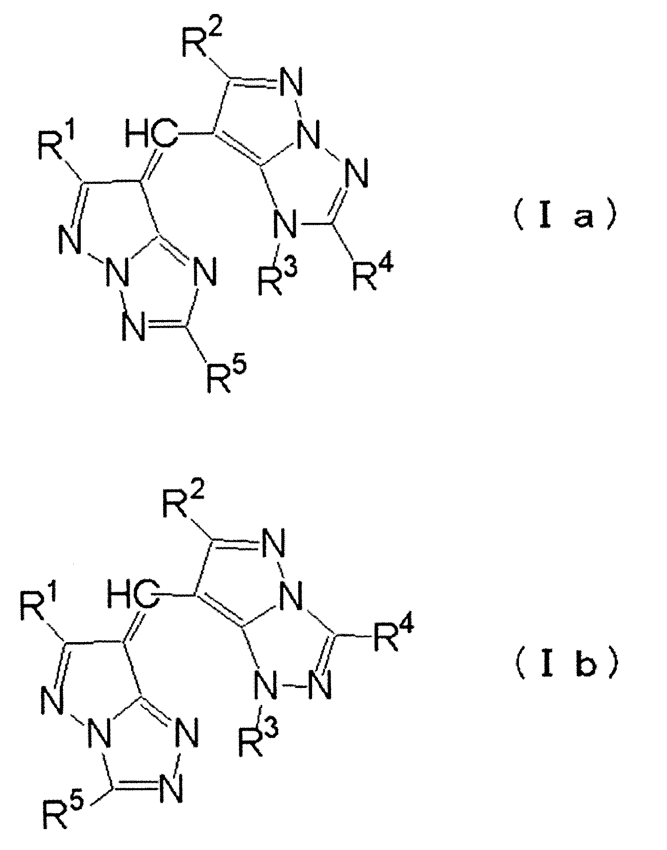
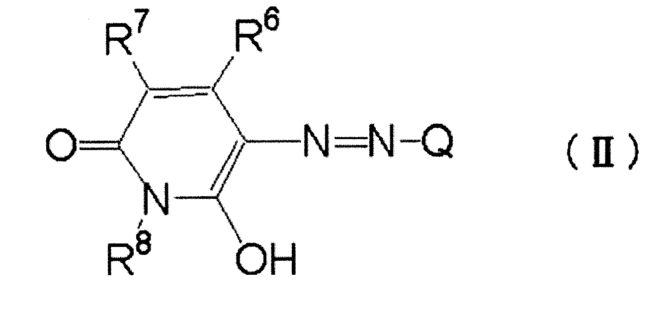
また、グリーン顔料又はシアン顔料と、前記(1)~(3)からなる群より選択される少なくとも1種のイエロー染料と、の可視光領域における分光吸収最大ピーク波長の差が240nm以下であることも好ましい。
また、上記カラーフィルタを備え、色再現性に優れた画像表示装置が提供される。
以下、本発明のカラーフィルタについて詳細に説明する。
本発明のカラーフィルタは、基板上に、グリーン顔料又はシアン顔料と、下記(1)~(3)からなる群より選択される少なくとも1種のイエロー染料と、を含有する緑色の着色領域を有するカラーフィルタである。
(1)構造内にピラゾロトリアゾール環を有するメチン染料
(2)構造内にピリドン環を有するアゾ染料
(3)構造内にピラゾール環を有するアゾ染料
まず、本発明のカラーフィルタにおける緑色の着色領域について詳細に説明する。
本発明のカラーフィルタは、グリーン顔料又はシアン顔料と、特定イエロー染料と、を含有する緑色領域を有する。このような構成の緑色領域は、耐熱性を維持しつつも、高輝度となる。これは、本発明における特定イエロー染料と顔料とを並存させた場合、染料単独で用いた際に形成される会合状態を阻害することなく、むしろそこに顔料の固体粒子を混合することで、更に、強力な会合状態が形成されるため、染料の有する透過光の高透過率を維持しつつ、耐熱性を低下させることがないためと推測される。その結果として、このカラーフィルタは、画像表示装置に適用した際に、色再現性に優れたものとなると考えられる。
以下、本発明における特定イエロー染料とグリーン顔料又はシアン顔料とについて説明する。
(1)構造内にピラゾロトリアゾール環を有するメチン染料
本発明における構造内にピラゾロトリアゾール環を有するメチン染料(以下、「ピラゾロトリアゾールメチン染料」と称する)は、ピラゾロトリアゾール環と、メチン基(メチン鎖)と、が直結した部分構造を含むイエロー染料である。
このピラゾロトリアゾールメチン染料は、分子内に1個又は複数個のピラゾロトリアゾール環を含むが、メチン鎖を挟んで1個ずつ、計2個のピラゾロトリアゾール環を含むことが好ましい。また、奇数個のメチン基からなるメチン鎖を有することも好ましい態様である。メチン基の数は1個であることが、本発明の目的とする色再現の観点から好ましい。

ここで、R1~R5で表される1価の置換基の具体例としては、アルキル基、アリール基、パーフルオロアルキルカルボニル基、アルキルスルホニル基、アルケニルスルホニル基、アリールスルホニル基、ヘテロ環スルホニル基、スルファモイル基、アルキルスルファモイル基、アリールスルファモイル基、又はヘテロ環スルファモイル基等が挙げられる。これらの各基は更に置換基を有していてもよい。

本発明における構造内にピリドン環を有するアゾ染料(以下、「ピリドンアゾ染料」と称する)は、ピリドン環と、アゾ基と、が直結した部分構造を含むイエロー染料である。
なかでも、本発明におけるピリドンアゾ染料としては、色再現及び輝度の点から、下記一般式一般式(II)で表される化合物であることが好ましい。
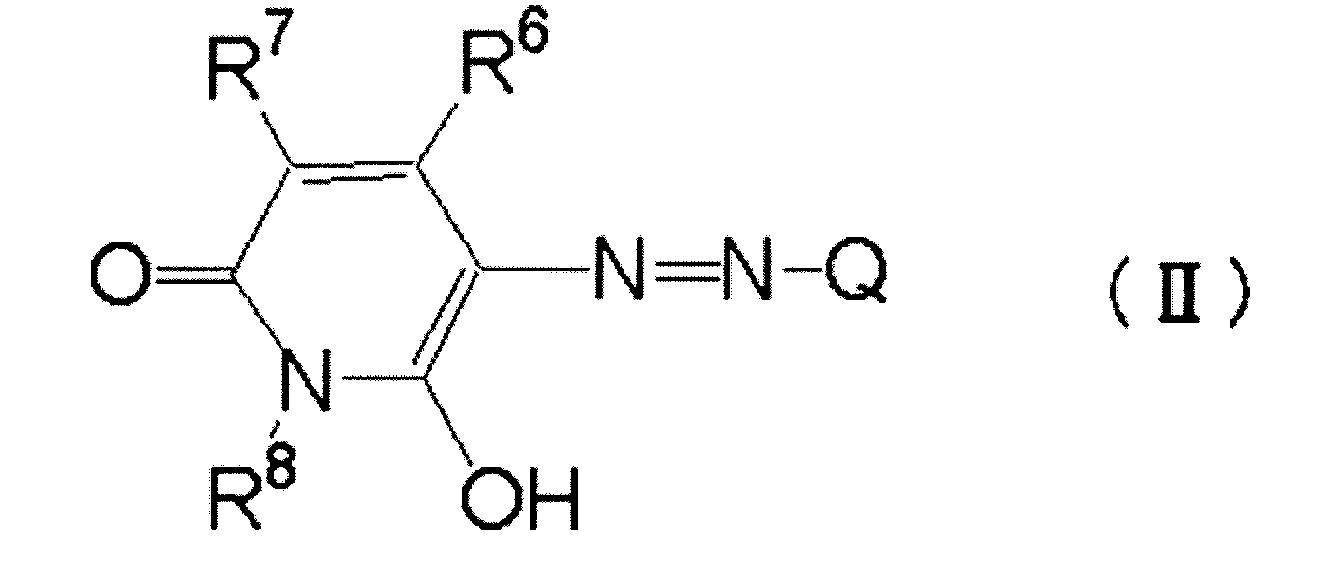
ここで、芳香族ヘテロ環基とは、環内に窒素原子、イオウ原子、酸素原子等のヘテロ原子のいずれかを含む芳香族環であって、5~6員環の芳香族へテロ環基が好ましい。芳香族ヘテロ環基の炭素原子数としては、1~25が好ましく、1~15が更に好ましい。芳香族ヘテロ環としては、具体的には、ピラゾール基、1,2,4-トリアゾール基、イソチアゾール基、ベンゾイソチアゾール基、チアゾール基、ベンゾチアゾール基、オキサゾール基、1,2,4-チアジアゾール基等が挙げられる。

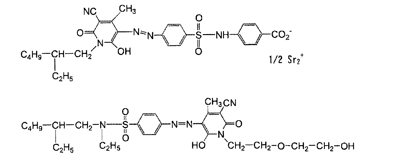
本発明における構造内にピラゾール環を有するアゾ染料(以下、「ピラゾールアゾ染料」と称する)は、ピラゾール環と、アゾ基と、が直結した部分構造を含むイエロー染料である。
このピラゾールアゾ染料は、ピラゾール環と、アゾ基を介して結合するジアゾ成分残基、すなわち、ジアゾ成分「A-NH2」の残基として、アリール基又は芳香族へテロ環基を有することが、色再現、輝度の点から好ましい。
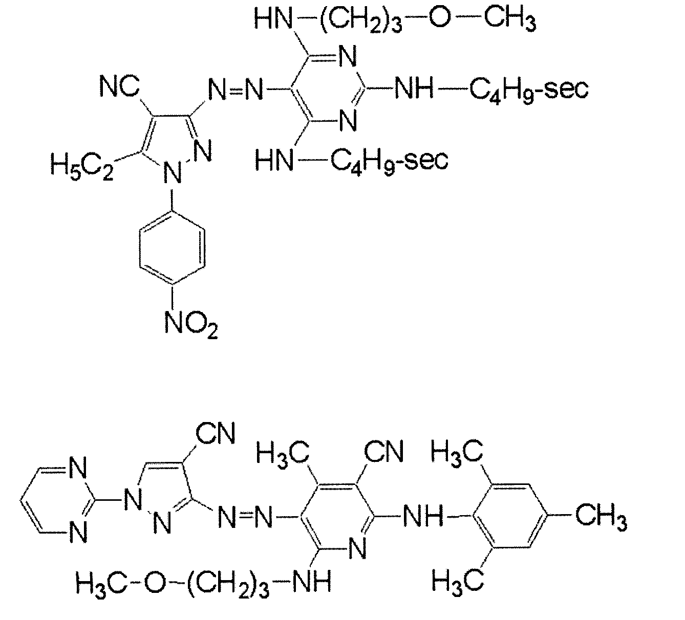
本発明において、緑色領域には、前述した特定イエロー染料と、グリーン顔料又はシアン顔料と、が並存している。
本発明において用いられるグリーン顔料又はシアン顔料としては、公知の顔料(例えば、後述するその他の顔料に列記されたグリーン顔料又はシアン顔料)を用いることができるが、耐熱性の点から、フタロシアニン系顔料が好ましい。
なお、アルミニウムフタロシアニン顔料としては、特開2004-333817号公報に記載のアルミニウムフタロシアニン顔料が好ましく用いられる。
本発明において、グリーン顔料又はシアン顔料と、特定イエロー染料と、の組み合わせとしては、以下の条件を満たすものが好ましい。
即ち、グリーン顔料又はシアン顔料と、特定イエロー染料と、の可視光領域における分光吸収最大ピーク波長の差が130nm以上となる組み合わせが好ましく、140nm以上となる組み合わせがより好ましく、150nm以上となる組み合わせが更に好ましい。上記の差が130nm未満であると、輝度を高めることが困難となる場合がある。
また、グリーン顔料又はシアン顔料と、特定イエロー染料と、の可視光領域における分光吸収最大ピーク波長の差が240nm以下となる組み合わせが好ましく、220nm以下となる組み合わせがより好ましい。上記の差が240nmを超えると、画像表示装置に適用した際に、十分な色再現域を確保することが困難となる場合がある。
本発明においては、特に、グリーン顔料又はシアン顔料と、特定イエロー染料と、の可視光領域における分光吸収最大ピーク波長の差が150nm以上240nm以下となる組み合わせが最も好ましい。
ここで、上記の顔料や染料の分光吸収最大ピーク波長は、以下のようにして測定されたものである。
即ち、後述の実施例に記載のように、上記の顔料や染料を単独で使用した単色のカラーフィルタを作製し、このカラーフィルタについて、大塚電子(株)(Otsuka Electronics Co.,Ltd.)製のMCPD-2000を用いて分光吸収スペクトルを測定する。
なお、本発明における緑色領域中のグリーン顔料又はシアン顔料の含有量は、色再現性、輝度の点から、1質量%~50質量%が好ましく、10質量%~45質量%がより好ましく、15質量%~40質量%が更に好ましい。
本発明における緑色領域は、本発明の効果を損なわない範囲において、前述のグリーン顔料又はシアン顔料、及び特定イエロー染料の他に、その他の染料及び/又は顔料を含有していてもよい。
本発明における緑色領域にその他の染料及び/又は顔料を用いる場合、緑色領域中に含まれる顔料及び染料の総含有量中の、グリーン顔料又はシアン顔料、及び特定イエロー染料の総含有割合を60質量%~100質量%とすることが好ましく、80質量%~100質量%とすることがより好ましい。
本発明に用いられるその他の染料としては、特に制限なく使用することができ、公知の溶剤可溶性染料などから選択することができる。
例えば、特開昭64-90403号公報、特開昭64-91102号公報、特開平1-94301号公報、特開平6-11614号公報、特登2592207号、米国特許第4,808,501号明細書、米国特許第5,667,920号明細書、米国特許第5,059,500号明細書、特開平5-333207号公報、特開平6-35183号公報、特開平6-51115号公報、特開平6-194828号公報等に記載の色素が挙げられる。
化学構造としては、アニリノアゾ系、アリールアゾ、ピラゾロトリアゾールアゾ等のアゾ系、トリフェニルメタン系、アントラキノン系、アンスラピリドン系、ベンジリデン系、オキソノール系、シアニン系、フェノチアジン系、ピロロピラゾールアゾメチン系、キサンテン系、フタロシアニン系、ベンゾピラン系、インジゴ系、等の染料が使用できる。
本発明に用いられるその他の顔料としては、従来公知の種々の無機顔料又は有機顔料を用いることができる。
また、本発明に用いられる顔料は、無機顔料又は有機顔料を問わず、高透過率であることが好ましいことを考慮すると、できるだけ粒子径が小さく微少な粒子サイズの顔料を使用することが好ましい。ハンドリング性をも考慮すると、好ましくは平均粒子径0.01μm~0.3μm、より好ましくは0.01μm~0.15μmの顔料である。該粒径が前記範囲内であると、透過率が高く、色特性が良好であると共に、高いコントラストのカラーフィルタを形成するのに有効である。なお、この好ましい粒子径の値は、前述したグリーン顔料又はシアン顔料にも適用される。
C.I.Pigment Red 1,2,3,4,5,6,7,9,10,14,17,22,23,31,38,41,48:1,48:2,48:3,48:4,49,49:1,49:2,52:1,52:2,53:1,57:1,60:1,63:1,66,67,81:1,81:2,81:3,83,88,90,105,112,119,122,123,144,146,149,150,155,166,168,169,170,171,172,175,176,177,178,179,184,185,187,188,190,200,202,206,207,208,209,210,216,220,224,226,242,246,254,255,264,270,272,279、
C.I.Pigment Green 10,37、
C.I.Pigment Blue 1,2,15,15:1,15:2,15:4,15:6,16,22,60,64,66,79,79のCl置換基をOHに変更したもの,80、
C.I.Pigment Violet 1,19,23,27,32,37,42、
C.I.Pigment Brown 25,28、
C.I.Pigment Black 1,7等を挙げることができる。
有機顔料の微細化には、有機顔料を、水溶性有機溶剤及び水溶性無機塩類と共に高粘度な液状組成物として、摩砕する工程を含む方法を用いることが好ましい。
本発明においては、有機顔料の微細化には、以下の方法を用いることがより好ましい。
即ち、まず、有機顔料、水溶性有機溶剤、及び水溶性無機塩類の混合物(液状組成物)に対し、二本ロール、三本ロール、ボールミル、トロンミル、ディスパー(DISPER)、ニーダー、コニーダー、ホモジナイザー、ブレンダー、単軸若しくは2軸の押出機等の混練機を用いて、強い剪断力を与えることで、混合物中の有機顔料を摩砕した後、この混合物を水中に投入し、攪拌機等でスラリー状とする。次いで、このスラリーをろ過、水洗し、水溶性有機溶剤及び水溶性無機塩を除去した後、乾燥することで、微細化された有機顔料を得る方法である。
また、少量用いることで顔料に吸着して、廃水中に流失しないならば、ベンゼン、トルエン、キシレン、エチルベンゼン、クロロベンゼン、ニトロベンゼン、アニリン、ピリジン、キノリン、テトラヒドロフラン、ジオキサン、酢酸エチル、酢酸イソプロピル、酢酸ブチル、ヘキサン、ヘプタン、オクタン、ノナン、デカン、ウンデカン、ドデカン、シクロヘキサン、メチルシクロヘササン、ハロゲン化炭化水素、アセトン、メチルエチルケトン、メチルイソブチルケトン、シクロヘキサノン、ジメチルホルムアミド、ジメチルスルホキシド、N-メチルピロリドン等を用いてもよい。また、必要に応じて2種類以上の溶剤を混合して使用してもよい。
これら水溶性有機溶剤の使用量は、有機顔料に対して、50質量%~300質量%の範囲が好ましく、より好ましくは100質量%~200質量%の範囲である。
水溶性無機塩の使用量は、有機顔料の1倍質量~50倍質量が好ましく、多い方が摩砕効果はあるが、生産性の点から、より好ましい量は1倍質量~10倍質量である。
また、水溶性無機塩の溶解を防ぐため、摩砕される液状組成物中の水分が1質量%以下であることが好ましい。
上記のような摩砕後の混合物を、80℃の温水と混合することで、水溶性有機溶剤と水溶性無機塩類とを溶解させ、その後、ろ過、水洗し、オーブンで乾燥して、微細な有機顔料を得ることができる。
本発明における緑色領域を形成する際には、グリーン顔料又はシアン顔料(必要に応じて、その他の顔料)を含有する顔料分散組成物が調製され、これを用いることが好ましい。
顔料分散組成物は、顔料を、分散剤や顔料誘導体と共に、溶剤中に分散してなるものである。
ここで用いられる分散剤としては、顔料の分散性を向上させるために用いられるものであり、例えば、公知の顔料分散剤や界面活性剤を適宜選択して用いることができる。
分散剤として、具体的には、多くの種類の化合物を使用可能であり、例えば、オルガノシロキサンポリマーKP341(信越化学工業(株)製)、(メタ)アクリル酸系(共)重合体ポリフロー(POLYFLOW)No.75、No.90、No.95(共栄社化学工業(株)製)、W001(裕商(株)社製)等のカチオン系界面活性剤;ポリオキシエチレンラウリルエーテル、ポリオキシエチレンステアリルエーテル、ポリオキシエチレンオレイルエーテル、ポリオキシエチレンオクチルフェニルエーテル、ポリオキシエチレンノニルフェニルエーテル、ポリエチレングリコールジラウレート、ポリエチレングリコールジステアレート、ソルビタン脂肪酸エステル等のノニオン系界面活性剤;W004、W005、W017(裕商(株)社製)等のアニオン系界面活性剤;EFKA-46、EFKA-47、EFKA-47EA、EFKAポリマー100、EFKAポリマー400、EFKAポリマー401、EFKAポリマー450(いずれもチバ・スペシャルテイケミカル社製)、ディスパースエイド(DISPERSE AID)6、ディスパースエイド8、ディスパースエイド15、ディスパースエイド9100(いずれもサンノプコ社製)等の高分子分散剤;ソルスパース(SOLSPERSE)3000、5000、9000、12000、13240、13940、17000、24000、26000、28000などの各種ソルスパース分散剤(日本ルーブリゾール(株)社製);アデカプルロニック(ADEKA PLURONIC)L31,F38,L42,L44,L61,L64,F68,L72,P95,F77,P84,F87、P94,L101,P103,F108、L121、P-123(旭電化(株)製)及びイソネット(IONET)S-20(三洋化成(株)製)、Disperbyk-101,-103,-106,-108,-109,-111,-112,-116,-130,-140,-142,-161,-162,-163,-164,-166,-167,-170,-171,-174,-176,-180,-182,-2000,-2001,-2050,-2150(ビックケミー・ジャパン(株)社製)が挙げられる。その他、アクリル系共重合体など、分子末端若しくは側鎖に極性基を有するオリゴマー若しくはポリマーが挙げられる。
また、顔料分散組成物には、必要に応じて、顔料誘導体が添加される。
本発明においては、上記分散剤と親和性のある部分、或いは、極性基を導入した顔料誘導体を顔料表面に吸着させ、これを分散剤の吸着点として用いることで、顔料を微細な粒子として顔料分散組成物中に分散させることができ、また、その再凝集をも防止することができる。つまり、顔料誘導体は顔料表面を改質することで、分散剤の吸着を促進させる効果を有する。
顔料分散組成物に使用される溶剤としては、後述する光硬化性組成物に使用される溶剤と同様のものが挙げられる。
顔料分散組成物中の顔料濃度は、30質量%以上90質量%以下が好ましく、40質量%以上80質量%以下がより好ましい。
なお、混合分散工程は、混練分散とそれに続けて行なう微分散処理からなるのが好ましいが、混練分散を省略することも可能である。
分散時間としては、3時間以上6時間以下程度が好適である。
また、ビーズによる微分散処理は、主として、縦型若しくは横型のサンドグラインダー、ピンミル、スリットミル、超音波分散機等、及び、0.01mm以上1mm以下の粒径のガラス、ジルコニア等でできたビーズを用いることができる。
なお、混練、分散についての詳細は、T.C.Patton著”Paint Flow and Pigment Dispersion”(1964年 John Wiley and Sons社刊)等に記載されている。
本発明における緑色領域は、前述の顔料分散組成物を含む光硬化性組成物を用いて形成されることが好ましい。
光硬化性組成物中の顔料の含有量(顔料濃度)は、光硬化性組成物全固形分に対して、30質量%~60質量%であることが好ましく、より好ましくは、35質量%~60質量%であり、更に好ましくは、40質量%~60質量%である。
顔料の濃度が上記範囲であると、色濃度が充分で優れた色特性を確保するのに有効である。
なお、顔料分散組成物に顔料誘導体を用いる場合は、光硬化性組成物の顔料濃度とは、顔料と顔料誘導体との総質量を、光硬化性組成物の総固形分で除した値を用いる。
以下、光硬化性組成物を構成する各成分について説明する。
本発明に用いられる光硬化性組成物は、アルカリ可溶性樹脂を含有することが好ましい。
アルカリ可溶性樹脂としては、線状有機高分子重合体であって、分子(好ましくは、アクリル系共重合体、スチレン系共重合体を主鎖とする分子)中に少なくとも1つのアルカリ可溶性を促進する基(例えば、カルボキシル基、リン酸基、スルホン酸基など)を有するアルカリ可溶性樹脂の中から適宜選択することができる。このうち、更に好ましくは、有機溶剤に可溶で弱アルカリ水溶液により現像可能なものである。
この他、2-ヒドロキシエチルメタクリレートを共重合したもの等も有用なものとして挙げられる。該ポリマーは任意の量で混合して用いることができる。
前記アルキル(メタ)アクリレート及びアリール(メタ)アクリレートの具体例としては、メチル(メタ)アクリレート、エチル(メタ)アクリレート、プロピル(メタ)アクリレート、ブチル(メタ)アクリレート、イソブチル(メタ)アクリレート、ペンチル(メタ)アクリレート、ヘキシル(メタ)アクリレート、オクチル(メタ)アクリレート、フェニル(メタ)アクリレート、ベンジルアクリレート、トリルアクリレート、ナフチルアクリレート、シクロヘキシルアクリレート等を挙げることができる。
本発明に用いられる光硬化性組成物は、分子内にエチレン性不飽和二重結合を有する重合性化合物(以下、単に、「重合性化合物」と称する)を含有することが好ましい。
本発明における重合性化合物としては、エチレン性不飽和二重結合を一つ以上有する重合性モノマー又はオリゴマーが挙げられ、なかでも、エチレン性不飽和二重結合を一つ以上有し、且つ、沸点が常圧で100℃以上である化合物が好ましい。
更に、日本接着協会誌(Journal of the Adhesion Society of Japan)Vol.20、No.7、300~308頁に記載されている光硬化性モノマー及びオリゴマーも使用できる。
重合性化合物の光硬化性組成物中における含有量としては、該組成物の全固形分に対して、2質量%~30質量%が好ましく、より好ましくは3質量%~25質量%であり、特に好ましくは5質量%~20質量%である。重合性化合物が前記範囲内であると、硬化反応が充分に行うことができる。
本発明に用いられる光硬化性組成物は、光重合開始剤を含有することが好ましい。
光重合開始剤としては、例えば、特開平57-6096号公報に記載のハロメチルオキサジアゾール、特公昭59-1281号公報、特開昭53-133428号公報等に記載のハロメチル-s-トリアジン等活性ハロゲン化合物、米国特許第4318791、欧州特許第88050A等の各明細書に記載のケタール、アセタール、又はベンゾインアルキルエーテル類等の芳香族カルボニル化合物、米国特許第4199420号明細書に記載のベンゾフェノン類等の芳香族ケトン化合物、仏国特許第2456741号明細書に記載の(チオ)キサントン類又はアクリジン類の化合物、特開平10-62986号公報に記載のクマリン類又はロフィンダイマー類等の化合物、特開平8-015521号公報等のスルホニウム有機硼素錯体等を挙げることができる。
また、これらの光重合開始剤を、目的に応じて複数種併用することもできる。
本発明に用いられる光硬化性組成物は、一般に上記成分と共に溶剤を用いて好適に調製することができる。
溶剤としては、エステル類、例えば、酢酸エチル、酢酸-n-ブチル、酢酸イソブチル、ギ酸アミル、酢酸イソアミル、酢酸イソブチル、プロピオン酸ブチル、酪酸イソプロピル、酪酸エチル、酪酸ブチル、アルキルエステル類、乳酸メチル、乳酸エチル、オキシ酢酸メチル、オキシ酢酸エチル、オキシ酢酸ブチル、メトキシ酢酸メチル、メトキシ酢酸エチル、メトキシ酢酸ブチル、エトキシ酢酸メチル、エトキシ酢酸エチル、3-オキシプロピオン酸メチル、3-オキシプロピオン酸エチルなどの3-オキシプロピオン酸アルキルエステル類;3-メトキシプロピオン酸メチル、3-メトキシプロピオン酸エチル、3-エトキシプロピオン酸メチル、3-エトキシプロピオン酸エチル、2-オキシプロピオン酸メチル、2-オキシプロピオン酸エチル、2-オキシプロピオン酸プロピル、2-メトキシプロピオン酸メチル、2-メトキシプロピオン酸エチル、2-メトキシプロピオン酸プロピル、2-エトキシプロピオン酸メチル、2-エトキシプロピオン酸エチル、2-オキシ-2-メチルプロピオン酸メチル、2-オキシ-2-メチルプロピオン酸エチル、2-メトキシ-2-メチルプロピオン酸メチル、2-エトキシ-2-メチルプロピオン酸エチル、ピルビン酸メチル、ピルビン酸エチル、ピルビン酸プロピル、アセト酢酸メチル、アセト酢酸エチル、2-オキソブタン酸メチル、2-オキソブタン酸エチル等;エーテル類、例えば、ジエチレングリコールジメチルエーテル、テトラヒドロフラン、エチレングリコールモノメチルエーテル、エチレングリコールモノエチルエーテル、メチルセロソルブアセテート、エチルセロソルブアセテート、ジエチレングリコールモノメチルエーテル、ジエチレングリコールモノエチルエーテル、ジエチレングリコールモノブチルエーテル、プロピレングリコールメチルエーテルアセテート、プロピレングリコールエチルエーテルアセテート、プロピレングリコールプロピルエーテルアセテート等;ケトン類、例えば、メチルエチルケトン、シクロヘキサノン、2-ヘプタノン、3-ヘプタノン等;芳香族炭化水素類、例えば、トルエン、キシレン等が挙げられる。
溶剤は、単独で用いる以外に2種以上を組み合わせて用いてもよい。
本発明に用いられる光硬化性組成物には、必要に応じて、増感色素、水素供与性化合物、フッ素系有機化合物、熱重合開始剤、熱重合成分、熱重合防止剤、その他、充填剤、上述のアルカリ可溶性樹脂(バインダーポリマー)以外の高分子化合物、界面活性剤、密着促進剤、酸化防止剤、紫外線吸収剤、凝集防止剤などの各種添加物を含有することができる。
本発明に用いられる光硬化性組成物は、必要に応じて増感色素を添加してもよい。増感色素は、この増感色素が吸収しうる波長の露光により上記光重合開始剤のラジカル発生反応等や、それによる前記光重合性化合物の重合反応が促進させることができる。
このような増感色素としては、公知の分光増感色素又は染料、又は光を吸収して光重合開始剤と相互作用する染料又は顔料が挙げられる。
本発明に用いられる増感色素として好ましい分光増感色素又は染料は、多核芳香族類(例えば、ピレン、ペリレン、トリフェニレン)、キサンテン類(例えば、フルオレッセイン、エオシン、エリスロシン、ローダミンB、ローズベンガル)、シアニン類(例えば、チアカルボシアニン、オキサカルボシアニン)、メロシアニン類(例えば、メロシアニン、カルボメロシアニン)、チアジン類(例えば、チオニン、メチレンブルー、トルイジンブルー)、アクリジン類(例えば、アクリジンオレンジ、クロロフラビン、アクリフラビン)、フタロシアニン類(例えば、フタロシアニン、メタルフタロシアニン)、ポルフィリン類(例えば、テトラフェニルポルフィリン、中心金属置換ポルフィリン)、クロロフィル類(例えば、クロロフィル、クロロフィリン、中心金属置換クロロフィル)、金属錯体(例えば、下記化合物)、アントラキノン類、(例えば、アントラキノン)、スクアリリウム類(例えば、スクアリリウム)等が挙げられる。

特公平37-13034号公報に記載のスチリル系色素;特開昭62-143044号公報に記載の陽イオン染料;特公昭59-24147号公報記載のキノキサリニウム塩;特開昭64-33104号公報記載の新メチレンブルー化合物;特開昭64-56767号公報記載のアントラキノン類;特開平2-1714号公報記載のベンゾキサンテン染料;特開平2-226148号公報及び特開平2-226149号公報記載のアクリジン類;特公昭40-28499号公報記載のピリリウム塩類;特公昭46-42363号公報記載のシアニン類;特開平2-63053号記載のベンゾフラン色素;特開平2-85858号公報、特開平2-216154号公報の共役ケトン色素;特開昭57-10605号公報記載の色素;特公平2-30321号公報記載のアゾシンナミリデン誘導体;特開平1-287105号公報記載のシアニン系色素;特開昭62-31844号公報、特開昭62-31848号公報、特開昭62-143043号公報記載のキサンテン系色素;特公昭59-28325号公報記載のアミノスチリルケトン;特開平2-179643号公報記載の色素;特開平2-244050号公報記載のメロシアニン色素;特公昭59-28326号公報記載のメロシアニン色素;特開昭59-89303号公報記載のメロシアニン色素;特開平8-129257号公報記載のメロシアニン色素;特開平8-334897号公報記載のベンゾピラン系色素が挙げられる。
増感色素の他の好ましい態様として、以下の化合物群に属しており、且つ、350~450nmに極大吸収波長を有する色素が挙げられる。
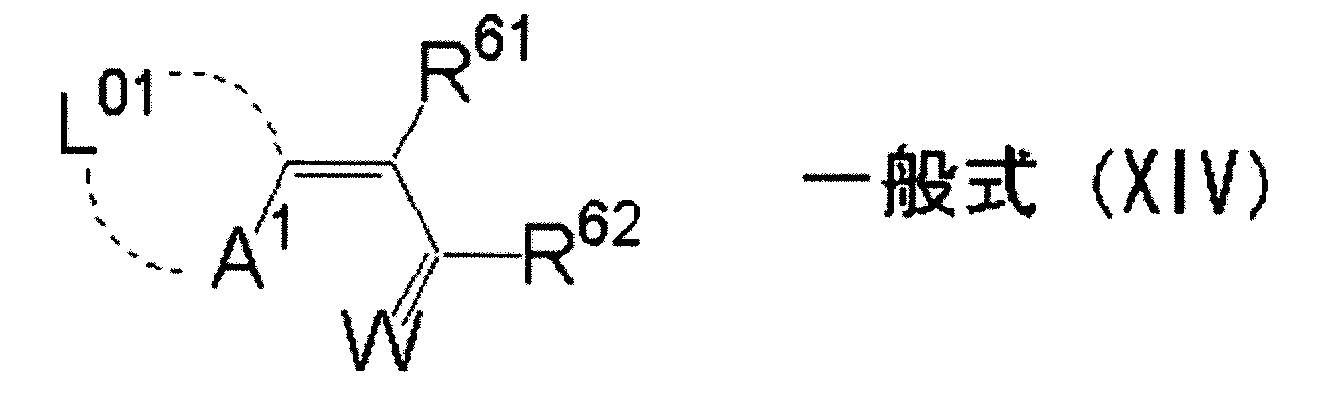
以下に、一般式(XIV)で表される化合物の好ましい具体例〔(F-1)~(F-5)〕を示す。


一般式(XV)で表される化合物の好ましい例としては、以下のもの〔(F-6)~(F-8)〕が挙げられる。
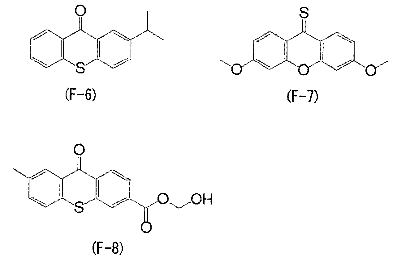

一般式(XVI)で表される化合物の好ましい例としては、以下のもの〔(F-9)~(F-11)〕が挙げられる。
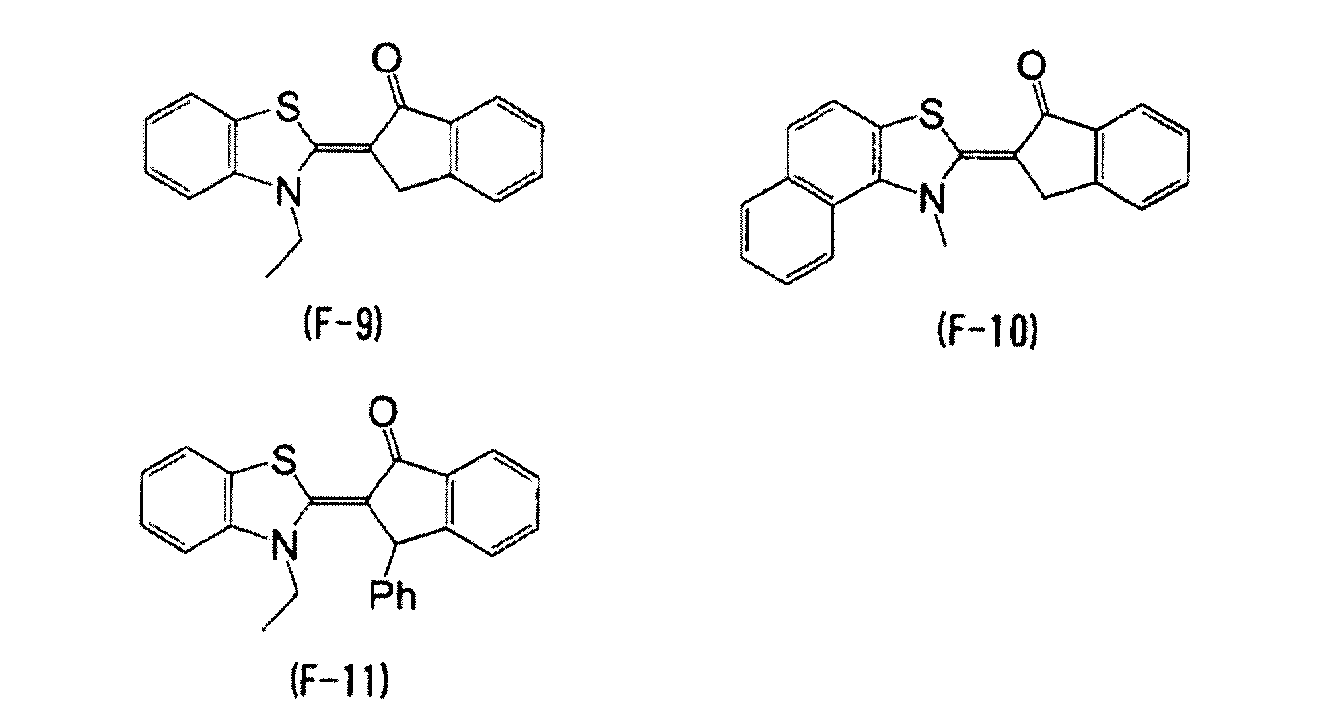

一般式(XVII)で表される化合物の好ましい例としては、以下のもの〔(F-12)~(F-15)〕が挙げられる。
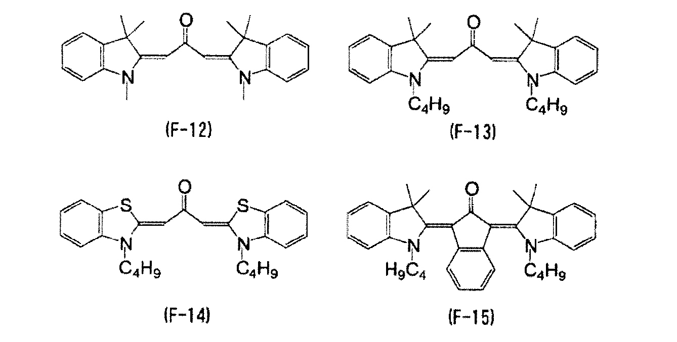

次に、R74、R75、R76の好ましい例について具体的に述べる。好ましいアルキル基の例としては、炭素原子数が1から20までの直鎖状、分岐状、及び環状のアルキル基を挙げることができ、その具体例としては、メチル基、エチル基、プロピル基、ブチル基、ペンチル基、ヘキシル基、ヘプチル基、オクチル基、ノニル基、デシル基、ウンデシル基、ドデシル基、トリデシル基、ヘキサデシル基、オクタデシル基、エイコシル基、イソプロピル基、イソブチル基、s-ブチル基、t-ブチル基、イソペンチル基、ネオペンチル基、1-メチルブチル基、イソヘキシル基、2-エチルヘキシル基、2-メチルヘキシル基、シクロヘキシル基、シクロペンチル基、2-ノルボルニル基を挙げることができる。これらの中では、炭素原子数1から12までの直鎖状、炭素原子数3から12までの分岐状、並びに炭素原子数5から10までの環状のアルキル基がより好ましい。
これらの置換基における、アルキル基の具体例としては、前述のアルキル基が挙げられ、これらは更に置換基を有していてもよい。
なかでも、好ましいA5としては、アルコキシ基、チオアルキル基、アミノ基を有するアリール基が挙げられ、特に好ましいA5としてはアミノ基を有するアリール基が挙げられる。
また、一般式(XVIII)におけるXは、酸素原子、硫黄原子、又は-N(R74)-を表す。

ただし、一般式(XVIII-1)におけるArに導入可能な置換基としては、ハメット値の総和が0以上であることが必須であり、そのような置換基の例としては、トリフルオロメチル基、カルボニル基、エステル基、ハロゲン原子、ニトロ基、シアノ基、スルホキシド基、アミド基、カルボキシル基等を挙げることができる。これら置換基のハメット値を以下に示す。トリフルオロメチル基(-CF3、m:0.43、p:0.54)、カルボニル基(例えば-COHm:0.36、p:0.43)、エステル基(-COOCH3、m:0.37、p:0.45)、ハロゲン原子(例えばCl、m:0.37、p:0.23)、シアノ基(-CN、m:0.56、p:0.66)、スルホキシド基(例えば-SOCH3、m:0.52、p:0.45)、アミド基(例えば-NHCOCH3、m:0.21、p:0.00)、カルボキシル基(-COOH、m:0.37、p:0.45)等が挙げられる。かっこ内は、その置換基のアリール骨格における導入位置と、そのハメット値を表し、(m:0.50)とは、当該置換基がメタ位に導入された時のハメット値が0.50であることを示す。このうち、Arの好ましい例としては置換基を有するフェニル基を挙げることができ、Ar骨格上の好ましい置換基としてはエステル基、シアノ基が挙げられる。置換の位置としてはAr骨格上のオルト位に位置していることが特に好ましい。


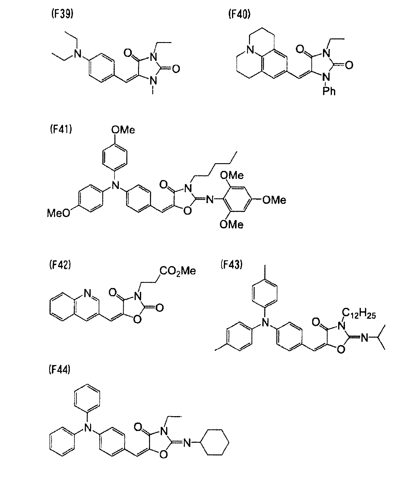

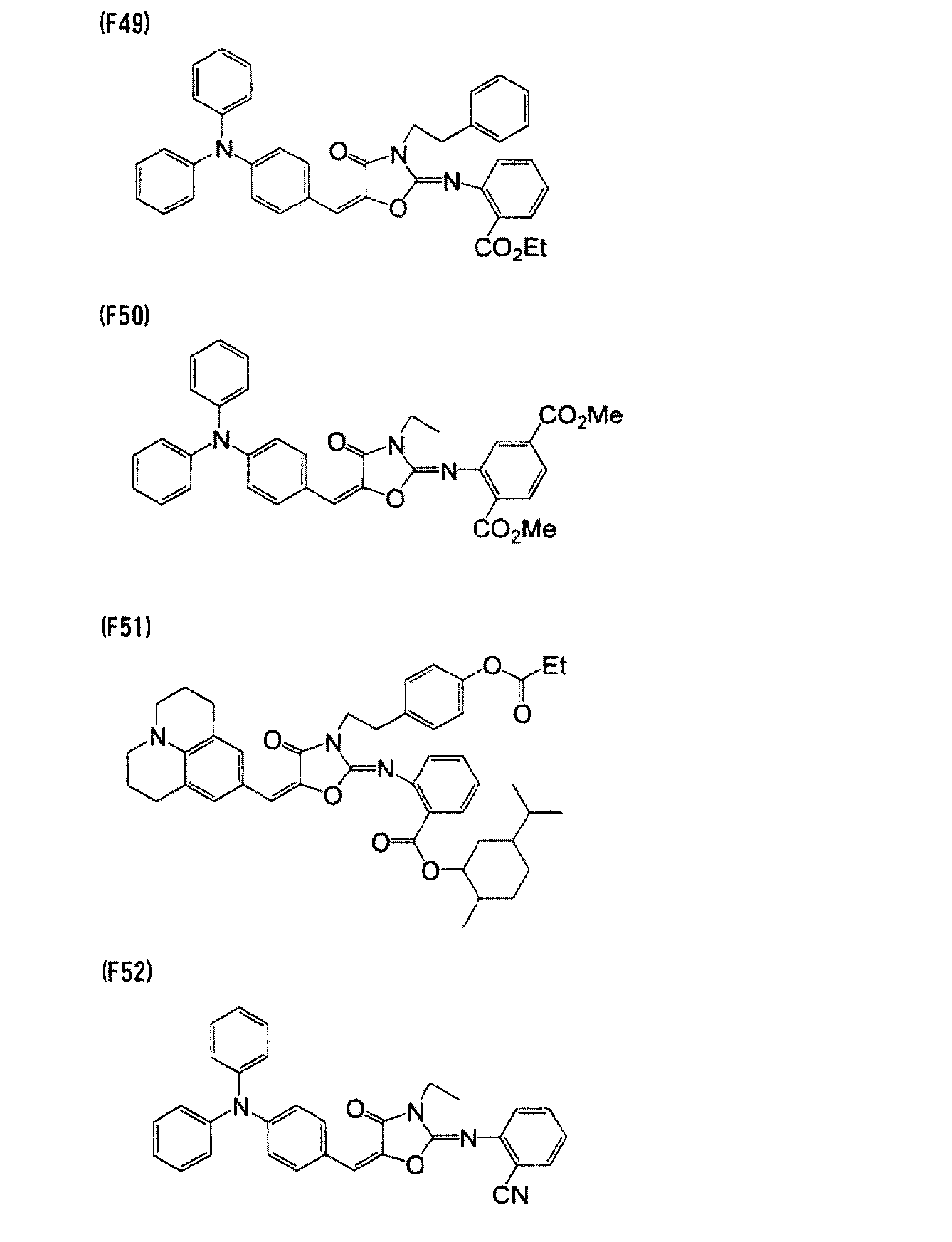

増感色素の含有量がこの範囲であることで、超高圧水銀灯の露光波長に対して高感度であり、膜深部硬化性が得られると共に、現像マージン、パターン形成性の点で好ましい。
本発明に用いられる光硬化性組成物は水素供与性化合物を含有することが好ましい。本発明において水素供与性化合物は、増感色素や光重合開始剤の活性放射線に対する感度を一層向上させる、或いは酸素による重合性化合物の重合阻害を抑制する等の作用を有する。
このような水素供与性化合物の例としては、アミン類、例えば、M.R.Sanderら著「Journal of Polymer Society」第10巻3173頁(1972)、特公昭44-20189号公報、特開昭51-82102号公報、特開昭52-134692号公報、特開昭59-138205号公報、特開昭60-84305号公報、特開昭62-18537号公報、特開昭64-33104号公報、Research Disclosure 33825号記載の化合物等が挙げられ、具体的には、トリエタノールアミン、p-ジメチルアミノ安息香酸エチルエステル、p-ホルミルジメチルアニリン、p-メチルチオジメチルアニリン等が挙げられる。
本発明に用いられる光硬化性組成物は、フッ素系有機化合物を含有することもできる。
このフッ素系有機化合物を含有することで、本発明に用いられる光硬化性組成物を塗布液としたときの液特性(特に流動性)を改善することができ、塗布厚の均一性や省液性を改善することができる。すなわち、被塗布面と塗布液との界面張力が低下することで、被塗布面への濡れ性が改善され、被塗布面への塗布性が向上するので、少量の液量で数μm程度の薄膜を形成した場合であっても、厚みムラの小さい均一厚の膜形成が可能である点で有効である。
本発明に用いられる光硬化性組成物には、熱重合開始剤を含有させることも有効である。熱重合開始剤としては、例えば、各種のアゾ系化合物、過酸化物系化合物が挙げられ、前記アゾ系化合物としては、アゾビス系化合物を挙げることができ、前記過酸化物系化合物としては、ケトンパーオキサイド、パーオキシケタール、ハイドロパーオキサイド、ジアルキルパーオキサイド、ジアシルパーオキサイド、パーオキシエステル、パーオキシジカーボネートなどを挙げることができる。
本発明に用いられる光硬化性組成物には、皮膜の強度を上げるために、熱重合成分を含有させることも有効である。熱重合成分としては、エポキシ化合物が好ましい。
エポキシ化合物は、ビスフェノールA型、クレゾールノボラック型、ビフェニル型、脂環式エポキシ化合物などのエポキシ環を分子中に2個以上有する化合物である。
例えば、ビスフェノールA型としては、エポトート(EPOTOHTO)YD-115、YD-118T、YD-127、YD-128、YD-134、YD-8125、YD-7011R、ZX-1059、YDF-8170、YDF-170など(以上、東都化成製)、デナコール(DENACOL)EX-1101、EX-1102、EX-1103など(以上、ナガセケムテックス(株)製)、プラクセル(PLACCEL)GL-61、GL-62、G101、G102(以上、ダイセル化学製)の他に、これらの類似のビスフェノールF型、ビスフェノールS型も挙げることができる。また、Ebecryl3700、3701、600(以上、ダイセルユーシービー製)などのエポキシアクリレートも使用可能である。
本発明に用いられる光硬化性組成物には、塗布性を改良する観点から、各種の界面活性剤を用いて構成することが好ましく、ノニオン系、カチオン系、アニオン系の各種界面活性剤を使用できる。なかでも、ノニオン系界面活性剤でパーフルオロアルキル基を有するフッ素系界面活性剤が好ましい。
フッ素系界面活性剤の具体例としては、DIC(株)製のメガファック(登録商標)シリーズ、3M社製のフロラード(登録商標)シリーズなどが挙げられる。
上記以外に、添加物の具体例として、ガラス、アルミナ等の充填剤;イタコン酸共重合体、クロトン酸共重合体、マレイン酸共重合体、部分エステル化マレイン酸共重合体、酸性セルロース誘導体、水酸基を有するポリマーに酸無水物を付加させたもの、アルコール可溶性ナイロン、ビスフェノールAとエピクロルヒドリンとから形成されたフェノキシ樹脂などのアルカリ可溶の樹脂;EFKA-46、EFKA-47、EFKA-47EA、EFKAポリマー100、EFKAポリマー400、EFKAポリマー401、EFKAポリマー450(以上、森下産業社製)、ディスパースエイド6、ディスパースエイド8、ディスパースエイド15、ディスパースエイド9100(サンノプコ社製)等の高分子分散剤;ソルスパース3000、5000、9000、12000、13240、13940、17000、24000、26000、28000などの各種ソルスパース分散剤(以上、日本ルーブリゾール(株)社製);アデカプルロニックL31,F38,L42,L44,L61,L64,F68,L72,P95,F77,P84,F87、P94,L101,P103,F108、L121、P-123(以上、旭電化社製)、及びイソネットS-20(以上、三洋化成社製);2-(3-t-ブチル-5-メチル-2-ヒドロキシフェニル)-5-クロロベンゾトリアゾール、アルコキシベンゾフェノン等の紫外線吸収剤;及びポリアクリル酸ナトリウム等の凝集防止剤を挙げることができる。
有機カルボン酸としては、具体的には、例えば、ギ酸、酢酸、プロピオン酸、酪酸、吉草酸、ピバル酸、カプロン酸、ジエチル酢酸、エナント酸、カプリル酸等の脂肪族モノカルボン酸;シュウ酸、マロン酸、コハク酸、グルタル酸、アジピン酸、ピメリン酸、スベリン酸、アゼライン酸、セバシン酸、ブラシル酸、メチルマロン酸、エチルマロン酸、ジメチルマロン酸、メチルコハク酸、テトラメチルコハク酸、シトラコン酸等の脂肪族ジカルボン酸;トリカルバリル酸、アコニット酸、カンホロン酸等の脂肪族トリカルボン酸;安息香酸、トルイル酸、クミン酸、ヘメリト酸、メシチレン酸等の芳香族モノカルボン酸;フタル酸、イソフタル酸、テレフタル酸、トリメリト酸、トリメシン酸、メロファン酸、ピロメリト酸等の芳香族ポリカルボン酸;フェニル酢酸、ヒドロアトロパ酸、ヒドロケイ皮酸、マンデル酸、フェニルコハク酸、アトロパ酸、ケイ皮酸、ケイ皮酸メチル、ケイ皮酸ベンジル、シンナミリデン酢酸、クマル酸、ウンベル酸等のその他のカルボン酸が挙げられる。
本発明に用いられる光硬化性組成物には、以上のほかに、更に、熱重合防止剤を添加することもできる。
熱重合防止剤としては、例えば、ハイドロキノン、p-メトキシフェノール、ジ-t-ブチル-p-クレゾール、ピロガロール、t-ブチルカテコール、ベンゾキノン、4,4’-チオビス(3-メチル-6-t-ブチルフェノール)、2,2’-メチレンビス(4-メチル-6-t-ブチルフェノール)、2-メルカプトベンゾイミダゾール等が有用である。
本発明に用いられる光硬化性組成物は、前述の各成分を必要に応じて選択し、混合することにより、調製することができる。
なお、前述のようにして顔料分散組成物を調製した後、この顔料分散組成物を用いて本発明に用いられる光硬化性組成物を得ることが好ましい。
本発明に用いられる光硬化性組成物の調製に顔料分散組成物を使用する場合、その含有量は、光硬化性組成物の全固形分(質量)に対して、顔料の含有量が30質量%以上60質量%以下の範囲となる量が好ましく、顔料の含有量が35質量%以上60質量%以下の範囲となる量がより好ましく、顔料の含有量が40質量%以上60質量%以下の範囲となる量が更に好ましい。
顔料分散組成物の含有量がこの範囲内であると、色濃度が充分で優れた色特性を確保するのに有効である。
本発明のカラーフィルタは、基板上に緑色領域を有するが、かかる基板上には、この緑色領域以外、赤色(R)領域、青色(B)領域、その他の色の領域を有していてもよい。
このようなカラーフィルタの製造方法には、光硬化性組成物を塗布、プリベーク、露光、及び現像を繰り返すことによって着色パターンを形成する方法が用いられることが好ましい。この方法に、グリーン顔料又はシアン顔料と、特定イエロー染料とを含有する光硬化性組成物(前述の光硬化性組成物)を適用すれば、本発明のカラーフィルタにおける緑色領域が着色パターンとして形成されることになる。また、光硬化性組成物中の顔料及び染料の種類を変化させることで、赤色(R)領域、青色(B)領域、その他の色の領域を、着色パターンとして形成することもできる。
以下、本発明のカラーフィルタについて、その製造方法を通じて詳述する。
このような方法により、各種の画像表示装置に用いられるカラーフィルタをプロセス上の困難性が少なく、高品質で、かつ、低コストに作製することができる。
以下、各工程について詳細に説明する。
まず、塗布工程で用いられる基板について説明する。
本発明のカラーフィルタに用いられる基板としては、例えば、液晶表示素子等に用いられる無アルカリガラス、ソーダガラス、パイレックス(登録商標)ガラス、石英ガラス、及びこれらに透明導電膜を付着させたものや、固体撮像素子等に用いられる光電変換素子基板、例えば、シリコン基板や、プラスチック基板が挙げられる。
これらの基板上には、各画素を隔離するブラックマトリクスが形成されていたり、密着促進等のために透明樹脂層が設けられたりしていてもよい。
また、プラスチック基板は、その表面に、ガスバリヤー層及び/又は耐溶剤性層を有していることが好ましい。
TFT方式液晶駆動用基板における基板としては、例えば、ガラス、シリコン、ポリカーボネート、ポリエステル、芳香族ポリアミド、ポリアミドイミド、ポリイミド等を挙げることができる。これらの基板には、所望により、シランカップリング剤等による薬品処理、プラズマ処理、イオンプレーティング、スパッタリング、気相反応法、真空蒸着等の適宜の前処理を施しておくこともできる。例えば、TFT方式液晶駆動用基板の表面に、窒化ケイ素膜等のパッシベーション膜を形成した基板を用いることができる。
スリットノズル塗布法において、スリット・アンド・スピン塗布法とスピンレス塗布法は、塗布基板の大きさによって条件は異なるが、例えば、スピンレス塗布法により第五世代のガラス基板(1100mm×1250mm)を塗布する場合、スリットノズルからの光硬化性組成物の吐出量は、通常、500マイクロリットル/秒~2000マイクロリットル/秒、好ましくは800マイクロリットル/秒~1500マイクロリットル/秒であり、また、塗工速度は、通常、50mm/秒~300mm/秒、好ましくは100mm/秒~200mm/秒である。
この固形分濃度の調整は、必要であれば、濃縮及び前記した溶剤による希釈によって行われる。
塗布工程で用いられる光硬化性組成物の粘度が上記範囲であることで、塗布された光硬化性組成物による塗布膜の厚みの均一化が図れる。
なお、固体撮像素子用のカラーフィルタの場合であれば、塗膜の厚み(プリベーク処理後)は、0.5μm以上5.0μm以下の範囲が好ましい。
塗布工程後には、塗膜のプリベーク処理が施される。必要によっては、プリベーク前に真空処理を施すこともできる。
真空乾燥の条件は、真空度が、通常、0.1~1.0torr、好ましくは0.2~0.5torr程度である。
また、プリベーク処理は、ホットプレート、オーブン等を用いて50~140℃の温度範囲で、好ましくは70~110℃程度であり、10~300秒の条件にて行なうことができる。なお、プリベーク処理には、高周波処理などを併用してもよい。高周波処理は単独でも使用可能である。
露光工程では、前述のようにして形成された光硬化性組成物からなる塗膜に対し、所定のマスクパターンを介して露光を行う。
露光の際に使用される放射線としては、特に、g線、h線、i線、j線等の紫外線が好ましい。
なお、液晶表示装置用のカラーフィルタを製造する際には、プロキシミテイ露光機、ミラープロジェクション露光機により、主として、h線、i線を使用した露光が好ましく用いられる。
また、固体撮像素子用のカラーフィルタを製造する際には、ステッパー露光機にて、主として、i線を使用することが好ましい。
なお、TFT方式液晶駆動用基板を用いてカラーフィルタを製造する際には、用いられるフォトマスクは、画素(着色パターン)を形成するためのパターンの他、スルーホール或いはU字型の窪みを形成するためのパターンが設けられているものが使用される。
現像工程では、露光後の塗膜の未硬化部を現像液に溶出させ、硬化部のみを基板上に残存させる。
現像温度としては、通常20℃以上30℃以下であり、現像時間としては20秒以上90秒以下である。
現像液としては、未硬化部における光硬化性組成物の塗膜を溶解する一方、硬化部を溶解しないものであれば、いずれのものも用いることができる。
具体的には、種々の有機溶剤の組合せやアルカリ性の水溶液を用いることができる。
また、アルカリ性の水溶液としては、例えば、水酸化ナトリウム、水酸化カリウム、炭酸ナトリウム、炭酸水素ナトリウム、硅酸ナトリウム、メタ硅酸ナトリウム、アンモニア水、エチルアミン、ジエチルアミン、ジメチルエタノールアミン、テトラメチルアンモニウムヒドロキシド、テトラエチルアンモニウムヒドロキシド、コリン、ピロール、ピペリジン、1,8-ジアザビシクロ-[5,4,0]-7-ウンデセン等のアルカリ性化合物を、濃度が0.001~10質量%、好ましくは0.01~1質量%となるように溶解したアルカリ性水溶液が挙げられる。
アルカリ性水溶液には、例えば、メタノール、エタノール等の水溶性有機溶剤や界面活性剤等を適量添加することもできる。
また、固体撮像素子用のカラーフィルタを製造する場合にはパドル現像も用いられる。
リンス工処理は通常は純水で行うが、省液のために、最終洗浄で純水を用い、洗浄初期は使用済の純水を使用したり、また、基板を傾斜させて洗浄したり、超音波照射を併用したりする方法を用いてもよい。
この加熱処理(ポストベーク)は、現像後の塗膜を、上記条件になるようにホットプレートやコンベクションオーブン(熱風循環式乾燥機)、高周波加熱機等の加熱手段を用いて、連続式或いはバッチ式で行なうことができる。
このようなポストベークは、硬化を完全なものとする目的と、現像後のパターン形状を熱変形により順テーパー化させる目的のための工程であり、200℃以上250℃以下の加熱(ハードベーク)を行なうことが一般的である。
基板上のブラックマトリックスは、カーボンブラック、チタンブラックなどの黒色顔料の加工顔料を含有する光硬化性組成物を用い、塗布、露光、及び現像の各工程を経て、その後、必要に応じて、ポストベークすることにより形成することができる。
本発明の画像表示装置は、本発明のカラーフィルタを備える。
カラーフィルタは、少なくともRGBの3色を含み、そのうちG(Green)カラーフィルタが、前記した特定顔料を含む。
カラーフィルタの構成は、これに限定されず、例えば、RGBだけでなく、RGGBでもよいし、RGBWでもよい。ここで、Wは白を示す。
LCD表示装置の構成
CCFL(冷陰極蛍光ランプ:Cold Cathode Fluorescent Lamp)、LED光源等をバックライトとして用いるLCDの場合、偏光板、アレイ基板、液晶層および配向膜、本発明のカラーフィルタ等を積層した液晶パネルを作製し、光源に重ねて配することで本発明の表示装置を得ることができる。また、表示特性を改良するため、導光板や種々光学特性改良フィルムの導入など、公知の手法を用いることも好適である。
なお、これらLCDディスプレイの詳細な構造は、山崎照彦ら著「カラーTFT液晶ディスプレイ 改訂版」(2005年 共立出版社刊)等、多くの公知の情報を参考にすることができる。
白色有機ELを光源として用いる有機ELディスプレイの場合、透明基板上に、本発明のカラーフィルタを積層すると共に、このカラーフィルタ上に、一対の電極基板間に積層された白色発光層を積層することにより、本発明の表示素子であるパネルが得られる。より具体的には、例えば、透明基板上に、カラーフィルタ、TFT回路、有機EL層、及び共通電極を、この順に積層して構成される態様であることが好ましい。
この白色発光層としては、上記一対の電極基板間に電圧が印加されることで、白色光がカラーフィルタに照射される構成であればどのような構成であってもよい。なお、本発明の着色組成物を用いたカラーフィルタは、有機ELディスプレイに使用された場合、該ディスプレイが、白色発光層として青色の光と橙色の光との減色混合により白色光を照射する発光方式を用いた構成である場合に特に有用であり、カラーフィルタの緑色の着色領域における色純度が高く、且つ色ムラの抑制された表示素子が実現される。なお、この場合には、白色発光層としては、青色発光層と橙色発光層とを積層した構成とすればよい。
また、本発明ではTFTの半導体層として酸化物半導体を用いることができる。酸化物半導体は透明なので、電極や絶縁層にも透明材料を用いれば透明なTFTとすることができ、開口率の悪化を防止できる。また、従来のアモルファスSiやポリSiの成膜には200℃以上の高温プロセスが必要なのに対し、酸化物半導体には室温~200℃以下の低温成膜でも良好に動作するものが多く、以降の他の工程(フォトリソグラフィや有機EL層、共通電極の形成)も全て200℃以下で行うことができるため、カラーフィルタを熱により損傷する可能性が少ないという利点がある。更には、カラーフィルタの作製をも200℃以下で行えば、基板としてプラスチックを用いることが可能になり、フレキシブルなELディスプレイとすることもできる。
特にInGaZn酸化物は、室温以上200℃以下のいずれの温度でスパッタ成膜しても移動度5cm2/Vs以上を容易かつ再現性よく得ることができ、好適な材料である。また、InGaZnMg酸化物はInGaZn酸化物と同等の移動度を有し、更にバンドギャップが大きいので紫外線に強い(誤動作しにくい)という特徴を有している。ここで、InGaZn酸化物は、組成比がIn:Ga:Zn:O=1:1:1:4に近いものであるが、実際には若干の酸素空孔が存在し、若干の金属組成ずれがあっても特性は変わらないので、組成比はIn:Ga:Zn:O=(0.7~1.3):(0.7~1.3):(0.7~1.3):(3~4)が許容される。
また、InGaZn酸化物はアモルファス状態を基本とするが、一部微結晶構造を含有してもよい。また、InGaZnMg酸化物は、InGaZn酸化物のZnの一部(50%以下)をMgに置き換えたものである。スパッタとしては、RF或いはDCの反応性スパッタが好適である。
絶縁層としては、酸化シリコンSiOx、窒化シリコンSiNx、酸化アルミニウムAl2O3、酸化タンタルTaOx、酸化イットリウムY2O3、窒素タンタルTaNx等の酸化膜や窒化膜等が好適に用いられる。
これらも、室温以上200℃以下の温度で、スパッタ、レーザアブレーション、蒸着等で成膜できる。特に、反応性スパッタが好適である。製膜後にはポストアニールを行ってもよい。このとき、ポストアニールの温度も、200℃以下であることが好ましい。
本発明では、更に透明な有機絶縁層を用いることも可能である。例えばフッ素樹脂やポリビニルアルコール、エポキシ、アクリル等を使用できる。感光性樹脂を用いると、パターニングが容易となる。更には、異種の絶縁層を重ねてもよい。
正孔輸送層を構成する材料としては、ポリアニリン誘導体、ポリチオフェン誘導体、ポリビニルカルバゾール誘導体、ポリ(3,4-エチレンジオキシチオフェン)とポリスチレンスルホン酸との混合物(PEDOT:PSS)等の導電性高分子材料が挙げられる。
これらの正孔輸送材料は、トルエン、キシレン、アセトン、メチルエチルケトン、メチルイソブチルケトン、シクロヘキサノン、メタノール、エタノール、イソプロピルアルコール、酢酸エチル、酢酸ブチル、水等の単独又は混合溶媒に溶解又は分散させ、スピンコート、バーコート、ワイヤーコート、スリットコート等のコーティング法により塗布できる。また、必要に応じてパターニングを行っても良い。
正孔輸送層には必要に応じて、界面活性剤、酸化防止剤、粘度調整剤、紫外線吸収剤等を添加してもよい。正孔輸送層の膜厚は、10nm~200nmの範囲が好ましい。或いは、TPD(トリフェニルジアミン)、α-NPD(ビス[N-ナフチル-N-フェニル]ベンジディン)などの低分子材料を用いてもよい。
これらの高分子蛍光体はトルエン、キシレン、アセトン、メチルエチルケトン、メチルイソブチルケトン、シクロヘキサノン、メタノール、エタノール、イソプロピルアルコール、酢酸エチル、酢酸ブチル、水等の単独又は混合溶媒に溶解し、スピンコート法、カーテンコート法、バーコート法、ワイヤーコート法、スリットコート法等のコーティング法により塗布できる。また、印刷法により発光層を形成することもできる。
発光層の膜厚は、単層又は多層構造いずれの場合にも合わせて1000nm以下が好ましく、より好ましくは合わせて50nm~150nmの範囲である。
他の材料として、アルミキノリン錯体やジスチリル誘導体等に、キナクリドン、クマリン誘導体、ルブレン、DCM(4-(Dicyanomethylene)-2-methyl-6-(p-dimethylaminostyryl)-4H-pyran)誘導体、ペリレン、イリジウム錯体等をドーピングした低分子蛍光体を用いることができる。
本発明の画像表示装置における有機発光素子は、上記の如き発光特性を有する有機EL発光素子であれば、上記態様に制限されるものではなく、例えば、マクロキャビティ構造を有し、500nm~600nmの範囲に最大発光強度の波長を持つ如き有機EL発光素子と、本発明における特定顔料を含有するカラーフィルタ層を組み合わせて用いた場合でも、本発明の優れた効果を奏するものである。
顔料分散組成物YG-1の調製
下記組成の成分を混合し、ホモジナイザーを用いて回転数3,000r.p.m.で3時間撹拌して混合し、顔料を含む混合溶液を調製した。
組成
・Pigment Yellow 185 125部
・フタロシアニン誘導体 5部
(ソルスパース3000、日本ルーブリゾール(株)製)
・ベンジルメタクリレート/メタクリル酸(=70/30[モル比])共重合体(Mw:5,000)のプロピレングリコールモノメチルエーテルアセテート溶液
(固形分50%) 15部
・分散剤(Disperbyk-161、ビックケミー・ジャパン(株)製) 60部
・プロピレングリコールモノメチルエーテルアセテート 795部
顔料分散組成物YG-1の調製に用いた「Pigment Yellow 185」を、「Pigment Yellow 150」(YG-2)、「Pigment Green 7」(CG-1)、「Pigment Green 36」(CG-2)、「特開2004-333817号公報の段落〔0021〕に記載の構造式(II)で表されるアルミニウムフタロシアニン顔料」(CG-3)、及び、「Pigment Green 58」(CG-4)に、それぞれ変更した以外は同様にして、顔料分散組成物YG-2、CG-1、CG-2、CG-3、CG-4を調製した。
なお、得られた光硬化性組成物CMYG-1中の固形分濃度は、24.1質量%であった。また、得られた光硬化性組成物CMYG-1の全固形分中の顔料濃度は30.0%であった。
・顔料分散組成物YG-1 100部
・ベンジルメタクリレート/メタクリル酸(=70/30[モル比])共重合体(Mw:30,000)のプロピレングリコールモノメチルエーテルアセテート溶液(固形分50%) 12部
・DPHA(日本化薬社製)ジペンタエリスリトールペンタアクリレート 12部
・2-(o-クロロフェニル)-4,5-ジフェニルイミダゾリル二量体(光重合開始剤) 3部
・4,4’-ビス(ジエチルアミノ)ベンゾフェノン(増感色素) 4.5部
・2-メルカプトベンゾチアゾール(水素供与性化合物) 2部
・重合禁止剤:p-メトキシフェノール 0.001部
・フッソ系界面活性剤(商品名:Megafac R08 DIC(株)製) 0.5部
・プロピレングリコールモノメチルエーテルアセテート 61部
前記にて得られた光硬化性組成物CMYG-1(カラーレジスト液)を、550mm×650mmのガラス基板に下記条件でスリット塗布した後、10分間そのままの状態で待機させ、真空乾燥とプリベーク(90℃のオーブンで60秒間乾燥)を施した。
これにより、着色剤として、顔料であるPigment Yellow 185のみを含む着色領域を有するカラーフィルタ(PY185)を得た。
塗布ヘッド先端の開口部の間隙:50μm
塗布速度:100mm/秒
基板と塗布ヘッドとのクリヤランス:150μm
塗布厚(乾燥厚):2.2μm
塗布温度:23℃
光硬化性組成物CMYG-1の調製において用いた「顔料分散組成物YG-1」を、「顔料分散組成物YG-2」、「顔料分散組成物CG-1」、「顔料分散組成物CG-2」、「顔料分散組成物CG-3」、及び、「顔料分散組成物CG-4」に、それぞれ代えた以外は同様にして、光硬化性組成物CMYG-2、CMCG-1、CMCG-2、CMCG-3、及び、CMCG-4を調製した。
その後、これらを用いて、カラーフィルタ(PY185)の作製方法と同様の方法を用い、カラーフィルタ(PY150)、カラーフィルタ(PG7)、カラーフィルタ(PG36)、カラーフィルタ(アルミニウムフタロシアニン)、及び、カラーフィルタ(PG58)を作製した。
光硬化性組成物CMYG-1の調製において用いた「顔料分散組成物YG-1」を、「12.5質量%で含む染料Y-1のシクロヘキサノン溶液」、「12.5質量%で含む染料Y-5のシクロヘキサノン溶液」、「12.5質量%で含む染料Y-6のシクロヘキサノン溶液」、「12.5質量%で含む染料Y-7のシクロヘキサノン溶液」、「12.5質量%で含む染料Y-8のシクロヘキサノン溶液」、「12.5質量%で含む染料Y-9のシクロヘキサノン溶液」、及び、「12.5質量%で含む染料C-1のシクロヘキサノン溶液」に、それぞれ代えた以外は同様にして、光硬化性組成物CMY1、CMY5、CMY6、CMY7、CMY8、CMY9、及び、CMC1を調製した。
また、得られた光硬化性組成物を用いて、カラーフィルタ(PY185)の作製方法と同様の方法を用い、カラーフィルタ(Y-1)、カラーフィルタ(Y-5)、カラーフィルタ(Y-6)、カラーフィルタ(Y-7)、カラーフィルタ(Y-8)、カラーフィルタ(Y-9)、及び、カラーフィルタ(C-1)を作製した。
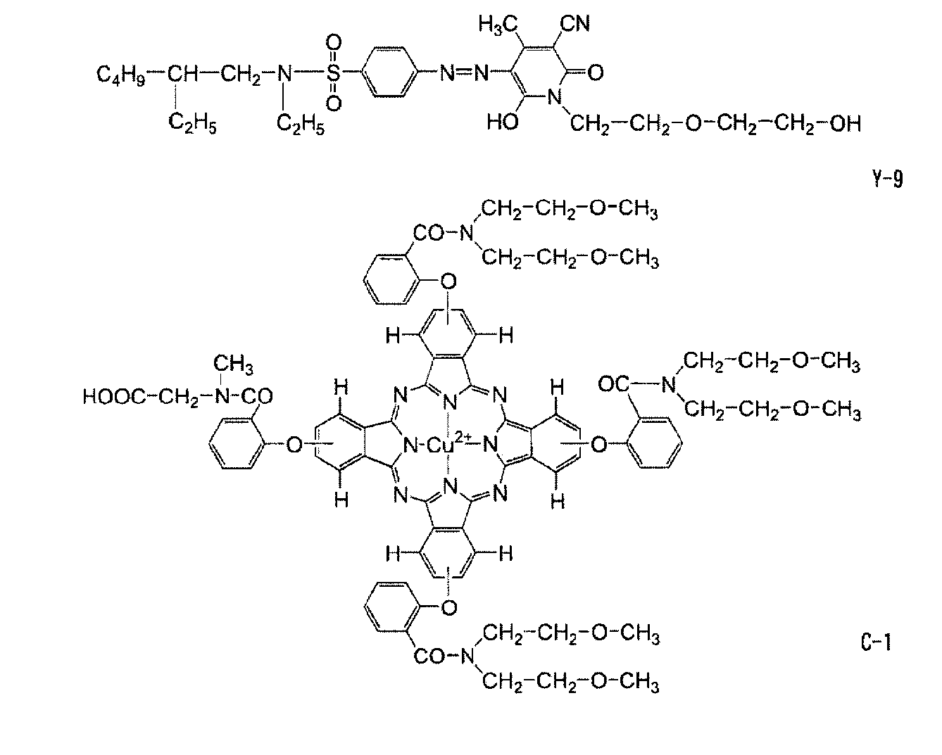
前述のようにして得られた、顔料単色カラーフィルタ、染料単色カラーフィルタの各々について、大塚電子(株)製のMCPD-2000を用いて分光吸収スペクトルを測定した。
代表的なものを図1(イエロー色素)及び図2(シアン(グリーン)色素)に示す。
図1及び図2に示された結果から、染料のみを用いて作製した単色カラーフィルタは、いずれも緑光領域における最低濃度付近(イエロー色素における波長510nm~600nm、シアン(グリーン)色素における波長450nm~515nm)の光学濃度が低いことが分かる。
なお、図1及び図2に示していないカラーフィルタについても同様の傾向が得られた。
単色カラーフィルタの作製
前述の実験例の結果をもとに、実験例において、光硬化性組成物を作製する際に用いた顔料分散組成物及び/又は染料溶液を用いて、緑色領域Gについて、C光源を用いてCIE標準のNTSC規格値を満たすように、顔料分散組成物、及び染料溶液の使用量、更には、その使用比率を調節し、光硬化性組成物を調製した。
得られた光硬化性組成物を用いて、実験例におけるカラーフィルタ(PY185)の作製方法と同様の方法を用い、カラーフィルタCF-A1~CF-A3(比較例A1~A3)及びCF-A4~CF-A14(実施例A1~A11)を作製した。
作製したカラーフィルタCF-A1~CF-A14に使用した顔料及び染料の種類と顔料及び染料の使用量を下記表1に示す。また、カラーフィルタCF-A1~CF-A14に使用した顔料及び染料の分光吸収最大ピーク波長の差についても、表1に併記した。
作製したカラーフィルタCF-A1~CF-A14に対し、C光源を透過させる簡易な表示装置を作製した。表示装置に対して法線方向に色彩輝度計((株)トプコン社製 BM-5A)を設置して、各カラーフィルタを用いた場合の色度(x値、y値)、及び輝度(cd/m2)を測定し、結果を、カラーフィルタCF-A2の結果を基準とした相対値で表2に示す。
また、耐熱性の評価として、カラーフィルタCF-A1~CF-A14を220℃のオーブンで1時間加熱処理し(ポストベーク)、加熱前後のスペクトルを大塚電子(株)製のMCPD-2000を用いて測定し、最大濃度値の変化を耐熱性の指標とした。
これらの結果を表1に併記した。
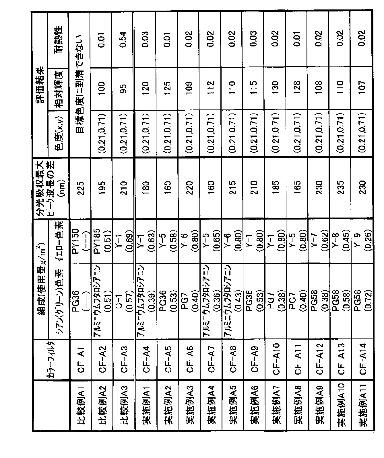
即ち、比較例A1のカラーフィルタCF-A1は、従来からの液晶用のグリーンのカラーフィルタに用いられる汎用顔料を含有する光硬化性組成物用いて作製しようとしたものであるが、C光源のようなブロードな光源を用いて、NTSC規格値の色度に到達することはできなかった。
一方、比較例A2のカラーフィルタCF-A2のように顔料種を選択することで、目標色度に到達することは可能であるが、輝度の点からは、実施例A1~A11のカラーフィルタCF-A4~CF-A14に劣ることが分かる。
更に、染料のみで作製した比較例A3のカラーフィルタCF-A3では、図1及び図2に示されるように、使用した染料単独のG領域の光学濃度は低いにもかかわらず、NTSC規格値の色度を達成しようとすると、顔料のみで作製されるカラーフィルタCF-A2に対し、高い透過率が得られないことが分かる。また、これに対応して、カラーフィルタCF-A3の輝度は、カラーフィルタCF-A2よりも劣ることが分かる。更に、このカラーフィルタCF-A3では、色材として染料のみを使用していることから、加熱前後において、光学濃度の大きな低下が観察され、耐熱性が低いことが分かる。
更に、カラーフィルタCF-A4~CF-A14は、顔料を単独で含むカラーフィルタCF-A2と同程度、又はカラーフィルタCF-A2に対して遜色のないレベルの耐熱性を有していることが分かる。この効果は、緑色領域中の染料の使用量を少なくしたといった理由のみでは説明のできない効果であり、ここに色再現、輝度を両立し耐熱性に問題のないカラーフィルタを提供することが可能となった。
液晶表示装置の作製
以下の手法によりカラーフィルタCF-B1~CF-B3(比較例B1~比較例B3)及びCF-B4~CF-B14(実施例B1~実施例B11)を作製し、これを用いて液晶表示装置LCD-B1~LCD-B14を作製し表示特性の評価を行った。
下記組成の顔料分散組成物を調整し、顔料分散組成物YG-1作製時と同様に分散処理を行って赤色顔料分散物R1を作製した。
〔赤色顔料分散物R1組成〕
・Pigment Red 254 75部
・Pigment Red 177 50部
・ベンジルメタクリレート/メタクリル酸共重合体 70部
(共重合組成比70/30 重量平均分子量30000、酸価40)
・プロピレングリコールモノメチルエーテルアセテート 800部
〔赤色着色感光性樹脂組成物R組成〕
・赤色顔料分散物R1 100部
・ベンジルメタクリレート/メタクリル酸(=70/30[モル比])共重合体(Mw:30,000)のプロピレングリコールモノメチルエーテルアセテート溶液
(固形分50%) 12部
・DPHA(日本化薬社製) 12.1部
・2-(o-クロロフェニル)-4,5-ジフェニルイミダゾリル二量体
(光重合開始剤) 3.1部
・4,4’-ビス(ジエチルアミノ)ベンゾフェノン(増感色素) 4.2部
・2-メルカプトベンゾチアゾール(水素供与性化合物) 2.1部
・重合禁止剤:p-メトキシフェノール 0.001部
・フッソ系界面活性剤(商品名:MEGAFAC R08 DIC(株)製) 0.5部
・プロピレングリコールモノメチルエーテルアセテート 60部
赤色着色感光性樹脂組成物Rの作製において、Pigment Red 254に代えてPigment Blue 15:6を113部、Pigment Red 177に代えてPigment Violet 23を12部使用した他は同様にして、青色着色感光性樹脂組成物Bを作製した。
下記組成の顔料分散組成物を調整し、赤色顔料分散物R1作製時と同様に分散処理を行って黒色顔料分散物K1を作製した。
黒色顔料分散物K1組成
・カーボンブラック(商品名:Nipex35、デグサジャパン(株)製) 13.1部
・ポリマー(ベンジルメタクリレート/メタクリル酸=72/28モル比のランダム共重合物、分子量3.7万) 6.7部
・プロピレングリコールモノメチルエーテルアセテート 79.1部
・分散剤(下記化合物) 0.65部
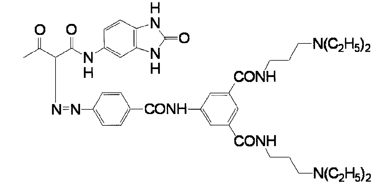
〔黒色着色感光性樹脂組成物K組成〕
・黒色顔料分散物K1 25部
・プロピレングリコールモノメチルエーテルアセテート 8.5部
・メチルエチルケトン 53部
・バインダー(ポリマー(ベンジルメタクリレート/メタクリル酸=78/22モル比のランダム共重合物、分子量3.8万)27部とプロピレングリコールモノメチルエーテルアセテート73部の混合物) 9.1部
・ヒドロキノンモノメチルエーテル 0.002部
・DPHA(日本化薬社製) 12部・2,4―ビス(トリクロロエチル)―6―[4‘―(N,Nビスエトキシカルボニルメチル)アミノ―3’―ブロモフェニル]―s―トリアジン 0.16部
・界面活性剤(下記化合物)のメチルエチルケトン30重量%溶液 0.042部
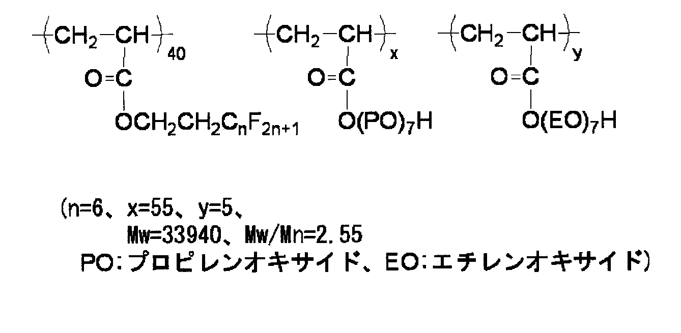
ブラックマトリクスの形成
無アルカリガラス基板を、UV洗浄装置で洗浄後、洗浄剤を用いてブラシ洗浄し、更に超純水で超音波洗浄した。該基板を120℃3分熱処理して表面状態を安定化させた後、該基板を冷却し23℃に温調した。
該基板にスリット状ノズルを有するガラス基板用コーター(エフ・エー・エス・アジア社製、商品名:MH-1600)にて、前記の黒色着色感光性樹脂組成物Kを塗布した。引き続きVCD(真空乾燥装置;東京応化工業(株)社製)で30秒間、溶媒の一部を乾燥して塗布層の流動性を無くした後、120℃で3分間プリベークして膜厚2.4μmの黒色感光性樹脂層を得た。
超高圧水銀灯を有すプロキシミティ型露光機(日立ハイテク電子エンジニアリング(株)社製)で、基板とマスク(画像パターンを有す石英露光マスク)を垂直に立てた状態で、露光マスク面と該感光性樹脂層の間の距離を200μmに設定し、露光量300mJ/cm2でパターン露光した。
前記ブラックマトリクスを形成したガラス基板に、赤色着色感光性樹脂組成物R、緑色着色感光性樹脂組成物(前記実施例Aの、CF-A1~CF-A14作製に使用したもの)、青色着色感光性樹脂組成物Bを、それぞれ順にブラックマトリクス形成時と同様の工程にて積層およびパターニングし、RGB3色画素のカラーフィルタを得た。このとき、RGB各色の着色部膜厚は1.6μmであった。各フィルタの名称は、使用した緑色着色感光性樹脂組成物に応じてCF-B1~CF-B14とした。
カラーフィルタが形成されたガラス基板をスパッタ装置に入れて、100℃で1300Å厚さのITOを全面真空蒸着した後、240℃で90分間アニールしてITOを結晶化し、ITO透明電極を形成した。
特開2004-240335号公報の[実施例1]に記載のスペーサ形成方法と同様の方法で、上記で作製したITO透明電極上にスペーサを形成した。
下記のポジ型感光性樹脂層用塗布液を用いて、前記スペーサを形成したITO透明電極上に液晶配向制御用突起を形成した。
但し、露光、現像、及び、ベーク工程は、以下の方法を用いた。
所定のフォトマスクが感光性樹脂層の表面から100μmの距離となるようにプロキシミティ露光機(日立ハイテク電子エンジニアリング株式会社製)を配置し、該フォトマスクを介して超高圧水銀灯により照射エネルギー150mJ/cm2でプロキシミティ露光した。
続いて、2.38%テトラメチルアンモニウムヒドロキシド水溶液を、シャワー式現像装置にて33℃で30秒間基板に噴霧しながら現像した。こうして、感光性樹脂層の不要部(露光部)を現像除去することにより、カラーフィルタ側基板上に、所望の形状にパターニングされた感光性樹脂層よりなる液晶配向制御用突起が形成された液晶表示装置用基板を得た。
次いで、該液晶配向制御用突起が形成された液晶表示装置用基板を230℃下で30分ベークすることにより、液晶表示装置用基板上に硬化された液晶配向制御用突起を形成した。
・ポジ型レジスト液(富士フイルムエレクトロニクスマテリアルズ(株)社製
FH-2413F) 53.0部
・メチルエチルケトン 46.5部
・メガファックF-780F(DIC(株)社製) 0.05部
上記で得られた液晶表示装置用基板上に、さらにポリイミドよりなる配向膜を設けた。その後、カラーフィルタの画素群を取り囲むように周囲に設けられたブラックマトリックス外枠に相当する位置にエポキシ樹脂のシール剤を印刷し、MVAモード用液晶を滴下し、対向基板と貼り合わせた後、貼り合わされた基板を熱処理してシール剤を硬化させた。
このようにして得た液晶セルの両面に、(株)サンリッツ社製の偏光板HLC2-2518を貼り付けた。次いで、光源としてLED光源(SONY社製液晶テレビ、KDL-40ZX1のバックライト光源)を前記偏光板が設けられた液晶セルの背面となる側に配置し、液晶表示装置(LCD)を得た。表示装置名は、使用したカラーフィルタCF-B1~CF-B14に応じ、LCD-B1~LCD-B14とした。
LCD-B1~LCD-B14の画像特性評価を、官能法によって評価した。具体的には、10人の被験者を選定し、カラーストライプ画像など数種の静止画像をLCD-B1~LCD-B14に表示して画質を評価させた。その際、検査者側、被験者側ともに現在評価している表示装置の種類が分からないように配慮して評価を行った。
評価は、被験者に画質が良いと思う表示装置から順に14~1のスコアを付けてもらい、10人の被験者の合計点から求めた。下記表2に結果を示す。
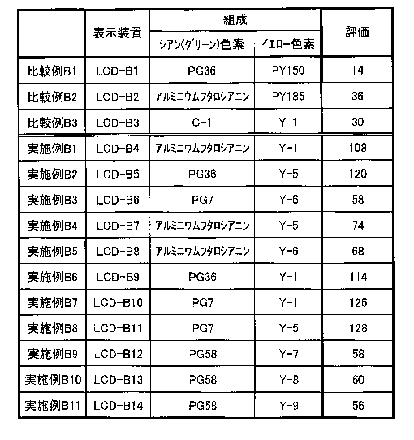
本実施例ではMVAモード液晶表示装置にて画質評価を行ったが、他のモードの液晶表示装置、ないしはカラーフィルタ方式の有機ELディスプレイにおいても、本発明による高い輝度を有するカラーフィルタは画質向上に寄与できると考えられる。
Claims (9)
- 基板;及び
該基板上に、グリーン顔料又はシアン顔料と、下記(1)~(3)からなる群より選択される少なくとも1種のイエロー染料と、を含有する緑色の着色領域
を有するカラーフィルタ:
(1)構造内にピラゾロトリアゾール環を有するメチン染料;
(2)構造内にピリドン環を有するアゾ染料;
(3)構造内にピラゾール環を有するアゾ染料。 - 前記(1)構造内にピラゾロトリアゾール環を有するメチン染料が、下記一般式(Ia)又は(Ib)で表される化合物である請求項1に記載のカラーフィルタ:
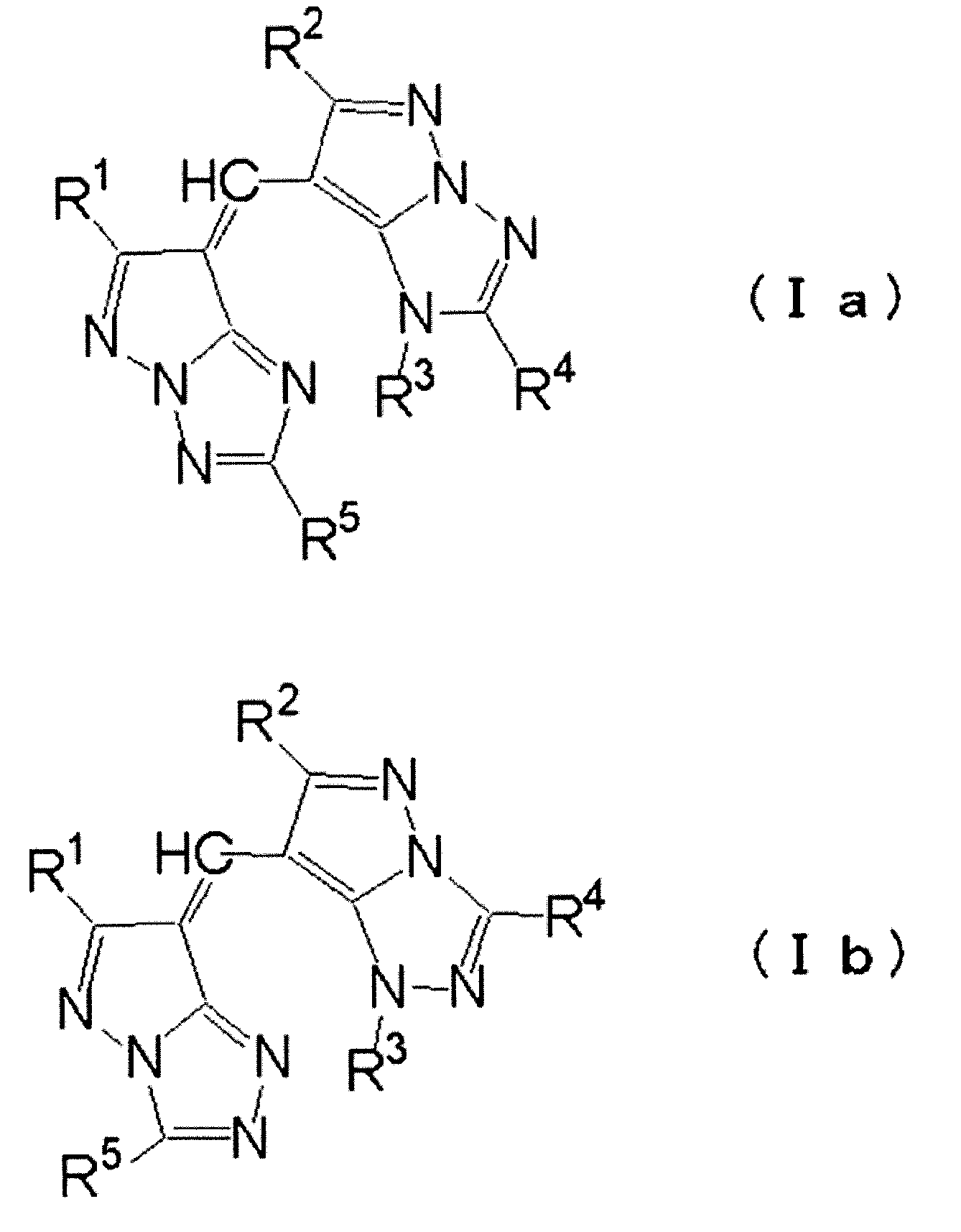
- 前記一般式(Ia)又は(Ib)においてR1~R5で表される1価の置換基が、アルキル基、アリール基、パーフルオロアルキルカルボニル基、アルキルスルホニル基、アルケニルスルホニル基、アリールスルホニル基、ヘテロ環スルホニル基、スルファモイル基、アルキルスルファモイル基、アリールスルファモイル基、又はヘテロ環スルファモイル基であり、これらの各基は更に置換基を有していてもよい請求項2に記載のカラーフィルタ。
- 前記一般式(Ia)又は(Ib)において、R1及びR2の各々が直鎖アルキル基又は分岐アルキル基であり;R4及びR5の各々がアルキル基又はアリール基であり;R3が水素原子、アルキル基又はアリール基である請求項2又は3に記載のカラーフィルタ。
- 前記(2)構造内にピリドン環を有するアゾ染料が、下記一般式(II)で表される化合物である請求項1~4のいずれか1項に記載のカラーフィルタ:

- 前記一般式(II)においてR6又はR7で表される1価の置換基が、ハロゲン原子、脂肪族基、アリール基、ヘテロ環基、シアノ基、カルボキシル基、カルバモイル基、脂肪族オキシカルボニル基、アリールオキシカルボニル基、アシル基、ヒドロキシ基、脂肪族オキシ基、アリールオキシ基、アシルオキシ基、カルバモイルオキシ基、ヘテロ環オキシ基、アミノ基、脂肪族アミノ基、アリールアミノ基、ヘテロ環アミノ基、アシルアミノ基、カルバモイルアミノ基、スルファモイルアミノ基、脂肪族オキシカルボニルアミノ基、アリールオキシカルボニルアミノ基、脂肪族スルホニルアミノ基、アリールスルホニルアミノ基、ニトロ基、脂肪族チオ基、アリールチオ基、脂肪族スルホニル基、アリールスルホニル基、スルファモイル基、スルホ基、イミド基、又はヘテロ環チオ基である請求項1~5のいずれか1項に記載のカラーフィルタ。
- 前記グリーン顔料又はシアン顔料と、前記(1)~(3)からなる群より選択される少なくとも1種のイエロー染料と、の可視光領域における分光吸収最大ピーク波長の差が130nm以上である請求項1~請求項6のいずれか1項に記載のカラーフィルタ。
- 前記グリーン顔料又はシアン顔料と、前記(1)~(3)からなる群より選択される少なくとも1種のイエロー染料と、の可視光領域における分光吸収最大ピーク波長の差が240nm以下である請求項1~請求項7のいずれか1項に記載のカラーフィルタ。
- 請求項1~請求項8のいずれか1項に記載のカラーフィルタを備えた画像表示装置。
Priority Applications (3)
| Application Number | Priority Date | Filing Date | Title |
|---|---|---|---|
| KR1020127005075A KR101574991B1 (ko) | 2009-09-04 | 2010-08-04 | 컬러필터 및 그것을 구비한 화상표시장치 |
| US13/393,478 US20120205599A1 (en) | 2009-09-04 | 2010-08-04 | Color filter and image display apparatus having the same |
| CN2010800383969A CN102483479A (zh) | 2009-09-04 | 2010-08-04 | 滤色器及具备其的图像显示装置 |
Applications Claiming Priority (6)
| Application Number | Priority Date | Filing Date | Title |
|---|---|---|---|
| JP2009-205203 | 2009-09-04 | ||
| JP2009205203 | 2009-09-04 | ||
| JP2010-007207 | 2010-01-15 | ||
| JP2010007207 | 2010-01-15 | ||
| JP2010118471A JP5705459B2 (ja) | 2009-09-04 | 2010-05-24 | カラーフィルタ用光硬化性組成物、該光硬化性組成物により形成されたカラーフィルタ、及びそれを備えた画像表示装置 |
| JP2010-118471 | 2010-05-24 |
Publications (1)
| Publication Number | Publication Date |
|---|---|
| WO2011027643A1 true WO2011027643A1 (ja) | 2011-03-10 |
Family
ID=43649190
Family Applications (1)
| Application Number | Title | Priority Date | Filing Date |
|---|---|---|---|
| PCT/JP2010/063196 Ceased WO2011027643A1 (ja) | 2009-09-04 | 2010-08-04 | カラーフィルタ、及びそれを備えた画像表示装置 |
Country Status (6)
| Country | Link |
|---|---|
| US (1) | US20120205599A1 (ja) |
| JP (1) | JP5705459B2 (ja) |
| KR (1) | KR101574991B1 (ja) |
| CN (1) | CN102483479A (ja) |
| TW (1) | TWI518380B (ja) |
| WO (1) | WO2011027643A1 (ja) |
Cited By (10)
| Publication number | Priority date | Publication date | Assignee | Title |
|---|---|---|---|---|
| JP2012208494A (ja) * | 2011-03-17 | 2012-10-25 | Fujifilm Corp | 着色感放射線性組成物、着色硬化膜、カラーフィルタ及びカラーフィルタの製造方法、固体撮像素子、液晶表示装置、並びに、染料の製造方法 |
| JP2012208474A (ja) * | 2011-03-14 | 2012-10-25 | Jsr Corp | カラーフィルタ用着色組成物、カラーフィルタ及び表示素子 |
| JP2013101337A (ja) * | 2011-10-20 | 2013-05-23 | Mitsubishi Chemicals Corp | 着色樹脂組成物、カラーフィルタ、液晶表示装置及び有機el表示装置 |
| US20140045106A1 (en) * | 2011-04-28 | 2014-02-13 | Fujifilm Corporation | Colored curable composition for color filter, colored cured film, method for producing color filter, color filter, and display device |
| CN103998532A (zh) * | 2012-03-30 | 2014-08-20 | 富士胶片株式会社 | 着色感光性组合物、滤色器及其制造方法、以及显示装置 |
| CN104777714A (zh) * | 2014-01-14 | 2015-07-15 | 三星Sdi株式会社 | 感光性树脂组合物和使用其的滤色片 |
| JP2016071361A (ja) * | 2014-09-26 | 2016-05-09 | 東友ファインケム株式会社Dongwoo Fine−Chem Co., Ltd. | 自発光感光性樹脂組成物、これより製造された色変換層を含む表示装置 |
| KR20160054883A (ko) * | 2014-11-07 | 2016-05-17 | 동우 화인켐 주식회사 | 자발광 감광성 수지 조성물, 이로부터 제조된 색변환층을 포함하는 표시장치 |
| JP2019040208A (ja) * | 2011-03-23 | 2019-03-14 | 三菱ケミカル株式会社 | 着色樹脂組成物、カラーフィルタ、液晶表示装置及び有機el表示装置 |
| KR20210004913A (ko) * | 2020-12-17 | 2021-01-13 | 동우 화인켐 주식회사 | 자발광 감광성 수지 조성물, 이로부터 제조된 색변환층을 포함하는 표시장치 |
Families Citing this family (19)
| Publication number | Priority date | Publication date | Assignee | Title |
|---|---|---|---|---|
| JP5691634B2 (ja) * | 2011-02-25 | 2015-04-01 | 凸版印刷株式会社 | 有機el表示装置用カラーフィルタ、及びそれを具備する有機el表示装置 |
| JP6065547B2 (ja) * | 2011-11-28 | 2017-01-25 | 三菱化学株式会社 | 着色樹脂組成物、カラーフィルタ、液晶表示装置及び有機el表示装置 |
| JP5885543B2 (ja) * | 2012-03-02 | 2016-03-15 | 富士フイルム株式会社 | 着色硬化性組成物およびカラーフィルタ |
| JP5885542B2 (ja) * | 2012-03-02 | 2016-03-15 | 富士フイルム株式会社 | 着色硬化性組成物およびカラーフィルタ |
| KR101677966B1 (ko) * | 2012-03-02 | 2016-11-21 | 후지필름 가부시키가이샤 | 착색 경화성 조성물 및 컬러필터 |
| JP2013205820A (ja) * | 2012-03-29 | 2013-10-07 | Fujifilm Corp | 着色硬化性組成物、カラーフィルタ、カラーフィルタの製造方法、液晶表示装置、有機el表示装置、及び固体撮像素子 |
| KR101913704B1 (ko) * | 2012-04-27 | 2018-11-01 | 삼성디스플레이 주식회사 | 평판 표시 장치, 유기 발광 표시 장치 및 평판 표시 장치의 제조 방법 |
| JP2014055275A (ja) * | 2012-08-13 | 2014-03-27 | Fujifilm Corp | 着色組成物、カラーフィルタ及びその製造方法、並びに表示装置 |
| WO2014186449A1 (en) | 2013-05-14 | 2014-11-20 | E Ink Corporation | Colored electrophoretic displays |
| DE102014003312A1 (de) * | 2014-03-08 | 2015-09-10 | Clariant International Ltd. | Pyridon-Farbmittelzusammensetzung |
| KR102250664B1 (ko) * | 2014-06-30 | 2021-05-11 | 엘지디스플레이 주식회사 | 플렉서블 표시장치 |
| KR101825545B1 (ko) | 2014-09-25 | 2018-02-05 | 삼성에스디아이 주식회사 | 감광성 수지 조성물 및 이를 이용한 컬러필터 |
| KR102423430B1 (ko) | 2015-08-10 | 2022-07-21 | 삼성디스플레이 주식회사 | 컬러필터 및 이를 포함하는 표시장치 |
| US9752034B2 (en) | 2015-11-11 | 2017-09-05 | E Ink Corporation | Functionalized quinacridone pigments |
| KR102568236B1 (ko) | 2016-03-02 | 2023-08-18 | 삼성디스플레이 주식회사 | 염료 및 이를 포함하는 염료 조성물 |
| CN106653809B (zh) * | 2016-12-09 | 2019-10-29 | 安徽熙泰智能科技有限公司 | 一种半导体集成oled显示器及其制作方法 |
| CN108170001B (zh) * | 2017-12-29 | 2020-07-10 | 深圳市华星光电技术有限公司 | 光刻胶组合物、彩色滤光片以及显示面板 |
| CN110568722B (zh) * | 2018-02-05 | 2021-06-25 | Tcl华星光电技术有限公司 | 蓝光截止膜及蓝光显示装置 |
| TWI780787B (zh) * | 2021-06-24 | 2022-10-11 | 住華科技股份有限公司 | 感光性樹脂組合物、及應用其之彩色濾光片和顯示裝置 |
Citations (6)
| Publication number | Priority date | Publication date | Assignee | Title |
|---|---|---|---|---|
| JPH085823A (ja) * | 1994-06-15 | 1996-01-12 | Toppan Printing Co Ltd | カラーフィルターの製造方法 |
| JPH09118836A (ja) * | 1995-10-25 | 1997-05-06 | Nippon Kayaku Co Ltd | 昇華転写用緑色混合色素、カラーフィルタ及びその製造法 |
| JP2006047581A (ja) * | 2004-08-03 | 2006-02-16 | Fuji Photo Film Co Ltd | 着色硬化性組成物、カラーフィルタ及びその製造方法 |
| JP2008209765A (ja) * | 2007-02-27 | 2008-09-11 | Fujifilm Corp | 着色感光性組成物、カラーフィルター及びその製造方法 |
| JP2009144149A (ja) * | 2007-11-22 | 2009-07-02 | Fujifilm Corp | インクジェット用インク、カラーフィルタおよびその製造方法、ならびにそれを用いる液晶ディスプレイおよび画像表示デバイス |
| JP2010009033A (ja) * | 2008-05-30 | 2010-01-14 | Sumitomo Chemical Co Ltd | 着色硬化性組成物 |
Family Cites Families (5)
| Publication number | Priority date | Publication date | Assignee | Title |
|---|---|---|---|---|
| GB9922136D0 (en) * | 1999-09-20 | 1999-11-17 | Avecia Ltd | Compounds, compositions and use |
| JP5047478B2 (ja) * | 2005-07-28 | 2012-10-10 | 富士フイルム株式会社 | アゾ黄色化合物 |
| JP4306736B2 (ja) * | 2007-01-31 | 2009-08-05 | 凸版印刷株式会社 | カラーフィルタ、カラーフィルタ用着色組成物、および液晶表示装置 |
| CN101440236A (zh) * | 2007-11-22 | 2009-05-27 | 富士胶片株式会社 | 喷墨用油墨、滤色器及其制造方法、以及使用该滤色器的液晶显示器和图像显示器件 |
| JP2010276647A (ja) * | 2009-05-26 | 2010-12-09 | Seiko Epson Corp | カラーフィルター用インク、カラーフィルター、画像表示装置、および、電子機器 |
-
2010
- 2010-05-24 JP JP2010118471A patent/JP5705459B2/ja active Active
- 2010-08-04 CN CN2010800383969A patent/CN102483479A/zh active Pending
- 2010-08-04 US US13/393,478 patent/US20120205599A1/en not_active Abandoned
- 2010-08-04 KR KR1020127005075A patent/KR101574991B1/ko active Active
- 2010-08-04 WO PCT/JP2010/063196 patent/WO2011027643A1/ja not_active Ceased
- 2010-08-17 TW TW099127478A patent/TWI518380B/zh active
Patent Citations (6)
| Publication number | Priority date | Publication date | Assignee | Title |
|---|---|---|---|---|
| JPH085823A (ja) * | 1994-06-15 | 1996-01-12 | Toppan Printing Co Ltd | カラーフィルターの製造方法 |
| JPH09118836A (ja) * | 1995-10-25 | 1997-05-06 | Nippon Kayaku Co Ltd | 昇華転写用緑色混合色素、カラーフィルタ及びその製造法 |
| JP2006047581A (ja) * | 2004-08-03 | 2006-02-16 | Fuji Photo Film Co Ltd | 着色硬化性組成物、カラーフィルタ及びその製造方法 |
| JP2008209765A (ja) * | 2007-02-27 | 2008-09-11 | Fujifilm Corp | 着色感光性組成物、カラーフィルター及びその製造方法 |
| JP2009144149A (ja) * | 2007-11-22 | 2009-07-02 | Fujifilm Corp | インクジェット用インク、カラーフィルタおよびその製造方法、ならびにそれを用いる液晶ディスプレイおよび画像表示デバイス |
| JP2010009033A (ja) * | 2008-05-30 | 2010-01-14 | Sumitomo Chemical Co Ltd | 着色硬化性組成物 |
Cited By (13)
| Publication number | Priority date | Publication date | Assignee | Title |
|---|---|---|---|---|
| JP2012208474A (ja) * | 2011-03-14 | 2012-10-25 | Jsr Corp | カラーフィルタ用着色組成物、カラーフィルタ及び表示素子 |
| US9052458B2 (en) | 2011-03-17 | 2015-06-09 | Fujifilm Corporation | Radiation-sensitive colored composition, colored cured film, color filter and method of producing the same, solid-state imaging device, liquid crystal display apparatus, and method of producing dye |
| JP2012208494A (ja) * | 2011-03-17 | 2012-10-25 | Fujifilm Corp | 着色感放射線性組成物、着色硬化膜、カラーフィルタ及びカラーフィルタの製造方法、固体撮像素子、液晶表示装置、並びに、染料の製造方法 |
| JP2019040208A (ja) * | 2011-03-23 | 2019-03-14 | 三菱ケミカル株式会社 | 着色樹脂組成物、カラーフィルタ、液晶表示装置及び有機el表示装置 |
| US20140045106A1 (en) * | 2011-04-28 | 2014-02-13 | Fujifilm Corporation | Colored curable composition for color filter, colored cured film, method for producing color filter, color filter, and display device |
| JP2013101337A (ja) * | 2011-10-20 | 2013-05-23 | Mitsubishi Chemicals Corp | 着色樹脂組成物、カラーフィルタ、液晶表示装置及び有機el表示装置 |
| CN103998532A (zh) * | 2012-03-30 | 2014-08-20 | 富士胶片株式会社 | 着色感光性组合物、滤色器及其制造方法、以及显示装置 |
| CN104777714A (zh) * | 2014-01-14 | 2015-07-15 | 三星Sdi株式会社 | 感光性树脂组合物和使用其的滤色片 |
| JP2016071361A (ja) * | 2014-09-26 | 2016-05-09 | 東友ファインケム株式会社Dongwoo Fine−Chem Co., Ltd. | 自発光感光性樹脂組成物、これより製造された色変換層を含む表示装置 |
| KR20160054883A (ko) * | 2014-11-07 | 2016-05-17 | 동우 화인켐 주식회사 | 자발광 감광성 수지 조성물, 이로부터 제조된 색변환층을 포함하는 표시장치 |
| KR102195638B1 (ko) * | 2014-11-07 | 2020-12-28 | 동우 화인켐 주식회사 | 자발광 감광성 수지 조성물, 이로부터 제조된 색변환층을 포함하는 표시장치 |
| KR20210004913A (ko) * | 2020-12-17 | 2021-01-13 | 동우 화인켐 주식회사 | 자발광 감광성 수지 조성물, 이로부터 제조된 색변환층을 포함하는 표시장치 |
| KR102242171B1 (ko) * | 2020-12-17 | 2021-04-20 | 동우 화인켐 주식회사 | 자발광 감광성 수지 조성물, 이로부터 제조된 색변환층을 포함하는 표시장치 |
Also Published As
| Publication number | Publication date |
|---|---|
| CN102483479A (zh) | 2012-05-30 |
| US20120205599A1 (en) | 2012-08-16 |
| TW201115189A (en) | 2011-05-01 |
| JP2011164564A (ja) | 2011-08-25 |
| TWI518380B (zh) | 2016-01-21 |
| KR101574991B1 (ko) | 2015-12-07 |
| JP5705459B2 (ja) | 2015-04-22 |
| KR20120059513A (ko) | 2012-06-08 |
Similar Documents
| Publication | Publication Date | Title |
|---|---|---|
| JP5705459B2 (ja) | カラーフィルタ用光硬化性組成物、該光硬化性組成物により形成されたカラーフィルタ、及びそれを備えた画像表示装置 | |
| KR101611985B1 (ko) | 안료분산 조성물, 안료분산 조성물의 제조 방법, 착색 중합성 조성물, 컬러필터, 및 컬러필터의 제조 방법 | |
| JP5523677B2 (ja) | 顔料分散組成物、光硬化性組成物、およびカラーフィルタ | |
| JP5147490B2 (ja) | 着色硬化性組成物、カラーフィルタ、カラーフィルタの製造方法、及び液晶表示装置 | |
| KR101518985B1 (ko) | 가공 안료, 안료 분산 조성물, 착색 감광성 조성물, 컬러필터, 액정표시소자, 및 고체촬상소자 | |
| WO2009116442A1 (ja) | 顔料分散組成物、着色感光性組成物、光硬化性組成物、カラーフィルタ、液晶表示素子、及び固体撮像素子 | |
| JP5094315B2 (ja) | 着色画素用硬化性組成物及びカラーフィルタ | |
| JP2009256572A (ja) | 顔料分散組成物、着色感光性組成物、カラーフィルタ、液晶表示素子、及び固体撮像素子 | |
| JP2010044981A (ja) | 表示装置 | |
| JP5374211B2 (ja) | 着色光硬化性組成物、それを用いて形成されたカラーフィルタ及びその製造方法 | |
| CN101520604B (zh) | 着色固化性组合物、滤色器和液晶显示装置 | |
| JP5542316B2 (ja) | 顔料分散組成物、着色感光性組成物、カラーフィルタ、液晶表示素子、及び固体撮像素子 | |
| JP5478859B2 (ja) | 顔料分散組成物、着色感光性組成物、カラーフィルタ、液晶表示装置、及び固体撮像素子 | |
| JP2009237151A (ja) | カラーフィルタ用着色硬化性組成物、及びカラーフィルタ | |
| JP2009210688A (ja) | 着色硬化性組成物、カラーフィルタ、カラーフィルタの製造方法、及び液晶表示装置 | |
| JP2009139616A (ja) | 着色硬化性組成物、カラーフィルタ、カラーフィルタの製造方法、及び液晶表示素子 | |
| JP2010053307A (ja) | 顔料分散組成物、着色感光性組成物、カラーフィルタ、液晶表示素子、及び固体撮像素子 | |
| JP2009237441A (ja) | 着色感光性組成物、カラーフィルタ、及び表示装置 | |
| JP2009092924A (ja) | 着色硬化性組成物、カラーフィルタ、及びカラーフィルタの製造方法 | |
| JP2009292991A (ja) | 加工顔料、並びに、それを用いた顔料分散組成物、着色感光性組成物、カラーフィルタ、液晶表示素子、及び固体撮像素子 | |
| JP2005062494A (ja) | 光硬化性組成物及びそれを用いたカラーフィルタ | |
| JP2009288313A (ja) | 着色硬化性組成物、カラーフィルタ、カラーフィルタの製造方法、及び液晶表示装置 | |
| KR101603130B1 (ko) | 착색 경화성 조성물, 컬러 필터 및 액정 표시 장치 | |
| JP5553973B2 (ja) | 着色硬化性組成物、カラーフィルタ、カラーフィルタの製造方法、及び液晶表示素子 | |
| JP5288822B2 (ja) | 光硬化性組成物、カラーフィルタ、及び表示素子 |
Legal Events
| Date | Code | Title | Description |
|---|---|---|---|
| WWE | Wipo information: entry into national phase |
Ref document number: 201080038396.9 Country of ref document: CN |
|
| 121 | Ep: the epo has been informed by wipo that ep was designated in this application |
Ref document number: 10813594 Country of ref document: EP Kind code of ref document: A1 |
|
| ENP | Entry into the national phase |
Ref document number: 20127005075 Country of ref document: KR Kind code of ref document: A |
|
| NENP | Non-entry into the national phase |
Ref country code: DE |
|
| WWE | Wipo information: entry into national phase |
Ref document number: 13393478 Country of ref document: US |
|
| 122 | Ep: pct application non-entry in european phase |
Ref document number: 10813594 Country of ref document: EP Kind code of ref document: A1 |