WO2011024755A1 - 太陽光集光システム - Google Patents
太陽光集光システム Download PDFInfo
- Publication number
- WO2011024755A1 WO2011024755A1 PCT/JP2010/064176 JP2010064176W WO2011024755A1 WO 2011024755 A1 WO2011024755 A1 WO 2011024755A1 JP 2010064176 W JP2010064176 W JP 2010064176W WO 2011024755 A1 WO2011024755 A1 WO 2011024755A1
- Authority
- WO
- WIPO (PCT)
- Prior art keywords
- module
- receiver
- heat receiving
- solar light
- header
- Prior art date
- Legal status (The legal status is an assumption and is not a legal conclusion. Google has not performed a legal analysis and makes no representation as to the accuracy of the status listed.)
- Ceased
Links
Images




Classifications
-
- F—MECHANICAL ENGINEERING; LIGHTING; HEATING; WEAPONS; BLASTING
- F24—HEATING; RANGES; VENTILATING
- F24S—SOLAR HEAT COLLECTORS; SOLAR HEAT SYSTEMS
- F24S10/00—Solar heat collectors using working fluids
- F24S10/70—Solar heat collectors using working fluids the working fluids being conveyed through tubular absorbing conduits
-
- F—MECHANICAL ENGINEERING; LIGHTING; HEATING; WEAPONS; BLASTING
- F24—HEATING; RANGES; VENTILATING
- F24S—SOLAR HEAT COLLECTORS; SOLAR HEAT SYSTEMS
- F24S20/00—Solar heat collectors specially adapted for particular uses or environments
- F24S20/20—Solar heat collectors for receiving concentrated solar energy, e.g. receivers for solar power plants
-
- F—MECHANICAL ENGINEERING; LIGHTING; HEATING; WEAPONS; BLASTING
- F24—HEATING; RANGES; VENTILATING
- F24S—SOLAR HEAT COLLECTORS; SOLAR HEAT SYSTEMS
- F24S23/00—Arrangements for concentrating solar-rays for solar heat collectors
- F24S23/70—Arrangements for concentrating solar-rays for solar heat collectors with reflectors
- F24S23/79—Arrangements for concentrating solar-rays for solar heat collectors with reflectors with spaced and opposed interacting reflective surfaces
-
- Y—GENERAL TAGGING OF NEW TECHNOLOGICAL DEVELOPMENTS; GENERAL TAGGING OF CROSS-SECTIONAL TECHNOLOGIES SPANNING OVER SEVERAL SECTIONS OF THE IPC; TECHNICAL SUBJECTS COVERED BY FORMER USPC CROSS-REFERENCE ART COLLECTIONS [XRACs] AND DIGESTS
- Y02—TECHNOLOGIES OR APPLICATIONS FOR MITIGATION OR ADAPTATION AGAINST CLIMATE CHANGE
- Y02E—REDUCTION OF GREENHOUSE GAS [GHG] EMISSIONS, RELATED TO ENERGY GENERATION, TRANSMISSION OR DISTRIBUTION
- Y02E10/00—Energy generation through renewable energy sources
- Y02E10/40—Solar thermal energy, e.g. solar towers
-
- Y—GENERAL TAGGING OF NEW TECHNOLOGICAL DEVELOPMENTS; GENERAL TAGGING OF CROSS-SECTIONAL TECHNOLOGIES SPANNING OVER SEVERAL SECTIONS OF THE IPC; TECHNICAL SUBJECTS COVERED BY FORMER USPC CROSS-REFERENCE ART COLLECTIONS [XRACs] AND DIGESTS
- Y02—TECHNOLOGIES OR APPLICATIONS FOR MITIGATION OR ADAPTATION AGAINST CLIMATE CHANGE
- Y02E—REDUCTION OF GREENHOUSE GAS [GHG] EMISSIONS, RELATED TO ENERGY GENERATION, TRANSMISSION OR DISTRIBUTION
- Y02E10/00—Energy generation through renewable energy sources
- Y02E10/40—Solar thermal energy, e.g. solar towers
- Y02E10/44—Heat exchange systems
-
- Y—GENERAL TAGGING OF NEW TECHNOLOGICAL DEVELOPMENTS; GENERAL TAGGING OF CROSS-SECTIONAL TECHNOLOGIES SPANNING OVER SEVERAL SECTIONS OF THE IPC; TECHNICAL SUBJECTS COVERED BY FORMER USPC CROSS-REFERENCE ART COLLECTIONS [XRACs] AND DIGESTS
- Y02—TECHNOLOGIES OR APPLICATIONS FOR MITIGATION OR ADAPTATION AGAINST CLIMATE CHANGE
- Y02E—REDUCTION OF GREENHOUSE GAS [GHG] EMISSIONS, RELATED TO ENERGY GENERATION, TRANSMISSION OR DISTRIBUTION
- Y02E10/00—Energy generation through renewable energy sources
- Y02E10/40—Solar thermal energy, e.g. solar towers
- Y02E10/46—Conversion of thermal power into mechanical power, e.g. Rankine, Stirling or solar thermal engines
Definitions
- the present invention relates to a sunlight collecting system in which sunlight reflected from a plurality of heliostats (reflecting mirrors) is collected on a receiver (heat receiving unit), and a heat medium is circulated through the receiver.
- a sunlight condensing system In a sunlight condensing system, sunlight is reflected upward of the center of the system by a heliostat, which is a reflecting mirror, and this reflected light is collected by a receiver (heat receiving part) installed below by a large reflecting mirror called a center reflector.
- a beam-down solar condensing system that emits light is known (see, for example, Patent Document 1).
- This receiver may be composed of a pipe or the like in which a heat medium (eg, molten salt) circulates.
- a heat medium eg, molten salt
- the power generation unit includes, for example, a power generation device that generates steam by using heat of a heat medium and supplies the steam to a steam turbine to generate power.
- an invention is disclosed in which the heat collecting receiver is configured in a pot type (cavity shape) (see Patent Document 2).
- the invention described in Patent Document 2 is configured such that sunlight that has entered the inside of the pot is reflected a plurality of times, heat is efficiently transmitted to the heat medium, and sunlight is not released to the outside. With this configuration, the efficiency of solar power generation is very high.
- the crucible receiver described in the cited document 2 has a structure in which one pipe is formed into a crucible, it has a problem that it is very difficult to manufacture and the manufacturing cost is high. ing. In addition, since the size of the receiver is huge, it is not easy to carry the receiver as a single unit, and it is difficult to construct the receiver locally.
- the receiver fails, such as a broken pipe, it is necessary to replace the entire receiver.
- the diameter of the crucible receiver is about 8-10 m, which is very large.
- the portion of the receiver that is exposed to sunlight is non-uniform, and the amount of thermal expansion of the pipes constituting the receiver is non-uniform due to the non-uniform temperature distribution. For this reason, there is a problem that a gap such as a gap occurs in the receiver or the receiver expands in a cramped place, and a failure such as cracking of the pipe occurs in some cases.
- the receiver breaks down due to pipe breakage or the like, the receiver is composed of a single pipe, so the whole needs to be replaced, and the replacement work becomes large.
- the cost for preparing a new receiver increases.
- a molten salt such as sodium nitrate which becomes a liquid phase at 150 to 500 ° C. is often used.
- this molten salt it is necessary to remove the molten salt from the receiver and move it to a heat insulation bath on a cloudy day or night. This is because when the molten salt cools, it solidifies and causes clogging in the receiver tube.
- recovering this molten salt it takes time to remove the molten salt in the receiver constituted by the helical pipe described in the cited document 2. In particular, there is a problem that it is not possible to cope with an emergency and when it is necessary to quickly recover the molten salt.
- the present invention has been made in view of the above situation, the purpose of which is to reduce the manufacturing cost, transportation cost and construction cost, easy recovery work when a failure occurs, and
- An object of the present invention is to provide a solar condensing system that realizes suppression of power generation cost by a receiver that can quickly recover a heat medium circulating inside in an emergency.
- a solar light collecting system reflects sunlight from a plurality of heliostats to a heat receiving part that circulates the heat medium, and extracts energy from the heat medium.
- An optical system wherein the heat receiving unit is configured by a combination of a plurality of modules, the module having an upper header, a lower header, and a plurality of heat receiving tubes connecting the two headers, and the module The heat medium is configured to circulate inside.
- This configuration facilitates manufacturing because a simple module including a heat receiving tube and a header can be combined to form a receiver (heat receiving portion). Moreover, since it can be transported in a state of being separated into modules, it can be easily transported and the transport cost can be suppressed. In addition, assembly can be easily performed in the case of local construction. Further, when a receiver fails due to damage to a pipe or the like, the repair is completed by replacing only the target module, not the entire receiver, so that the repair work can be facilitated and the cost of the replacement can be reduced.
- the module includes the linear upper header, the linear lower header, and a plurality of heat receiving tubes connecting the upper header and the lower header, and is viewed from the front.
- the module since the module has a simple configuration, it is possible to suppress the manufacturing cost and the transportation cost of the module.
- the flat module is configured so as to be a substantially triangular shape in which the lower header protrudes from both ends to the center in a plan view.
- the module can be a three-dimensional solid module.
- a receiver is configured by combining these three-dimensional modules, unlike the case of combining flat modules, the efficiency of re-reflection of incident sunlight and the spacing between modules are prevented so that sunlight does not leak outside. It is possible to reduce the size and the like, and a three-dimensional and efficient receiver can be configured.
- the module can be three-dimensionalized while using a linear heat receiving tube with high fluidity of the heat medium, there is no problem that the fluidity of the heat medium is lowered in this three-dimensional module.
- the three-dimensional module is configured such that, in plan view, a linear distance connecting both ends of the lower header is shorter than a distance connecting both ends of the upper header.
- the module can be a three-dimensional module that is narrowed down from the upper header to the lower header.
- a three-dimensional and efficient receiver can be configured by the three-dimensional module including the aperture.
- the heat receiving portion is configured by a plurality of the plate-like modules connected in a plate shape, and each of the plate-like modules is inclined downward from the upper header toward the lower header. It is characterized by.
- the receiver heat receiving part
- the receiver can be configured with a combination of flat modules, so the cost of manufacturing and transporting the receiver can be suppressed.
- the flat receiver inclined from the upper header toward the lower header, the heat medium circulating in the module can be easily recovered in an emergency.
- the heat receiving portion is configured by a plurality of the flat modules connected in a substantially V shape, and each of the flat modules descends from the upper header toward the lower header. It is characterized by being inclined.
- This configuration allows sunlight incident on the receiver (heat receiving part) to be re-reflected inside the V-shape. Therefore, the energy of sunlight can be efficiently transmitted to the heat medium circulating in the module. That is, energy recovery efficiency can be improved.
- the heat receiving portion is characterized by connecting the side portions of the three-dimensional module to each other to form a crucible type heat receiving portion.
- this configuration makes it possible to configure a pot-type receiver with high solar energy recovery efficiency by combining a plurality of modules. Therefore, this crucible type receiver can be a receiver that greatly suppresses the manufacturing cost, the transportation cost, and the repair cost, while being a receiver that boasts the same energy recovery efficiency as the conventional one.
- the manufacturing cost is kept low, the recovery work when a failure occurs is easy, and the heat medium circulating inside can be quickly recovered in an emergency.
- the receiver it is possible to provide a sunlight condensing system that realizes suppression of power generation costs.
- FIG. 1 shows the configuration of a beam-down solar condensing system 1 according to an embodiment of the present invention.
- the beam-down solar condensing system will be described below, but the present invention can also be applied to a tower-type solar condensing system in which a receiver is installed on the top of a tower-type building. it can.
- the sunlight collecting system 1 the sunlight S irradiated from the sun 5 is reflected by the heliostat (reflecting mirror) 4 (reflected light R1) and re-reflected by the center reflector (large reflecting mirror) 3 (reflected).
- the light R2) and the receiver (heat receiving part) 2 are condensed. Inside the receiver 2, sunlight is repeatedly reflected (reflected light R3).
- the heat energy of the sunlight is configured to be absorbed by the heat medium circulating in the receiver 2.
- This heat medium is supplied from the heat medium tank 6 to the receiver 2 via the pump 7 and the heat medium line 11.
- the heat medium that has absorbed the energy of sunlight by the receiver 2 is configured to return to the heat medium tank 6 via the heat exchanger 9.
- this heat exchanger 9 the heat energy of the heat medium is transferred to the water circulating in the steam line 12.
- This water (steam) is supplied to a steam power generator 10 having a steam turbine or the like to generate power.
- the heat medium is a molten salt composed of sodium nitrate or the like
- control may be performed so that all the molten salt is recovered in the heat medium tank 6. This is to avoid the problem that the temperature of the receiver 2 decreases after sunset, and the molten salt solidifies in the receiver 2 and others to cause clogging.
- the heat medium tank 6 is desirably installed at a position lower than the receiver 2, and is preferably in a positional relationship in which the heat medium can be collected in the heat medium tank 6 by gravity.
- the receiver 2 is configured as a combination of a plurality of modules 20.
- FIG. 2 shows a flat module 20 ⁇ / b> A as an example of the module 20 constituting the receiver 2, and schematically shows the front X and the side Y.
- the flat module 20A receives the heat medium h received from the connecting pipe 24 from the upper header 21A via the heat receiving pipe 23. It flows into the lower header 22A and is configured to be supplied from the connecting pipe 24 to the next module.
- the arrows indicate the flow of the heat medium h.
- the connecting pipe 24 is illustrated on the side of the headers 21 and 22, this can be changed upward or downward depending on the connecting direction of the module 20A.
- the gap between the heat receiving tubes 23 is shown, but the efficiency of collecting heat from sunlight increases when the gap is as narrow as possible.
- the temperature of the receiver 2 may be as high as 600 to 700 ° C. Therefore, it is necessary to leave a gap that does not cause the heat receiving tube 23 to expand and be destroyed. .
- FIG. 3 shows an example of the receiver 2 configured by combining the flat module 20A.
- the flat module 20A is connected in a plane and is configured to have a slight inclination angle from the upper header 21A to the lower header 21A.
- This inclination angle is an angle at which the heat medium h can be quickly recovered without power in an emergency, that is, an angle such that the heat medium h flows down in the flat plate module 20A by its own weight.
- the receiver 2 can be manufactured and transported by manufacturing and transporting the plurality of flat modules 20A. Therefore, compared with the crucible receiver described in Patent Document 2 having a diameter of 8 to 10 m, if the flat module 20A has a width of about 2 to 4 m and a length of about 5 to 10 m, for example, the transportability is significantly improved. Moreover, since the receiver 2 is created by assembling the flat module 20A at the site where the solar light collecting system 1 is constructed, this operation is facilitated, and the transportation cost and installation cost of the receiver 2 can be suppressed.
- the heat medium h circulating in the heat receiving pipe 23 can be easily and quickly recovered in an emergency. It becomes.
- FIG. 4 shows an outline of a V-shaped receiver 2A configured by combining the flat module 20A.
- the flat module 20A is connected by the lower header 22A and is combined so that the upper header 21A is at a high position. Since the sunlight incident on the inner side of the receiver 2A is reflected again and hits the heat receiving tube 23 a plurality of times, the solar energy recovery efficiency can be improved.
- the combination of the flat modules 20A in the receivers 2 and 2A shown in FIGS. 3 and 4 is not limited to this, and a receiver can be configured by further combining a large number of flat modules 20A.
- the flat module 20A can be combined in a box shape with an open zenith, a large V-shaped receiver configured with nine modules 20A on one side, and various types depending on the size and number of flat modules 20A.
- a receiver can be configured in combination. At this time, it is possible to divide and connect the plurality of modules to a plurality of systems without connecting the modules to one, thereby suppressing uneven heating due to sunlight.
- FIG. 5 shows an outline of a three-dimensional module 20B produced by improving the flat module 20A.
- the three-dimensional module 20B is configured by a linear upper header 21B and a lower header 22B having a substantially triangular shape that protrudes from both ends toward the center in a plan view Z.
- the front view X is a substantially square shape
- the side view Y is a substantially triangle shape. Due to the bent lower header 22B, the heat receiving tubes 23 are arranged in a line in the vicinity of the upper header 21B, but are shifted back and forth in the vicinity of the lower header 22B. With this configuration, the module can be formed three-dimensionally, and it becomes easy to combine the modules to form a three-dimensional receiver.
- the upper header 21B of the three-dimensional module 20B is connected in a circumferential manner, and similarly, the lower header 22B is also connected in a circumferential manner to constitute the pot type receiver 2B. it can.
- the three-dimensional receiver 2B is expressed by the outer edge of the three-dimensional module 20B.
- the upper header 21B when the upper header 21B is connected in a circumferential shape, it becomes a polygon (an octagon in FIG. 6) and forms an opening 25 above the crucible receiver 2B. Further, when the lower header 22B is connected in a circumferential shape, it becomes a star shape and forms a bottom surface portion 26 below the receiver 2B.
- this pot type receiver 2B can reflect the sunlight incident from the opening 25 a plurality of times in the receiver, the solar energy recovery efficiency can be greatly improved.
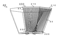
- FIG. 7 shows an outline of the apertured module 20C produced by improving the solid module 20B.
- the module with aperture 20C has a straight upper header 21C and a lower header 22C that is a substantially triangular shape projecting from both ends toward the center in a plan view Z, and a straight line connecting both ends of the lower header 22C.
- the distance is configured to be shorter than a linear distance connecting both ends of the upper header 21C.
- the front view X it becomes a trapezoid in which the length of the lower base is shorter than the upper base.
- the module can be three-dimensionally formed, so that it becomes easy to combine the modules to form a three-dimensional receiver.
- FIG. 8 represents the receiver 2C with the diaphragm by the outer edge of the module 20C with the diaphragm.
- the upper header 21C when the upper header 21C is connected in a circumferential shape, it becomes a polygon (an octagon in FIG. 8) and forms an opening 25 above the receiver 2C with diaphragm. Further, when the lower header 22C is connected in a circumferential shape, it becomes a star shape and forms a bottom surface portion 26 below the receiver 2C.
- this receiver 2C with a diaphragm has narrowed the bottom surface portion 26 with respect to the opening 25, the amount of incident sunlight increases and the area of the bottom surface portion 26 that does not collect solar energy can be reduced. The recovery efficiency can be further improved.
- FIG. 9 shows an outline of the receiver 2C with an aperture.
- FIG. 9 shows a state where a plurality of heat receiving pipes 23 are installed while being shifted from a linear upper header 21C to a bent lower header 22C to constitute a constricted module 20C.
- the shapes of the upper header 21 and the lower header 22 can be arbitrarily selected from any shapes such as a straight shape, a bent shape, and a curved shape.
- the module 20 can be configured by installing a plurality of heat receiving tubes 23 along the shapes of the upper header 21 and the lower header 22.
- the receiver is configured so that the heat header in the module 20 can be quickly recovered by combining the lower header 22 with the upper header 21 facing upward. It is desirable to do.
- This heat insulating material heat radiation of the heat medium h circulating in the module can be prevented.
- FIG. With this configuration, sunlight that passes through the gaps or the like of the heat receiving tube 23 can be reflected to the heat receiving tube 23, so that the solar energy recovery efficiency can be improved.
Landscapes
- Engineering & Computer Science (AREA)
- Physics & Mathematics (AREA)
- Life Sciences & Earth Sciences (AREA)
- Sustainable Development (AREA)
- Sustainable Energy (AREA)
- Thermal Sciences (AREA)
- Chemical & Material Sciences (AREA)
- Combustion & Propulsion (AREA)
- Mechanical Engineering (AREA)
- General Engineering & Computer Science (AREA)
- Photovoltaic Devices (AREA)
- Optical Elements Other Than Lenses (AREA)
Abstract
【課題】 製造コストを低く抑えることができ、故障が発生した場合の復旧作業が容易であり、且つ、緊急時に内部を循環する熱媒体を速やかに回収することができるレシーバー2により、発電コストの抑制を実現した太陽光集光システムを提供することである。 【解決手段】 太陽光Sを、複数のヘリオスタット4から、熱媒体を循環する受熱部2に反射し、前記 熱媒体hからエネルギーを取り出す太陽光集光システム1であって、前記受熱部2を複数のモジュール20の組合せで構成し、前記モジュール20が、上方ヘッダー21と、下方ヘッダー22と、前記2つのヘッダーを連結する複数の受熱管23を有し、且つ、前記モジュール20内を前記熱媒体hが循環するように構成する。
Description
本発明は、複数のヘリオスタット(反射鏡)から反射された太陽光を、レシーバー(受熱部)に集光し、前記レシーバーに熱媒体が循環している太陽光集光システムに関するものである。
近年、石油資源の枯渇及びその価格の高騰が憂慮され、また、地球温暖化の原因の1つである石油資源から新たなエネルギー資源への移行が研究されている。新たなエネルギー源の1つとして、太陽光を集光してエネルギーとして使用する太陽熱発電がある。
太陽光集光システムにおいて、太陽光を反射鏡であるヘリオスタットによりシステム中央部の上方に反射し、この反射光をセンターリフレクターと呼ばれる大型反射鏡で下方に設置されたレシーバー(受熱部)に集光するビームダウン式太陽光集光システムが知られている(例えば、特許文献1参照)。
このレシーバーは、内部で熱媒体(例えば、溶融塩等)が循環するパイプ等で構成することがある。このとき、レシーバーで太陽光から熱エネルギーを受け取った熱媒体は、発電部に送るように構成している。発電部は、例えば、熱媒体の熱を利用して水蒸気を発生させ、この水蒸気を水蒸気タービンに供給して発電を行なう発電装置等で構成している。
この太陽光集光システムを利用した発電の効率を向上させる方法として、集熱レシーバーをつぼ型(キャビティー形状)に構成する発明が開示されている(特許文献2参照)。この特許文献2に記載の発明は、つぼの内部に侵入した太陽光を複数回反射させ、熱媒体に効率的に熱を伝え、太陽光を外部に逃がさないように構成している。この構成により、太陽光発電の効率は非常に高いものとなる。
しかしながら、引用文献2に記載のつぼ型レシーバーは、1本のパイプをつぼ型に成形している構造であるため、製造が非常に困難であり、且つ、製造コストが高くなるという問題を有している。しかも、レシーバーのサイズが巨大となるため、一体型でのレシーバーの運搬は容易ではなく、また、現地で建設する場合も困難な作業となる。
更に、パイプの破損等のレシーバーの故障時には、レシーバー全体を交換する必要がある。ここで、例えば、400~500m四方のビームダウン式太陽光集光システムを建設する場合には、つぼ型のレシーバーの直径は約8~10mとなり、非常に巨大となる。
また、レシーバー内で太陽光があたる部位は不均一であり、温度分布の不均一により、レシーバーを構成するパイプの熱膨張量が不均一となる。このため、レシーバーに隙間が生じたり、窮屈な場所で膨張したりして、場合によってはパイプが割れる等の故障が発生するという問題を有している。
更に、パイプの破損等でレシーバーが故障した場合、レシーバーが1本のパイプにより構成されているため、全体を交換する必要があり、交換作業が大規模となる。加えて、新たなレシーバーを用意するためのコストが嵩むという問題を有している。
更に、太陽光集光システムでは、熱媒体を150~500℃で液相となる硝酸ナトリウム等の溶融塩を使用することが多い。この溶融塩を使用する場合、曇りの日や夜間は、レシーバーから溶融塩を抜き取り、保温槽に移動する必要がある。これは、溶融塩が冷める
と固化し、レシーバー管内で閉塞を起こすためである。この溶融塩を回収する際、引用文献2に記載のらせん状パイプで構成したレシーバーでは、溶融塩を抜くのに時間がかかる。特に、緊急時であり、溶融塩を速やかに回収する必要がある場合に対応することができないという問題がある。
と固化し、レシーバー管内で閉塞を起こすためである。この溶融塩を回収する際、引用文献2に記載のらせん状パイプで構成したレシーバーでは、溶融塩を抜くのに時間がかかる。特に、緊急時であり、溶融塩を速やかに回収する必要がある場合に対応することができないという問題がある。
本発明は、上記の状況を鑑みてなされたものであり、その目的は、製造コスト、運搬コスト及び建設コストを低く抑えることができ、故障が発生した場合の復旧作業が容易であり、且つ、緊急時に内部を循環する熱媒体を速やかに回収することができるレシーバーにより、発電コストの抑制を実現した太陽光集光システムを提供することである。
上記の目的を達成するための本発明に係る太陽光集光システムは、太陽光を、複数のヘリオスタットから、熱媒体を循環する受熱部に反射し、前記熱媒体からエネルギーを取り出す太陽光集光システムであって、前記受熱部を複数のモジュールの組合せで構成し、前記モジュールが、上方ヘッダーと、下方ヘッダーと、前記2つのヘッダーを連結する複数の受熱管を有し、且つ、前記モジュール内を前記熱媒体が循環するように構成したことを特徴とする。
この構成により、受熱管とヘッダーからなる単純なモジュールを組合わせて、レシーバー(受熱部)とすることができるため、製造が容易となる。また、モジュールにばらした状態で運搬できるため、運搬も容易となり、運搬コストを抑制することもできる。また、現地での建設の場合容易に組立が可能となる。更に、パイプ等の破損によるレシーバーの故障時には、レシーバー全体ではなく、その対象となるモジュールのみの交換により修理が完了するため、修理作業が容易となり、交換品のコストも削減することができる。
加えて、複数のモジュールを1つに連結することなく、複数の系統に分けて連結して、太陽光による加熱の不均一を抑制することができる。つまり、温度が上昇しているモジュールの熱媒体の流量を増加し、逆に温度があまり高くないモジュールの熱媒体の流量を減少する制御により、レシーバーにおける温度の不均一さを抑制することができる。
上記の太陽光集光システムにおいて、前記モジュールを、直線状の前記上方ヘッダーと、直線状の前記下方ヘッダーと、前記上方ヘッダーと前記下方ヘッダーを連結する複数の受熱管とで構成し、正面視において略四角形となる平板状モジュールとしたことを特徴とする。
この構成により、モジュールが単純な構成となるため、モジュールの製造コスト、及び運搬コスト等を抑制することができる。
上記の太陽光集光システムにおいて、前記平板状モジュールを、平面視において、前記下方ヘッダーが両端から中心にかけて突出する略三角形となるように構成し、立体型モジュールとしたことを特徴とする。
この構成により、モジュールを立体的な立体型モジュールとすることができる。この複
数の立体型モジュールを組み合わせてレシーバーを構成すると、平板状モジュールを組み合わせた場合とは異なり、入射する太陽光の再反射の効率や、太陽光を外部に漏らさないようにモジュール間の間隔を小さくすること等が可能となり、立体的且つ効率的なレシーバーを構成することができる。特に、熱媒体の流動性の高い直線状の受熱管を使用しながら、モジュールを立体化することができるため、この立体型モジュールにおいて、熱媒体の流動性が低下するという問題は発生しない。
数の立体型モジュールを組み合わせてレシーバーを構成すると、平板状モジュールを組み合わせた場合とは異なり、入射する太陽光の再反射の効率や、太陽光を外部に漏らさないようにモジュール間の間隔を小さくすること等が可能となり、立体的且つ効率的なレシーバーを構成することができる。特に、熱媒体の流動性の高い直線状の受熱管を使用しながら、モジュールを立体化することができるため、この立体型モジュールにおいて、熱媒体の流動性が低下するという問題は発生しない。
上記の太陽光集光システムにおいて、前記立体型モジュールを、平面視において、前記下方ヘッダーの両端を結ぶ直線距離を、前記上方ヘッダーの両端を結ぶ距離より短く構成することを特徴とする。
この構成により、モジュールを、上方ヘッダーから下方ヘッダーにかけて細くなるように絞った、立体型モジュールとすることができる。この絞りの入った立体型モジュールにより、更に、立体的且つ効率的なレシーバーを構成することができる。
上記の太陽光集光システムにおいて、前記受熱部を、平板状に連結した複数の前記平板状モジュールで構成し、それぞれの前記平板状モジュールが、前記上方ヘッダーから前記下方ヘッダーに向かって下降傾斜していることを特徴とする。
この構成により、レシーバー(受熱部)を、平板状モジュールの組み合わせで構成できるため、レシーバーの製造、運搬のコストを抑制することができる。また、上方ヘッダーから下方ヘッダーに向かって傾斜した平板状のレシーバーに構成したことで、緊急時に、モジュール内を循環している熱媒体を容易に回収することができる。
上記の太陽光集光システムにおいて、前記受熱部を、略V字型に連結した複数の前記平板状モジュールで構成し、それぞれの前記平板状モジュールが、前記上方ヘッダーから前記下方ヘッダーに向かって下降傾斜していることを特徴とする。
この構成により、レシーバー(受熱部)に入射した太陽光を、V字型の内側で再反射させることができる。そのため、太陽光のエネルギーを、モジュール内を循環する熱媒体に効率よく伝達することができる。つまり、エネルギーの回収効率を向上することができる。
上記の太陽光集光システムにおいて、前記受熱部を、前記立体モジュールの側部を互いに連結し、つぼ型の受熱部としたことを特徴とする。
この構成により、太陽光のエネルギー回収効率の高いつぼ型のレシーバーを、複数のモジュールの組み合わせで構成することができる。そのため、このつぼ型のレシーバーは、従来と同等のエネルギー回収効率を誇るレシーバーでありながら、製造コスト、運搬コスト及び修繕コストを大幅に抑制したレシーバーとすることができる。
本発明に係る太陽光集光システムによれば、製造コストを低く抑え、故障が発生した場合の復旧作業が容易であり、且つ、緊急時に内部を循環する熱媒体を速やかに回収することができるレシーバーにより、発電コストの抑制を実現した太陽光集光システムを提供することができる。
以下に、本発明に係る実施の形態の太陽光集光システムにおけるレシーバー(受熱部)及びその製造方法について、図面を参照しながら説明する。図1に本発明に係る実施の形態のビームダウン式太陽光集光システム1の構成を示す。なお、以下、ビームダウン式太陽光集光システムに関して説明するが、本発明は、この他にも、タワー型の建造物の上部にレシーバーを設置するタワー式太陽光集光システムに適用することもできる。
まず、太陽光集光システム1の概要について説明する。太陽光集光システム1では、太陽5から照射している太陽光Sを、ヘリオスタット(反射鏡)4で反射し(反射光R1)、センターリフレクター(大型反射鏡)3で再反射し(反射光R2)、レシーバー(受熱部)2に集光する。このレシーバー2の内部では太陽光が反射を繰り返す(反射光R3)。この太陽光の有する熱エネルギーを、レシーバー2を循環する熱媒体で吸収するように構成している。
この熱媒体は、熱媒体用タンク6から、ポンプ7及び熱媒体ライン11を経由して、レシーバー2に供給している。また、レシーバー2で太陽光のエネルギーを吸収した熱媒体は、熱交換器9を経由して、熱媒体用タンク6に戻すように構成している。
この熱交換器9では、水蒸気ライン12を循環する水に、熱媒体の有する熱エネルギーを移動させる。この水(水蒸気)を、水蒸気タービン等を有した水蒸気発電装置10に供給して、発電を行なうように構成している。
また、例えば熱媒体を、硝酸ナトリウム等から構成される溶融塩とした場合、日没後は、全ての溶融塩を熱媒体用タンク6に回収するように制御を行うこともある。これは、日没後にレシーバー2の温度が下がり、溶融塩がレシーバー2内他で固化して、閉塞を起こす問題を回避するためである。
更に、天候の急変(雲天時)やレシーバー2の破損等により、緊急に熱媒体を回収する必要がある場合は、緊急ライン8を利用して、熱媒体用タンク6に熱媒体を回収できるように構成している。ここで、熱媒体用タンク6は、レシーバー2より低い位置に設置することが望ましく、熱媒体を重力により熱媒体用タンク6に回収できる位置関係とすることが望ましい。
次に、ビームダウン式太陽光集光システム1において、発電効率を高め、システムの運搬、設置、及び修繕コストの削減を実現するために、本発明で採用したレシーバー2の構造を説明する。なお、本発明では、レシーバー2を、複数のモジュール20の組み合わせとして構成している。
図2に、レシーバー2を構成するモジュール20の一例として、平板状モジュール20Aを示しており、正面X及び側面Yの概略を示している。この平板状モジュール20Aは、連結管24から受入れた熱媒体hを、上方ヘッダー21Aから受熱管23を経由して、
下方ヘッダー22Aに流し、連結管24から次のモジュールへ供給するように構成している。なお、矢印は熱媒体hの流れを示している。
下方ヘッダー22Aに流し、連結管24から次のモジュールへ供給するように構成している。なお、矢印は熱媒体hの流れを示している。
ここで、連結管24をヘッダー21、22の側方に図示しているが、これはモジュール20Aの連結方向により、上方又は下方に変更することもできる。また、便宜上、受熱管23同士の隙間を空けて図示しているが、この隙間は可能な限り狭い方が、太陽光から熱を回収する効率が上昇する。しかしながら、ビームダウン式太陽光集光システム1において、レシーバー2の温度は600~700℃と高温となることもあるため、受熱管23が膨張して破壊されない程度の隙間をあけておく必要はある。
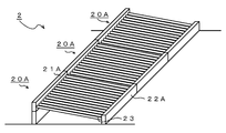
図3に、平板状モジュール20Aを組み合わせて構成したレシーバー2の一例を示す。平板状モジュール20Aを、平面で連結し、上方ヘッダー21Aから下方ヘッダー21Aに若干の傾斜角度を有するように構成している。この傾斜角度は、緊急時に、熱媒体hを動力なしで速やかに回収することが可能となる角度、すなわち、熱媒体hが平板モジュール20A内を自重で流れ落ちる程度の角度である。
この構成により、レシーバー2の製造及び運搬は、複数の平板状モジュール20Aをそれぞれ製造及び運搬することで実現することができる。そのため、直径が8~10mの特許文献2に記載のつぼ型レシーバーに比べ、平板状モジュール20Aは、例えば、横2~4m、縦5~10m程度とすると、運搬性は格段に向上する。また、太陽光集光システム1を建設する現地では、平板状モジュール20Aを組立てる作業によりレシーバー2を作成するため、この作業が容易となり、レシーバー2の運搬コスト及び設置コストを抑制することができる。
また、受熱管23の破損等の故障時には、故障箇所を有する平板状モジュール20Aのみを交換すればよいため、修繕作業が容易、且つ交換部品のコストもモジュール1つ分のみとなるため低コストで行えるようになる。
更に、上方ヘッダー21Aが、下方ヘッダー22Aよりも高い位置になるように設置しているため、緊急時には、受熱管23内を循環している熱媒体hを、容易且つ迅速に回収することが可能となる。
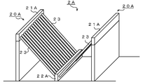
図4に、平板状モジュール20Aを組み合わせて構成したV字型レシーバー2Aの概略を示す。平板状モジュール20Aを、下方ヘッダー22Aで連結し、上方ヘッダー21Aが高い位置になるように組み合わせている。レシーバー2Aの内側に入射した太陽光が再反射して、受熱管23に複数回あたるように構成しているため、太陽エネルギーの回収効率を向上することができる。
なお、図3及び4に示すレシーバー2、2Aにおける平板状モジュール20Aの組み合わせは、これに限られるものではなく、更に多数の平板状モジュール20Aを組み合わせて、レシーバーを構成することができる。例えば、平板状モジュール20Aを、天頂を開放した箱型に組み合わせたり、片側を9枚のモジュール20Aで構成する大型のV字型レシーバーとしたり、平板状モジュール20Aのサイズや、数により、さまざまな組み合わせで、レシーバーを構成することが可能となる。このとき、複数のモジュールを1つに連結することなく、複数の系統に分けて連結して、太陽光による加熱の不均一を抑制することができる。
図5に、平板状モジュール20Aに改良を加えて作製した、立体型モジュール20Bの概略を示す。立体型モジュール20Bは、直線状の上方ヘッダー21Bと、平面視Zにおいて、両端から中心に向かって突出する略三角形となる下方ヘッダー22Bにより構成し
ている。また、正面視Xにおいては略四角形となり、側面視Yにおいては略三角形となる。この屈曲した下方ヘッダー22Bにより、受熱管23は、上方ヘッダー21B近傍では一列に並んだ状態であるが、下方ヘッダー22B近傍では、前後にずれ、曲って並んでいる状態となる。この構成により、モジュールを立体的に形成することができ、このモジュールを組み合わせて立体的なレシーバーを形成することが容易になる。
ている。また、正面視Xにおいては略四角形となり、側面視Yにおいては略三角形となる。この屈曲した下方ヘッダー22Bにより、受熱管23は、上方ヘッダー21B近傍では一列に並んだ状態であるが、下方ヘッダー22B近傍では、前後にずれ、曲って並んでいる状態となる。この構成により、モジュールを立体的に形成することができ、このモジュールを組み合わせて立体的なレシーバーを形成することが容易になる。
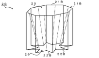
具体的には、図6に示す様に、立体型モジュール20Bの上方ヘッダー21Bを周状に連結し、同様に、下方ヘッダー22Bも周状に連結して、つぼ型レシーバー2Bを構成することができる。図6は、立体型モジュール20Bの外縁により、立体型レシーバー2Bを表現している。
ここで、上方ヘッダー21Bを周状に連結すると、多角形(図6では八角形)となり、つぼ型レシーバー2Bの上方の開口部25を形成する。また、下方ヘッダー22Bを周状に連結すると、星型となり、レシーバー2Bの下方の底面部26を形成する。
このつぼ型レシーバー2Bは、開口部25から入射した太陽光を、レシーバー内で複数回反射することができるため、太陽エネルギーの回収効率を飛躍的に向上することができる。
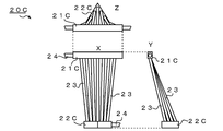
図7に、立体モジュール20Bに改良を加えて作製した、絞り付モジュール20Cの概略を示す。絞り付モジュール20Cは、直線状の上方ヘッダー21Cと、平面視Zにおいて、両端から中心に向かって突出する略三角形となる下方ヘッダー22Cを有しており、更に、下方ヘッダー22Cの両端を結ぶ直線距離を、上方ヘッダー21Cの両端を結ぶ直線距離より短くなるように構成している。また、正面視Xにおいては、上底に比べ下底の長さが短い台形となる。この構成により、モジュールを立体的に形成することができるため、モジュールを組み合わせて立体的なレシーバーを形成することが容易になる。
具体的には、図8に示す様に、絞り付モジュール20Cの上方ヘッダー21Cを周状に連結し、同様に、下方ヘッダー22Cも周状に連結して、絞り付レシーバー2Cを構成することができる。図8は、絞り付モジュール20Cの外縁により、絞り付レシーバー2Cを表現している。
ここで、上方ヘッダー21Cを周状に連結すると、多角形(図8では八角形)となり、絞り付レシーバー2Cの上方の開口部25を形成する。また、下方ヘッダー22Cを周状に連結すると、星型となり、レシーバー2Cの下方の底面部26を形成する。
この絞り付レシーバー2Cは、開口部25に対して、底面部26を細く絞っているため、入射する太陽光が増え、且つ、太陽エネルギーを回収しない底面部26の面積を小さくできるため、太陽エネルギーの回収効率を更に向上することができる。
図9に、絞り付レシーバー2Cの概略を示している。図9は、直線状の上方ヘッダー21Cから、屈曲した下方ヘッダー22Cへ、複数の受熱管23をずらしながら設置し、絞り付モジュール20Cを構成している様子を示している。
なお、モジュール20において、上方ヘッダー21及び下方ヘッダー22の形状は、直線状、屈曲状、又は湾曲状等あらゆる形状を任意に選択することができる。そして、この上方ヘッダー21及び下方ヘッダー22の形状に沿って、複数の受熱管23を設置してモジュール20を構成することができる。また、モジュール20を組み合わせてレシーバーを形成する際には、下方ヘッダー22に対して、上方ヘッダー21が上方となるように組み合わせて、モジュール20内部の熱媒体を速やかに回収できるようにレシーバーを構成
することが望ましい。
することが望ましい。
なお、モジュール20A、20B、20Cの背面(太陽光の受光面と反対側)に、断熱材を設置してもよい。この断熱材により、モジュール内を循環する熱媒体hの放熱を防止することができる。また、モジュール20の背面に、反射鏡を設置する構成としてもよい。この構成により、受熱管23の隙間等を透過する太陽光を、受熱管23に反射することができるため、太陽エネルギーの回収効率を向上することができる。なお、受熱管23上に焦点を持つ放物面を有する反射鏡とすると、更に回収効率を向上することができる。
1 ビームダウン式太陽光集光システム
2 レシーバー(受熱部)
2A V字型レシーバー
2B つぼ型レシーバー
2C 絞り付レシーバー
3 センターリフレクター
4 ヘリオスタット
20 モジュール
20A 平板状モジュール
20B 立体型モジュール
20C 絞り付モジュール
21A、21B、21C 上方ヘッダー
22A、22B、22C 下方ヘッダー
23 受熱管
24 連結管
h 熱媒体
S 太陽光
R1 反射光
R2 再反射光
R3 レシーバー内反射光
2 レシーバー(受熱部)
2A V字型レシーバー
2B つぼ型レシーバー
2C 絞り付レシーバー
3 センターリフレクター
4 ヘリオスタット
20 モジュール
20A 平板状モジュール
20B 立体型モジュール
20C 絞り付モジュール
21A、21B、21C 上方ヘッダー
22A、22B、22C 下方ヘッダー
23 受熱管
24 連結管
h 熱媒体
S 太陽光
R1 反射光
R2 再反射光
R3 レシーバー内反射光
Claims (7)
- 太陽光を、複数のヘリオスタットから熱媒体を循環する受熱部に反射し、前記熱媒体からエネルギーを取り出す太陽光集光システムであって、
前記受熱部を複数のモジュールの組合せで構成し、
前記モジュールが、上方ヘッダーと、下方ヘッダーと、前記2つのヘッダーを連結する複数の受熱管を有し、且つ、前記モジュール内を前記熱媒体が循環するように構成したことを特徴とする太陽光集光システム。 - 前記モジュールを、直線状の前記上方ヘッダーと、直線状の前記下方ヘッダーと、前記上方ヘッダーと前記下方ヘッダーを連結する複数の受熱管とで構成し、正面視において略四角形となる平板状モジュールとしたことを特徴とする請求項1に記載の太陽光集光システム。
- 前記平板状モジュールを、平面視において、前記下方ヘッダーが両端から中心にかけて突出する略三角形となるように構成し、立体型モジュールとしたことを特徴とする請求項2に記載の太陽光集光システム。
- 前記立体型モジュールを、平面視において、前記下方ヘッダーの両端を結ぶ直線距離を、前記上方ヘッダーの両端を結ぶ距離より短く構成することを特徴とする請求項3に記載の太陽光集光システム。
- 前記受熱部を、平板状に連結した複数の前記平板状モジュールで構成し、それぞれの前記平板状モジュールが、前記上方ヘッダーから前記下方ヘッダーに向かって下降傾斜していることを特徴とする請求項2に記載の太陽光集光システム。
- 前記受熱部を、略V字型に連結した複数の前記平板状モジュールで構成し、それぞれの前記平板状モジュールが、前記上方ヘッダーから前記下方ヘッダーに向かって下降傾斜していることを特徴とする請求項2に記載の太陽光集光システム。
- 前記受熱部を、前記立体モジュールの側部を互いに連結し、つぼ型の受熱部としたことを特徴とする請求項3又は4に記載の太陽光集光システム。
Priority Applications (1)
| Application Number | Priority Date | Filing Date | Title |
|---|---|---|---|
| US13/392,249 US8739776B2 (en) | 2009-08-24 | 2010-08-23 | Solar light condensing system |
Applications Claiming Priority (2)
| Application Number | Priority Date | Filing Date | Title |
|---|---|---|---|
| JP2009192671A JP4777452B2 (ja) | 2009-08-24 | 2009-08-24 | 太陽光集光システム |
| JP2009-192671 | 2009-08-24 |
Publications (1)
| Publication Number | Publication Date |
|---|---|
| WO2011024755A1 true WO2011024755A1 (ja) | 2011-03-03 |
Family
ID=43627860
Family Applications (1)
| Application Number | Title | Priority Date | Filing Date |
|---|---|---|---|
| PCT/JP2010/064176 Ceased WO2011024755A1 (ja) | 2009-08-24 | 2010-08-23 | 太陽光集光システム |
Country Status (3)
| Country | Link |
|---|---|
| US (1) | US8739776B2 (ja) |
| JP (1) | JP4777452B2 (ja) |
| WO (1) | WO2011024755A1 (ja) |
Cited By (5)
| Publication number | Priority date | Publication date | Assignee | Title |
|---|---|---|---|---|
| WO2015146701A1 (ja) * | 2014-03-28 | 2015-10-01 | 千代田化工建設株式会社 | 熱媒排出装置 |
| WO2015146700A1 (ja) * | 2014-03-28 | 2015-10-01 | 千代田化工建設株式会社 | 熱媒排出装置 |
| WO2015146698A1 (ja) * | 2014-03-28 | 2015-10-01 | 千代田化工建設株式会社 | 熱媒排出装置および熱媒排出方法 |
| WO2015146699A1 (ja) * | 2014-03-28 | 2015-10-01 | 千代田化工建設株式会社 | 熱媒排出装置および熱媒排出方法 |
| JP2016055241A (ja) * | 2014-09-09 | 2016-04-21 | 旭硝子株式会社 | 樹脂層付き基板の製造装置及び積層体の製造方法並びに電子デバイスの製造方法 |
Families Citing this family (2)
| Publication number | Priority date | Publication date | Assignee | Title |
|---|---|---|---|---|
| JP6279470B2 (ja) * | 2011-09-06 | 2018-02-14 | ビーエーエスエフ ソシエタス・ヨーロピアBasf Se | パイプラインシステム及びパイプラインシステムをドレンする方法 |
| US20160319804A1 (en) * | 2015-04-28 | 2016-11-03 | Elwha Llc | Microchannel solar absorber |
Citations (5)
| Publication number | Priority date | Publication date | Assignee | Title |
|---|---|---|---|---|
| JPS5124434A (en) * | 1974-08-23 | 1976-02-27 | Hitachi Ltd | Taiyonetsu karyokuheiyohatsudensochi |
| JPS5313041A (en) * | 1976-07-22 | 1978-02-06 | Shigeji Sugaya | Solar heat generating unit and its mounting methd |
| JPS58116956U (ja) * | 1982-02-02 | 1983-08-10 | 友常 武久 | 落水勾配付太陽熱集熱器用集熱管 |
| JPS63243463A (ja) * | 1987-03-30 | 1988-10-11 | Agency Of Ind Science & Technol | 発電装置 |
| JP2009150360A (ja) * | 2007-12-21 | 2009-07-09 | Mitsui Eng & Shipbuild Co Ltd | ビームダウン方式太陽熱発電装置 |
Family Cites Families (11)
| Publication number | Priority date | Publication date | Assignee | Title |
|---|---|---|---|---|
| US3924604A (en) * | 1974-05-31 | 1975-12-09 | Schjeldahl Co G T | Solar energy conversion system |
| US4029077A (en) * | 1975-06-13 | 1977-06-14 | Jerry Gorniak | Solar energy collector |
| US4212290A (en) * | 1978-03-06 | 1980-07-15 | Warnken Warren L | Solar collector |
| JPS5838494B2 (ja) | 1980-06-26 | 1983-08-23 | 日本鋼管株式会社 | 焼結鉱の製造法 |
| JPS58116956A (ja) * | 1981-12-29 | 1983-07-12 | Kawasaki Steel Corp | 高珪素薄鋼帯製造用ロ−ル |
| US4485803A (en) * | 1982-10-14 | 1984-12-04 | The Babcock & Wilcox Company | Solar receiver with interspersed panels |
| EP0135664B1 (de) * | 1983-08-31 | 1988-07-27 | GebràDer Sulzer Aktiengesellschaft | Vertikaler Gaszug für einen Wärmeübertrager |
| US4998580A (en) * | 1985-10-02 | 1991-03-12 | Modine Manufacturing Company | Condenser with small hydraulic diameter flow path |
| JP2951297B2 (ja) * | 1997-10-15 | 1999-09-20 | 三鷹光器株式会社 | 太陽光集光システム |
| JP2002310516A (ja) * | 2001-04-10 | 2002-10-23 | Sekisui Chem Co Ltd | 太陽熱集熱装置及び光熱ハイブリッドモジュール |
| JP5011462B2 (ja) | 2004-08-31 | 2012-08-29 | 国立大学法人東京工業大学 | 太陽光集熱器、太陽光集光用反射装置、太陽光集光システムおよび太陽光エネルギ利用システム |
-
2009
- 2009-08-24 JP JP2009192671A patent/JP4777452B2/ja not_active Expired - Fee Related
-
2010
- 2010-08-23 US US13/392,249 patent/US8739776B2/en not_active Expired - Fee Related
- 2010-08-23 WO PCT/JP2010/064176 patent/WO2011024755A1/ja not_active Ceased
Patent Citations (5)
| Publication number | Priority date | Publication date | Assignee | Title |
|---|---|---|---|---|
| JPS5124434A (en) * | 1974-08-23 | 1976-02-27 | Hitachi Ltd | Taiyonetsu karyokuheiyohatsudensochi |
| JPS5313041A (en) * | 1976-07-22 | 1978-02-06 | Shigeji Sugaya | Solar heat generating unit and its mounting methd |
| JPS58116956U (ja) * | 1982-02-02 | 1983-08-10 | 友常 武久 | 落水勾配付太陽熱集熱器用集熱管 |
| JPS63243463A (ja) * | 1987-03-30 | 1988-10-11 | Agency Of Ind Science & Technol | 発電装置 |
| JP2009150360A (ja) * | 2007-12-21 | 2009-07-09 | Mitsui Eng & Shipbuild Co Ltd | ビームダウン方式太陽熱発電装置 |
Cited By (9)
| Publication number | Priority date | Publication date | Assignee | Title |
|---|---|---|---|---|
| WO2015146701A1 (ja) * | 2014-03-28 | 2015-10-01 | 千代田化工建設株式会社 | 熱媒排出装置 |
| WO2015146700A1 (ja) * | 2014-03-28 | 2015-10-01 | 千代田化工建設株式会社 | 熱媒排出装置 |
| WO2015146698A1 (ja) * | 2014-03-28 | 2015-10-01 | 千代田化工建設株式会社 | 熱媒排出装置および熱媒排出方法 |
| WO2015146699A1 (ja) * | 2014-03-28 | 2015-10-01 | 千代田化工建設株式会社 | 熱媒排出装置および熱媒排出方法 |
| JP2015190672A (ja) * | 2014-03-28 | 2015-11-02 | 千代田化工建設株式会社 | 熱媒排出装置および熱媒排出方法 |
| JP2015190671A (ja) * | 2014-03-28 | 2015-11-02 | 千代田化工建設株式会社 | 熱媒排出装置および熱媒排出方法 |
| JP2015190673A (ja) * | 2014-03-28 | 2015-11-02 | 千代田化工建設株式会社 | 熱媒排出装置 |
| JP2015190674A (ja) * | 2014-03-28 | 2015-11-02 | 千代田化工建設株式会社 | 熱媒排出装置 |
| JP2016055241A (ja) * | 2014-09-09 | 2016-04-21 | 旭硝子株式会社 | 樹脂層付き基板の製造装置及び積層体の製造方法並びに電子デバイスの製造方法 |
Also Published As
| Publication number | Publication date |
|---|---|
| US8739776B2 (en) | 2014-06-03 |
| JP2011043127A (ja) | 2011-03-03 |
| JP4777452B2 (ja) | 2011-09-21 |
| US20120152235A1 (en) | 2012-06-21 |
Similar Documents
| Publication | Publication Date | Title |
|---|---|---|
| JP5308275B2 (ja) | 太陽光集光システム | |
| JP4777452B2 (ja) | 太陽光集光システム | |
| CN101903653B (zh) | 光束下射方式太阳热发电装置 | |
| US10288323B2 (en) | Solar receiver with metamaterials-enhanced solar light absorbing structure | |
| JP5898674B2 (ja) | クロスライン型太陽熱集光装置 | |
| US10156383B2 (en) | System of secondary reflectors with high level of efficiency for storage and use of energy from a solar source | |
| US20120132258A1 (en) | Solar collector | |
| KR20140020827A (ko) | 홈통 수집기용 흡수기 튜브 | |
| JP2015106684A (ja) | 太陽光発電システム | |
| WO2011157799A1 (en) | Solar collector assembly with at least one clinching connection, method for manufacturing the solar collector assembly by a clinching mechanism and use of the solar collector assembly | |
| CN110375441B (zh) | 太阳能聚光集热系统 | |
| EP2962047B1 (en) | Solar unit assembly and a method for constructing such an assembly | |
| BR102016017759A2 (pt) | dispositivo de refração solar, e, métodos para fabricar um dispositivo de refração solar e para aquecer um recipiente | |
| CN103299138B (zh) | 具有多管接收器的太阳能集热器,使用所述集热器的太阳能热电站以及用于运行所述电站的方法 | |
| ES1262841U (es) | Instalacion de concentracion solar de tipo cilindro parabolico paracompensar la expansion termica de al menos un tubo colector de calor | |
| CN103944499A (zh) | 光伏发电系统 | |
| RU2611066C2 (ru) | Солнечная электростанция с использованием концентрированного солнечного излучения | |
| KR101378466B1 (ko) | 태양열 집열 장치 | |
| CN103135196A (zh) | 一种反射镜阵列安装装置 | |
| Vir | Solar Booster Augmentation for Existing Coal Fired Power Plant (A Feasibility Study) |
Legal Events
| Date | Code | Title | Description |
|---|---|---|---|
| 121 | Ep: the epo has been informed by wipo that ep was designated in this application |
Ref document number: 10811805 Country of ref document: EP Kind code of ref document: A1 |
|
| NENP | Non-entry into the national phase |
Ref country code: DE |
|
| WWE | Wipo information: entry into national phase |
Ref document number: 13392249 Country of ref document: US |
|
| 122 | Ep: pct application non-entry in european phase |
Ref document number: 10811805 Country of ref document: EP Kind code of ref document: A1 |