WO2011024493A1 - 導電路の屈曲動作ガイド部材及びスライドドア用導電路の屈曲動作ガイド装置 - Google Patents
導電路の屈曲動作ガイド部材及びスライドドア用導電路の屈曲動作ガイド装置 Download PDFInfo
- Publication number
- WO2011024493A1 WO2011024493A1 PCT/JP2010/051834 JP2010051834W WO2011024493A1 WO 2011024493 A1 WO2011024493 A1 WO 2011024493A1 JP 2010051834 W JP2010051834 W JP 2010051834W WO 2011024493 A1 WO2011024493 A1 WO 2011024493A1
- Authority
- WO
- WIPO (PCT)
- Prior art keywords
- guide member
- bending
- conductive path
- bending operation
- hole
- Prior art date
- Legal status (The legal status is an assumption and is not a legal conclusion. Google has not performed a legal analysis and makes no representation as to the accuracy of the status listed.)
- Ceased
Links
Images







Classifications
-
- H—ELECTRICITY
- H02—GENERATION; CONVERSION OR DISTRIBUTION OF ELECTRIC POWER
- H02G—INSTALLATION OF ELECTRIC CABLES OR LINES, OR OF COMBINED OPTICAL AND ELECTRIC CABLES OR LINES
- H02G11/00—Arrangements of electric cables or lines between relatively-movable parts
- H02G11/006—Arrangements of electric cables or lines between relatively-movable parts using extensible carrier for the cable, e.g. self-coiling spring
-
- B—PERFORMING OPERATIONS; TRANSPORTING
- B60—VEHICLES IN GENERAL
- B60R—VEHICLES, VEHICLE FITTINGS, OR VEHICLE PARTS, NOT OTHERWISE PROVIDED FOR
- B60R16/00—Electric or fluid circuits specially adapted for vehicles and not otherwise provided for; Arrangement of elements of electric or fluid circuits specially adapted for vehicles and not otherwise provided for
- B60R16/02—Electric or fluid circuits specially adapted for vehicles and not otherwise provided for; Arrangement of elements of electric or fluid circuits specially adapted for vehicles and not otherwise provided for electric constitutive elements
- B60R16/0207—Wire harnesses
- B60R16/0215—Protecting, fastening and routing means therefor
-
- B—PERFORMING OPERATIONS; TRANSPORTING
- B60—VEHICLES IN GENERAL
- B60R—VEHICLES, VEHICLE FITTINGS, OR VEHICLE PARTS, NOT OTHERWISE PROVIDED FOR
- B60R16/00—Electric or fluid circuits specially adapted for vehicles and not otherwise provided for; Arrangement of elements of electric or fluid circuits specially adapted for vehicles and not otherwise provided for
- B60R16/02—Electric or fluid circuits specially adapted for vehicles and not otherwise provided for; Arrangement of elements of electric or fluid circuits specially adapted for vehicles and not otherwise provided for electric constitutive elements
- B60R16/023—Electric or fluid circuits specially adapted for vehicles and not otherwise provided for; Arrangement of elements of electric or fluid circuits specially adapted for vehicles and not otherwise provided for electric constitutive elements for transmission of signals between vehicle parts or subsystems
- B60R16/027—Electric or fluid circuits specially adapted for vehicles and not otherwise provided for; Arrangement of elements of electric or fluid circuits specially adapted for vehicles and not otherwise provided for electric constitutive elements for transmission of signals between vehicle parts or subsystems between relatively movable parts of the vehicle, e.g. between steering wheel and column
-
- F—MECHANICAL ENGINEERING; LIGHTING; HEATING; WEAPONS; BLASTING
- F16—ENGINEERING ELEMENTS AND UNITS; GENERAL MEASURES FOR PRODUCING AND MAINTAINING EFFECTIVE FUNCTIONING OF MACHINES OR INSTALLATIONS; THERMAL INSULATION IN GENERAL
- F16G—BELTS, CABLES, OR ROPES, PREDOMINANTLY USED FOR DRIVING PURPOSES; CHAINS; FITTINGS PREDOMINANTLY USED THEREFOR
- F16G13/00—Chains
- F16G13/12—Hauling- or hoisting-chains so called ornamental chains
- F16G13/16—Hauling- or hoisting-chains so called ornamental chains with arrangements for holding electric cables, hoses, or the like
-
- H—ELECTRICITY
- H02—GENERATION; CONVERSION OR DISTRIBUTION OF ELECTRIC POWER
- H02G—INSTALLATION OF ELECTRIC CABLES OR LINES, OR OF COMBINED OPTICAL AND ELECTRIC CABLES OR LINES
- H02G3/00—Installations of electric cables or lines or protective tubing therefor in or on buildings, equivalent structures or vehicles
- H02G3/02—Details
- H02G3/04—Protective tubing or conduits, e.g. cable ladders or cable troughs
- H02G3/0462—Tubings, i.e. having a closed section
- H02G3/0475—Tubings, i.e. having a closed section formed by a succession of articulated units
Definitions
- the present invention relates to a technique for guiding a bending operation of a conductive path such as a wire harness for supplying power to an electrical component equipped in a sliding door for an automobile.
- a wire harness is provided between the vehicle body and the sliding door in order to supply power to the electrical components installed in the sliding door for automobiles.
- Various techniques for guiding the bending operation of the wire harness have been proposed in order to suppress the interference between the wire harness and the peripheral member when the sliding door is opened and closed.
- a harness is provided in the slide door, and another harness is provided between the slide door and the vehicle body.
- the harness between the sliding door and the door is configured to be bent mainly along a horizontal plane with respect to the ground, and mainly follows the movement of the sliding door in the front-rear direction and the vehicle width direction.
- a plurality of link members connected so as to be bendable around one axis and configured to be bent as a whole in one plane (referred to as a cable carrier (registered trademark)) ), Or as disclosed in Patent Document 2, a plurality of link members are interconnected by a plurality of types of connection structures, and can be bent three-dimensionally as a whole.
- the movable member to which the harness is connected does not always move within a single plane.
- a part of a sliding door of an automobile may be displaced not only in the vehicle longitudinal direction and the vehicle width direction but also in the vertical direction.
- the so-called cable carrier is basically a structure that can be bent in one plane, and it is difficult to cope with displacement in multiple directions.
- a cable carrier is used as a member that guides the bending operation of the harness between the slide door and the vehicle body, it can follow the movement of the slide door in the front-rear direction and the vehicle width direction, It is difficult to follow the movement.
- an object of the present invention is to make it possible to bend in one plane and to allow bending in a direction substantially perpendicular to the one plane with a simple and low-cost configuration.
- a first aspect is a conductive path bending operation guide member that guides a bending operation of the conductive path in a state of being covered by the conductive path, and a connection hole is formed at one end. And a pair of substantially flat side pieces provided with connection pins that can be disposed in the connection holes at the other end, and a connection support piece for supporting the pair of side pieces with a gap therebetween.
- a plurality of link members, and at least one of the pair of side pieces is fitted in the connection hole in a movable and rotatable state, so that the plurality of link members are linearly formed. It is connected.
- the second aspect is a conductive path bending operation guide member according to the first aspect, wherein the connection pin on one side of the pair of side pieces, or both of the pair of side pieces.
- the connecting pin is fitted into the connecting hole so as to be movable and rotatable.
- a third aspect is a guide operation member for bending a conductive path according to the first or second aspect, wherein the connection pin has a direction component along a connection direction of the plurality of link members in the connection hole. It is arranged to be movable.
- a fourth aspect is a conductive path bending operation guide member according to any one of the first to third aspects, wherein the connection hole is a circular hole larger than the connection pin, and the connection pin is movable.
- the connection hole is a circular hole larger than the connection pin, and the connection pin is movable.
- a long hole or a substantially rectangular hole in which the connecting pin is movable is formed.
- a fifth aspect is a conductive path bending operation guide member according to any one of the first to fourth aspects, wherein the connecting pin is formed in a substantially cylindrical shape.
- a sixth aspect is a conductive operation guide device for a conductive path for a sliding door disposed between a vehicle body and a sliding door, and the conductive path bending operation guide device according to any one of the first to fifth aspects.
- a vehicle body side mounting member connected to one end portion of the bending motion guide member, and a slide door side mounting member connected to the other end portion of the bending motion guide member.
- the slide door-side mounting member is attached to the vehicle body and the slide door in a posture in which the one plane on which the bending operation guide member bends is disposed along a substantially floor surface of the vehicle body.
- each link member is connected so as to be able to be bent around one axis, thereby bending operation.
- the entire guide member can be connected to bendable in one plane.
- the connecting pin is movable in the connecting hole, the bending operation of the bending operation guide member can be permitted even in a direction substantially perpendicular to the one plane within the movable range.
- these operations can be realized by fitting the connecting pins into the connecting holes, a simple and low-cost configuration can be achieved.
- the bending operation guide member depending on how the connection pin is movably and rotatably fitted in the connection hole and applied to the pair of side pieces.
- the bending range of the operation guide member can be controlled.
- the connecting pins of both the pair of side pieces are fitted in the connecting holes so as to be movable and rotatable, the bending range in a direction substantially orthogonal to the one plane is widened.
- the connecting pin on one side of the pair of side pieces is configured to be movable and rotatable in the connecting hole.
- the bending range can be made relatively narrow.
- the bending operation guide member According to the bending operation guide member according to the third aspect, it is easy to bend the bending operation guide member in a direction substantially orthogonal to the one plane in a linear state.
- the connecting pin can be movably fitted into the connecting hole.
- the connecting hole is a circular hole larger than the connecting pin
- the bending operation guide member can be easily bent in a direction substantially orthogonal to the one plane regardless of the relative posture of the adjacent link members.
- the connecting hole is formed in a long hole or a substantially rectangular hole in which the connecting pin can move
- the bending operation guide member can be easily bent in a direction in which the connecting pin can move along the longitudinal direction.
- the connecting pin is easy to rotate in the connecting hole, so that the bending motion guide device bends smoothly in the one plane.
- the movement operation of the sliding door in the front-rear direction and the vehicle width direction can be followed by bending the bending operation guide member in the one plane.
- the vertical movement of the sliding door can be followed by bending the bending movement guide member in a direction substantially orthogonal to the one plane.
- FIG. 3 is a schematic view taken along line III-III in FIG.
- FIG. 1 is a schematic plan view showing the relationship between the vehicle body 12 and the slide door 14
- FIG. 2 is a schematic view taken along line II-II in FIG. 1
- FIG. 3 is a schematic view taken along line III-III in FIG. is there.
- the description may be made with reference to the front-rear direction, the left-right direction, and the up-down direction of the vehicle.
- the automobile 10 has a vehicle body 12 and a slide door 14 provided on one side of the vehicle body 12.
- a boarding opening 13 Through which people can get on and off is provided.
- the slide door 14 is movable between a position where the boarding port 13 is closed (closed position P1) and a position where the boarding port 13 is opened (open position P2) by a slide support mechanism including a guide rail (not shown). It is supported by.
- the slide door 14 is movable between a closed position P1 on the front side of the vehicle and an open position P2 on the rear side of the vehicle by moving mainly in the vehicle front-rear direction.
- the slide door 14 moves from the closed position P1 to the open position P2
- the slide door 14 also moves outward in the vehicle width direction in order to avoid interference with the vehicle body 12.
- the movement amount of the lower end portion of the slide door 14 in the vehicle width direction is set to be larger than the movement amount of the upper end portion of the slide door 14.
- the lower end portion of the slide door 14 moves upward by a dimension H (for example, 10 to 40 mm) when moving from the closed position P1 to the open position P2.
- the bending operation guide member and the bending operation guide device according to the present embodiment are configured to be able to cope with the vertical displacement of the slide door 14.
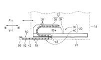
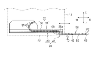
- FIG. 4 and 5 are schematic side views showing the entire configuration of the conductive path device 20 for the sliding door. 4 and 5 are views seen from the inside of the vehicle. FIG. 4 shows a state at the closed position P1, and FIG. 5 shows a state at the open position P2.
- the conductive path device 20 includes various electrical components (for example, a power window drive device, a door lock drive device, and various switches) installed in the slide door 14 and various electrical components (various operation switches, Including a power supply line or a signal line for electrically connecting an electronic control unit, a battery, and the like).
- various electrical components for example, a power window drive device, a door lock drive device, and various switches
- various electrical components variable operation switches, Including a power supply line or a signal line for electrically connecting an electronic control unit, a battery, and the like.
- the first conductive path mechanism unit 30 and the second conductive path mechanism unit 40 are provided. .
- the first conductive path mechanism unit 30 includes an in-door bending operation guide device 32 that guides a bending operation of an in-door wire harness (not shown) as a first conductive path.
- the door bending operation guide device 32 includes a harness guide rail member 34 and a door bending operation guide member 36.
- the harness guide rail member 34 is disposed along the front-rear direction at the lower edge of the slide door 14.
- the in-door bending operation guide member 36 is configured such that a plurality of link members 37 are linearly connected so as to be bent within a predetermined plane (here, a plane substantially parallel to the side surface of the vehicle body).
- a bending operation guide member 52 As the door bending operation guide member 36, a bending operation guide member 52, which will be described later, has a configuration in which a connection pin is fitted only in a rotatable state in the connection hole, or a configuration similar to the bending operation guide member 52. Can be used.
- a movable end 38 a that is movable along the harness guide rail member 34 is attached to one end (lower end) of the in-door bending operation guide member 36. Further, the other end portion (upper end portion) of the in-door bending operation guide member 36 is attached and fixed at a fixed position in the slide door 14.
- the said wire harness in a door is penetrated in the door bending operation
- the end is attached and fixed at a fixed position in the slide door 14.
- the other end part of the wire harness in a door is extended from the other end part of the bending operation guide member 36 in a door, and is further connected to the various electrical components in the slide door 14 via another wire harness etc.
- the wire harness in the door is bent in a plane along the side surface of the vehicle body 12 under the guide state of the harness guide rail member 34 and the door bending operation guide member 36 as the slide door 14 is opened and closed. It has become. More specifically, in the state where the slide door 14 is in the closed position P ⁇ b> 1, the door wire harness and the door bending operation guide member 36 have their respective one ends (lower ends) of the harness guide rail member 34. Of these, it is in a state of being bent in a substantially U shape in a state where it is positioned at the rear of the vehicle (see FIG. 4).
- the door inner wire harness and the door inner bending operation guide member 36 have their respective one ends (lower ends) on the vehicle front side of the harness guide rail member 34. It will be in the state moved to. Thereby, the wire harness in a door and the door bending operation
- movement guide member 36 are made into the substantially J shape which made each linear part of the one end side (lower side) longer than each linear part of the other end side (upper side). A bent state is obtained (see FIG. 5).
- FIG. 6 is an explanatory diagram showing the operation of the second conductive path mechanism unit 40 when viewed from an oblique side of the vehicle
- FIG. 7 shows the operation of the second conductive path mechanism unit 40 when viewed from the inside of the vehicle. It is explanatory drawing.
- the second conductive path mechanism unit 40 is provided between the vehicle body 12 and the slide door 14, and includes a wire harness 42 and a bending motion guide device 50.
- the wiring member provided between the vehicle body 12 and the slide door 14 may be referred to as a transition wiring.
- the wire harness 42 is a structure in which a plurality of electric wires are bundled in a linear shape, and the wire harness 42 is a structure that can be freely bent.
- the bending motion guide device 50 includes a bending motion guide member 52, a vehicle body side mounting member 66, and a slide door side mounting member 68.
- the bending operation guide member 52 is formed in a substantially linear shape, and is configured to guide the bending operation of the wire harness 42 in a state where the bending operation guide member 52 is sheathed on the wire harness 42 that is a conductive path.
- the bending motion guide member 52 is configured to be able to be bent mainly in one plane (here, a plane substantially parallel to the floor surface of the vehicle 12) and bendable in a direction substantially orthogonal to the one plane. .
- the bending range (angle) of the bending operation guide member 52 in the one plane is larger than the bending range (angle) in a direction substantially orthogonal to the one plane.
- the bending motion guide member 52 will be described in detail later.
- the vehicle body side mounting member 66 is connected to one end of the bending motion guide member 52, and is a member that is mounted and fixed to a fixed position of the vehicle body 12 by screwing or fitting structure or the like.
- One end portion of the wire harness 42 is pulled out to the vehicle body 12 side through the vehicle body side mounting member 66 and is connected to various electrical components on the vehicle body 12 side through other wire harnesses not shown.
- the sliding door side mounting member 68 is connected to the other end of the bending motion guide member 52 and is fixedly mounted on the movable end 38a.
- the other end of the wire harness 42 is connected to one end of the in-door wire harness through the slide door side mounting member 68.
- the wire harness 42 and the wire harness in a door may be one continuous wire harness.
- the bending motion guide member 52 is connected to the vehicle body side mounting member 66 and the slide door side mounting member 68 so as to be rotatable around an axis substantially along the vertical direction.
- the vehicle body side mounting member 66 and the slide door side mounting member 68 are arranged such that the one plane on which the bending operation guide member 52 bends is disposed substantially parallel to the floor surface of the vehicle body 12 and the vehicle body 12 and the slide door. 14 respectively.
- the wire harness 42 follows the movement of the slide door 14 under the guide state by the bending operation guide member 52. It bends within the one plane along the floor surface. More specifically, in the state where the slide door 14 is in the closed position P1 (see FIGS. 4, 6, and 7), the wire harness 42 and the bending motion guide member 52 are respectively at the other end portions (the slide door 14 side). Are arranged in a substantially linear posture in which the one end portion (the end portion on the vehicle body 12 side) is arranged in front of the vehicle.
- the other end portions (end portions on the slide door 14 side) of the wire harness 42 and the bending operation guide member 52 move to the vehicle rear side and the vehicle outer side.
- the wire harness 42 and the bending motion guide member 52 go through a form that bends in a substantially U shape, and then connect the other end portion (end portion on the slide door 14 side) to the respective one end portion (the vehicle body 12). It is in an arcuately extended state that is disposed rearward of the vehicle and outward of the vehicle from the side edge.
- the lower end portion of the slide door 14 is also displaced in the vertical direction. Then, with the vertical displacement of the slide door 14, the wire harness 42 is also bent in a direction substantially orthogonal to the one plane under the guide state by the bending operation guide member 52. More specifically, in a state where the slide door 14 is in the closed position P1, the other end portions (the end portions on the slide door 14 side) of the wire harness 42 and the bending operation guide member 52 are their one end portions (of the vehicle body 12). The height dimension H is lower than the end portion (see FIG. 7).
- the lower end of the slide door 14 moves upward and follows the other end of the wire harness 42 and the bending operation guide member 52 (on the slide door 14 side).
- the end portions are also bent in a direction substantially perpendicular to the one plane so as to be positioned at substantially the same height as those one end portions (end portions of the vehicle body 12).
- the wire harness 42 and the bending motion guide member 52 are in a posture extending along a substantially horizontal direction.
- the vertical positional relationship between one end (the end of the vehicle body 12) and the other end (the end on the slide door 14 side) of the wire harness 42 and the bending motion guide member 52 is not limited to the above example.
- both ends of the wire harness 42 and the bending operation guide member 52 are disposed at substantially the same height position
- the slide door 14 is in the open position P2
- the other end portions (end portions on the slide door 14 side) of the harness 42 and the bending operation guide member 52 may be disposed at positions above the one end portions (end portions of the vehicle body 12).
- the relative height relationship between both ends of the wire harness 42 and the bending motion guide member 52 may be changed.
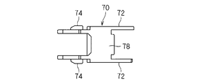
- FIG. 8 is a side view showing the link member 70
- FIG. 9 is a plan view showing the link member 70
- FIG. 10 is a side view showing the link member 70
- FIG. 11 is a bottom view showing the link member 70
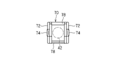
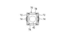
- FIG. 12 is a front view showing the link member 70
- FIG. 13 is a rear view showing the link member 70
- FIG. 14 is an explanatory view showing a connection structure of the link member 70.
- the bending motion guide member 52 has a plurality of link members 70, and the plurality of link members 70 are linearly connected.
- the link member 70 is a member formed of resin or the like, and includes a pair of side pieces 72 and a connection support piece 78 that supports the pair of side pieces 72.
- the side piece 72 is formed in a shape obtained by rounding a corner portion of a substantially rectangular flat plate-like member, and a connection hole 73 is formed at one end portion thereof, and a connection pin 74 is provided at the other end portion. .
- the connection pin 74 is configured to be fitted in the connection hole 73 in a movable and rotatable state.
- the connecting hole 73 is a connecting direction when connecting the plurality of link members 70 (that is, a direction connecting the connecting hole 73 formed in the side piece 72 and the connecting pin 74, and here, the side piece 72. (Longitudinal direction) is formed in a long slot shape.
- the connecting hole 73 is formed in a shape in which semicircular arc-shaped sides are connected to both ends of a pair of substantially parallel opposite sides.
- the connecting hole 73 is not necessarily a through-hole.
- the connecting pin 74 projects from the outer surface side of the side piece 72 and has a substantially columnar convex shape having a diameter substantially the same as the dimension in the short axis direction of the connecting hole 73 (here, a slightly larger diameter). Is formed.
- the connection pin 74 is set as the structure which can be fitted in the connection hole 73 in the state which can move along the said connection direction and can rotate.
- the connecting pin 74 has a partial inclined surface that gradually decreases its height dimension toward the other end of the side piece 72, so that the connecting pin 74 can be smoothly inserted into the connecting hole 73. It can be inserted.
- connection support piece 78 is configured to support the pair of side pieces 72 in a substantially parallel state with a gap between them.
- the connection support pieces 78 are substantially flat members, and a pair of connection support pieces 78 are provided so as to connect and support the outer edges of the pair of side pieces 72.
- the pair of connection pins 74 of the pair of side pieces 72 are coaxially disposed, and the pair of connection holes 73 are also coaxially disposed.
- the substantially square hole-shaped space enclosed by a pair of side piece 72 and a pair of connection support piece 78 is formed, and the wire harness 42 is penetrated in the said space. Yes.
- the outer surface interval of the portion where the connecting pin 74 is formed in the pair of side pieces 72 is formed substantially the same as the inner surface interval of the portion where the connecting hole 73 is formed in the pair of side pieces 72.
- a pair of side piece 72 part in which the connection pin 74 was formed among the link members 70 is arrange
- the protrusion 73a formed around the connection pin 74 and the notch 73b formed around the connection hole 73 regulate the bending allowable range (angle) of the plurality of link members 70. It is a part for. That is, in a state where the plurality of link members 70 are connected as described above, the protrusion 73a is disposed in the notch 73b, and the protrusion 73a is in contact with both ends of the notch 73b. The bending angle of the link member 70 is regulated. The bending angles of the plurality of link members 70 are appropriately set according to the application location of the bending operation guide member 52, the position of the link member 70 in the bending operation guide member 52, and the like.
- the bending operation guide member 52 The operation of the bending operation guide member 52 will be described. First, the plurality of link members 70 bend relatively freely around the axis where the pair of connection pins 74 and the pair of connection holes 73 are connected. As a whole, the bending motion guide member 52 bends relatively freely on one plane substantially orthogonal to the axis. That is, this plane is a plane on which the bending operation guide member 52 is mainly bent.
- the bending motion guide member 52 can be bent in a direction substantially orthogonal to the one plane. That is, as described above, the connecting pin 74 is movable in the connecting hole 73 along the bending direction. Therefore, the link member 70 can be bent in a direction substantially perpendicular to the one plane within a range in which the connection pin 74 can move in the connection hole 73.
- the upper connecting pin 74 is disposed at a position from the outer end portion of the connecting hole 73
- the lower connecting pin 74 is disposed at a position from the inner end portion of the connecting hole 73.
- one link member 70 (right side in FIG.
- the bending between the link members 70 in the above direction is between the outer surface of the portion of the pair of side pieces 72 where the connection pin 74 is formed and the inner surface of the portion of the pair of side pieces 72 where the connection hole 73 is formed. This is performed by utilizing the clearance or elastic deformation of the pair of side pieces 72.
- each link member 70 is moved around the axis of the connecting pin 74 and the connecting hole 73.
- the bending operation guide member 52 can be connected so as to be able to be bent in one plane (here, a substantially horizontal plane substantially parallel to the floor of the vehicle body 12). Thereby, the bending operation guide member 52 can be bent following the movement of the slide door 14 in the horizontal direction, that is, the movement in the vehicle longitudinal direction and the vehicle width direction.
- the bending motion guide member 52 can be moved in a direction substantially perpendicular to the one plane (the vertical direction here) within the movable range. Bending motion is acceptable. Accordingly, the bending operation guide member 52 can be bent following the vertical displacement of the lower end portion of the slide door 14.
- the bending operation guide member 52 can be bent within a range in which the connecting pin 74 can move in the connection hole 73, and the bending range is within a range in which the bending operation guide member 52 bends within the one plane. Compared to small enough. Therefore, the situation where the bending operation guide member 52 hangs down between the vehicle body 12 and the slide door 14 and interferes with other portions is suppressed.
- these operations can be realized by fitting the connecting pins 74 into the connecting holes 73, and basically can be realized by connecting the link members 70 with the same configuration. can do.
- the connecting hole 73 is formed in an elongated hole shape along the connecting direction of the plurality of link members 70, the bending operation guide member 52 is formed in a state where the bending operation guide member 52 extends linearly. It can be bent relatively large in the vertical direction.
- the bending operation guide is moved to the closed position P1 or the opened position P2.
- the member 52 will be in the state extended comparatively linearly. For this reason, there exists an advantage that it is easy to respond
- both the connecting holes 73 of the pair of side pieces 72 are formed in an elongated hole shape, the range in which the bending operation guide member 52 bends in the vertical direction can be made relatively large.
- connecting pin 74 is formed in a columnar shape, it is easy to rotate in the connecting pin 74, and therefore, there is an advantage that the bending operation guide member 52 bends smoothly in the one plane.
- the connecting pin 74 of one (lower) side piece 172a is fitted in the connecting hole 173a so as to be movable and rotatable, and the connecting pin 74 of the other (upper) side piece 172b is connected to the connecting hole 173b. Fits in immovable and rotatable. Therefore, the plurality of link members 170 can move in a direction substantially orthogonal to the one plane within a range in which the connection pin 74 of one (lower) side piece 172a can move in the connection hole 173a.
- the bending range of the link members 70 and 170 depends on how the configuration in which the connection pin 74 is movably fitted in the connection holes 73 and 173a is applied to the pair of side pieces 72, 172a and 172b. Can be controlled.
- only the connecting pin 74 of one side piece 172a is movably fitted into the connecting hole 173a, so that the bending range of the link member 170 is relatively small. can do.
- the degree to which the bending range is set is appropriately set according to the displacement amount of the member to be applied, here, the vertical displacement amount of the lower end portion of the slide door 14.
- the connecting hole 73 is formed in the shape of an elongated hole along the connecting direction of the link member 70, but it is not always necessary, and the connecting pin is fitted in the connecting hole so as to be movable and rotatable. Any configuration may be used.
- the connecting hole 273 may have a larger circular hole shape than the connecting pin 74.
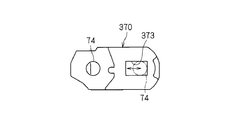
- connection hole 373 may be a substantially rectangular hole shape that is long along the connection direction of the link member 370.
- the link member 370 can be easily bent in the direction in which the connecting pin 74 can move along the longitudinal direction of the connecting hole 373, as in the above embodiment.
- the connecting hole only needs to have a shape that allows the connecting pin to be movably fitted, and may have a shape that is long in a direction oblique to the connecting direction or a direction substantially orthogonal to the connecting direction.
- the connecting pin is at least along the connecting direction of the link member 70 in the connecting hole.
- the directional component is disposed so as to be movable.
- the connecting hole preferably has a long hole shape along the connecting direction, a hole shape that is long in a direction oblique to the connecting direction, a hole shape larger than the connecting pin, and the like.
- the end portion of the pair of side pieces 72 where the connecting pin 74 is formed is aligned with one end side of the link member 70, but this is not always necessary.
- the connection pin 74 of the one side piece 72 and the connection hole 73 of the other side piece 72 may be disposed on one end side of the link member 70.
- the bending motion guide member 52 is described as an example applied to the slide door 14, but this is not always necessary.
- the bending operation guide member 52 itself can be variously applied not only for a sliding door but also for guiding a bending operation of a conductive path disposed between various members that are relatively displaced.
Landscapes
- Engineering & Computer Science (AREA)
- Mechanical Engineering (AREA)
- General Engineering & Computer Science (AREA)
- Electric Cable Arrangement Between Relatively Moving Parts (AREA)
Abstract
ワイヤーハーネスに外装された状態で当該ワイヤーハーネスの屈曲動作をガイドする屈曲動作ガイド部材である。屈曲動作ガイド部材は、一対の側片と、一対の側片をそれらの間に間隔を設けた状態で支持する連結支持片とを有している。一対の側片の一端部には連結穴が形成されると共に、他端部には前記連結穴内に配設可能な連結ピンが設けられている。少なくとも一方の連結ピンが連結穴内に移動可能かつ回転可能な状態で嵌め込まれることで、複数のリンク部材が線状に連結されている。
Description
この発明は、自動車用のスライドドアに装備される電装品に給電を行うワイヤーハーネス等、導電路の屈曲動作をガイドする技術に関する。
自動車用のスライドドアに装備される電装品に給電を行うために、車体とスライドドアとの間にワイヤーハーネスが配設される。スライドドアを開閉動作させる際に、このワイヤーハーネスと周辺部材との干渉を抑制するために、ワイヤーハーネスの屈曲動作をガイドする技術が各種提案されている。
例えば、特許文献1に開示の技術では、スライドドア内にハーネスを設けると共に、スライドドアと車体間にも別のハーネスを配設している。スライドドアとドア間のハーネスは、主として地面に対する水平面に沿って屈曲可能に構成されており、主としてスライドドアの前後方向及び車幅方向への移動に追従動作するようになっている。
ここで、上記ハーネスの屈曲動作をガイドする部材としては、複数のリンク部材を一軸周りに屈曲可能に連結し、全体として一平面内で屈曲可能に構成したもの(ケーブルベヤ(登録商標)と呼ばれるもの)、或は、特許文献2に開示のように、複数のリンク部材を、複数種の連結構造によって相互連結し、全体として3次元的に屈曲可能に構成したもの、等が考えられる。
ところで、ハーネスの接続先となる可動部材は、一平面内でのみ移動するとは限らない。たとえば、自動車のスライドドアの一部は、車両前後方向及び車幅方向だけではなく、上下方向にも変位することもある。
この場合、上記ケーブルベヤと呼ばれるものは、基本的には、一平面内において屈曲可能な構成であり、多方向への変位に対応することは困難である。例えば、ケーブルベヤを、スライドドアと車体間のハーネスの屈曲動作をガイドする部材として用いた場合、スライドドアの前後方向及び車幅方向の移動に追従することはできても、スライドドアの上下方向の移動には追従困難である。
また、特許文献2のように、複数のリンク部材を、複数種の連結構造によって相互連結した構成のものでは、複数種の連結構造を組込む必要があるので、構成の複雑化及び高コスト化を招く恐れがある。
そこで、本発明は、なるべく簡易かつ低コストな構成で、一平面内で屈曲可能にすると共に前記一平面に略直交する方向への屈曲動作も許容できるようにすることを目的とする。
上記課題を解決するため、第1の態様は、導電路に外装された状態で前記導電路の屈曲動作をガイドする導電路の屈曲動作ガイド部材であって、一端部に連結穴が形成されると共に他端部に前記連結穴内に配設可能な連結ピンが設けられた略平板状の一対の側片と、前記一対の側片をそれらの間に間隔を設けた状態で支持する連結支持片とを有する複数のリンク部材を備え、前記一対の側片のうち少なくとも一方の前記連結ピンが前記連結穴に移動可能かつ回転可能な状態で嵌め込まれることで、前記複数のリンク部材が線状に連結されている。
また、第2の態様は、第1の態様に係る導電路の屈曲動作ガイド部材であって、前記一対の側片のうちの一方側の前記連結ピン、或は、前記一対の側片の両方の前記連結ピンが、前記連結穴に移動可能かつ回転可能に嵌め込まれているものである。
第3の態様は、第1又は第2の態様に係る導電路の屈曲動作ガイド部材であって、前記連結ピンは、前記連結穴に、前記複数のリンク部材の連結方向に沿った方向成分を有して移動可能に配設されているものである。
第4の態様は、第1~第3のいずれかの態様に係る導電路の屈曲動作ガイド部材であって、前記連結穴は、前記連結ピンよりも大きな円穴、前記連結ピンが移動可能な長穴、又は、前記連結ピンが移動可能な略長方形穴に形成されているものである。
第5の態様は、第1~第4のいずれかの態様に係る導電路の屈曲動作ガイド部材であって、前記連結ピンは、略円柱状に形成されているものである。
第6の態様は、車体とスライドドアとの間に配設されるスライドドア用導電路の屈曲動作ガイド装置であって、第1~第5のいずれかの態様に係る導電路の屈曲動作ガイド部材と、前記屈曲動作ガイド部材の一端部に連結された車体側取付部材と、前記屈曲動作ガイド部材の他端部に連結されたスライドドア側取付部材と、を備え、前記車体側取付部材及び前記スライドドア側取付部材は、前記屈曲動作ガイド部材が屈曲する前記一平面を車体の略床面に沿って配設した姿勢で、前記車体及び前記スライドドアにそれぞれ取付けられるものである。
第1の態様に係る導電路の屈曲動作ガイド部材によると、前記連結ピンが前記連結穴に回転可能に嵌め込まれているため、各リンク部材を一軸周りに屈曲可能に連結し、もって、屈曲動作ガイド部材全体として一平面内で屈曲可能に連結することができる。この際、連結ピンが連結穴内で移動可能であるため、その移動可能な範囲内で、前記一平面に対して略直交する方向でも、屈曲動作ガイド部材の屈曲動作を許容できる。しかも、これらの動作は、連結ピンを連結穴に嵌め込むことで実現できるため、簡易かつ低コストな構成とすることができる。
第2の態様に係る屈曲動作ガイド部材によると、前記連結ピンが前記連結穴に移動可能かつ回転可能に嵌め込まれた構成を、前記一対の側片に対してどのように適用するかによって、屈曲動作ガイド部材の屈曲範囲をコントロールできる。特に、前記一対の側片の両方の前記連結ピンが、前記連結穴に移動可能かつ回転可能に嵌め込まれた構成とすることで、前記一平面に対して略直交する方向への屈曲範囲を広くすることができ、前記一対の側片のうちの一方側の前記連結ピンが前記連結穴に移動可能かつ回転可能に嵌め込まれた構成とすることで、前記一平面に対して略直交する方向への屈曲範囲を比較的狭くすることができる。
第3の態様に係る屈曲動作ガイド部材によると、直線状態で屈曲動作ガイド部材を前記一平面に対して略直交する方向で屈曲させ易い。
第4の態様によると、連結穴に連結ピンを移動可能に嵌め込むことができる。特に、前記連結穴が前記連結ピンよりも大きな円穴であると、隣接するリンク部材の相対姿勢に拘らず、屈曲動作ガイド部材を前記一平面に対して略直交する方向で屈曲させ易い。また、連結穴が、前記連結ピンが移動可能な長穴又は略長方形穴に形成されていると、連結ピンがその長手方向に沿って移動可能な方向で、屈曲動作ガイド部材を屈曲させ易い。
第5の態様によると、連結ピンは連結穴内で回転し易く、従って、屈曲動作ガイド装置が前記一平面内で円滑に屈曲する。
第6の態様に係るスライドドア用導電路の屈曲動作ガイド装置によると、スライドドアの前後方向及び車幅方向への移動動作については、屈曲動作ガイド部材が前記一平面で屈曲することで追従できる。また、スライドドアの上下方向動作については、屈曲動作ガイド部材が前記一平面に略直交する方向に屈曲することで追従できる。
以下、実施の形態に係る導電路の屈曲動作ガイド部材及びスライドドア用導電路の屈曲動作ガイド装置について説明する。
<適用対象例>
まず、説明の便宜上、適用対象である車体とスライドドアとの関係について説明しておく。図1は車体12とスライドドア14との関係を示す概略平面図であり、図2は図1のII-II線における概略図であり、図3は図1のIII-III線における概略図である。なお、説明の便宜上、車両の前後方向、左右方向、上下方向を参照して説明することがある。
まず、説明の便宜上、適用対象である車体とスライドドアとの関係について説明しておく。図1は車体12とスライドドア14との関係を示す概略平面図であり、図2は図1のII-II線における概略図であり、図3は図1のIII-III線における概略図である。なお、説明の便宜上、車両の前後方向、左右方向、上下方向を参照して説明することがある。
自動車10は、車体12と、車体12の一側部に設けられたスライドドア14とを有している。車体12の一側部には、人が乗降り可能な乗車口13が設けられている。スライドドア14は、図示省略のガイドレールを含むスライド支持機構部によって、前記乗車口13を閉じる位置(閉位置P1)と、乗車口13を開放させる位置(開位置P2)との間で移動可能に支持されている。
より具体的には、スライドドア14は、主として車両前後方向に移動することで、車両前方側の閉位置P1と車両後方側の開位置P2との間で移動可能とされている。このスライドドア14は、閉位置P1から開位置P2に移動する際、車体12との干渉を避けるために、車幅方向において外側にも移動する。この際、車幅方向におけるスライドドア14の下端部の移動量は、スライドドア14の上端部の移動量よりも大きくなるように設定されている。これにより、スライドドア14の下端部は、閉位置P1から開位置P2に移動する際、上方へも寸法H(例えば、10~40mm)程移動するようになっている。本実施形態に係る本屈曲動作ガイド部材及び屈曲動作ガイド装置は、かかるスライドドア14の上下方向への変位にも対応できる構成とされている。
<スライドドア用の導電経路装置の全体構成>
次に、導電路の屈曲動作ガイド部材及びスライドドア用導電路の屈曲動作ガイド装置を適用したスライドドア導電経路装置の全体構成について説明する。
次に、導電路の屈曲動作ガイド部材及びスライドドア用導電路の屈曲動作ガイド装置を適用したスライドドア導電経路装置の全体構成について説明する。
図4及び図5はスライドドア用の導電経路装置20の全体構成を示す概略側面図である。図4及び図5は車両内側から視た図であり、図4は閉位置P1での状態を示しており、図5は開位置P2での状態を示している。
この導電経路装置20は、スライドドア14内に装備された各種電装品(例えば、パワーウインドウの駆動装置、ドアロックの駆動装置、各種スイッチ等)と車体12側の各種電装品(各種操作スイッチ、電子制御ユニット、バッテリ等)とを電気的に接続する電源線或は信号線等を含むものであり、ここでは、第1導電経路機構部30と第2導電経路機構部40とを備えている。
第1導電経路機構部30は、第1導電路としてのドア内ワイヤーハーネス(図示省略)の屈曲動作をガイドするドア内屈曲動作ガイド装置32を有している。ドア内屈曲動作ガイド装置32は、ハーネスガイドレール部材34と、ドア内屈曲動作ガイド部材36とを有している。ハーネスガイドレール部材34は、スライドドア14の下端縁部にその前後方向に沿って配設されている。ドア内屈曲動作ガイド部材36は、複数のリンク部材37を所定の平面(ここでは、車体側面に略平行な平面)内で屈曲可能に線状に連結した構成とされている。ドア内屈曲動作ガイド部材36としては、後述する屈曲動作ガイド部材52において連結ピンを連結穴内に回転可能な状態でのみ嵌め込んだ構成、或は、当該屈曲動作ガイド部材52と同様構成のもの等を用いることができる。また、ドア内屈曲動作ガイド部材36の一端部(下側の端部)に、上記ハーネスガイドレール部材34に沿って移動可能な可動端部38aが取付けられている。また、ドア内屈曲動作ガイド部材36の他端部(上側の端部)がスライドドア14内の一定位置に取付固定されている。そして、上記ドア内ワイヤーハーネスがドア内屈曲動作ガイド部材36内に挿通され、その一端部が可動端部38aによる支持状態下、ハーネスガイドレール部材34に沿って移動可能に支持されると共に、その他端部がスライドドア14内の一定位置に取付固定されている。なお、ドア内ワイヤーハーネスの他端部は、ドア内屈曲動作ガイド部材36の他端部から延出し、さらに他のワイヤーハーネス等を介してスライドドア14内の各種電装品に接続されている。
これにより、ドア内ワイヤーハーネスは、スライドドア14の開閉移動に伴い、ハーネスガイドレール部材34及びドア内屈曲動作ガイド部材36のガイド状態下、車体12の側面に沿った平面内で屈曲するようになっている。より具体的には、スライドドア14が閉位置P1にある状態では、ドア内ワイヤーハーネス及びドア内屈曲動作ガイド部材36は、それぞれの一端部(下側の端部)をハーネスガイドレール部材34のうち車両後方位置に位置させた状態で、略U字状に屈曲した状態となっている(図4参照)。この状態からスライドドア14を開位置P2に移動させると、ドア内ワイヤーハーネス及びドア内屈曲動作ガイド部材36は、それぞれの一端部(下側の端部)をハーネスガイドレール部材34の車両前方側に移動させた状態となる。これにより、ドア内ワイヤーハーネス及びドア内屈曲動作ガイド部材36は、それぞれの一端側(下側)の直線部分をそれぞれの他端側(上側)の直線部分よりも長くした、略J字状に屈曲した状態となる(図5参照)。
図6は車両の斜め側方から視た状態において第2導電経路機構部40の動作を示す説明図であり、図7は車両内側から視た状態において第2導電経路機構部40の動作を示す説明図である。
第2導電経路機構部40は、車体12とスライドドア14との間に設けられており、ワイヤーハーネス42と、屈曲動作ガイド装置50とを備えている。このように、車体12とスライドドア14との間に設けられる配線材は、渡り配線と呼ばれることもある。
図4~図7に示すように、ワイヤーハーネス42は、複数の電線が線状に束ねられたものであり、それ自体は自在に屈曲可能な構成である。
屈曲動作ガイド装置50は、屈曲動作ガイド部材52と、車体側取付部材66と、スライドドア側取付部材68とを有している。
屈曲動作ガイド部材52は、略線状に形成されており、導電路であるワイヤーハーネス42に外装された状態で当該ワイヤーハーネス42の屈曲動作をガイドするように構成されている。ここでは、屈曲動作ガイド部材52は、主として一平面(ここでは車両12の床面と略平行な面)で屈曲可能で、かつ、当該一平面と略直交する方向にも屈曲可能な構成である。なお、前記一平面における屈曲動作ガイド部材52の屈曲範囲(角度)は、前記一平面に略直交する方向における屈曲範囲(角度)よりも大きい。この屈曲動作ガイド部材52については後でさらに詳述する。
また、車体側取付部材66は、上記屈曲動作ガイド部材52の一端部に連結されており、車体12の一定位置にねじ止或は嵌め込み構造等により取付固定される部材である。上記ワイヤーハーネス42の一端部は、車体側取付部材66を通って車体12側に引出され、図示省略の他のワイヤーハーネスを介して車体12側の各種電装品に接続されている。
また、スライドドア側取付部材68は、屈曲動作ガイド部材52の他端部に連結されており、上記可動端部38aに取付固定されている。ワイヤーハーネス42の他端部は、本スライドドア側取付部材68を通って上記ドア内ワイヤーハーネスの一端部に対して接続されている。もっとも、ワイヤーハーネス42とドア内ワイヤーハーネスとは連続する1つのワイヤーハーネスであってもよい。
なお、ここでは、屈曲動作ガイド部材52は、上記車体側取付部材66及びスライドドア側取付部材68により略鉛直方向に沿った軸周りに回転可能に連結されている。また、車体側取付部材66及びスライドドア側取付部材68は、屈曲動作ガイド部材52が屈曲する前記一平面を車体12の床面に対して略平行に配設した姿勢で、車体12及びスライドドア14にそれぞれ取付けられている。
そして、スライドドア14の開閉に伴い、当該スライドドア14が車両前後方向及び車幅方向に移動すると、屈曲動作ガイド部材52によるガイド状態下、当該スライドドア14の移動に追従してワイヤーハーネス42が床面に沿った前記一平面内で屈曲するようになっている。より具体的には、スライドドア14が閉位置P1にある状態(図4、図6、図7参照)では、ワイヤーハーネス42及び屈曲動作ガイド部材52は、それぞれの他端部(スライドドア14側の端部)を、それぞれの一端部(車体12側の端部)よりも車両前方に配設した略直線姿勢に配設されている。この状態からスライドドア14を開位置P2に移動させると、ワイヤーハーネス42及び屈曲動作ガイド部材52の他端部(スライドドア14側の端部)は、車両後方及び車両外側方に移動する。これにより、ワイヤーハーネス42及び屈曲動作ガイド部材52は、略U字状に屈曲する形態を経由した後、それぞれの他端部(スライドドア14側の端部)を、それぞれの一端部(車体12側の端部)よりも車両後方かつ車両外側方に配設した、弧状延在状態となる。
また、上記したように、スライドドア14の開閉に伴い、スライドドア14の下端部は、上下方向にも変位する。すると、当該スライドドア14の上下変位に伴い、屈曲動作ガイド部材52によるガイド状態下、ワイヤーハーネス42も前記一平面に略直交する方向にも屈曲する。より具体的には、スライドドア14が閉位置P1にある状態で、ワイヤーハーネス42及び屈曲動作ガイド部材52の他端部(スライドドア14側の端部)は、それらの一端部(車体12の端部)よりも、高さ寸法H程下方位置にある(図7参照)。そして、スライドドア14が開位置P2に移動すると、スライドドア14の下端部が上方に移動し、これに追従して、ワイヤーハーネス42及び屈曲動作ガイド部材52の他端部(スライドドア14側の端部)は、それらの一端部(車体12の端部)と略同じ高さ位置に位置するように、前記一平面に略直交する方向にも屈曲する。ここでは、この状態で、ワイヤーハーネス42及び屈曲動作ガイド部材52は略水平方向に沿って延在する姿勢となる。
もっとも、ワイヤーハーネス42及び屈曲動作ガイド部材52の一端部(車体12の端部)と他端部(スライドドア14側の端部)との上下位置関係は上記例に限られない。例えば、スライドドア14が閉位置P1にある状態で、ワイヤーハーネス42及び屈曲動作ガイド部材52の両端部が略同じ高さ位置に配設され、スライドドア14が開位置P2にある状態で、ワイヤーハーネス42及び屈曲動作ガイド部材52の他端部(スライドドア14側の端部)が、それらの一端部(車体12の端部)よりも上方位置に配設されてもよい。要するに、スライドドア14の移動に伴い、ワイヤーハーネス42及び屈曲動作ガイド部材52の両端部の相対的な高さ関係が変動すればよい。
<屈曲動作ガイド部材>
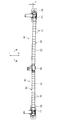
屈曲動作ガイド部材52について説明する。図8はリンク部材70を示す側面図であり、図9はリンク部材70を示す平面図であり、図10はリンク部材70を示す側面図であり、図11はリンク部材70を示す底面図であり、図12はリンク部材70を示す正面図であり、図13はリンク部材70を示す背面図であり、図14はリンク部材70の連結構造を示す説明図である。
屈曲動作ガイド部材52について説明する。図8はリンク部材70を示す側面図であり、図9はリンク部材70を示す平面図であり、図10はリンク部材70を示す側面図であり、図11はリンク部材70を示す底面図であり、図12はリンク部材70を示す正面図であり、図13はリンク部材70を示す背面図であり、図14はリンク部材70の連結構造を示す説明図である。
図7~図14に示すように、屈曲動作ガイド部材52は、複数のリンク部材70を有しており、この複数のリンク部材70が線状に連結された構成とされている。
リンク部材70は、樹脂等により形成された部材であり、一対の側片72と、一対の側片72を支持する連結支持片78とを有している。
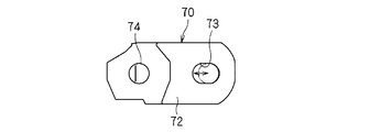
側片72は、略長方形平板状部材のコーナー部を丸めたような形状に形成されており、その一端部に連結穴73が形成されると共に、その他端部に連結ピン74が設けられている。連結ピン74は、連結穴73に移動可能かつ回転可能な状態で嵌め込み可能に構成されている。ここでは、連結穴73は、複数のリンク部材70を連結する際の連結方向(つまり、側片72に形成された連結穴73と連結ピン74とを結ぶ方向であり、ここでは、側片72の長手方向)に沿って長い長穴状に形成されている。より具体的には、連結穴73は、略平行な一対の対辺の両端部に半円弧状辺が連なる形状に形成されている。なお、連結穴73は、必ずしも貫通する孔である必要はない。また、連結ピン74は、側片72の外面側に突出形成されており、連結穴73の短軸方向における寸法と略同一径(ここでは僅かに大きい径)を有する略円柱状の凸部形状に形成されている。そして、連結ピン74が、連結穴73に前記連結方向に沿って移動可能でかつ回転可能な状態で嵌め込み可能な構成とされている。なお、ここでは、連結ピン74は、その高さ寸法を側片72の他端部に向けて徐々に小さくする部分的な傾斜面を有しており、連結ピン74を連結穴73に円滑に嵌め込むことができるようになっている。
また、連結支持片78は、上記一対の側片72を、それらの間に間隔を設けた略並行状態で支持するように構成されている。ここでは、連結支持片78は、略平板状の部材であり、一対の側片72の両外側縁部同士を連結支持するように、一対設けられている。この連結支持状態で、一対の側片72の一対の連結ピン74は同軸上に配設されており、また、一対の連結穴73も同軸上に配設されている。また、各リンク部材70において、一対の側片72と一対の連結支持片78とで囲まれる略方形孔状空間が形成されており、当該空間内にワイヤーハーネス42が挿通されるようになっている。
また、一対の側片72のうち連結ピン74が形成された部分の外面間隔は、一対の側片72のうち連結穴73が形成された部分の内面間隔と略同一に形成されている。そして、リンク部材70のうち連結ピン74が形成された一対の側片72部分を、他のリンク部材のうち連結穴73が形成された一対の側片72部分間に配設して、一対の連結ピン74のそれぞれを一対の連結穴73内に配設することで、複数のリンク部材70が、それら連結ピン74及び連結穴73の軸周りに屈曲可能に連結される構成とされている。
なお、上記一方の側片72のうち連結ピン74周りに形成された突起部73a及び連結穴73周りに形成された切欠部73bは、複数のリンク部材70の屈曲許容範囲(角度)を規制するための部分である。すなわち、複数のリンク部材70が上記のように連結された状態で、突起部73aが切欠部73b内に配設され、突起部73aが切欠部73bの両端部に当接する範囲内で、複数のリンク部材70の屈曲角度が規制されている。複数のリンク部材70の屈曲角度は、本屈曲動作ガイド部材52の適用箇所及び屈曲動作ガイド部材52中におけるリンク部材70の位置等に応じて、適宜設定される。
この屈曲動作ガイド部材52の動作について説明する。まず、複数のリンク部材70は、それぞれの一対の連結ピン74と一対の連結穴73とが連結された軸周りでは比較的自在に屈曲する。全体としてみると、屈曲動作ガイド部材52は、前記軸に略直交する一平面では比較的自在に屈曲する。つまり、この平面が、屈曲動作ガイド部材52が主として屈曲する一平面である。
また、この屈曲動作ガイド部材52は、当該一平面に略直交する方向にも屈曲可能である。つまり、上記したように、連結ピン74は連結穴73内で前記屈曲方向に沿って移動可能である。このため、連結ピン74が連結穴73内を移動可能な範囲内で、リンク部材70は前記一平面に略直交する方向にも屈曲できる。例えば、図14に示すように、上側の連結ピン74を連結穴73の外側端部よりの位置に配設すると共に、下側の連結ピン74を連結穴73の内側端部よりの位置に配設すると、一方のリンク部材70(図14の右側)を他方のリンク部材70(図14の左側)よりも下方にθ度程傾かせるように屈曲させた姿勢にすることができる。かかる動作が複数のリンク部材70間でも行われることで、屈曲動作ガイド部材52全体としてある程度前記一平面に略直交する方向にも屈曲する。また、上記と逆にすることで、屈曲動作ガイド部材52を逆方向にも屈曲させることができる。
なお、上記方向におけるリンク部材70間の屈曲は、一対の側片72のうち連結ピン74が形成された部分の外面と一対の側片72のうち連結穴73が形成された部分の内面との隙間、或は、一対の側片72の弾性変形をも利用して行われる。
以上のように構成された屈曲動作ガイド部材52によると、連結ピン74が連結穴73内に回転可能に嵌め込まれているため、各リンク部材70を、連結ピン74及び連結穴73の軸周りに屈曲可能に連結し、もって、屈曲動作ガイド部材52全体として当該軸に略直交する一平面(ここでは車体12の床面に略平行な略水平面)内で屈曲可能に連結することができる。これにより、スライドドア14の水平方向の移動、つまり、車両前後方向及び車幅方向に移動に追従して屈曲動作ガイド部材52を屈曲させることができる。
この際、連結ピン74が連結穴73内で移動可能であるため、その移動可能な範囲内で、前記一平面に対して略直交する方向(ここでは上下方向)でも、屈曲動作ガイド部材52の屈曲動作を許容できる。これにより、スライドドア14の下端部の上下方向の変位にも追従して、屈曲動作ガイド部材52を屈曲させることができる。なお、屈曲動作ガイド部材52は、連結ピン74が連結穴73内で移動可能な範囲で屈曲可能であり、その屈曲可能な範囲は、屈曲動作ガイド部材52が前記一平面内で屈曲する範囲に比べて、十分に小さい。従って、屈曲動作ガイド部材52が車体12とスライドドア14との間で垂れてしまい、他の部分に干渉するといった事態は抑制されている。
しかも、それらの動作は、連結ピン74を連結穴73に嵌め込むことで実現でき、基本的には、各リンク部材70を同様構成で連結することで実現できるため、簡易かつ低コストな構成とすることができる。
また、連結穴73は、複数のリンク部材70の連結方向に沿って長い長穴状に形成されているため、屈曲動作ガイド部材52が直線状に延びた状態で、当該屈曲動作ガイド部材52を前記上下方向に比較的大きく屈曲させることができる。そして、スライドドア14は、閉位置P1及び開位置P2で、上下方向への変位量が最も大きくなるところ、スライドドア14を閉位置P1或は開位置P2に移動させた状態で、屈曲動作ガイド部材52は比較的直線状に延びた状態となる。このため、スライドドア14の上下変位に対応し易いという利点がある。
また、一対の側片72の連結穴73両方が長穴状に形成されているため、屈曲動作ガイド部材52が上下方向で屈曲する範囲を比較的大きくすることができる。
また、連結ピン74は円柱状に形成されているため、連結ピン74内で回転し易く、従って、屈曲動作ガイド部材52が前記一平面内で円滑に屈曲するという利点がある。
<変形例>
上記実施形態では、一対の側片72の両方の連結ピン74が、それぞれ連結穴73内に移動可能に嵌め込まれている例で説明したが、必ずしもその必要はない。例えば、図15に示すリンク部材170のように、一対の側片172a、172bのうち一方(ここでは下側)の側片172aに上記連結穴73と同様に長穴状の連結穴173aが形成され、他方(ここでは上側)の側片172bに連結ピン74と略同様の大きさの連結穴173bが形成されていてもよい。この場合、一方(下側)の側片172aの連結ピン74だけが連結穴173aに移動可能かつ回転可能に嵌め込まれ、他方(上側)の側片172bの連結ピン74は連結穴173bに対して移動不能かつ回転可能に嵌め込まれる。このため、一方(下側)の側片172aの連結ピン74が連結穴173a内を移動できる範囲内で、複数のリンク部材170が前記一平面に対して略直交する方向に移動できる。
上記実施形態では、一対の側片72の両方の連結ピン74が、それぞれ連結穴73内に移動可能に嵌め込まれている例で説明したが、必ずしもその必要はない。例えば、図15に示すリンク部材170のように、一対の側片172a、172bのうち一方(ここでは下側)の側片172aに上記連結穴73と同様に長穴状の連結穴173aが形成され、他方(ここでは上側)の側片172bに連結ピン74と略同様の大きさの連結穴173bが形成されていてもよい。この場合、一方(下側)の側片172aの連結ピン74だけが連結穴173aに移動可能かつ回転可能に嵌め込まれ、他方(上側)の側片172bの連結ピン74は連結穴173bに対して移動不能かつ回転可能に嵌め込まれる。このため、一方(下側)の側片172aの連結ピン74が連結穴173a内を移動できる範囲内で、複数のリンク部材170が前記一平面に対して略直交する方向に移動できる。
このように、連結ピン74が連結穴73、173aに移動可能に嵌め込まれる構成を、一対の側片72、172a、172bに対してどのように適用するかによって、リンク部材70、170の屈曲範囲をコントロールできる。特に、上記実施形態のように、一対の側片72の両方の連結ピン74がそれぞれ連結穴73に移動可能に嵌め込まれる構成とすることによって、リンク部材70の屈曲範囲を比較的大きくすることができ、また、本変形例のように、一方の側片172aの連結ピン74だけが連結穴173aに移動可能に嵌め込まれる構成とすることによって、リンク部材170の屈曲範囲を比較的小さくするようにすることができる。屈曲範囲をどの程度に設定するかについては、適用対象となる部材の変位量、ここでは、スライドドア14の下端部の上下変位量に応じて適宜設定される。
また、本実施形態では、連結穴73はリンク部材70の連結方向に沿って長い長穴状に形成されているが、必ずしもその必要はなく、連結ピンが連結穴内に移動可能かつ回転可能に嵌め込まれた構成であればよい。
例えば、図16に示すリンク部材270のように、連結穴273は、連結ピン74よりも大きな円穴状であってもよい。これにより、隣接するリンク部材270の相対姿勢に拘らず、即ち、リンク部材270が直線状態であっても相互に屈曲した状態であっても、隣接するリンク部材270を前記一平面に対して略直交する方向に屈曲させ易いという利点がある。
また、例えば、図17に示すリンク部材370のように、連結穴373は、リンク部材370の連結方向に沿って長い略長方形穴状であってもよい。これにより、上記実施形態と同様に、連結ピン74が連結穴373の長手方向に沿って移動可能な方向で、リンク部材370を屈曲させ易い。
上記のように連結穴は、連結ピンを移動可能に嵌め込み可能な形状であればよく、連結方向に対して斜行する方向、或は、略直交する方向に長い穴形状であってもよい。もっとも、リンク部材が直線状に延びた状態で前記一平面に対して略直交する方向で屈曲できるようにするためには、連結ピンは、連結穴内に、少なくともリンク部材70の連結方向に沿った方向成分を有して移動可能に配設されていることが好ましい。例えば、上記のように、連結穴は、連結方向に沿って長い孔形状、連結方向に対して斜行する方向に長い孔形状、連結ピンよりも大きな孔形状等であることが好ましい。
また、上記実施形態では、一対の側片72のうち連結ピン74が形成された側の端部は、リンク部材70の一端側に揃っていたが、必ずしもその必要はない。例えば、リンク部材70の一端側に、一方側の側片72の連結ピン74及び他方側の側片72の連結穴73が配設されていてもよい。
また、本実施形態では、屈曲動作ガイド部材52をスライドドア14に適用した例で説明したが、必ずしもその必要はない。屈曲動作ガイド部材52自体は、スライドドア用だけでなく、相対的に変位する各種部材間に配設される導電路の屈曲動作をガイドするものとして種々適用可能である。
なお、上記実施形態及び各変形例で説明した各構成は、相互に矛盾しない限り適宜組合わせることができる。
以上のようにこの導電路の屈曲動作ガイド部材及びスライドドア用導電路の屈曲動作ガイド装置は詳細に説明されたが、上記した説明は、すべての局面において、例示であって、この発明がそれに限定されるものではない。例示されていない無数の変形例が、この発明の範囲から外れることなく想定され得るものと解される。
Claims (6)
- 導電路に外装された状態で前記導電路の屈曲動作をガイドする導電路の屈曲動作ガイド部材であって、
一端部に連結穴が形成されると共に他端部に前記連結穴内に配設可能な連結ピンが設けられた略平板状の一対の側片と、前記一対の側片をそれらの間に間隔を設けた状態で支持する連結支持片とを有する複数のリンク部材を備え、
前記一対の側片のうち少なくとも一方の前記連結ピンが前記連結穴に移動可能かつ回転可能な状態で嵌め込まれることで、前記複数のリンク部材が線状に連結されている、導電路の屈曲動作ガイド部材。 - 請求項1記載の導電路の屈曲動作ガイド部材であって、
前記一対の側片のうちの一方側の前記連結ピン、或は、前記一対の側片の両方の前記連結ピンが、前記連結穴に移動可能かつ回転可能に嵌め込まれている、導電路の屈曲動作ガイド部材。 - 請求項1記載の導電路の屈曲動作ガイド部材であって、
前記連結ピンは、前記連結穴に、前記複数のリンク部材の連結方向に沿った方向成分を有して移動可能に配設されている、導電路の屈曲動作ガイド部材。 - 請求項1記載の導電路の屈曲動作ガイド部材であって、
前記連結穴は、前記連結ピンよりも大きな円穴、前記連結ピンが移動可能な長穴、又は、前記連結ピンが移動可能な略長方形穴に形成されている、導電路の屈曲動作ガイド部材。 - 請求項1記載の導電路の屈曲動作ガイド部材であって、
前記連結ピンは、略円柱状に形成されている、導電路の屈曲動作ガイド部材。 - 車体とスライドドアとの間に配設されるスライドドア用導電路の屈曲動作ガイド装置であって、
請求項1記載の導電路の屈曲動作ガイド部材と、
前記屈曲動作ガイド部材の一端部に連結された車体側取付部材と、
前記屈曲動作ガイド部材の他端部に連結されたスライドドア側取付部材と、
を備え、
前記車体側取付部材及び前記スライドドア側取付部材は、前記屈曲動作ガイド部材が屈曲する前記一平面を車体の略床面に沿って配設した姿勢で、前記車体及び前記スライドドアにそれぞれ取付けられる、スライドドア用導電路の屈曲動作ガイド装置。
Applications Claiming Priority (2)
| Application Number | Priority Date | Filing Date | Title |
|---|---|---|---|
| JP2009196599A JP2011050182A (ja) | 2009-08-27 | 2009-08-27 | 導電路の屈曲動作ガイド部材及びスライドドア用導電路の屈曲動作ガイド装置 |
| JP2009-196599 | 2009-08-27 |
Publications (1)
| Publication Number | Publication Date |
|---|---|
| WO2011024493A1 true WO2011024493A1 (ja) | 2011-03-03 |
Family
ID=43627607
Family Applications (1)
| Application Number | Title | Priority Date | Filing Date |
|---|---|---|---|
| PCT/JP2010/051834 Ceased WO2011024493A1 (ja) | 2009-08-27 | 2010-02-09 | 導電路の屈曲動作ガイド部材及びスライドドア用導電路の屈曲動作ガイド装置 |
Country Status (2)
| Country | Link |
|---|---|
| JP (1) | JP2011050182A (ja) |
| WO (1) | WO2011024493A1 (ja) |
Families Citing this family (4)
| Publication number | Priority date | Publication date | Assignee | Title |
|---|---|---|---|---|
| JP5640940B2 (ja) * | 2011-09-26 | 2014-12-17 | 住友電装株式会社 | スライドドア用ワイヤハーネスの配索構造 |
| JP2013151250A (ja) * | 2012-01-26 | 2013-08-08 | Sumitomo Wiring Syst Ltd | スライドドアのためのワイヤハーネス配索装置 |
| JP6132309B2 (ja) * | 2013-06-18 | 2017-05-24 | 住友電装株式会社 | 電線ガイド装置 |
| JP7694434B2 (ja) * | 2022-03-30 | 2025-06-18 | 住友電装株式会社 | 電線用可動経路規制部品及び経路規制ワイヤハーネス |
Citations (2)
| Publication number | Priority date | Publication date | Assignee | Title |
|---|---|---|---|---|
| JPS62194093A (ja) * | 1986-02-19 | 1987-08-26 | 株式会社椿本チエイン | ケ−ブル等の可撓支持体 |
| JP2002144876A (ja) * | 2000-11-10 | 2002-05-22 | Nissan Shatai Co Ltd | スライドドアのドアハーネス配索構造 |
-
2009
- 2009-08-27 JP JP2009196599A patent/JP2011050182A/ja active Pending
-
2010
- 2010-02-09 WO PCT/JP2010/051834 patent/WO2011024493A1/ja not_active Ceased
Patent Citations (2)
| Publication number | Priority date | Publication date | Assignee | Title |
|---|---|---|---|---|
| JPS62194093A (ja) * | 1986-02-19 | 1987-08-26 | 株式会社椿本チエイン | ケ−ブル等の可撓支持体 |
| JP2002144876A (ja) * | 2000-11-10 | 2002-05-22 | Nissan Shatai Co Ltd | スライドドアのドアハーネス配索構造 |
Also Published As
| Publication number | Publication date |
|---|---|
| JP2011050182A (ja) | 2011-03-10 |
Similar Documents
| Publication | Publication Date | Title |
|---|---|---|
| US8247921B2 (en) | Power supply apparatus for sliding door | |
| CN101288214B (zh) | 电缆支承装置 | |
| US20130214099A1 (en) | Electric power supply device for sliding door | |
| JP6457992B2 (ja) | 湾曲規制部材及び給電装置 | |
| WO2011024493A1 (ja) | 導電路の屈曲動作ガイド部材及びスライドドア用導電路の屈曲動作ガイド装置 | |
| US20130000941A1 (en) | Power feeding wiring structure | |
| JP3850758B2 (ja) | スライドドアのケーブル配索支持部構造 | |
| US9112342B2 (en) | Power feeding wiring structure | |
| EP2034581B1 (en) | Electric power-feeding structure | |
| JP6112059B2 (ja) | スライドドア用配線装置 | |
| JP6015558B2 (ja) | スライドシート用のワイヤハーネス配索構造 | |
| KR102524310B1 (ko) | 글로브 박스 장치 | |
| JP5418179B2 (ja) | スライドドアおよび給電装置 | |
| JP7430740B2 (ja) | ワイヤハーネス配索構造、リンク式スライドドア、及び、ワイヤハーネス | |
| JP5434556B2 (ja) | ワイヤーハーネス支持具及び導電経路装置 | |
| JP2015110352A (ja) | シート用ワイヤハーネスの配索構造 | |
| JP2005238952A (ja) | スライドドア用給電装置 | |
| JP2007159372A (ja) | ケーブルのガイド装置 | |
| JP5883643B2 (ja) | 引戸連動設備および受け部材 | |
| JP5817309B2 (ja) | ワイヤーハーネス配索装置 | |
| JP2013035331A (ja) | ワイヤーハーネス配索装置 | |
| JP2002127847A (ja) | スライドドアのドアハーネス配索構造 | |
| JP2007274882A (ja) | 給電ユニット | |
| JP5476965B2 (ja) | スライドドア内導電経路装置 | |
| CN118679083A (zh) | 车辆 |
Legal Events
| Date | Code | Title | Description |
|---|---|---|---|
| 121 | Ep: the epo has been informed by wipo that ep was designated in this application |
Ref document number: 10811546 Country of ref document: EP Kind code of ref document: A1 |
|
| NENP | Non-entry into the national phase |
Ref country code: DE |
|
| 122 | Ep: pct application non-entry in european phase |
Ref document number: 10811546 Country of ref document: EP Kind code of ref document: A1 |