WO2011007808A1 - バーナ装置 - Google Patents
バーナ装置 Download PDFInfo
- Publication number
- WO2011007808A1 WO2011007808A1 PCT/JP2010/061915 JP2010061915W WO2011007808A1 WO 2011007808 A1 WO2011007808 A1 WO 2011007808A1 JP 2010061915 W JP2010061915 W JP 2010061915W WO 2011007808 A1 WO2011007808 A1 WO 2011007808A1
- Authority
- WO
- WIPO (PCT)
- Prior art keywords
- air
- region
- fuel mixture
- flame holding
- ignition
- Prior art date
- Legal status (The legal status is an assumption and is not a legal conclusion. Google has not performed a legal analysis and makes no representation as to the accuracy of the status listed.)
- Ceased
Links
Images


Classifications
-
- F—MECHANICAL ENGINEERING; LIGHTING; HEATING; WEAPONS; BLASTING
- F01—MACHINES OR ENGINES IN GENERAL; ENGINE PLANTS IN GENERAL; STEAM ENGINES
- F01N—GAS-FLOW SILENCERS OR EXHAUST APPARATUS FOR MACHINES OR ENGINES IN GENERAL; GAS-FLOW SILENCERS OR EXHAUST APPARATUS FOR INTERNAL-COMBUSTION ENGINES
- F01N3/00—Exhaust or silencing apparatus having means for purifying, rendering innocuous, or otherwise treating exhaust
- F01N3/02—Exhaust or silencing apparatus having means for purifying, rendering innocuous, or otherwise treating exhaust for cooling, or for removing solid constituents of, exhaust
-
- F—MECHANICAL ENGINEERING; LIGHTING; HEATING; WEAPONS; BLASTING
- F23—COMBUSTION APPARATUS; COMBUSTION PROCESSES
- F23M—CASINGS, LININGS, WALLS OR DOORS SPECIALLY ADAPTED FOR COMBUSTION CHAMBERS, e.g. FIREBRIDGES; DEVICES FOR DEFLECTING AIR, FLAMES OR COMBUSTION PRODUCTS IN COMBUSTION CHAMBERS; SAFETY ARRANGEMENTS SPECIALLY ADAPTED FOR COMBUSTION APPARATUS; DETAILS OF COMBUSTION CHAMBERS, NOT OTHERWISE PROVIDED FOR
- F23M9/00—Baffles or deflectors for air or combustion products; Flame shields
- F23M9/06—Baffles or deflectors for air or combustion products; Flame shields in fire-boxes
-
- F—MECHANICAL ENGINEERING; LIGHTING; HEATING; WEAPONS; BLASTING
- F01—MACHINES OR ENGINES IN GENERAL; ENGINE PLANTS IN GENERAL; STEAM ENGINES
- F01N—GAS-FLOW SILENCERS OR EXHAUST APPARATUS FOR MACHINES OR ENGINES IN GENERAL; GAS-FLOW SILENCERS OR EXHAUST APPARATUS FOR INTERNAL-COMBUSTION ENGINES
- F01N3/00—Exhaust or silencing apparatus having means for purifying, rendering innocuous, or otherwise treating exhaust
- F01N3/02—Exhaust or silencing apparatus having means for purifying, rendering innocuous, or otherwise treating exhaust for cooling, or for removing solid constituents of, exhaust
- F01N3/021—Exhaust or silencing apparatus having means for purifying, rendering innocuous, or otherwise treating exhaust for cooling, or for removing solid constituents of, exhaust by means of filters
- F01N3/023—Exhaust or silencing apparatus having means for purifying, rendering innocuous, or otherwise treating exhaust for cooling, or for removing solid constituents of, exhaust by means of filters using means for regenerating the filters, e.g. by burning trapped particles
- F01N3/025—Exhaust or silencing apparatus having means for purifying, rendering innocuous, or otherwise treating exhaust for cooling, or for removing solid constituents of, exhaust by means of filters using means for regenerating the filters, e.g. by burning trapped particles using fuel burner or by adding fuel to exhaust
-
- F—MECHANICAL ENGINEERING; LIGHTING; HEATING; WEAPONS; BLASTING
- F23—COMBUSTION APPARATUS; COMBUSTION PROCESSES
- F23Q—IGNITION; EXTINGUISHING-DEVICES
- F23Q7/00—Incandescent ignition; Igniters using electrically-produced heat, e.g. lighters for cigarettes; Electrically-heated glowing plugs
- F23Q7/22—Details
-
- F—MECHANICAL ENGINEERING; LIGHTING; HEATING; WEAPONS; BLASTING
- F01—MACHINES OR ENGINES IN GENERAL; ENGINE PLANTS IN GENERAL; STEAM ENGINES
- F01N—GAS-FLOW SILENCERS OR EXHAUST APPARATUS FOR MACHINES OR ENGINES IN GENERAL; GAS-FLOW SILENCERS OR EXHAUST APPARATUS FOR INTERNAL-COMBUSTION ENGINES
- F01N2240/00—Combination or association of two or more different exhaust treating devices, or of at least one such device with an auxiliary device, not covered by indexing codes F01N2230/00 or F01N2250/00, one of the devices being
- F01N2240/14—Combination or association of two or more different exhaust treating devices, or of at least one such device with an auxiliary device, not covered by indexing codes F01N2230/00 or F01N2250/00, one of the devices being a fuel burner
-
- F—MECHANICAL ENGINEERING; LIGHTING; HEATING; WEAPONS; BLASTING
- F23—COMBUSTION APPARATUS; COMBUSTION PROCESSES
- F23D—BURNERS
- F23D2900/00—Special features of, or arrangements for burners using fluid fuels or solid fuels suspended in a carrier gas
- F23D2900/21—Burners specially adapted for a particular use
- F23D2900/21003—Burners specially adapted for a particular use for heating or re-burning air or gas in a duct
Definitions
- the present invention relates to a burner device that burns an air-fuel mixture of an oxidant and fuel.
- Fine particles are contained in exhaust gas such as diesel engines. There are concerns about adverse environmental impacts due to the release of these fine particles into the atmosphere. Therefore, in recent years, a filter (DPF) for removing particulates in exhaust gas is installed in a vehicle equipped with a diesel engine or the like.
- This filter is made of ceramic or the like which is a porous body having a plurality of pores smaller than the fine particles. This filter prevents the passage of the fine particles and collects the fine particles.
- Patent Document 1 a burner device is installed between the diesel engine and the filter.
- an air-fuel mixture in which exhaust gas and fuel are mixed is burned to generate high-temperature gas. Fine particles are burned by supplying this high-temperature gas to the filter.
- the fuel injected from the fuel injection device and the exhaust gas or outside air supplied as the oxidant are mixed to generate an air-fuel mixture.
- the mixture is burned by heating the mixture to an ignition temperature or higher with an ignition device. By holding the flame generated by this combustion, the combustion is continued.
- the flow rate of the oxidant or the like supplied to the ignition device is high, the flow rate of the air-fuel mixture supplied to the combustion region is high. In this case, the combustion state in the combustion region may become unstable.
- an object of the present invention is to provide a burner device that can stabilize the combustion state of an air-fuel mixture and can stably generate high-temperature gas.
- the present invention adopts the following configuration as means for solving the above-described problems.
- the 1st invention is the burner apparatus which burns the air-fuel
- the burner device includes a partition member that divides an ignition region for igniting the air-fuel mixture and a flame holding region for maintaining combustion of the air-fuel mixture so that the air-fuel mixture can be ventilated.
- the partition member adjusts the flow rate of the air-fuel mixture supplied from the ignition region to the flame holding region.
- the air-fuel mixture is supplied from the ignition region to the flame holding region so that the partition member collides with an oxidant flow supplied to the flame holding region from the outside. You may ventilate.
- the partition member includes a plurality of through holes that pass through the ignition region and the flame holding region, and the holding member is provided from the ignition region through the through holes.
- the air-fuel mixture may be vented to the flame region.
- the fourth invention may comprise the combustion auxiliary material arranged in the flame holding region in any of the first to third inventions.
- a partition member may be provided that separates at least the flame-holding region from an outer wall in contact with outside air.
- the ignition region and the flame holding region are not separated, the flow rate of the air-fuel mixture supplied to the flame holding region cannot be adjusted.
- the ignition region and the flame holding region are divided by the partition member so that the air-fuel mixture can be ventilated. For this reason, the flow rate of the air-fuel mixture supplied from the ignition region to the flame holding region can be adjusted. That is, the flow rate of the air-fuel mixture supplied to the flame holding region can be adjusted to a flow rate at which combustion is stabilized in the flame holding region. Therefore, according to the burner device of the present invention, the combustion state of the air-fuel mixture can be stabilized, and further, the high temperature gas can be generated stably.
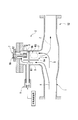
- FIG. 1 is a cross-sectional view showing a schematic configuration of the burner device S1 of the present embodiment.
- the burner device S1 is connected to an exhaust port of a device that exhausts exhaust gas such as a diesel engine disposed on the upstream side.
- the burner device S1 mixes and burns the supplied exhaust gas X (oxidant) and fuel to generate a hot gas Z, and supplies the hot gas Z to the downstream filter.
- the burner device S1 is disposed between, for example, a diesel engine and a particulate filter, and includes a supply flow path 1 and a combustion unit 2.
- the supply channel 1 is a channel for supplying exhaust gas X supplied from a device such as a diesel engine directly to the filter.
- the supply channel 1 is a cylindrical pipe. One end of the supply channel 1 is connected to an exhaust port of a device such as a diesel engine, and the other end is connected to a filter.
- the combustion section 2 is connected to the supply flow path 1.
- the combustion section 2 mixes and burns a part of the exhaust gas X flowing through the supply flow path 1 and the fuel to generate high-temperature gas.
- the combustion unit 2 includes a tube unit 4, a fuel supply unit 5, an ignition device 7, a partition member 8, and an auxiliary combustion air supply device 9.
- the tube part 4 is a tubular member that forms the outer shape of the combustion part 2, and the inside thereof is hollow.
- the tube part 4 is connected to the supply flow path 1 in a direction orthogonal to the extending direction of the supply flow path 1.
- the fuel supply unit 5 includes a fuel holding unit 5a installed at the tip of the ignition device 7, and a supply unit 5b for supplying fuel to the fuel holding unit 5a.
- the fuel holding portion 5a is formed of, for example, a wire mesh, sintered metal, metal fiber, glass cloth, ceramic porous body, ceramic fiber, pumice, or the like.
- the ignition device 7 is composed of a glow plug that is a heater that is heated to a temperature equal to or higher than the ignition temperature of the mixture of fuel and exhaust gas X, and its tip is surrounded by the fuel holding portion 5a.
- the partition member 8 includes an exhaust gas passage region R1 through which the exhaust gas X taken in from the supply passage 1 flows, an ignition region R2 in which the ignition device 7 is installed, and an air-fuel mixture Y. It is divided into a flame holding region R3 where combustion is maintained.
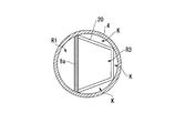
- the partition member 8 extends vertically from the center portion of the tubular body portion 4 and is disposed so as to be spaced apart from the bottom surface of the tubular body portion 4 and horizontally from the central plate 8a as shown in FIG. And a side plate 8b that is spaced apart from the side surface of the tubular body portion 4. The area of the side plate 8b is set wider than the area seen from above the fuel holding portion 5a. As shown in FIG.
- the partition member 8 vents the exhaust gas X from the exhaust gas flow path region R1 to the ignition region R2 through a gap between the center plate 8a and the bottom surface of the tube portion 4, and the side plate 8b and the tube body.
- the air-fuel mixture Y can be ventilated from the ignition region R2 to the flame holding region R3 through a gap with the side surface of the portion 4.
- the partition member 8 is disposed so as to form a gap with the tubular body portion 4, and the air-fuel mixture Y is vented from the ignition region R ⁇ b> 2 to the flame holding region R ⁇ b> 3 through the gap.
- the flow rate of the air-fuel mixture Y is adjusted to a flow rate at which combustion is stabilized in the flame holding region R3.
- the partition member 8 ventilates the air-fuel mixture Y from the lower side to the upper side through a gap opened toward the tubular body part 4. Thereby, the air-fuel mixture Y collides with the flow (oxidant flow) of the exhaust gas X supplied to the flame holding region R3 along the wall surface of the tube body part 4 from above (outside) the flame holding region R3.
- the ventilation area from the exhaust gas flow path region R1 to the ignition region R2 is preferably wider than the ventilation area from the ignition region R2 to the flame holding region R3.
- the ignition region R2 is always filled with gas, the flow rate of the fluid in the ignition region R2 is reduced, and the ignitability is improved.
- the auxiliary combustion air supply device 9 supplies air to the inside (exhaust gas passage region R1) of the tube body 4 as needed.
- the auxiliary combustion air supply device 9 includes an air supply device that supplies air, a pipe that connects the air supply device and the inside of the tubular body portion 4, and the like.
- the exhaust gas X taken from the supply flow path 1 into the exhaust gas flow path region R1 is supplied as an oxidant from the exhaust gas flow path region R1 to the ignition region R2.
- the ignition device 7 is heated under a control device (not shown), and the fuel supplied from the supply unit 5b to the fuel holding unit 5a volatilizes in the ignition region R2. Then, the exhaust gas X supplied to the ignition region R2 and the volatile fuel are mixed to generate an air-fuel mixture Y, and further, the air-fuel mixture Y is ignited by being heated to a temperature equal to or higher than the ignition temperature by the ignition device 7.
- the ventilation area from the exhaust gas flow path region R1 to the ignition region R2 is set wider than the ventilation area from the ignition region R2 to the flame holding region R3.
- the ignition region R2 is always filled with gas, and the flow velocity of the fluid in the ignition region R2 is reduced. Therefore, the air-fuel mixture Y can be easily ignited in the ignition region R2.
- the flame generated by the ignition propagates to the flame holding region R3 together with the unburned air-fuel mixture Y.
- a flame F is formed in the flame holding region R.
- the ignition region R2 and the flame holding region R3 are separated by the partition member 8 so that the air-fuel mixture Y can be vented. Further, the flow rate of the air-fuel mixture Y supplied from the ignition region R2 to the flame holding region R3 is adjusted to a flow rate at which combustion is stabilized in the flame holding region R3. Therefore, according to the burner device S1 of the present embodiment, the combustion state of the air-fuel mixture Y can be stabilized, and further, the hot gas Z can be generated stably.
- the air-fuel mixture Y supplied from the ignition region R2 to the flame holding region R3 collides with the exhaust gas X supplied from above to the flame holding region R3. For this reason, the flow rates of the exhaust gas X and the air-fuel mixture Y can be reduced in the flame holding region R3, and the combustion in the flame holding region R3 can be further stabilized.
- FIG. 3 is a cross-sectional view showing a schematic configuration of the burner device S2 of the present embodiment.
- the burner device S2 of the present embodiment includes a combustion auxiliary material 10 disposed in the flame holding region R3.
- the combustion auxiliary material 10 assists combustion in the flame holding region R3 and suppresses misfire of the flame F.
- the combustion auxiliary material 10 is made of a ceramic porous body that keeps the temperature of the flame holding region at a high temperature by being heated to an ignition temperature or higher by the flame F, or the flame F is misfired by being burned by being heated.
- a suppressing catalyst or the like can be used.
- combustion in the flame holding region R3 is assisted by the combustion auxiliary material 10, so that combustion in the flame holding region R3 can be further stabilized.
- FIG. 4 is a cross-sectional view showing a schematic configuration of the burner device S3 of the present embodiment.
- FIG. 5 is the figure which looked at the tubular-body part with which the burner apparatus of this embodiment is provided from the upper direction.
- the burner device S3 of the present embodiment includes a partition member 20 (partition member) that separates the flame holding region R3 and the wall surface of the tubular body portion 4 that is an outer wall in contact with outside air. Yes.
- the partition member 20 has an open polygonal shape as shown in FIG. 5 when the tubular body portion 4 is viewed from above. Further, the partition member 20 is supported with its apex portion being in contact with the circular tubular body portion 4. Thus, a space K is formed between the partition wall member 20 and the inner wall surface of the tubular body portion 4 in a region excluding the apex portion. By forming such a space K, the flame holding region R3 is separated from the wall surface of the tubular body portion 4.
- the tubular body portion 4 and the flame holding region R3 that are at a low temperature are separated from each other through the space K by being exposed to the outside air by the partition wall member 20. Therefore, it is possible to suppress the cooling of the flame holding region R3 and to stabilize the combustion in the flame holding region R3.
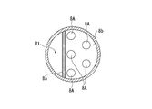
- FIG. 6 is a cross-sectional view showing a schematic configuration of the burner device S4 of the present embodiment, and is a view of the side plate 8b as viewed from above.
- the side plate 8b of the present embodiment includes the entire side wall so as to close the entire region on the flame holding region R3 side in the inner region of the tube part 4 divided in half by the central plate 8a. Connected and touched. Further, a plurality of round holes 8A (through holes) for ventilating the air-fuel mixture Y are formed in the side plate 8b.
- the round holes 8A are formed more on the central plate 8a side (upstream side) and less on the inner wall side (downstream side) of the tube body part 4. Thereby, the opening area by the round hole 8A in the side plate 8b is relatively large on the upstream side in the flow direction of the air-fuel mixture Y, and relatively small on the downstream side.
- the air-fuel mixture Y is supplied to the flame holding region R3 via the narrow circular hole 8A. Therefore, the flow of the air-fuel mixture Y is disturbed, the mixing of the air-fuel mixture Y in the flame holding region R3 is promoted, and good combustion of the air-fuel mixture can be realized.
- the opening area of the side plate 8b is relatively large on the upstream side in the flow direction of the air-fuel mixture Y, and relatively small on the downstream side. For this reason, more air-fuel mixture Y is supplied to the flame holding region R3 from the upstream side of the side plate 8b. As a result, the air-fuel mixture Y can be supplied to the flame holding region R3 without inhibiting the gas flow in the flame holding region R3.
- the upstream opening area of the side plate 8b is preferably about 1.5 times the downstream opening area. Further, the total area of all the round holes 8A is preferably 5 to 20% of the internal cross-sectional area of the tube portion 4a.
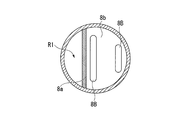
- the round hole 8A was formed as a through-hole, as shown in FIG. 7, you may form the long hole 8B as a through-hole, for example.
- the opening area of the side plate 8b is relatively large on the upstream side in the flow direction of the air-fuel mixture Y and relatively small on the downstream side.
- the upstream long hole 8B in the flow direction of the air-fuel mixture Y is relatively long and the downstream long hole 8B is relatively short.
- the air-fuel mixture Y flows from the ignition region R2 to the flame holding region R3 through a gap formed by separating the side plate 8b from the side surface of the tube part 4.
- the present invention is not limited to this.
- the horizontal cross-sectional shape of the tubular body portion 4 is rectangular, the side plate 8b is brought into contact with the side surface of the tubular body portion 4, and a plurality of through holes 8c are formed in the side plate 8b as shown in FIG.
- the air-fuel mixture Y may be ventilated from the ignition region R2 to the flame holding region R3 through 8c.
- the lateral width of the side plate 8b (the width in the direction perpendicular to the surface of the central plate 8a) ⁇ is 1.1 ⁇ .
- the vertical width (width in the direction along the surface of the central plate 8a) ⁇ of the side plate 8b is 1.0 ⁇ , and the lateral width (width in the direction perpendicular to the surface of the central plate 8a) of the exhaust gas passage region R1 is 0.15 ⁇ or more.
- the vertical width of the exhaust gas passage region R1 (the width in the direction along the surface of the central plate 8a) is ⁇ .
- the diameter of the through hole 8c is set to 0.19 ⁇ (about 8 mm in the experiment), and a total of five of these through holes 8c including the four corners and the central part of the side plate 8b are arranged.
- the center of the through hole 8c arranged at the corner of the side plate 8b is arranged at a position 0.1 ⁇ from the end of the side plate 8b in the horizontal width direction and 0.15 ⁇ from the end of the side plate 8b in the vertical width direction.
- the center of the through hole 8c arranged at the center of the side plate 8b is arranged at 0.3 ⁇ to 0.5 ⁇ from the surface of the center plate 8a and at the center position in the lateral width direction of the side plate 8b.
- combustion in the flame holding region R3 was stabilized even when ten through-holes 8c of 0.14 ⁇ (about 6 mm in the experiment) were formed on the side plate 8b.
- the air-fuel mixture Y may be ventilated from the ignition region R2 to the flame holding region R3 by forming the side plate 8b in a fine mesh shape.
- the auxiliary combustion air supply apparatus 9 is provided. However, when the oxygen concentration contained in the exhaust gas X is sufficiently high, the auxiliary combustion air supply device 9 can be omitted.
- the exhaust gas X is used as the oxidant.
- the present invention is not limited to this, and air may be used as the oxidizing agent.
- the end of the exhaust gas flow path region R1 connected to the supply flow path 1 may be closed, and air may be mainly supplied from the auxiliary combustion air supply device 9 as an oxidant rather than auxiliary.
- the tube part 4 and its internal structure and connection structure may be arranged symmetrically.
- the tubular body portion 4, its internal structure (partition member 8, fuel supply portion 5, ignition device 7, etc.) and connection structure (assisting air supply device 9) are located above the supply flow path 1. It is attached.
- the tubular body portion 4 and its internal structure and connection structure are arranged vertically symmetrically in the burner device S ⁇ b> 1 of the first embodiment.
- the tubular body portion 4 and its internal structure and connection structure may be arranged symmetrically.
- the supply unit 5b connected to the fuel holding unit 5a is used.
- the present invention is not limited to this, and a supply unit that sprays fuel onto the fuel holding unit 5a may be used.
- the ignition region and the flame holding region are divided by the partition member so that the air-fuel mixture can be ventilated.
- the flow rate of the air-fuel mixture supplied from the ignition region to the flame holding region can be adjusted. That is, the flow rate of the air-fuel mixture supplied to the flame holding region can be adjusted to a flow rate at which combustion is stabilized in the flame holding region. Therefore, according to the burner device of the present invention, the combustion state of the air-fuel mixture can be stabilized, and further, the high temperature gas can be generated stably.
- S1 to S4 Burner device, 8... Partition member, 8a... Center plate, 8b.
- DESCRIPTION OF SYMBOLS 10 ... Combustion auxiliary material, 20 ... Partition member, R2 ... Ignition area, R3 ... Flame holding area, X ... Exhaust gas (oxidant), Y ... Mixture, Z ... High temperature gas
Landscapes
- Engineering & Computer Science (AREA)
- Chemical & Material Sciences (AREA)
- Combustion & Propulsion (AREA)
- Mechanical Engineering (AREA)
- General Engineering & Computer Science (AREA)
- Processes For Solid Components From Exhaust (AREA)
Abstract
Description
本願は、2009年07月14日に出願された日本国特許出願第2009-165869号、および2009年09月30日出願された日本国特許出願第2009-226713号に対して優先権を主張し、その内容をここに援用する。
このフィルタは、上記微粒子よりも小さな孔を複数備える多孔質体であるセラミックス等で形成されている。このフィルタにより、上記微粒子の通過を阻止し、微粒子の捕集を行う。
このようなフィルタの目詰まりを防止するために、例えば特許文献1に示されるように、フィルタに対して高温ガスを供給することにより、フィルタに捕集された微粒子を燃焼させて除去する方法が用いられている。
しかしながら、着火装置に供給される酸化剤等の流速が速い場合には、燃焼領域に供給される混合気の流速が速くなる。この場合、燃焼領域における燃焼状態が不安定となる可能性がある。
これに対して、本発明のバーナ装置に、仕切り部材によって、着火領域と保炎領域とが混合気が通気可能に区分けされる。このため、着火領域から保炎領域に供給される混合気の流速を調節することができる。すなわち、保炎領域に供給される混合気の流速を、保炎領域において燃焼が安定化される流速に調節することができる。
従って、本発明のバーナ装置によれば、混合気の燃焼状態を安定化させ、さらには安定して高温ガスの生成を行うことができる。
図1は、本実施形態のバーナ装置S1の概略構成を示す断面図である。
このバーナ装置S1は、上流側に配置されるディーゼルエンジン等の排気ガスを排出する装置の排気口と接続されている。このバーナ装置S1は、供給される排気ガスX(酸化剤)と燃料を混合して燃焼させて高温ガスZを発生させると共に、この高温ガスZを後流側のフィルタに供給する。バーナ装置S1は、例えば、ディーゼルエンジンとパティキュレートフィルタとの間に配置され、供給流路1と、燃焼部2とを備えている。
この仕切り部材8は、図1に示すように、中央板8aと管体部4の底面との隙間によって排気ガス流路領域R1から着火領域R2に排気ガスXを通気し、側板8bと管体部4の側面との隙間によって着火領域R2から保炎領域R3に混合気Yを通気させることができる。
この仕切り部材8は、管体部4との間に隙間を形成して配置され、この隙間によって着火領域R2から保炎領域R3に混合気Yを通気させる。これにより、この混合気Yの流速を、保炎領域R3において燃焼が安定化される流速に調節する。
この仕切り部材8は、管体部4寄りに開口された隙間によって下方から上方に向けて混合気Yを通気させる。これにより、保炎領域R3の上方(外部)から管体部4の壁面に沿って保炎領域R3に供給される排気ガスXの流れ(酸化剤流れ)に、前記混合気Yを衝突させる。
なお、排気ガス流路領域R1から着火領域R2への通気面積は、着火領域R2から保炎領域R3への通気面積よりも広いことが好ましい。これにより、着火領域R2が常に気体で満たされた状態となり、着火領域R2における流体の流速を低減させ、着火性が向上される。
一方で、制御装置(不図示)下において着火装置7が加熱され、供給部5bから燃料保持部5aに供給された燃料が着火領域R2で揮発する。
そして、着火領域R2に供給された排気ガスXと揮発する燃料とが混合されて混合気Yが生成され、さらに着火装置7によって着火温度以上の温度に加熱されることによって混合気Yが着火される。
なお、排気ガス流路領域R1から着火領域R2への通気面積は、着火領域R2から保炎領域R3への通気面積よりも広く設定されている。これにより、着火領域R2が常に気体で満たされた状態となり、着火領域R2における流体の流速が低減される。したがって、着火領域R2において容易に混合気Yに着火することができる。
したがって、本実施形態のバーナ装置S1によれば、混合気Yの燃焼状態を安定化させ、さらには安定して高温ガスZの生成を行うことが可能となる。
次に、本発明の第2実施形態について説明する。なお、本実施形態の説明において、上記第1実施形態と同様の構成については、その説明を省略あるいは簡略化する。
燃焼補助材10は、保炎領域R3における燃焼を補助し、火炎Fの失火を抑制するものである。
この燃焼補助材10には、火炎Fによって着火温度以上に加熱されることによって保炎領域の温度を高温に保つセラミックス多孔体や、加熱されることによって自らが燃焼することによって火炎Fの失火を抑制する触媒等を用いることができる。
次に、本発明の第3実施形態について説明する。なお、本実施形態の説明においても、上記第1実施形態と同様の構成については、その説明を省略あるいは簡略化する。
次に、本発明の第4実施形態について説明する。なお、本実施形態の説明においても、上記第1実施形態と同様の構成については、その説明を省略あるいは簡略化する。
この図に示すように、本実施形態の側板8bは、中央板8aによって半分に仕切られた管体部4の内部領域のうち、保炎領域R3側の領域全体を閉塞するように側壁全体と接続して接触されている。更に、この側板8bには混合気Yを通気するための複数の丸孔8A(貫通孔)が形成されている。
この丸孔8Aは中央板8a側(上流側)に多く、管体部4の内壁側(下流側)に少なく形成されている。これによって、側板8bにおける丸孔8Aによる開口面積は、混合気Yの流れ方向の上流側で相対的に大きく、下流側で相対的に小さくされている。
また、本実施形態のバーナ装置S4では、側板8bにおける開口面積は、混合気Yの流れ方向の上流側で相対的に大きく、下流側で相対的に小さくされている。このため、側板8bの上流側からより多くの混合気Yが保炎領域R3に供給される。この結果、保炎領域R3におけるガス流れを阻害することなく、保炎領域R3に混合気Yを供給することが可能となる。
また、全ての丸孔8Aの面積の総和は、管体部4aの内部断面積の5~20%が望ましい。
この場合でも、側板8bにおける開口面積が、混合気Yの流れ方向の上流側で相対的に大きく、下流側で相対的に小さくなるようにすることが好ましい。また、混合気Yの流れ方向の上流側の長孔8Bを相対的に長く、下流側の長孔8Bを相対的に短くすることが好ましい。
しかしながら、本発明はこれに限定されるものではない。例えば、管体部4の水平断面形状を方形状とし、側板8bを管体部4の側面と接触させ、図8に示すように、側板8bに複数の貫通孔8cを形成し、この貫通孔8cを介して着火領域R2から保炎領域R3に混合気Yを通気しても良い。
このような構成を採用することによって、保炎領域R3における燃焼が安定化する。
また、例えば、側板8bを目の細かいメッシュ状に形成することによって、着火領域R2から保炎領域R3に混合気Yを通気してもよい。
しかしながら、本発明はこれに限定されるものではなく、酸化剤として空気を用いてもよい。
このような場合には、例えば、供給流路1に接続する排気ガス流路領域R1の端部を閉じ、助燃空気供給装置9から、補助的ではなく主として、空気を酸化剤として送り込んでもよい。
なお、図10においては、上記第1実施形態のバーナ装置S1に、管体部4および、その内部構造及び接続構造が、天地対称に配置されている。しかしながら、第2~第4実施形態のバーナ装置S2~S4及びその変形例に対して、管体部4および、その内部構造及び接続構造が、天地対称に配置されていてもよい。
Claims (5)
- 酸化剤と燃料との混合気の燃焼を行うバーナ装置であって、
前記混合気に着火する着火領域と、前記混合気の燃焼を維持する保炎領域と、を前記混合気が通気可能に区分けする仕切り部材を備え、
前記仕切り部材が前記着火領域から前記保炎領域に供給される前記混合気の流速を調節するバーナ装置。 - 前記仕切り部材は、外部から前記保炎領域に供給される酸化剤流れに衝突するように、前記着火領域から前記保炎領域に前記混合気を通気する請求項1記載のバーナ装置。
- 前記仕切り部材は、前記着火領域と前記保炎領域に抜ける複数の貫通孔を備え、前記貫通孔を介して前記着火領域から前記保炎領域に前記混合気を通気する請求項1または2記載のバーナ装置。
- 前記保炎領域に配置される燃焼補助材を備える請求項1に記載のバーナ装置。
- 少なくとも前記保炎領域を、外気と接触する外壁と隔てる隔壁部材を備える請求項1に記載のバーナ装置。
Priority Applications (5)
| Application Number | Priority Date | Filing Date | Title |
|---|---|---|---|
| CN201080031286.XA CN102472490B (zh) | 2009-07-14 | 2010-07-14 | 燃烧器装置 |
| KR1020117031476A KR101358100B1 (ko) | 2009-07-14 | 2010-07-14 | 버너 장치 |
| EP10799866.8A EP2455663B1 (en) | 2009-07-14 | 2010-07-14 | Burner apparatus |
| US13/376,511 US8733085B2 (en) | 2009-07-14 | 2010-07-14 | Burner apparatus |
| CA2767366A CA2767366C (en) | 2009-07-14 | 2010-07-14 | Burner apparatus |
Applications Claiming Priority (4)
| Application Number | Priority Date | Filing Date | Title |
|---|---|---|---|
| JP2009165869 | 2009-07-14 | ||
| JP2009-165869 | 2009-07-14 | ||
| JP2009-226713 | 2009-09-30 | ||
| JP2009226713A JP4720935B2 (ja) | 2009-07-14 | 2009-09-30 | バーナ装置 |
Publications (1)
| Publication Number | Publication Date |
|---|---|
| WO2011007808A1 true WO2011007808A1 (ja) | 2011-01-20 |
Family
ID=43449416
Family Applications (1)
| Application Number | Title | Priority Date | Filing Date |
|---|---|---|---|
| PCT/JP2010/061915 Ceased WO2011007808A1 (ja) | 2009-07-14 | 2010-07-14 | バーナ装置 |
Country Status (7)
| Country | Link |
|---|---|
| US (1) | US8733085B2 (ja) |
| EP (1) | EP2455663B1 (ja) |
| JP (1) | JP4720935B2 (ja) |
| KR (1) | KR101358100B1 (ja) |
| CN (1) | CN102472490B (ja) |
| CA (1) | CA2767366C (ja) |
| WO (1) | WO2011007808A1 (ja) |
Cited By (1)
| Publication number | Priority date | Publication date | Assignee | Title |
|---|---|---|---|---|
| JP2011074819A (ja) * | 2009-09-30 | 2011-04-14 | Ihi Corp | バーナ装置 |
Families Citing this family (2)
| Publication number | Priority date | Publication date | Assignee | Title |
|---|---|---|---|---|
| CN102803850B (zh) * | 2010-03-24 | 2015-03-25 | 株式会社Ihi | 燃烧器装置 |
| FR3002024B1 (fr) * | 2013-02-12 | 2015-02-06 | Jose Cousseau | Installation de production et de traitement de fumees |
Citations (7)
| Publication number | Priority date | Publication date | Assignee | Title |
|---|---|---|---|---|
| JPH0893555A (ja) * | 1994-07-26 | 1996-04-09 | Ishikawajima Harima Heavy Ind Co Ltd | ラム燃焼装置 |
| JPH08233226A (ja) * | 1995-02-24 | 1996-09-10 | Samuson:Kk | 予混合式ガスバーナおよびその着火方法 |
| JP2000110548A (ja) * | 1998-10-01 | 2000-04-18 | Mitsubishi Heavy Ind Ltd | 黒煙除去装置 |
| JP2005265344A (ja) * | 2004-03-19 | 2005-09-29 | Samson Co Ltd | パイロットバーナ部を持った予混合式ガスバーナ |
| JP2007154772A (ja) | 2005-12-06 | 2007-06-21 | Mitsubishi Fuso Truck & Bus Corp | 内燃機関の制御装置 |
| JP2009165869A (ja) | 2009-04-30 | 2009-07-30 | Fujishoji Co Ltd | 遊技機 |
| JP2009226713A (ja) | 2008-03-21 | 2009-10-08 | Seiko Epson Corp | 液体吐出方法、及び液体吐出装置の製造方法 |
Family Cites Families (13)
| Publication number | Priority date | Publication date | Assignee | Title |
|---|---|---|---|---|
| DE3729861C2 (de) | 1987-09-05 | 1995-06-22 | Deutsche Forsch Luft Raumfahrt | Verfahren zum Betreiben einer Rußfiltervorrichtung für einen Dieselmotor und Rußfiltervorrichtung zur Durchführung dieses Verfahrens |
| JPH08580Y2 (ja) | 1989-11-16 | 1996-01-10 | 株式会社ゼクセル | 燃焼式暖房装置 |
| US5379592A (en) * | 1991-10-23 | 1995-01-10 | Waschkuttis; Gerhard | Catalytic converter with ignition burner |
| JP3282944B2 (ja) | 1994-07-18 | 2002-05-20 | トヨタ自動車株式会社 | 低NOxバーナ |
| JP3341800B2 (ja) | 1995-03-23 | 2002-11-05 | イビデン株式会社 | Dpfバーナー再生装置 |
| US5829248A (en) | 1997-06-19 | 1998-11-03 | Environmental Engineering Corp. | Anti-pollution system |
| US6777650B1 (en) * | 2000-02-04 | 2004-08-17 | Saint-Gobtain Industrial Ceramics, Inc. | Igniter shields |
| CA2410725C (en) | 2001-11-16 | 2008-07-22 | Hitachi, Ltd. | Solid fuel burner, burning method using the same, combustion apparatus and method of operating the combustion apparatus |
| AU2003211336A1 (en) * | 2002-02-19 | 2003-09-09 | Yasuo Ajisaka | Diesel exhaust gas purifying filter |
| JP2004324587A (ja) | 2003-04-25 | 2004-11-18 | Mitsubishi Fuso Truck & Bus Corp | 内燃機関の排気浄化装置 |
| DE102004048335B4 (de) * | 2004-10-01 | 2007-04-12 | J. Eberspächer GmbH & Co. KG | Abgasanlage für eine Brennkraftmaschine und zugehöriges Betriebsverfahren |
| KR100748660B1 (ko) * | 2005-12-13 | 2007-08-10 | 현대자동차주식회사 | 디젤 매연 필터의 재생 시스템 및 재생 방법 |
| US20090178394A1 (en) * | 2008-01-15 | 2009-07-16 | Crane Jr Samuel N | Method and Apparatus for Cleaning Electrodes of a Fuel-Fired Burner of an Emission Abatement Assembly |
-
2009
- 2009-09-30 JP JP2009226713A patent/JP4720935B2/ja not_active Expired - Fee Related
-
2010
- 2010-07-14 KR KR1020117031476A patent/KR101358100B1/ko not_active Expired - Fee Related
- 2010-07-14 US US13/376,511 patent/US8733085B2/en not_active Expired - Fee Related
- 2010-07-14 CA CA2767366A patent/CA2767366C/en not_active Expired - Fee Related
- 2010-07-14 WO PCT/JP2010/061915 patent/WO2011007808A1/ja not_active Ceased
- 2010-07-14 CN CN201080031286.XA patent/CN102472490B/zh not_active Expired - Fee Related
- 2010-07-14 EP EP10799866.8A patent/EP2455663B1/en not_active Not-in-force
Patent Citations (7)
| Publication number | Priority date | Publication date | Assignee | Title |
|---|---|---|---|---|
| JPH0893555A (ja) * | 1994-07-26 | 1996-04-09 | Ishikawajima Harima Heavy Ind Co Ltd | ラム燃焼装置 |
| JPH08233226A (ja) * | 1995-02-24 | 1996-09-10 | Samuson:Kk | 予混合式ガスバーナおよびその着火方法 |
| JP2000110548A (ja) * | 1998-10-01 | 2000-04-18 | Mitsubishi Heavy Ind Ltd | 黒煙除去装置 |
| JP2005265344A (ja) * | 2004-03-19 | 2005-09-29 | Samson Co Ltd | パイロットバーナ部を持った予混合式ガスバーナ |
| JP2007154772A (ja) | 2005-12-06 | 2007-06-21 | Mitsubishi Fuso Truck & Bus Corp | 内燃機関の制御装置 |
| JP2009226713A (ja) | 2008-03-21 | 2009-10-08 | Seiko Epson Corp | 液体吐出方法、及び液体吐出装置の製造方法 |
| JP2009165869A (ja) | 2009-04-30 | 2009-07-30 | Fujishoji Co Ltd | 遊技機 |
Non-Patent Citations (1)
| Title |
|---|
| See also references of EP2455663A4 * |
Cited By (1)
| Publication number | Priority date | Publication date | Assignee | Title |
|---|---|---|---|---|
| JP2011074819A (ja) * | 2009-09-30 | 2011-04-14 | Ihi Corp | バーナ装置 |
Also Published As
| Publication number | Publication date |
|---|---|
| KR20120031184A (ko) | 2012-03-30 |
| CA2767366A1 (en) | 2011-01-20 |
| EP2455663B1 (en) | 2013-11-20 |
| US20120096840A1 (en) | 2012-04-26 |
| US8733085B2 (en) | 2014-05-27 |
| JP4720935B2 (ja) | 2011-07-13 |
| JP2011038504A (ja) | 2011-02-24 |
| EP2455663A1 (en) | 2012-05-23 |
| CN102472490A (zh) | 2012-05-23 |
| CN102472490B (zh) | 2014-12-31 |
| CA2767366C (en) | 2014-07-08 |
| EP2455663A4 (en) | 2012-05-23 |
| KR101358100B1 (ko) | 2014-02-04 |
Similar Documents
| Publication | Publication Date | Title |
|---|---|---|
| JP5494795B2 (ja) | バーナ装置 | |
| JP4720935B2 (ja) | バーナ装置 | |
| CN102472491B (zh) | 燃烧器装置 | |
| JP5446741B2 (ja) | バーナ装置 | |
| JP5568996B2 (ja) | バーナ装置 | |
| JP5671794B2 (ja) | バーナ装置 | |
| JP5521465B2 (ja) | バーナ装置 | |
| JP5402474B2 (ja) | バーナ装置 | |
| JP5428712B2 (ja) | バーナ装置 | |
| JP5549915B2 (ja) | バーナ装置 | |
| JP5742128B2 (ja) | バーナ装置 | |
| JP2011099583A (ja) | バーナ装置 |
Legal Events
| Date | Code | Title | Description |
|---|---|---|---|
| WWE | Wipo information: entry into national phase |
Ref document number: 201080031286.X Country of ref document: CN |
|
| 121 | Ep: the epo has been informed by wipo that ep was designated in this application |
Ref document number: 10799866 Country of ref document: EP Kind code of ref document: A1 |
|
| WWE | Wipo information: entry into national phase |
Ref document number: 13376511 Country of ref document: US Ref document number: 2010799866 Country of ref document: EP |
|
| ENP | Entry into the national phase |
Ref document number: 20117031476 Country of ref document: KR Kind code of ref document: A |
|
| WWE | Wipo information: entry into national phase |
Ref document number: 2767366 Country of ref document: CA |
|
| NENP | Non-entry into the national phase |
Ref country code: DE |