WO2011007626A1 - 模型キットおよび模型キットパッケージ - Google Patents
模型キットおよび模型キットパッケージ Download PDFInfo
- Publication number
- WO2011007626A1 WO2011007626A1 PCT/JP2010/059451 JP2010059451W WO2011007626A1 WO 2011007626 A1 WO2011007626 A1 WO 2011007626A1 JP 2010059451 W JP2010059451 W JP 2010059451W WO 2011007626 A1 WO2011007626 A1 WO 2011007626A1
- Authority
- WO
- WIPO (PCT)
- Prior art keywords
- model
- component
- identification display
- display unit
- pattern
- Prior art date
- Legal status (The legal status is an assumption and is not a legal conclusion. Google has not performed a legal analysis and makes no representation as to the accuracy of the status listed.)
- Ceased
Links
Images





Classifications
-
- A—HUMAN NECESSITIES
- A63—SPORTS; GAMES; AMUSEMENTS
- A63H—TOYS, e.g. TOPS, DOLLS, HOOPS OR BUILDING BLOCKS
- A63H33/00—Other toys
- A63H33/04—Building blocks, strips, or similar building parts
-
- G—PHYSICS
- G09—EDUCATION; CRYPTOGRAPHY; DISPLAY; ADVERTISING; SEALS
- G09B—EDUCATIONAL OR DEMONSTRATION APPLIANCES; APPLIANCES FOR TEACHING, OR COMMUNICATING WITH, THE BLIND, DEAF OR MUTE; MODELS; PLANETARIA; GLOBES; MAPS; DIAGRAMS
- G09B19/00—Teaching not covered by other main groups of this subclass
- G09B19/10—Modelling
Definitions
- the present invention relates to a model kit and a model kit package that can be easily assembled.
- Model kits for completing models of automobiles, robots, etc. by assembling model parts made of plastic or the like are known.
- This model component is supported by a runner of one or more model component assembly plates.
- the runner of the model component assembly board is provided with a component identification display section with a number corresponding to each model component in the vicinity of the model component.
- assembly drawing a tool such as nippers It is cut from the assembly board.
- model part assembly plates are included in one model kit.
- model part assembly plates there may be a plurality of model parts with similar shapes such as left and right arms, and in order to assemble without mistake, the model part number indicated in the assembly drawing It is required to assemble and order them neatly while comparing the numbers given to the component identification display section each time.
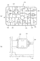
- FIG. 9A is an outline view of the model component assembly plate
- FIG. 9B is an enlarged view of a part of this outline view.
- the model component assembly plate 101 is obtained by integrally molding a plurality of model components 105 via a runner 103 that is a framework of the model component assembly plate 101.
- a part identification display unit 107 is provided as shown in FIG.
- the component identification display unit 107 the component number of each model component 105 is displayed.
- Each model component 105 is separated from the model component assembly plate 101 by cutting the gate portion 109 integrally connected to the runner 103 with a nipper or the like.
- the present invention provides a model kit and a model kit package that can add interest to assembly work in order to solve the above problems. Still another object is to provide a model kit and a model kit package that can be easily assembled without time and effort.
- the model kit of the present invention is a model kit in which a model part is taken from a model part assembly board and a model is assembled, and a pattern or a pattern is displayed on a part identification display part for identifying a model part provided on the model part assembly board. Has been.
- the model kit of the present invention is formed by punching the outline of a pattern or a pattern into a part identification display section.
- the part identification display portion has a shape of a pattern or a pattern.
- the model kit of the present invention preferably displays the model part number on the part identification display unit.
- the constituent material of the model component assembly board on the component identification display unit.
- the design or design is a design or design reminiscent of the silhouette of the character.
- the pattern or pattern is a pattern or pattern that predicts the shape when the model part is assembled.
- model kit package of the present invention is a model kit package in which two or more model kits are bundled, and the pattern or pattern can identify the model assembled and completed by the model parts of the model part assembly board. It is a design or a design to be performed.
- the present invention it is possible to provide a model kit and a model kit package that can add interest to assembly work. Further, according to the present invention, it is possible to provide a model kit and a model kit package that can be easily assembled without taking time and effort.
- Example 1 which is a figure which shows the example which added the symbol which reminds a character to the components identification display part in this invention. It is a figure which shows the example which added the pattern which estimates the shape at the time of an assembly to the components identification display part in this invention (Example 2).
- Example 3) which shows the example which added the symbol which enables the model assembled from the model component of the model component assembly board to be identified to the component identification display part in this invention.
- Example 4 which is the figure which changed the shape of the components identification display part in this invention into the shape which shows the design which reminds a character.
- Example 5 which is the figure which changed the shape of the components identification display part in this invention into the shape which shows the pattern which makes the shape at the time of an assembly
- Example 6 which is the figure which changed the shape of the components identification display part in this invention into the shape which shows the pattern which can identify the model assembled from the model components of the model component assembly board.
- Example 7) which shows the example which displayed the component material of the model component assembly board on the component identification display part.
- Example 8) which is the figure which shows the example formed by punching out the outline of a pattern. It is the figure which showed the conventional model component assembly board.
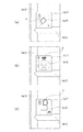
- FIG. 1 is an enlarged view of a component identification display unit provided in the vicinity of each model component.
- FIG. 1A shows a conventional component identification display unit 107
- FIGS. 1B and 1C show an embodiment of the present invention.
- the component identification display unit 1 is formed in a substantially quadrangular shape having an intersection at which the branch 3a and the branch 3b of the runner 3 intersect as one vertex.
- the vertical and horizontal sizes of the component identification display unit 1 are slightly larger than those of the conventional component identification display unit 107 in order to prevent the component number from becoming too small to be seen.
- the conventional component identification display unit 107 is 4.0 mm ⁇ 4.0 mm
- the component identification display unit 1 of the present invention is 6.0 mm ⁇ 6.0 mm. *
- the part identification display unit 1 displays a picture or a pattern (hereinafter, described in a unified manner with the pattern).
- a symbol 5 that recalls the silhouette of a character is displayed.
- a character unrelated to a finished product (not shown) in which model parts are assembled is employed.
- the finished product is “robot” (not shown), and the character is “cat”.
- the symbol 5 displayed on the component identification display unit 1 is reminiscent of the silhouette of the character, but the symbol is a “symbol that predicts the shape when assembling the model component” described later, It may be “a design that allows a plurality of plastic models to be distinguished”.
- a part number (“5” in this example) is displayed on the part identification display unit 1a together with a symbol 5 that reminds the silhouette of the character.
- the pattern 5 is formed by engraving the mold of the assembly plate in advance when the model component assembly plate is molded (formed by scraping the periphery).
- the display unit 1 is formed in a plane, it is formed as a convex part (or a concave part) together with a part number.
- the components identification display part 1a is formed so that a component number may be contained in the silhouette of a character.
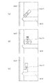
- FIG. 2 is an enlarged view of a component identification display section provided in the vicinity of each model component when the model to be assembled is a robot model.
- the component identification display part 7 is formed in the substantially square shape which makes the intersection which the branch part 3a of the runner 3 and the branch part 3b cross
- the component identification display portion 7a (7) displays a symbol 9a (9) imitating the arm of a robot together with a component number (in this example, “6”). Further, as shown in FIG. 2B, the component identification display portion 7b (7) displays a symbol 9b (9) imitating the robot head together with a component number (in this example, “7”). is there. As shown in FIG. 2C, the component identification display portion 7c (7) displays a symbol 9c (9) imitating the leg of the robot together with a component number (in this example, “8”). In this embodiment, the part number is displayed together with the symbol 9, but only the symbol 9 may be displayed.
- the corresponding part is highlighted and displayed so that the model part (not shown) is the part of the robot.
- the model component corresponds to the forearm ⁇ of the robot arm
- the model component corresponds to the antenna ⁇ of the robot head.
- the model component corresponds to the thigh ⁇ of the leg portion of the robot.
- the component identification display unit 7 has a left side. "L” is displayed on each arm and leg, and “R” is displayed on the right arm and leg.
- the part identification display unit 7 displays the symbol 9 that predicts the shape when the model part (not shown) is assembled together with the part number (in this example, “6”, “7”, “8”). ing. That is, the model part with the number “6” displayed on the part identification display unit 7a can be easily predicted to be one part of the robot arm, and the number “7” displayed on the part identification display unit 7b. The model part with the number “8” displayed on the part identification display part 7c is one part of the leg part of the robot. Can easily be expected.
- the pattern 9 for predicting the shape when the model part is assembled is formed by engraving the mold of the assembly board in advance when the model part assembly board is molded (by cutting off the periphery).
- the component identification display portion 7 is formed on a flat surface, whereas it is formed as a convex portion (or a concave portion) together with the component number.
- the forearm ⁇ , the antenna ⁇ , and the thigh ⁇ that are displayed with emphasis are convex portions, they can be formed by widening the groove width carved into the mold. In the case of a recessed part, it can form by reducing the part scraped off from a metal mold
- the part number is displayed at the corner of the rectangle constituting the part identification display unit 7.
- the part number may be displayed in the pattern 9 so that the part number is contained, or You may display in the approximate center.
- the component identification display unit 7 when there are a large number of model component assembly plates, the shape when assembling the model components cut out from each model component assembly plate can be predicted, When cutting and assembling, it is not necessary to check the assembly drawing each time, so the model can be assembled easily.
- FIG. 3 is an enlarged view of a component identification display portion provided in the vicinity of each model component in a model component assembly plate in a model kit package in which two or more model kits are bundled.
- the component identification display part 11 is formed in the substantially square shape which makes the intersection which the branch part 3a of the runner 3 and the branch part 3b cross
- the identification display unit 11 displays a pattern 13 that enables identification of a model assembled from model parts of the model part assembly board.
- the component identification display unit 11a (11) displays a symbol 13a (13) indicating a tank model together with a component number (in this example, “9”). Further, as shown in FIG. 3B, the component identification display unit 11b (11) displays a symbol 13b (13) indicating a model of a fighter aircraft together with a component number (in this example, “10”). Further, as shown in FIG. 3C, a symbol 13c (13) indicating a submarine model is displayed on the component identification display portion 11c (11) together with a component number (in this example, “11”). In this embodiment, the part number is displayed together with the symbol 13, but only the symbol 13 may be displayed.
- FIG. 4 is a diagram showing an example in which the shape of the component identification display unit is changed to the shape of the silhouette of the character shown in FIG.
- the part identification display unit 15 is formed in the shape of a silhouette of a character, and a part number (“5” in this example) is displayed in the approximate center.
- the component identification display unit 15 By constructing the component identification display unit 15 in this way, a manufacturer who assembles a model is freed from monotonous assembly work even by seeing the silhouette of the character, and the assembly work of the model is interesting. Can be tackled.
- FIG. 5 is a diagram illustrating an example in which the shape of the component identification display unit is changed to a shape that predicts the shape when assembled as shown in FIG.
- the component identification display portion 17a (17) is formed in the shape of the arm portion of the robot, and the component number (“6” in this example) is displayed on the forearm portion.
- the component identification display portion 17b (17) is formed in the shape of the head of the robot, and the component number (in this example, “7”) is displayed on the forehead portion of the robot. It is displayed.
- the component identification display portion 17c is formed in the shape of the leg portion of the robot, and the component number (“8” in this example) is displayed on the lower limb portion of the robot. Yes.
- the component identification display unit 17 it is possible to predict the shape of the model component cut out from each model component assembly plate, and confirm the assembly drawing each time it is cut out and assembled. Since it is not necessary, the model can be assembled easily.
- FIG. 6 is a diagram illustrating an example in which the shape of the component identification display unit is the shape of the plurality of models illustrated in FIG.
- the part identification display portion 19a (19) is formed in the shape of a tank, and the part number (“9” in this example) is displayed in the approximate center.
- the part identification display portion 19b (19) is formed in the shape of a fighter, and the part number (“10” in this example) is displayed in the approximate center.
- the component identification display portion 19c (19) is formed in the shape of a submarine, and the component number (in this example, “11”) is displayed in the approximate center.
- FIG. 7 is a diagram showing the product material of the model part assembly board in the part identification display part.
- PS polystyrene
- component material component material
- Other product materials include “PE” (polyethylene), “PP” (polypropylene), and the like.
- the display of the product material may be applied to the component identification display unit shown in FIGS. 1 to 6 or the component identification display unit 23 shown in FIG.
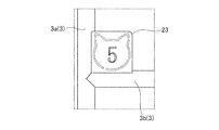
- FIG. 8 is a diagram illustrating an example in which a part recognizing part is formed by punching out a symbol reminiscent of a character silhouette.
- the part identification display unit 23 is formed by punching out the outline of the silhouette of the character (in this example, “cat”), and the part number (in this example, “5” ]) Is displayed.
- the product material is not limited to plastic, and can be applied to wooden or paper products.
Landscapes
- Business, Economics & Management (AREA)
- Engineering & Computer Science (AREA)
- Entrepreneurship & Innovation (AREA)
- Physics & Mathematics (AREA)
- Educational Administration (AREA)
- Educational Technology (AREA)
- General Physics & Mathematics (AREA)
- Theoretical Computer Science (AREA)
- Toys (AREA)
Abstract
【課題】組立作業に面白みを付加することができる模型キットおよび模型キットパッケージを提供する。 【解決手段】模型部品アセンブリ板から模型部品を取って模型を組立完成させる模型キットにおいて、模型部品を識別する部品識別表示部1aに、キャラクタのシルエットを想起させる図柄5を部品番号と共に表示する。この場合、図柄5の概略を部品識別表示部1aに打ち抜いて形成することや、部品識別表示部1aの形状を図柄5の形状にすることで図柄5を部品識別表示部1aに表示する。
Description
本発明は、組立てを容易にした模型キットおよび模型キットパッケージに関するものである。
プラスチック等からなる模型部品を組立てることで、自動車やロボット等の模型を完成させるための模型キットが知られている。この模型部品は、一枚又は複数枚の模型部品アセンブリ板のランナーに支持されている。この模型部品アセンブリ板のランナーには、模型部品それぞれに対応する番号を付した部品識別表示部が模型部品の近傍に設けられている。
そして、模型を組立てる際には、付属の組立説明書(以下、組立図という)の記載に従って、部品識別表示部に付された番号から必要なものを見つけ出し、ニッパ等の工具を用いて模型部品アセンブリ板から切り取って行うようにしている。
そして、模型を組立てる際には、付属の組立説明書(以下、組立図という)の記載に従って、部品識別表示部に付された番号から必要なものを見つけ出し、ニッパ等の工具を用いて模型部品アセンブリ板から切り取って行うようにしている。
ところで、模型も複雑なものになると、多数の模型部品を用いるのが一般的であり、1つの模型キットに多数の模型部品アセンブリ板が同梱されている場合もある。さらに、ロボット等の模型であると、左右の腕部のように同様な形状の模型部品が複数存在する場合があり、左右間違いなく組立てるためには、組立図に記載されている模型部品の番号と、部品識別表示部に付された番号とを、その都度見比べながら、手際よく順序だてて組立てることが要求されることとなる。
ここで、従来の模型部品アセンブリ板について、図9を参照して説明する。
図9(a)は、模型部品アセンブリ板の概観図であり、図9(b)は、この概観図の一部を拡大した図である。
図9(a)に示すように、模型部品アセンブリ板101は、当該模型部品アセンブリ板101の枠組みであるランナー103を介して、複数の模型部品105が一体成型されたものである。
図9(a)は、模型部品アセンブリ板の概観図であり、図9(b)は、この概観図の一部を拡大した図である。
図9(a)に示すように、模型部品アセンブリ板101は、当該模型部品アセンブリ板101の枠組みであるランナー103を介して、複数の模型部品105が一体成型されたものである。
各模型部品105の近傍には、図9(b)に示すように、部品識別表示部107が設けられている。この部品識別表示部107には、模型部品105それぞれの部品番号が表示されている。なお、各模型部品105は、ランナー103と一体に接続しているゲート部109をニッパ等で切断することで模型部品アセンブリ板101から切り離される。
しかしながら、模型を組立てる際に、組立図に記載されている模型部品の番号と、部品識別表示部に付された部品番号とを見比べて確認する作業が繰り返されるため、組立作業が単調となり、面白みに欠けるという問題がある。
また、模型部品アセンブリ板には、多数の模型部品が支持されているので、部品識別表示部に付された部品番号だけを手がかりに、必要とする模型部品を見つけ出すのに時間がかかるという問題がある。
さらに、模型部品アセンブリ板から1個ずつ取った模型部品が模型のどの位置に組立てられるのかを、その都度組立図を参照して、確認して組立てる必要があり、手間がかかるという問題がある。
また、模型部品アセンブリ板には、多数の模型部品が支持されているので、部品識別表示部に付された部品番号だけを手がかりに、必要とする模型部品を見つけ出すのに時間がかかるという問題がある。
さらに、模型部品アセンブリ板から1個ずつ取った模型部品が模型のどの位置に組立てられるのかを、その都度組立図を参照して、確認して組立てる必要があり、手間がかかるという問題がある。
そこで、本発明は、上記問題点に解決するために、組立作業に面白みを付加することができる模型キットおよび模型キットパッケージを提供するものである。
さらに他の目的は、手間や時間をかけることなく容易に組立てることができる模型キットおよび模型キットパッケージを提供するものである。
さらに他の目的は、手間や時間をかけることなく容易に組立てることができる模型キットおよび模型キットパッケージを提供するものである。
本発明の模型キットは、模型部品アセンブリ板から模型部品を取って模型を組立完成させる模型キットにおいて、模型部品アセンブリ板に設けられた模型部品を識別する部品識別表示部に、絵柄又は図柄が表示されている。
更に本発明の模型キットは、絵柄又は図柄の概略を部品識別表示部に打ち抜いて形成することが好ましい。
また、本発明の模型キットは、部品識別表示部の形状を、絵柄又は図柄の形状とすることが好ましい。
そして、本発明の模型キットは部品識別表示部に、模型部品の番号を表示することが好ましい。
また、本発明の模型キットは部品識別表示部に、模型部品アセンブリ板の構成素材を表示することが好ましい。
また、本発明の模型キットは、絵柄又は図柄は、キャラクタのシルエットを想起させる絵柄又は図柄であることが好ましい。
また、本発明の模型キットは、絵柄又は図柄は、模型部品を組立てた際の形状を予想させる絵柄又は図柄であることが好ましい。
また、本発明の模型キットパッケージは、模型キットが2つ以上同梱された模型キットパッケージであって、絵柄又は図柄は、その模型部品アセンブリ板の模型部品により組立完成される模型を識別可能にする絵柄又は図柄である。
本発明によれば、組立作業に面白みを付加することができる模型キットおよび模型キットパッケージを提供することができる。また、本発明によれば手間や時間をかけることなく容易に組立てることができる模型キットおよび模型キットパッケージを提供することができる。
模型部品アセンブリ板において、各模型部品の近傍に設けられた部品識別表示部に部品番号以外の図柄を表示した。
図1は、各模型部品の近傍に設けられた部品識別表示部を拡大して示した図である。図1(a)は従来の部品識別表示部107を示しており、図1(b)と(c)とが本発明の実施例を示した図である。
図1(b)に示すように、部品識別表示部1は、ランナー3の枝部3aと枝部3bとが交差する交差点を1つの頂点となす略四角形の形状に形成されている。 そして、この部品識別表示部1の縦横の大きさは、部品番号が小さくなりすぎて見えなくなることを防止するために、従来の部品識別表示部107よりも若干大きく形成されている。例えば、従来の部品識別表示部107が4.0mm×4.0mmであるのに対し、本発明の部品識別表示部1は6.0mm×6.0mmである。
この部品識別表示部1には、絵柄又は図柄(以下、図柄と統一して記載する)が表示されている。この実施例では、キャラクタのシルエットを想起させる図柄5が表示されている。このキャラクタには、模型部品を組立てた完成品(図示せず)とは、無関係のものを採用している。この実施例では、完成品が「ロボット」(図示せず)であり、キャラクタは「猫」である。
この実施例では、部品識別表示部1に表示されている図柄5は、キャラクタのシルエットを想起させるものであるが、図柄は、後記する「模型部品を組立てた際の形状を予想させる図柄」、「複数のプラモデルを区別可能にする図柄」であってもよい。
また、図1(c)に示すように、部品識別表示部1aには、キャラクタのシルエットを想起させる図柄5と共に部品番号(この例では「5」)が表示されている。
また、この図柄5は、模型部品アセンブリ板を成型する際に、当該アセンブリ板の金型に予め彫りこまれることによって形成された(周囲が削り取られることによって形成された)ものであり、部品識別表示部1が平面に形成されているのに対し、部品番号と共に凸部(又は凹部)として形成されている。そして、図1(c)に示したように、部品識別表示部1aは、キャラクタのシルエットの中に、部品番号が納まるように形成されている。
このように、部品識別表示部1、1aを構成することで、多数の模型部品アセンブリ板があり、模型部品を切り取る作業が何回も繰り返し行われたとしても、模型を組立てる製作者は、キャラクタのシルエットを目にすることで、単調な組立作業から一時でも開放され、模型の組立作業に面白みを持って取り組むことができる。
図2は、組立て完成される模型がロボットの模型である場合に、各模型部品の近傍に設けられた部品識別表示部を拡大して示した図である。図2に示すように、部品識別表示部7は、ランナー3の枝部3aと枝部3bとが交差する交差点を1つの頂点となす略四角形の形状に形成されている。
図2(a)に示すように、部品識別表示部7a(7)は、ロボットの腕部を模した図柄9a(9)を部品番号(この例では「6」)と共に表示したものである。また、図2(b)に示すように、部品識別表示部7b(7)は、ロボットの頭部を模した図柄9b(9)を部品番号(この例では「7」)と共に表示したものである。図2(c)に示すように、部品識別表示部7c(7)は、ロボットの脚部を模した図柄9c(9)を部品番号(この例では「8」)と共に表示したものである。この実施例では図柄9と共に部品番号を表示しているが、図柄9のみを表示してもよい。
また、この部品識別表示部7において、模型部品(図示せず)が、ロボットのどの部分であるかがわかるように、該当部分を強調して表示している。部品識別表示部7aの場合、模型部品がロボットの腕部の前腕αに該当することが明確になり、部品識別表示部7bの場合、模型部品がロボットの頭部のアンテナβに該当することが明確になり、部品識別表示部7cの場合、模型部品がロボットの脚部の大腿γに該当することが明確になっている。
さらに、組立て完成される模型がロボットの模型であるため、左右の腕部と、左右の脚部とがあり、間違って組立ててしまうことを防止するために、部品識別表示部7においては、左側の腕部と脚部とに「L」と、右側の腕部と脚部とに「R」とそれぞれ表示するように形成されている。
このように、部品識別表示部7には、模型部品(図示せず)を組立てた際の形状を予想させる図柄9を部品番号(この例では「6」「7」「8」)と共に表示している。つまり、部品識別表示部7aに表示されている番号「6」の模型部品は、ロボットの腕部の一部品であることが容易に予想でき、部品識別表示部7bに表示されている番号「7」の模型部品は、ロボットの顔部の一部品であることが容易に予想でき、部品識別表示部7cに表示されている番号「8」の模型部品は、ロボットの脚部の一部品であることが容易に予想できる。
そして、模型部品を組立てた際の形状を予想させる図柄9は、模型部品アセンブリ板を成型する際に、当該アセンブリ板の金型に予め彫りこまれることによって形成された(周囲が削り取られることによって形成された)ものであり、部品識別表示部7が平面に形成されているのに対し、部品番号と共に凸部(又は凹部)として形成されている。前記した強調して表示する前腕α、アンテナβ、大腿γが凸部の場合は、金型に彫りこむ溝幅を広くすることで形成できる。凹部の場合は、金型から削り取る部分を少なくすることで形成できる。
なお、この図2では、部品識別表示部7を構成する四角形の隅に、部品番号を表示しているが、図柄9の中に、部品番号が納まるように表示しても、或いは、四角形の略中央に表示してもよい。
このように、部品識別表示部7を構成することで、多数の模型部品アセンブリ板があった場合に、各模型部品アセンブリ板から切り取った模型部品を組立てた際の形状を予想することができ、切り取って組立てる際にその都度組立図を確認しなくてもいいので、模型を容易に組立てることができる。
図3は、2つ以上の模型キットが同梱された模型キットパッケージにおける模型部品アセンブリ板において、各模型部品の近傍に設けられた部品識別表示部を拡大して示した図である。図3に示すように、部品識別表示部11は、ランナー3の枝部3aと枝部3bとが交差する交差点を1つの頂点となす略四角形の形状に形成されている。
この実施例3は、3個の模型(戦車、戦闘機、潜水艦)が組み立てられる3種の模型キットが、一つの模型キットパッケージ(例えば、近代兵器セット)に同梱されている場合に、部品識別表示部11に、その模型部品アセンブリ板の模型部品から組み立てられる模型を識別可能にする図柄13を表示したものである。
すなわち、図3(a)に示すように、部品識別表示部11a(11)は、戦車の模型を示す図柄13a(13)を部品番号(この例では「9」)と共に表示している。また、図3(b)に示すように、部品識別表示部11b(11)は、戦闘機の模型を示す図柄13b(13)を部品番号(この例では「10」)と共に表示している。さらに、図3(c)に示すように、部品識別表示部11c(11)に潜水艦の模型を示す図柄13c(13)を部品番号(この例では「11」)と共に表示している。なお、この実施例では、図柄13と共に部品番号を表示しているが、図柄13のみを表示してもよい。
このように、部品識別表示部11を構成することで、一つのパッケージに複数の模型キットが同梱されている場合でも、各模型部品がどの模型の部品であるかが、当該模型部品を切り取る際に確認することができるので、模型部品を切り取るたびに組立図を確認する必要が無くなり、手間をかけることなく、容易に模型を組立てることができる。
図4は、部品識別表示部の形状を、図1に示したキャラクタのシルエットの形状にした例を示す図である。
この図4に示すように、部品識別表示部15は、キャラクタのシルエットの形状に形成されており、部品番号(この例では「5」)が略中央に表示されている。
この図4に示すように、部品識別表示部15は、キャラクタのシルエットの形状に形成されており、部品番号(この例では「5」)が略中央に表示されている。
このように、部品識別表示部15を構成することで、模型を組立てる製作者は、キャラクタのシルエットを目にすることで、単調な組立作業から一時でも開放され、模型の組立作業に面白みを持って取り組むことができる。
図5は、部品識別表示部の形状を、図2に示した、組立てた際の形状を予想させる形状にした例を示す図である。
この図5(a)に示すように、部品識別表示部17a(17)は、ロボットの腕部の形状に形成されており、部品番号(この例では「6」)が前腕部分に表示されている。また、図5(b)に示すように、部品識別表示部17b(17)は、ロボットの頭部の形状に形成されており、部品番号(この例では「7」)がロボットの額部分に表示されている。さらに、図5(c)に示すように、部品識別表示部17cは、ロボットの脚部の形状に形成されており、部品番号(この例では「8」)がロボットの下肢部分に表示されている。
この図5(a)に示すように、部品識別表示部17a(17)は、ロボットの腕部の形状に形成されており、部品番号(この例では「6」)が前腕部分に表示されている。また、図5(b)に示すように、部品識別表示部17b(17)は、ロボットの頭部の形状に形成されており、部品番号(この例では「7」)がロボットの額部分に表示されている。さらに、図5(c)に示すように、部品識別表示部17cは、ロボットの脚部の形状に形成されており、部品番号(この例では「8」)がロボットの下肢部分に表示されている。
このように、部品識別表示部17を構成することで、各模型部品アセンブリ板から切り取った模型部品を組立てた際の形状を予想することができ、切り取って組立てる際にその都度組立図を確認しなくてもいいので、模型を容易に組立てることができる。
図6は、部品識別表示部の形状を、図3に示した複数の模型の形状にした例を示す図である。
この図6(a)に示すように、部品識別表示部19a(19)は、戦車の形状に形成されており、部品番号(この例では「9」)が略中央に表示されている。また、図6(b)に示すように、部品識別表示部19b(19)は、戦闘機の形状に形成されており、部品番号(この例では「10」)が略中央に表示されている。さらに、図6(c)に示すように、部品識別表示部19c(19)は、潜水艦の形状に形成されており、部品番号(この例では「11」)が略中央に表示されている。
この図6(a)に示すように、部品識別表示部19a(19)は、戦車の形状に形成されており、部品番号(この例では「9」)が略中央に表示されている。また、図6(b)に示すように、部品識別表示部19b(19)は、戦闘機の形状に形成されており、部品番号(この例では「10」)が略中央に表示されている。さらに、図6(c)に示すように、部品識別表示部19c(19)は、潜水艦の形状に形成されており、部品番号(この例では「11」)が略中央に表示されている。
このように、部品識別表示部19を構成することで、一つのパッケージに複数の模型キットが同梱されている場合でも、各模型部品がどの模型の部品であるかが、当該模型部品を切り取る際に確認することができるので、模型部品を切り取るたびに組立図を確認する必要が無くなり、手間をかけることなく、容易に模型を組立てることができる。
図7は、部品識別表示部に模型部品アセンブリ板の製品素材を示した図である。この図7に示したように、部品識別表示部21には、部品番号と共に製品素材(構成素材)を示す「PS」(ポリスチレン)が表示されている。なお、その他の製品材料として、「PE」(ポリエチレン)、「PP」(ポリプロピレン)等が挙げられる。
このように、部品識別表示部21を構成することで、製品素材ごとの分別廃棄が容易に行うことができる。特に、模型部品を模型部品アセンブリ板から切り取った際に、模型部品に微小なゲート部が結合している場合に、模型製作者は、切り取る直前に確認した部品識別表示部21に製品素材が表示されているので、切り取った直後、この微小なゲート部を意識して分別廃棄することができる。
なお、この図7では、図示していないが、この製品素材の表示を、図1から図6に示した部品識別表示部や後記する図8の部品識別表示部23に適用してもよい。
図8は、部品識別表示部にキャラクタのシルエットを想起する図柄を打ち抜いて形成した例を示す図である。
この図8に示したように、部品識別表示部23は、キャラクタ(この例では「猫」)のシルエットの概略が打ち抜いて形成されており、このシルエットの中央に部品番号(この例では「5」)が表示されている。
この図8に示したように、部品識別表示部23は、キャラクタ(この例では「猫」)のシルエットの概略が打ち抜いて形成されており、このシルエットの中央に部品番号(この例では「5」)が表示されている。
このように、部品識別表示部23を構成することで、模型を組立てる製作者は、キャラクタのシルエットを目にすることで、単調な組立作業から一時でも開放され、模型の組立作業に面白みを持って取り組むことができる。
模型部品の番号を表示する部品識別表示部(番号プレート)がある模型であれば、製品素材はプラスチックに限定されず、木製のものや紙製のものに適用することができる。
1、1a、7、11、15、17、19、21、23 部品識別表示部
3 ランナー
5、9、13 図柄
3 ランナー
5、9、13 図柄
Claims (8)
- 模型部品アセンブリ板から模型部品を取って模型を組立完成させる模型キットにおいて、
模型部品アセンブリ板に設けられた模型部品を識別する部品識別表示部に、絵柄又は図柄を表示する模型キット。 - 前記絵柄又は図柄の概略を前記部品識別表示部に打ち抜いて形成する請求項1に記載の模型キット。
- 前記部品識別表示部の形状を、前記絵柄又は図柄の形状にする請求項1又は請求項2に記載の模型キット。
- 前記部品識別表示部に、前記模型部品の番号を表示する請求項1乃至3のいずれかに記載の模型キット。
- 前記部品識別表示部に、前記模型部品アセンブリ板の構成素材を表示する請求項1乃至4のいずれかに記載の模型キット。
- 前記絵柄又は図柄は、キャラクタのシルエットを想起させる絵柄又は図柄である請求項1乃至5に記載の模型キット。
- 前記絵柄又は図柄は、前記模型部品を組立てた際の形状を予想させる絵柄又は図柄である請求項1乃至5のいずれかに記載の模型キット。
- 請求項1乃至5のいずれかに記載の模型キットが2つ以上同梱された模型キットパッケージであって、
前記絵柄又は図柄は、その模型部品アセンブリ板の模型部品により組立完成される模型を識別可能にする絵柄又は図柄である模型キットパッケージ。
Applications Claiming Priority (2)
| Application Number | Priority Date | Filing Date | Title |
|---|---|---|---|
| JP2009-004962U | 2009-07-16 | ||
| JP2009004962U JP3154497U (ja) | 2009-07-16 | 2009-07-16 | 模型キットおよび模型キットパッケージ |
Publications (1)
| Publication Number | Publication Date |
|---|---|
| WO2011007626A1 true WO2011007626A1 (ja) | 2011-01-20 |
Family
ID=43449235
Family Applications (1)
| Application Number | Title | Priority Date | Filing Date |
|---|---|---|---|
| PCT/JP2010/059451 Ceased WO2011007626A1 (ja) | 2009-07-16 | 2010-06-03 | 模型キットおよび模型キットパッケージ |
Country Status (2)
| Country | Link |
|---|---|
| JP (1) | JP3154497U (ja) |
| WO (1) | WO2011007626A1 (ja) |
Cited By (3)
| Publication number | Priority date | Publication date | Assignee | Title |
|---|---|---|---|---|
| CN111231239A (zh) * | 2019-02-05 | 2020-06-05 | 株式会社万代 | 模型部件 |
| JP2021069948A (ja) * | 2021-01-04 | 2021-05-06 | 株式会社バンダイ | 模型部品 |
| EP3908350A1 (en) * | 2019-01-09 | 2021-11-17 | SHL Medical AG | Bulk handling feature |
Families Citing this family (10)
| Publication number | Priority date | Publication date | Assignee | Title |
|---|---|---|---|---|
| JP4979799B2 (ja) * | 2010-09-15 | 2012-07-18 | 株式会社バンダイ | パーツ供給品 |
| JP4927204B2 (ja) * | 2010-09-15 | 2012-05-09 | 株式会社バンダイ | パーツ供給品 |
| JP5753111B2 (ja) * | 2012-02-07 | 2015-07-22 | 株式会社バンダイ | パーツ供給品 |
| JP5753122B2 (ja) * | 2012-04-16 | 2015-07-22 | 株式会社バンダイ | パーツ供給品 |
| JP5855304B1 (ja) * | 2015-04-23 | 2016-02-09 | 株式会社バンダイ | プラスチックモデルキット |
| JP2019202075A (ja) * | 2018-05-25 | 2019-11-28 | 株式会社プレックス | 組み立て式玩具、及び、組み立て式玩具の成形物の製造方法 |
| CN109949689A (zh) * | 2019-05-08 | 2019-06-28 | 武汉普道蓝图创意工程股份有限公司 | 一种机器人剖析展示平台 |
| JP7083057B1 (ja) * | 2021-04-14 | 2022-06-09 | 株式会社バンダイ | パーツ供給体 |
| JP7720460B1 (ja) | 2024-08-09 | 2025-08-07 | 株式会社バンダイ | 組立玩具及び組立部品 |
| JP7796927B1 (ja) * | 2025-04-28 | 2026-01-09 | 株式会社バンダイ | 模型素体、模型部品、及び模型素体の製造方法 |
Citations (3)
| Publication number | Priority date | Publication date | Assignee | Title |
|---|---|---|---|---|
| JP2002370257A (ja) * | 2001-06-15 | 2002-12-24 | Kasai Kogyo Co Ltd | 樹脂スクラップの回収方法 |
| JP2009107275A (ja) * | 2007-10-31 | 2009-05-21 | Bandai Co Ltd | パーツ供給品及び模型 |
| JP4291396B1 (ja) * | 2008-06-16 | 2009-07-08 | 株式会社バンダイ | 模型用樹脂成形部品 |
-
2009
- 2009-07-16 JP JP2009004962U patent/JP3154497U/ja not_active Expired - Lifetime
-
2010
- 2010-06-03 WO PCT/JP2010/059451 patent/WO2011007626A1/ja not_active Ceased
Patent Citations (3)
| Publication number | Priority date | Publication date | Assignee | Title |
|---|---|---|---|---|
| JP2002370257A (ja) * | 2001-06-15 | 2002-12-24 | Kasai Kogyo Co Ltd | 樹脂スクラップの回収方法 |
| JP2009107275A (ja) * | 2007-10-31 | 2009-05-21 | Bandai Co Ltd | パーツ供給品及び模型 |
| JP4291396B1 (ja) * | 2008-06-16 | 2009-07-08 | 株式会社バンダイ | 模型用樹脂成形部品 |
Cited By (10)
| Publication number | Priority date | Publication date | Assignee | Title |
|---|---|---|---|---|
| EP3908350A1 (en) * | 2019-01-09 | 2021-11-17 | SHL Medical AG | Bulk handling feature |
| US20220062562A1 (en) * | 2019-01-09 | 2022-03-03 | Shl Medical Ag | Bulk handling feature |
| CN111231239A (zh) * | 2019-02-05 | 2020-06-05 | 株式会社万代 | 模型部件 |
| WO2020162082A1 (ja) * | 2019-02-05 | 2020-08-13 | 株式会社バンダイ | 模型部品 |
| JP2020124395A (ja) * | 2019-02-05 | 2020-08-20 | 株式会社バンダイ | 模型部品 |
| JP7000367B2 (ja) | 2019-02-05 | 2022-01-19 | 株式会社バンダイ | 模型部品 |
| CN111231239B (zh) * | 2019-02-05 | 2022-07-26 | 株式会社万代 | 模型部件 |
| CN115401876A (zh) * | 2019-02-05 | 2022-11-29 | 株式会社万代 | 模型部件 |
| JP2021069948A (ja) * | 2021-01-04 | 2021-05-06 | 株式会社バンダイ | 模型部品 |
| JP2023168374A (ja) * | 2021-01-04 | 2023-11-24 | 株式会社バンダイ | 模型部品 |
Also Published As
| Publication number | Publication date |
|---|---|
| JP3154497U (ja) | 2009-10-22 |
Similar Documents
| Publication | Publication Date | Title |
|---|---|---|
| JP3154497U (ja) | 模型キットおよび模型キットパッケージ | |
| JP4541016B2 (ja) | 繊細な図記号が装備された操作ボタン、装飾パネルおよびインストルメントパネルの製造方法 | |
| JP4291396B1 (ja) | 模型用樹脂成形部品 | |
| WO2011000506A3 (en) | Simulation of a process | |
| WO2018139063A1 (ja) | 3dプリンタ用の冶具及び当該治具を備えた3dプリンタ | |
| EP1770467A1 (en) | Design and fabrication of molds using a client-server architecture | |
| JP4575475B2 (ja) | 二色成形金型 | |
| CN103934358B (zh) | 一种数控冲床用椭圆孔冲裁模具及椭圆孔冲裁方法 | |
| JP6347541B2 (ja) | フロアパネルの塞ぎ板 | |
| KR102024146B1 (ko) | 다양한 접착면에 접착제 보호용 이형지가 부착되고 자동화가 가능한 원단제품의 제작공정 및 이를 이용하여 제작한 원단제품 | |
| KR101314244B1 (ko) | 자동 부착용 라벨 및 이의 제조 방법 | |
| CN109054675A (zh) | 一种电子设备膜及其制备方法 | |
| JP2015134483A (ja) | 三次元造形物の張出構造および三次元造形物の製造方法 | |
| JP5878108B2 (ja) | コンソール用ドアの表皮成形方法 | |
| CN102902835A (zh) | 一种冷冲压模具凹模套设计模板 | |
| JP3151604U (ja) | 成形装置、及び成形物 | |
| JP5967733B1 (ja) | 成形金型 | |
| JP3151526U (ja) | 模型用部品提供体 | |
| JP3106540U (ja) | 彫刻刀 | |
| RU2007123570A (ru) | Способ и оборудование, используемые для резания и моделирования листов кожи или других моделируемых материалов | |
| JP4767092B2 (ja) | 板金板取方法 | |
| JP5582763B2 (ja) | 打ち抜き機における面版装置 | |
| KR20140078565A (ko) | 가요성 휴대용 전자 디바이스의 제조 방법 | |
| JP6345990B2 (ja) | 加飾成形品、及び加飾成形品の製造方法 | |
| KR101314220B1 (ko) | 모바일기기용 투광성 커버심재의 제조방법 및 그 투광성 커버심재 |
Legal Events
| Date | Code | Title | Description |
|---|---|---|---|
| 121 | Ep: the epo has been informed by wipo that ep was designated in this application |
Ref document number: 10799688 Country of ref document: EP Kind code of ref document: A1 |
|
| NENP | Non-entry into the national phase |
Ref country code: DE |
|
| 122 | Ep: pct application non-entry in european phase |
Ref document number: 10799688 Country of ref document: EP Kind code of ref document: A1 |