WO2011007600A1 - ゲーム装置及びコンピュータプログラム - Google Patents
ゲーム装置及びコンピュータプログラム Download PDFInfo
- Publication number
- WO2011007600A1 WO2011007600A1 PCT/JP2010/053998 JP2010053998W WO2011007600A1 WO 2011007600 A1 WO2011007600 A1 WO 2011007600A1 JP 2010053998 W JP2010053998 W JP 2010053998W WO 2011007600 A1 WO2011007600 A1 WO 2011007600A1
- Authority
- WO
- WIPO (PCT)
- Prior art keywords
- value
- load
- data
- support portion
- computer program
- Prior art date
- Legal status (The legal status is an assumption and is not a legal conclusion. Google has not performed a legal analysis and makes no representation as to the accuracy of the status listed.)
- Ceased
Links
Images


Classifications
-
- A—HUMAN NECESSITIES
- A63—SPORTS; GAMES; AMUSEMENTS
- A63F—CARD, BOARD, OR ROULETTE GAMES; INDOOR GAMES USING SMALL MOVING PLAYING BODIES; VIDEO GAMES; GAMES NOT OTHERWISE PROVIDED FOR
- A63F13/00—Video games, i.e. games using an electronically generated display having two or more dimensions
- A63F13/20—Input arrangements for video game devices
- A63F13/21—Input arrangements for video game devices characterised by their sensors, purposes or types
- A63F13/214—Input arrangements for video game devices characterised by their sensors, purposes or types for locating contacts on a surface, e.g. floor mats or touch pads
-
- A—HUMAN NECESSITIES
- A63—SPORTS; GAMES; AMUSEMENTS
- A63F—CARD, BOARD, OR ROULETTE GAMES; INDOOR GAMES USING SMALL MOVING PLAYING BODIES; VIDEO GAMES; GAMES NOT OTHERWISE PROVIDED FOR
- A63F13/00—Video games, i.e. games using an electronically generated display having two or more dimensions
- A63F13/20—Input arrangements for video game devices
- A63F13/21—Input arrangements for video game devices characterised by their sensors, purposes or types
- A63F13/218—Input arrangements for video game devices characterised by their sensors, purposes or types using pressure sensors, e.g. generating a signal proportional to the pressure applied by the player
-
- A—HUMAN NECESSITIES
- A63—SPORTS; GAMES; AMUSEMENTS
- A63F—CARD, BOARD, OR ROULETTE GAMES; INDOOR GAMES USING SMALL MOVING PLAYING BODIES; VIDEO GAMES; GAMES NOT OTHERWISE PROVIDED FOR
- A63F13/00—Video games, i.e. games using an electronically generated display having two or more dimensions
- A63F13/40—Processing input control signals of video game devices, e.g. signals generated by the player or derived from the environment
- A63F13/42—Processing input control signals of video game devices, e.g. signals generated by the player or derived from the environment by mapping the input signals into game commands, e.g. mapping the displacement of a stylus on a touch screen to the steering angle of a virtual vehicle
-
- G—PHYSICS
- G06—COMPUTING OR CALCULATING; COUNTING
- G06F—ELECTRIC DIGITAL DATA PROCESSING
- G06F3/00—Input arrangements for transferring data to be processed into a form capable of being handled by the computer; Output arrangements for transferring data from processing unit to output unit, e.g. interface arrangements
- G06F3/01—Input arrangements or combined input and output arrangements for interaction between user and computer
- G06F3/03—Arrangements for converting the position or the displacement of a member into a coded form
- G06F3/033—Pointing devices displaced or positioned by the user, e.g. mice, trackballs, pens or joysticks; Accessories therefor
- G06F3/0334—Foot operated pointing devices
-
- A—HUMAN NECESSITIES
- A63—SPORTS; GAMES; AMUSEMENTS
- A63F—CARD, BOARD, OR ROULETTE GAMES; INDOOR GAMES USING SMALL MOVING PLAYING BODIES; VIDEO GAMES; GAMES NOT OTHERWISE PROVIDED FOR
- A63F13/00—Video games, i.e. games using an electronically generated display having two or more dimensions
- A63F13/50—Controlling the output signals based on the game progress
- A63F13/53—Controlling the output signals based on the game progress involving additional visual information provided to the game scene, e.g. by overlay to simulate a head-up display [HUD] or displaying a laser sight in a shooting game
- A63F13/533—Controlling the output signals based on the game progress involving additional visual information provided to the game scene, e.g. by overlay to simulate a head-up display [HUD] or displaying a laser sight in a shooting game for prompting the player, e.g. by displaying a game menu
-
- A—HUMAN NECESSITIES
- A63—SPORTS; GAMES; AMUSEMENTS
- A63F—CARD, BOARD, OR ROULETTE GAMES; INDOOR GAMES USING SMALL MOVING PLAYING BODIES; VIDEO GAMES; GAMES NOT OTHERWISE PROVIDED FOR
- A63F13/00—Video games, i.e. games using an electronically generated display having two or more dimensions
- A63F13/80—Special adaptations for executing a specific game genre or game mode
- A63F13/803—Driving vehicles or craft, e.g. cars, airplanes, ships, robots or tanks
-
- A—HUMAN NECESSITIES
- A63—SPORTS; GAMES; AMUSEMENTS
- A63F—CARD, BOARD, OR ROULETTE GAMES; INDOOR GAMES USING SMALL MOVING PLAYING BODIES; VIDEO GAMES; GAMES NOT OTHERWISE PROVIDED FOR
- A63F2300/00—Features of games using an electronically generated display having two or more dimensions, e.g. on a television screen, showing representations related to the game
- A63F2300/10—Features of games using an electronically generated display having two or more dimensions, e.g. on a television screen, showing representations related to the game characterized by input arrangements for converting player-generated signals into game device control signals
- A63F2300/1056—Features of games using an electronically generated display having two or more dimensions, e.g. on a television screen, showing representations related to the game characterized by input arrangements for converting player-generated signals into game device control signals involving pressure sensitive buttons
-
- A—HUMAN NECESSITIES
- A63—SPORTS; GAMES; AMUSEMENTS
- A63F—CARD, BOARD, OR ROULETTE GAMES; INDOOR GAMES USING SMALL MOVING PLAYING BODIES; VIDEO GAMES; GAMES NOT OTHERWISE PROVIDED FOR
- A63F2300/00—Features of games using an electronically generated display having two or more dimensions, e.g. on a television screen, showing representations related to the game
- A63F2300/60—Methods for processing data by generating or executing the game program
- A63F2300/6045—Methods for processing data by generating or executing the game program for mapping control signals received from the input arrangement into game commands
-
- A—HUMAN NECESSITIES
- A63—SPORTS; GAMES; AMUSEMENTS
- A63F—CARD, BOARD, OR ROULETTE GAMES; INDOOR GAMES USING SMALL MOVING PLAYING BODIES; VIDEO GAMES; GAMES NOT OTHERWISE PROVIDED FOR
- A63F2300/00—Features of games using an electronically generated display having two or more dimensions, e.g. on a television screen, showing representations related to the game
- A63F2300/80—Features of games using an electronically generated display having two or more dimensions, e.g. on a television screen, showing representations related to the game specially adapted for executing a specific type of game
- A63F2300/8017—Driving on land or water; Flying
Definitions
- the present invention relates to a game device and a computer program, and more particularly to a game device and a computer program using a controller.
- Patent Document 1 a technique has been proposed in which a player rides on a controller provided with a plurality of load sensors, and the player performs a game input operation by changing how the load is applied on the controller.
- An object of the present invention is to provide a game device and a computer program capable of realizing a realistic operation.
- a support portion that supports a player, a first load sensor that is provided at a right front portion of the support portion and detects a load from the support portion, and a right rear portion of the support portion.
- a second load sensor that detects a load from the support portion; a third load sensor that is provided at a left front portion of the support portion and detects a load from the support portion; and a left of the support portion.
- a computer program for causing a computer to function as a game device using a controller provided at a rear portion and having a fourth load sensor for detecting a load from the support portion, wherein the computer is connected to the first load.
- a first value is calculated based on the difference between the first load data based on the output of the sensor and the second load data based on the output of the second load sensor, and based on the output of the third load sensor.
- Z A second value is calculated based on the difference between the third load data and the fourth load data based on the output of the fourth load sensor, and based on the first value and the second value.
- a support portion that supports a player, a first load sensor that is provided at a right front portion of the support portion and detects a load from the support portion, and A second load sensor for detecting a load from the support portion provided at a right rear portion; a third load sensor for detecting a load from the support portion provided at a left front portion of the support portion; A first load data based on an output of the first load sensor, wherein the first load data is based on an output of the first load sensor; and a fourth load sensor for detecting a load from the support portion.
- the first load data based on the output of the first load sensor provided at the right front portion of the support portion where the player is supported, and the output of the second load sensor provided at the right rear portion of the support portion. Based on the difference from the second load data based on the first value, the first value is calculated. Further, based on the difference between the third load data based on the output of the third load sensor provided on the left front portion of the support portion and the fourth load data based on the output of the fourth load sensor on the left rear portion, A second value is calculated. Then, the behavior of the object displayed on the display screen is determined based on the first value and the second value. Therefore, according to the present invention, it is also possible to turn an object and the like, and it is possible to enjoy a realistic game.
- FIG. 1 is an external view of a game device according to an embodiment of the present invention.
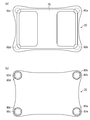
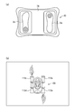
- FIG. 2 is a top view and a bottom view showing a controller used in an embodiment of the present invention.
- FIG. 3 is a block diagram showing a game device according to an embodiment of the present invention.
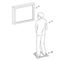
- FIG. 4 is a perspective view showing a state where the player is riding on the first controller.
- FIG. 5 is a diagram showing an example of a display screen of the game device according to the embodiment of the present invention.
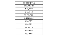
- FIG. 6 is a diagram showing each memory provided in the system memory.
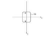
- FIG. 7 is a diagram illustrating the relationship between the local coordinate system and the object.
- FIG. 8 is a flowchart showing processing for determining the behavior of an object.
- FIG. 1 is an external view of a game device according to an embodiment of the present invention.
- FIG. 2 is a top view and a bottom view showing a controller used in an embodiment of the present invention.
- FIG. 3 is a block diagram showing a game
- FIG. 9 is a diagram illustrating an operation of the first controller by the player's foot.
- FIG. 10 is a diagram illustrating a case where the player adds weight to the toe side of the right foot and the toe side of the left foot.
- FIG. 11 is a diagram illustrating a case where the player adds weight to the heel side of the right foot and the heel side of the left foot.
- FIG. 12 is a diagram illustrating a case where the player puts weight on the heel side of the right foot and the toe side of the left foot.
- FIG. 13 is a diagram illustrating a case where the player puts weight on the heel side of the left foot and the toe side of the right foot.
- FIG. 14 is a diagram illustrating a specific example (part 1) of the behavior of the object.
- FIG. 14 is a diagram illustrating a specific example (part 1) of the behavior of the object.
- FIG. 15 is a diagram illustrating a specific example (part 2) of the behavior of the object.
- FIG. 16 is a diagram illustrating a specific example (part 3) of the behavior of the object.
- FIG. 17 is a diagram illustrating a specific example (part 4) of the behavior of the object.
- FIG. 18 is a diagram illustrating a specific example (part 5) of the behavior of the object.
- FIG. 1 is an external view of the game apparatus according to the present embodiment.
- the game apparatus 10 of the present embodiment is used by being connected to a TV monitor (display unit, display means) 4 installed on the TV stand 2.
- the game apparatus 10 includes a game apparatus main body 12, a first controller 20 operated by a player (player), and a second controller 22 operated by the player.
- the game apparatus body 12 and the TV monitor 4 are connected by a cable.
- the game apparatus body 12 and the first controller 20 can communicate wirelessly. Further, the game apparatus body 12 and the second controller 22 can communicate wirelessly.
- FIG. 2 is a top view and a bottom view showing a controller used in the present embodiment.
- FIG. 2A is a top view
- FIG. 2B is a bottom view.
- the first controller 20 includes a support part 78 on which a player's foot is placed, and four load sensors 82 a provided at four corners of the support part 78 for detecting the load applied to the support part 20. To 82d.
- the controller 20 transmits the load detection values detected by the load sensors 82a to 82d to the game apparatus body 12. While the player is on the first controller 20, the player adjusts the weighting method to operate the behavior of the object displayed on the television monitor 4 to play the game.
- the second controller 22 is operated by the player's hand 23, for example.
- Various operation buttons 28 such as a power button 28 a and a cross button 28 b are provided on the operation surface of the second controller 22.
- the player can use the second controller 22 to input an instruction to start the game or the like to the game apparatus body 12.
- FIG. 3 is a block diagram showing the game apparatus according to the present embodiment.
- the game apparatus 10 stores a CPU 40 that executes game programs, controls the entire system, calculates coordinates for image display, and the like, and programs and data necessary for the CPU 40 to perform processing.
- a system memory (RAM) 42 used as a buffer memory is connected in common by a bus line and is connected to a bus arbiter 44.
- the bus arbiter 44 controls the flow of programs and data with each block of the game apparatus 10 and devices connected to the outside.
- a game data storage device or storage medium including an optical disk or optical disk drive for driving a game recording medium such as a CD-ROM) 46 in which a game program and data (including video data and music data) are stored;
- a BOOTROM 48 storing a program and data for starting the apparatus 10 is connected to the bus arbiter 44 through a bus line.
- polygon data (vertex data) having three-dimensional local coordinate data constituting an object to be displayed and NURBS (NonNUniform Rational B-Spline) data (surface and control) are generated in the system memory 42.
- Point data is stored, and this is arranged in the world coordinate system of the three-dimensional virtual space by the CPU 40 or geometry processor (not shown) to convert the local coordinates into the world coordinate system.
- viewpoint coordinates generated in accordance with the player's operation or the progress of the game are set in the world coordinate system, and the object in the field of view as viewed from the viewpoint in the predetermined viewing direction and angle of view is set to the viewpoint coordinates as the origin.
- the coordinates of the converted object are transmitted to the rendering processor 50.
- the rendering processor 50 first applies interpolation processing such as light source processing or texture data stored in the graphic memory 52 to the object to detail the surface of the object with respect to the coordinates of the object sent. Further, the rendering processor 50 projects an object (polygon) from a three-dimensional solid object onto a two-dimensional plane (screen) for display on the television monitor 4 and converts it into two-dimensional coordinate data (screen coordinate system). A two-dimensional image is generated so as to be displayed preferentially from a polygon having a shallow coordinate depth, that is, a polygon close to the viewpoint coordinate, and this is output to a television monitor 4 such as a CRT or a liquid crystal display device.
- interpolation processing such as light source processing or texture data stored in the graphic memory 52 to the object to detail the surface of the object with respect to the coordinates of the object sent. Further, the rendering processor 50 projects an object (polygon) from a three-dimensional solid object onto a two-dimensional plane (screen) for display on the television monitor 4 and converts it into two-dimensional coordinate data (
- a rendering processor 50 that reproduces video (MOVIE) data read from the program data storage device or the storage medium 46 via the bus arbiter 44 or generates an image for image display in accordance with the player's operation or game progress.
- a graphic memory 52 for storing graphic data necessary for the rendering processor 50 to generate an image.
- the image signal output from the rendering processor 50 is converted from a digital signal to an analog signal by the video DAC 54 and displayed on the television monitor 4.
- a sound processor 56 that reproduces music data read from the program data storage device or the storage medium 46 via the bus arbiter 44, and generates sound effects and sounds according to the operation by the player and the progress of the game, and the sound processor 56 is connected to a sound memory 58 for storing sound data and the like necessary for generating sound effects and sounds.
- the audio signal output from the sound processor 56 is converted from a digital signal to an analog signal by the audio DAC 60 and output from the speaker of the television monitor 4.
- a communication interface 62 is connected to the bus arbiter 44.
- the communication interface 62 is connected to an external network such as a telephone line via the LAN adapter 64.
- the game apparatus body 12 is connected to the Internet by a LAN adapter 64, and can communicate with other game apparatuses, network servers, and the like.
- the communication interface 62 and the LAN adapter 64 use a telephone line, but use a terminal adapter (TA) or router that uses a telephone line, a cable modem that uses a cable TV line, a mobile phone or a PHS.
- TA terminal adapter
- Other communication methods such as wireless communication means and optical fiber communication means using an optical fiber may be used.
- the bus arbiter 44 is connected to a wireless reception unit 68 for wireless communication with the controller 20 and the remote controller 22.
- the wireless reception unit 68 receives information transmitted from the first controller 20 and information transmitted from the second controller 22.
- a peripheral I / F (interface) 70 is connected to the bus arbiter 44.
- Various peripheral devices can be connected via the peripheral I / F 70.
- the game device 10 is not limited to a home game device, and is installed in a store such as a personal computer, a portable electronic game machine, an electronic device such as a mobile phone or a PDA, an amusement facility, a game cafe, or the like.
- An information processing device such as a game device may be used.
- controller Next, the first controller used in the present embodiment will be described with reference to FIGS.
- the first controller 20 functions as a game operation device (operation means).
- the controller 20 includes a support part (support plate) 78 for the player to get on, and load sensors 82a to 82d for detecting loads applied to the support part 78.
- the load sensors 82a to 82d are arranged at the four corners of the support portion 78.
- a first load sensor 82 a is disposed at the right front portion of the support portion 78, and a second load sensor 82 b is disposed at the right rear portion of the support portion 78.
- a third load sensor 82 c is disposed at the left front portion, and a fourth load sensor 82 d is disposed at the left rear portion of the support portion 78.
- Legs 80a to 80d are provided at the four corners of the first controller 20. Each leg 80a to 80d is formed in a columnar shape, for example.
- the first load sensor 82a is supported by the leg 80a
- the second load sensor 82b is supported by the leg 80b
- the third load sensor 82c is supported by the leg 80c
- 82d is supported by a leg 80d. That is, the support portion 78 is supported by the four legs 80a to 80d via the four load sensors 82a to 82d provided at the four corners.
- FIG. 4 is a perspective view showing a state where the player is riding on the first controller.
- load sensors 82a to 82d for example, strain gauge type load cells can be used.
- the load sensors 82a to 82d output an electrical signal having a magnitude corresponding to the applied load.
- the first controller 20 can appropriately use a controller having a plurality of load sensors that detect a load applied to the support portion.
- the first controller 20 has a CPU 88 that controls the operation of the entire first controller 20.
- the CPU 88 is connected to a ROM, RAM, etc. (not shown).
- the CPU 88 controls the operation of the first controller 20 by a computer program stored in the ROM.
- the load sensors 82a to 82d are connected to the AD converter 86 via amplifiers 84a to 84d, respectively.
- the wireless transmission unit 90 is for transmitting data from the first controller 20 to the game apparatus main body 12.
- the wireless transmission unit 90 is provided, for example, inside the first controller 20.
- a predetermined voltage is supplied to the load sensors 82a to 82d, the amplifiers 84a to 84d, the AD converter 86, the CPU 88, and the wireless transmission unit 90 by a battery (not shown) such as a battery.
- Each of the load sensors 82a to 82d outputs a signal indicating the input load.
- the electric signals output from the load sensors 82a to 82d are amplified by the amplifier 84, converted from analog signals to digital data by the AD converter 86, and input to the CPU 88.
- Identification information of each load sensor 82 to 82d is given to the data of the detection value by each load sensor 82a to 82d, and it becomes possible to identify which load sensor 82a to 82d is the load detection value.
- the CPU 88 acquires data f1 to f4 indicating load detection values by the load sensors 82a to 82d.
- f1 is data indicating a load detection value by the first load sensor 82a
- f2 is data indicating a load detection value by the second load sensor 82b
- f3 is a load detection value by the third load sensor 82c.
- F4 is data indicating a load detection value by the fourth load sensor 82d.
- the data f1 to f4 indicating the load detection values by the load sensors 82a to 82d are transmitted as operation input data of the first controller 20 from the CPU 88 to the game apparatus body 12 via the wireless transmission unit 90.
- the CPU 88 transmits data f1 to f4 indicating load detection values by the load sensors 82a to 82d for each frame.
- Game execution process Game execution processing by the game device according to the present embodiment will be described.
- FIG. 5 is a diagram showing an example of a display screen of the game device according to the present embodiment.
- the player sets the direction (traveling direction) and speed (moving speed, traveling speed) of the hover machine (object) 100 displayed on the television monitor (display unit, display device) 2 to the first.
- the game is operated by using the controller 20 to obtain a score by causing the hover machine 100 to reach the flag (scoring target) 102 displayed on the television monitor 2 and acquiring the flag 102.
- the highest record (BEST RECORD) 104 of games played so far is displayed.
- the number 106 of the remaining flags is displayed at the upper center of the screen of the television monitor 4.
- an elapsed time 108 since the game was started is displayed.
- a flag 102 to which a score is to be given is displayed on the screen of the television monitor 4.
- an object (hover machine) 100 that is operated on the three-dimensional virtual space by the player is displayed on the screen of the television monitor 4.
- an object (character) 110 is on the hover machine 100 is displayed.
- Jet engines 112a to 112d are provided on the right front, right rear, left front, and right rear of the hover machine 100, respectively.
- the jet engines 112a to 112d are for applying a propulsive force to the hover machine 100.
- the hover machine 100 travels on virtual ice using the propulsive force of the jet engines 112a to 112d.
- the right jet engines 112a and 112b and the left jet engines 112c and 112d are controlled independently.
- the right front jet engine 112a and the right rear jet engine 112b are not jetted simultaneously.
- the left front jet engine 112c and the left rear jet engine 112d are not injected at the same time.
- the forward thrust is applied to the hover machine 100 by the right rear jet engine 112b and the left rear jet engine 112d.
- the hover machine 100 moves forward.
- the right front jet engine 112a and the left front jet engine 112c generate a backward propulsive force on the hover machine 100.
- the hover machine 100 moves backward.
- propulsive force is applied to the hover machine 100 by the right front jet engine 112a and the left rear jet engine 112d.
- the hover machine 100 turns right on the spot without changing the center position. To do.
- the magnitude of the propulsive force by the right front jet engine 112a is larger than the magnitude of the propulsive force by the left rear jet engine 112d
- the hover machine 100 moves backward while rotating clockwise.
- the magnitude of the propulsive force by the left rear jet engine 112d is larger than the magnitude of the propulsive force by the right front jet engine 112a, the hover machine 100 moves forward while rotating clockwise.
- propulsive force is applied to the hover machine by the right rear jet engine 112b and the left front jet engine 112c.
- the hover machine 100 turns left on the spot without moving the center position.
- the hover machine 100 moves forward while rotating counterclockwise.
- the hover machine 100 moves backward while rotating left.
- an obstacle 114 that obstructs the progress of the hover machine 100 is also displayed on the screen of the television monitor 4.
- the weight of the player is measured. Specifically, the total value of the data f 1 to f 4 indicating the load detection values by the four load sensors 82a to 82d is recognized as the data F of the player's weight.
- the weight F of the player is expressed by the following formula.
- FIG. 6 is a diagram showing each memory provided in the system memory.
- the CPU 40 stores player weight data F in a player weight memory (see FIG. 6) provided in the system memory 42.
- a coefficient (normalization coefficient) a for normalizing f 1 to f 4 is expressed by the following equation.
- the CPU 40 stores the normalization coefficient a in a normalization coefficient memory (see FIG. 6) provided in the system memory 42.
- Load detection value data f 1 to f 4 from the load sensors 82a to 82d are acquired for each frame.
- the CPU 40 stores the acquired load detection value data f 1 to f 4 in an f 1 to f 4 memory provided in the system memory 42 (see FIG. 6).
- Load detection value data g 1 (n) to g 4 (n) obtained by normalizing the data f 1 (n) to f 4 (n) of the nth frame are expressed by the following equations.
- the CPU 40 stores the normalized data g 1 to g 4 in the g 1 to g 4 memory provided in the system memory 42 (see FIG. 6).
- the correction coefficient is such that all the data g 1 to g 4 indicating the normalized load detection values are 0.25.
- (Correction values) b 1 to b 4 are determined in advance. The correction coefficients b 1 to b 4 are not determined for each player, but are uniformly applied to all players.
- correction coefficients b 1 to b 4 are uniformly applied to all players, but the correction coefficients b 1 to b 4 may be determined for each player. .
- the CPU 40 stores the calculated load data W 1 (n) to W 4 (n) in the W 1 to W 4 memories provided in the system memory 42 (see FIG. 6).
- the position coordinate P (n) in the nth frame of the object (hover machine) 100 in the world coordinate system is expressed as follows.
- P (n) (PX (n) , PY (n) , PZ (n) )
- the position coordinate P (n) is stored in a position coordinate memory provided in the system memory 42 (see FIG. 6).
- the XZ plane in the world coordinate system is a plane parallel to the virtual ground
- the Y axis in the world coordinate system is the normal direction of the virtual ground
- FIG. 7 is a diagram showing the relationship between the local coordinate system and the object.
- the left-right direction in FIG. 7 corresponds to the X-axis direction in the local coordinate system.
- the right direction in FIG. 7 is the positive direction of the X axis, and the left direction in FIG. 7 is the negative direction of the X axis.
- the vertical direction in FIG. 7 corresponds to the Z-axis direction in the local coordinate system. 7 is the positive direction of the Z axis, and the upward direction of the paper in FIG. 7 is the negative direction of the Z axis.
- the normal direction of the paper surface of FIG. 7 corresponds to the Y-axis direction in the local coordinate system.
- the front side direction in FIG. 7 is the positive direction of the Y axis, and the depth direction in FIG. 7 is the negative direction of the Y axis.
- the center line in the left-right direction of the object 100 matches the X-axis direction. More specifically, in the initial state of the game, the right direction of the object 100 matches the positive direction of the X axis, and the left direction of the object 100 matches the negative direction of the X axis.
- the center line of the object 100 in the front-rear direction matches the Z-axis direction. More specifically, in the initial state of the game, the backward direction of the object 100 matches the positive direction of the Z axis, and the forward direction of the object 100 matches the negative direction of the Z axis.
- the center line in the vertical direction of the object 100 and the Y axis coincide with each other. More specifically, in a state where the object 100 is located on the horizontal plane, the downward direction of the object 100 coincides with the positive direction of the Y axis, and the upward direction of the object 100 is the negative direction of the Y axis.
- FIG. 8 is a flowchart showing processing for determining the behavior of an object.
- the CPU 40 When the execution of the game is started, the CPU 40 performs the normalization coefficient as described above based on the data f 1 (n) to f 4 (n) indicating the load detection values by the load sensors 82a to 82d. Normalization using a and correction using correction coefficients b 1 to b 4 are performed, and load data W 1 (n) to W 4 (n) are calculated (step S1). The calculation of the load data W 1 (n) to W 4 (n) by the CPU 40 is performed for each frame.
- the CPU 40 stores the calculated load data W 1 (n) to W 4 (n) in the W 1 to W 4 memories provided in the system memory 42 (see FIG. 6).
- CPU 40 by the second load data W 2 (n) subtracting the first load data W 1 (n), it calculates a first value W R a (n) (step S2).
- the first value WR (n) is calculated for each frame.
- the first value WR (n) is represented by the following equation.
- W R (n) W 2 (n) -W 1 (n)
- the CPU 40 stores the calculated first value WR (n) in the WR (n) memory provided in the system memory 42 (see FIG. 6).
- CPU 40 by the fourth load data W 4 from (n) for subtracting the third load data W 3 (n), calculates the second value W L a (n) (step S3).
- the second value WL (n) is calculated for each frame.
- the second value WL (n) is represented by the following equation.
- W L (n) W 4 (n) -W 3 (n)
- the CPU 40 stores the calculated second value WL (n) in the WL (n) memory provided in the system memory 42 (see FIG. 6).
- the CPU 40 corrects the first value WR (n) (step S4).
- step S5 when the absolute value of the first value W R (n) is smaller than the predetermined threshold value c is multiplied by a predetermined correction coefficient d for the first value W R (n).
- the predetermined threshold c is 0.05, for example.
- the predetermined correction coefficient d is, for example, 0.02. The reason why such processing is performed is to prevent the object 100 from behaving due to a slight change in load even though the player does not intend. Thereby, when the player is standing upright and immobile, the behavior of the object 100 is remarkably suppressed.
- the CPU 40 corrects the second value WL (n) (step S7). ). Specifically, when the absolute value of the second value W L (n) is smaller than the predetermined threshold value c is multiplied by a predetermined correction coefficient d for the second value W L (n).
- the CPU 40 obtains a product of the first value W R (n) and the second value W L (n) , that is, a value of (W R (n) ⁇ W L (n) ) (step) S8).
- a value of (W R (n) ⁇ W L (n) ) (step) S8).
- a predetermined threshold e When (W (n) ⁇ W L (n) ) is positive, or even when the value of (W R (n) ⁇ W L (n) ) is negative, it is equal to or more than a predetermined threshold e
- the behavior of the object 100 is determined as follows based on the first value WR (n) and the second value WL (n) (step S10).
- the predetermined threshold e can be set to ⁇ 0.01, for example. The reason why such a predetermined threshold value e is used is to prevent the object 100 from turning due to a slight change in load even though it is not intended by the player.
- the CPU 40 determines the behavior of the object 100 based on the first value WR (n) and the second value WL (n) as follows.
- the rotation angle data A (n) in the nth frame of the object 100 in the local coordinate system is expressed as follows.
- a (n) (A X (n), A Y (n), A Z (n))
- a X (n) is data indicating the rotation angle of the object 100 with the X axis as the rotation axis.
- a Y (n) is data indicating the rotation angle of the object 100 with the Y axis as the rotation axis.
- a Z (n) is data indicating the rotation angle of the object 100 with the Z axis as the rotation axis.
- a clockwise rotation with respect to the rotation axis is positive, and a counterclockwise rotation with respect to the rotation axis is negative.
- the object 100 may move on an inclined surface.
- a Y (n) but also A X (n) and A Z (n) may be considered.
- the rotation angle A Y (n) in the local coordinate system is obtained by the following equation.
- a Y (n) A Y (n ⁇ 1) + (W L (n) ⁇ W R (n) )
- a Y (n ⁇ 1) is rotation angle data in the (n ⁇ 1) th frame
- a Y (n) is rotation angle data in the nth frame.
- the rotation angle data A Y (n ⁇ 1) of the (n ⁇ 1) th frame is stored in a rotation angle memory provided in the system memory 42 (see FIG. 6).
- the data A (n) indicating the rotation angle is converted into the angle value A (n) ′ using a predetermined conversion formula or the like.
- the predetermined conversion formula for example, the following conversion formula can be used.
- a (n) ′ k ⁇ A (n) ⁇ ⁇ Note that k is a predetermined coefficient.
- the speed V (n) at the nth frame of the object 100 in the world coordinate system is expressed as follows.
- V (n) (VX (n) , VY (n) , VZ (n) )
- the speed V X (n) of the object 100 in the X-axis direction is expressed as follows.
- VX (n) (WR (n) + WL (n) ) * sin ( AY (n) ')
- V Y (n) indicating the speed of the object 100 in the Y-axis direction is zero.
- the speed V Z (n) of the object 100 in the Z-axis direction is expressed as follows.
- VZ (n) (WR (n) + WL (n) ) * cos ( AY (n) ')
- conversion or the like is performed on V X (n) , V Y (n) , V Z (n) using a predetermined conversion formula or the like.
- FIG. 9 is a diagram showing the operation of the first controller by the player's foot.
- the first value WR (n) is WR (n) ⁇ 0.
- jet injection is performed from the right rear jet engine 112b.
- the magnitude of the jet injection is set based on the magnitude of the absolute value of the first value WR (n) .
- the second value WL (n) is WL (n) ⁇ 0.
- jet injection is performed from the jet engine 112d at the left rear part.
- the magnitude of jet injection is set based on the magnitude of the absolute value of the second value WL (n) .
- the first value WR (n) becomes WR (n) > 0.
- jet injection is performed from the jet engine 112a at the front right.
- the magnitude of the jet injection is set based on the magnitude of the absolute value of the first WR (n) .
- the second value W L (n) is W L (n) > 0.
- jet injection is performed from the left front jet engine 112c.
- the magnitude of the jet injection is set based on the magnitude of the absolute value of the second WL (n) .
- FIG. 10 is a diagram showing a case where the player adds weight to the toe side of the right foot and the toe side of the left foot.
- the hatching in FIG. 10 indicates a place where weight is applied.
- FIG. 10A is a plan view showing a load applied to the first controller
- FIG. 10B is an example of a display screen showing the behavior of the object.
- the CPU 40 When the player adds weight to the toe side of the right foot 8a and also adds weight to the toe side of the left foot 8b, the CPU 40 performs jet injection from the jet engine 112b on the right rear and jet engine 112d on the left rear. The state in which jet injection is performed is also displayed on the television monitor 4. Note that the behavior of the object 100 is determined as described above.
- FIG. 11 is a diagram showing a case where the player adds weight to the heel side of the right foot and the heel side of the left foot.
- the hatching in FIG. 11 indicates a place where weight is applied.
- FIG. 11A is a plan view showing a load applied to the first controller
- FIG. 11B is an example of a display screen showing the behavior of the object.
- the CPU 40 When the player adds weight to the heel side of the right foot 8a and also adds weight to the heel side of the left foot 8b, the CPU 40 performs jet injection from the jet engine 112a on the right front side and jet engine on the left front side. A state in which jet injection is performed from 112b is also displayed on the television monitor 4. Note that the behavior of the object 100 is determined as described above.
- step S9 the value of (W R (n) ⁇ W L (n) ) is negative and the value of (W R (n) ⁇ W L (n) ) is predetermined. Is smaller than the threshold e, the turning process of the object 100 is performed as follows.
- FIG. 12 is a diagram showing a case where the player puts weight on the heel side of the right foot and the toe side of the left foot.
- the hatching in FIG. 12 indicates a place where weight is applied.
- FIG. 12A is a plan view showing a load applied to the first controller
- FIG. 12B is an example of a display screen showing the behavior of the object.
- the first value W R (n) and the second value W L (N) is as follows.
- the first value WR (n) is corrected (step S12). Specifically, the first value WR (n) is multiplied by a predetermined correction coefficient h.
- the predetermined correction coefficient h can be set to 2, for example.
- the corrected first value WR (n) ′ is expressed as follows.
- WR (n) ′ WR (n) ⁇ h
- the CPU 40 stores the corrected first value WR (n) ′ in the WR (n) ′ memory provided in the system memory 42 (see FIG. 6).
- the corrected first value W R (n) ′ and the uncorrected second value W L (n) are used as follows. 100 behaviors are determined (step S13).
- the rotation angle data A Y (n) in the local coordinate system is obtained by the following equation.
- a Y (n) A Y (n ⁇ 1) + (W L (n) ⁇ WR (n) ′)
- a Y (n ⁇ 1) is rotation angle data in the (n ⁇ 1) th frame
- a Y (n) is rotation angle data in the nth frame.
- the rotation angle data of the (n-1) th frame is stored in a rotation angle memory provided in the system memory 42 (see FIG. 6).
- the data of the rotation angle AY (n) of the nth frame obtained in this way is stored in a rotation angle memory provided in the system memory 42 (see FIG. 6).
- the speed V X (n) of the object 100 in the X-axis direction is expressed as follows.
- VX (n) (WR (n) '+ WL (n) ) * sin ( AY (n) ')
- V Y (n) of the object 100 in the Y-axis direction is zero.
- the speed V Z (n) of the object 100 in the Z-axis direction is expressed as follows.
- VZ (n) (WR (n) '+ WL (n) ) * cos ( AY (n) ')
- the CPU 40 displays on the TV monitor 4 a screen showing a state in which jet injection is performed from the jet engine 112a at the front right and jet injection is also performed from the jet engine 112d at the left rear.
- the magnitude of each jet injection is set based on the magnitude of the absolute value of the first value WR (n) and the magnitude of the absolute value of the second value WL (n) .
- FIG. 13 is a diagram showing a case where the player puts weight on the heel side of the left foot and the toe side of the right foot.
- the hatching in FIG. 13 indicates a place where weight is applied.
- FIG. 13A is a plan view showing a load applied to the first controller
- FIG. 13B is an example of a display screen showing the behavior of the object.
- the first value W R (n) is as follows.
- correction is performed on the second value WL (n) (step S14). Specifically, the second value WL (n) is multiplied by a predetermined correction coefficient h.
- the predetermined correction coefficient h can be set to 2, for example, as described above.
- the corrected second value W L (n) ′ is expressed as follows.
- W L (n) ′ W L (n) ⁇ h
- the CPU 40 stores the corrected second value WL (n) ′ in the WL (n) ′ memory provided in the system memory 42 (see FIG. 6).
- the object 100 is processed as follows. Is determined (step S15).
- the rotation angle data A Y (n) in the local coordinate system is obtained by the following equation.
- a Y (n) A Y (n-1) + (W L (n) '-W R (n) )
- a Y (n ⁇ 1) is data indicating the rotation angle in the (n ⁇ 1) th frame
- a Y (n) is data indicating the rotation angle in the nth frame.
- Data AY (n-1) indicating the rotation angle of the (n-1) th frame is stored in a rotation angle memory provided in the system memory 42 (see FIG. 6).
- the data of the rotation angle A Y (n) of the nth frame thus obtained is stored in a rotation angle memory provided in the system memory 42 (see FIG. 6).
- the speed V X (n) of the object 100 in the X-axis direction is expressed as follows.
- VX (n) (WR (n) + WL (n) ′) ⁇ sin (A Y (n) ′)
- the speed V Y (n) of the object 100 in the Y-axis direction is zero.
- the speed V Z (n) of the object 100 in the Z-axis direction is expressed as follows.
- VZ (n) (WR (n) + WL (n) ') * cos ( AY (n) ')
- the CPU 40 displays on the TV monitor 4 a screen showing a state in which jet injection is performed from the left front jet engine 112c and jet injection is also performed from the right rear jet engine 112b.
- the magnitude of each jet injection is set based on the magnitude of the absolute value of the first value WR (n) and the magnitude of the absolute value of the second value WL (n) .
- the behavior of the object 100 is determined for each frame.
- the process for determining the behavior of the object shown in FIG. 8 is repeated until the game is over.
- FIG. 14 is a diagram showing a specific example (part 1) of the behavior of the object.
- FIG. 14A is a plan view showing the load applied to the first controller, and
- FIG. 14B is a plan view showing the behavior of the object.
- the rotation angle data A Y (n ⁇ 1) of the (n ⁇ 1) th frame is 0, the first value WR (n) is ⁇ 0.3, and the second value W L ( n) is also -0.3.
- the rotation angle data AY (n) of the nth frame is This is the same value as the rotation angle data A Y (n ⁇ 1) . Therefore, the orientation of the object 100 does not change.
- the object 100 since the addition value of the first value W R (n) and the second value W L (n) is ⁇ 0.6, the object 100 has a speed corresponding to the magnitude of 0.6, and Z Proceed in the negative direction of the axis.
- FIG. 15 is a diagram showing a specific example (part 2) of the behavior of the object.
- FIG. 15A is a plan view showing the load applied to the first controller
- FIG. 15B is a plan view showing the behavior of the object.
- FIG. 15 shows that the rotation angle data A Y (n ⁇ 1) of the (n ⁇ 1) th frame is not 0, the first value WR (n) is ⁇ 0.3, and the second value W This is a case where L (n) is also -0.3.
- the rotation angle data AY (n) of the nth frame is This is the same value as the rotation angle data A Y (n ⁇ 1) . For this reason, the direction of the object 100 is maintained in the same direction as the direction of the object of the (n ⁇ 1) th frame.
- the object 100 represents the rotation angle data A Y ( Proceed in a direction corresponding to n) at a speed corresponding to a magnitude of 0.6.
- FIG. 16 is a diagram showing a specific example (part 3) of the behavior of the object.
- FIG. 16A is a plan view showing the load applied to the first controller, and
- FIG. 16B is a plan view showing the behavior of the object.
- FIG. 16 shows a case where the first value W R (n) ′ is 0.3 and the second value W L (n) is ⁇ 0.3.
- the rotation angle data A Y (n) of the nth frame is n ⁇ It changes by ⁇ 0.6 with respect to the rotation angle data A Y (n ⁇ 1) of the first frame. More specifically, when the above conversion formula is used, the value of the rotation angle changes by ⁇ 0.6 k ⁇ .
- the front side of the paper surface is the positive direction of the Y axis
- the depth direction of the paper surface is the negative direction of the Y axis
- the counterclockwise rotation with respect to the rotation axis is negative. Accordingly, when FIG. 16 is viewed from the front, the rotation direction of the object 100 is clockwise.
- the object 100 turns right by an angle corresponding to a size of 0.6 on the spot without moving.
- FIG. 17 is a diagram showing a specific example (part 4) of the behavior of the object.
- FIG. 17A is a plan view showing the load applied to the first controller
- FIG. 17B is a plan view showing the behavior of the object.
- FIG. 17 shows a case where the first value W R (n) is ⁇ 0.3 and the second value W L (n) is ⁇ 0.1.
- the rotation angle data A Y (n) of the nth frame is n ⁇ 1 frames. It changes by +0.2 with respect to the eye rotation angle data A Y (n ⁇ 1) . More specifically, when the above conversion formula is used, the value of the rotation angle changes by +0.2 k ⁇ .
- the front side of the drawing is the positive direction of the Y axis
- the depth direction of the drawing is the negative direction of the Y axis
- the clockwise rotation with respect to the rotation axis is positive. Accordingly, when FIG. 17 is viewed from the front, the rotation direction of the object 100 is counterclockwise.
- the added value of the first value WR (n) and the second value WL (n) is ⁇ 0.4.
- the object 100 advances at a speed corresponding to a size of 0.4 while rotating counterclockwise by an angle corresponding to 0.2.
- FIG. 18 is a diagram showing a specific example (part 5) of the behavior of the object.
- FIG. 18A is a plan view showing the load applied to the first controller, and
- FIG. 18B is a plan view showing the behavior of the object.
- FIG. 18 shows a case where the first value W R (n) is ⁇ 0.3 and the second value W L (n) ′ is 0.1.
- the data A Y of the rotation angle of the n-th frame (n) is, n-1
- the rotation angle data AY (n-1) changes by +0.4. More specifically, when the above conversion formula is used, the value of the rotation angle changes by +0.4 k ⁇ .
- the front side of the drawing is the positive direction of the Y axis
- the depth direction of the drawing is the negative direction of the Y axis
- the clockwise rotation with respect to the rotation axis is positive. Accordingly, when FIG. 18 is viewed from the front, the rotation direction of the object 100 is counterclockwise.
- the added value of the first value W R (n) and the second value W L (n) ′ is ⁇ 0.2.
- the object 100 proceeds at a speed corresponding to a size of 0.2 while rotating counterclockwise by an angle corresponding to 0.4.
- the behavior of the object 100 is determined, and the object 100 on the screen of the television monitor 4 behaves so as to correspond to the determined behavior.
- the first load data based on the output of the first load sensor 82a provided at the right front portion of the support portion 78 supported by the player, and the right rear portion of the support portion 78 are provided.
- the first value is calculated based on the difference from the second load data based on the output of the second load sensor 82b, and based on the output of the third load sensor 82c provided at the left front portion of the support portion 78.
- the second value is calculated based on the difference between the third load data and the fourth load data based on the output of the fourth load sensor 82d at the left rear portion of the support portion 78.
- the behavior of the object displayed on the display screen is determined. Therefore, according to the present embodiment, the object 100 can be turned and the like, and a realistic game can be enjoyed.
- the behavior of the hover machine is determined by the controller has been described as an example.
- the object whose behavior is determined is not limited to the hover machine.
- the present invention can also be applied when determining the behavior of a four-wheeled vehicle, a two-wheeled vehicle, a unicycle or the like.
- an object such as a four-wheeled vehicle, a two-wheeled vehicle, or a unicycle is advanced, and the sum of the first value and the second value is negative.
- Objects such as four-wheeled vehicles, two-wheeled vehicles, and unicycles may be moved backward.
- the object such as a four-wheeled vehicle, a two-wheeled vehicle, or a unicycle is advanced, and the sum of the first value and the second value is positive.
- Objects such as four-wheeled vehicles, two-wheeled vehicles, and unicycles may be moved backward. That is, the object may be moved in the same direction as the object exemplified in the above embodiment, or the object may be moved in the opposite direction to the object exemplified in the above embodiment. Further, the direction of the object may be changed similarly to the object exemplified in the above embodiment, or the direction of the object may be changed opposite to the object exemplified in the above embodiment.
- the game device and the computer program according to the present invention are useful for providing a game capable of realizing a realistic operation.
Landscapes
- Engineering & Computer Science (AREA)
- Multimedia (AREA)
- Human Computer Interaction (AREA)
- General Engineering & Computer Science (AREA)
- Theoretical Computer Science (AREA)
- Physics & Mathematics (AREA)
- General Physics & Mathematics (AREA)
- User Interface Of Digital Computer (AREA)
- Position Input By Displaying (AREA)
Priority Applications (2)
| Application Number | Priority Date | Filing Date | Title |
|---|---|---|---|
| EP10799662.1A EP2455147A4 (en) | 2009-07-17 | 2010-03-10 | GAME APPARATUS AND COMPUTER PROGRAM |
| US13/350,649 US20120115609A1 (en) | 2009-07-17 | 2012-01-13 | Game device and computer program |
Applications Claiming Priority (2)
| Application Number | Priority Date | Filing Date | Title |
|---|---|---|---|
| JP2009-169062 | 2009-07-17 | ||
| JP2009169062A JP2011019817A (ja) | 2009-07-17 | 2009-07-17 | ゲーム装置及びコンピュータプログラム |
Publications (1)
| Publication Number | Publication Date |
|---|---|
| WO2011007600A1 true WO2011007600A1 (ja) | 2011-01-20 |
Family
ID=43449210
Family Applications (1)
| Application Number | Title | Priority Date | Filing Date |
|---|---|---|---|
| PCT/JP2010/053998 Ceased WO2011007600A1 (ja) | 2009-07-17 | 2010-03-10 | ゲーム装置及びコンピュータプログラム |
Country Status (4)
| Country | Link |
|---|---|
| US (1) | US20120115609A1 (https=) |
| EP (1) | EP2455147A4 (https=) |
| JP (1) | JP2011019817A (https=) |
| WO (1) | WO2011007600A1 (https=) |
Families Citing this family (9)
| Publication number | Priority date | Publication date | Assignee | Title |
|---|---|---|---|---|
| JP5598703B2 (ja) | 2010-05-25 | 2014-10-01 | 株式会社セガ | プログラム、ゲーム装置及びその制御方法 |
| EP2497543A3 (en) | 2011-03-08 | 2012-10-03 | Nintendo Co., Ltd. | Information processing program, information processing system, and information processing method |
| EP2497547B1 (en) | 2011-03-08 | 2018-06-27 | Nintendo Co., Ltd. | Information processing program, information processing apparatus, information processing system, and information processing method |
| EP2497546A3 (en) | 2011-03-08 | 2012-10-03 | Nintendo Co., Ltd. | Information processing program, information processing system, and information processing method |
| JP5792971B2 (ja) * | 2011-03-08 | 2015-10-14 | 任天堂株式会社 | 情報処理システム、情報処理プログラム、および情報処理方法 |
| US9561443B2 (en) | 2011-03-08 | 2017-02-07 | Nintendo Co., Ltd. | Computer-readable storage medium, information processing system, and information processing method |
| US9539511B2 (en) | 2011-03-08 | 2017-01-10 | Nintendo Co., Ltd. | Computer-readable storage medium, information processing system, and information processing method for operating objects in a virtual world based on orientation data related to an orientation of a device |
| JP5767575B2 (ja) * | 2011-11-28 | 2015-08-19 | 日本放送協会 | 位置計測装置及び位置計測システム |
| WO2020111118A1 (ja) * | 2018-11-29 | 2020-06-04 | テイ・エス テック株式会社 | シートシステムおよびシート体験装置 |
Citations (4)
| Publication number | Priority date | Publication date | Assignee | Title |
|---|---|---|---|---|
| JP2003240630A (ja) * | 2002-02-20 | 2003-08-27 | New Opto Corp | 重心計 |
| JP2008119345A (ja) * | 2006-11-15 | 2008-05-29 | Nintendo Co Ltd | ゲームプログラムおよびゲーム装置 |
| JP2008119211A (ja) | 2006-11-10 | 2008-05-29 | Sega Corp | 移動オブジェクトの予測軌道に情報を持たせて表示するコンピュータプログラム |
| JP2008264195A (ja) | 2007-04-20 | 2008-11-06 | Nintendo Co Ltd | ゲームコントローラ、ゲームプログラムおよびゲーム装置 |
Family Cites Families (7)
| Publication number | Priority date | Publication date | Assignee | Title |
|---|---|---|---|---|
| US5864333A (en) * | 1996-02-26 | 1999-01-26 | O'heir; Brian S. | Foot force actuated computer input apparatus and method |
| JP5204381B2 (ja) * | 2006-05-01 | 2013-06-05 | 任天堂株式会社 | ゲームプログラム、ゲーム装置、ゲームシステム及びゲーム処理方法 |
| JPWO2008099582A1 (ja) * | 2007-02-08 | 2010-05-27 | 新世代株式会社 | 入力システム、エンターテインメント装置、及び局所的脳トレーニング装置 |
| JP5133022B2 (ja) * | 2007-10-04 | 2013-01-30 | 任天堂株式会社 | プログラム、情報処理装置、情報処理システムおよび情報処理方法 |
| JP5361349B2 (ja) * | 2008-11-28 | 2013-12-04 | 任天堂株式会社 | 情報処理装置、コンピュータプログラム、情報処理システム、および情報処理方法 |
| JP5436909B2 (ja) * | 2009-03-30 | 2014-03-05 | 任天堂株式会社 | 情報処理プログラム、情報処理装置、情報処理システム、および、情報処理方法 |
| JP5161182B2 (ja) * | 2009-09-28 | 2013-03-13 | 任天堂株式会社 | 情報処理プログラム及び情報処理装置 |
-
2009
- 2009-07-17 JP JP2009169062A patent/JP2011019817A/ja active Pending
-
2010
- 2010-03-10 EP EP10799662.1A patent/EP2455147A4/en not_active Withdrawn
- 2010-03-10 WO PCT/JP2010/053998 patent/WO2011007600A1/ja not_active Ceased
-
2012
- 2012-01-13 US US13/350,649 patent/US20120115609A1/en not_active Abandoned
Patent Citations (4)
| Publication number | Priority date | Publication date | Assignee | Title |
|---|---|---|---|---|
| JP2003240630A (ja) * | 2002-02-20 | 2003-08-27 | New Opto Corp | 重心計 |
| JP2008119211A (ja) | 2006-11-10 | 2008-05-29 | Sega Corp | 移動オブジェクトの予測軌道に情報を持たせて表示するコンピュータプログラム |
| JP2008119345A (ja) * | 2006-11-15 | 2008-05-29 | Nintendo Co Ltd | ゲームプログラムおよびゲーム装置 |
| JP2008264195A (ja) | 2007-04-20 | 2008-11-06 | Nintendo Co Ltd | ゲームコントローラ、ゲームプログラムおよびゲーム装置 |
Non-Patent Citations (1)
| Title |
|---|
| See also references of EP2455147A4 |
Also Published As
| Publication number | Publication date |
|---|---|
| JP2011019817A (ja) | 2011-02-03 |
| EP2455147A4 (en) | 2013-11-20 |
| EP2455147A1 (en) | 2012-05-23 |
| US20120115609A1 (en) | 2012-05-10 |
Similar Documents
| Publication | Publication Date | Title |
|---|---|---|
| WO2011007600A1 (ja) | ゲーム装置及びコンピュータプログラム | |
| US9492743B2 (en) | Storage medium having stored thereon information processing program, information processing apparatus, information processing system, and information processing method | |
| EP2497545B1 (en) | Information processing program, information processing system, and information processing method | |
| US20030216176A1 (en) | Game system and game program | |
| EP0768105B1 (en) | Method of assisting a player in entering commands in a video game, video game system and video game storage medium | |
| JP2003325974A (ja) | ゲームシステムおよびゲームプログラム | |
| US9643085B2 (en) | Computer-readable storage medium, information processing system, and information processing method for controlling a virtual object using attitude data | |
| JP2009172010A (ja) | 情報処理プログラムおよび情報処理装置 | |
| JP5912290B2 (ja) | ゲームプログラム、ゲーム装置、ゲームシステム、およびゲーム処理方法 | |
| US8384661B2 (en) | Program, information storage medium, determination device, and determination method | |
| US9561443B2 (en) | Computer-readable storage medium, information processing system, and information processing method | |
| US9925464B2 (en) | Computer-readable storage medium, information processing system, and information processing method for displaying an image on a display device using attitude data of a display device | |
| JP2004236799A (ja) | ゲーム情報、情報記憶媒体及びゲーム装置 | |
| JP2012247976A (ja) | 情報処理プログラム、情報処理装置、情報処理システム、および情報処理方法 | |
| JP2012252468A (ja) | 情報処理プログラム、情報処理装置、情報処理システム、および情報処理方法 | |
| US9089766B2 (en) | Game system, game apparatus, non-transitory computer-readable storage medium having game program stored thereon, and game processing control method | |
| JP5912289B2 (ja) | 情報処理プログラム、情報処理装置、情報処理システム、および情報処理方法 | |
| JP2024133289A (ja) | ゲームプログラム、ゲームシステム、ゲーム装置、およびゲーム方法 | |
| JP2003325968A (ja) | ゲーム機およびゲームプログラム | |
| JP5377867B2 (ja) | プログラム、情報記憶媒体、およびゲームシステム | |
| JP2012245151A (ja) | 情報処理プログラム、情報処理装置、情報処理システム、および情報処理方法 | |
| JP5377868B2 (ja) | プログラム、情報記憶媒体、およびゲームシステム | |
| JP2012249760A (ja) | 情報処理プログラム、情報処理装置、情報処理システム、および情報処理方法 | |
| JP2000157738A (ja) | ゲーム装置及び画像生成方法並びに画像生成プログラムを記録した記録媒体 | |
| JP5143548B2 (ja) | プログラム、情報記憶媒体、及びゲーム装置 |
Legal Events
| Date | Code | Title | Description |
|---|---|---|---|
| 121 | Ep: the epo has been informed by wipo that ep was designated in this application |
Ref document number: 10799662 Country of ref document: EP Kind code of ref document: A1 |
|
| WWE | Wipo information: entry into national phase |
Ref document number: 2010799662 Country of ref document: EP |
|
| NENP | Non-entry into the national phase |
Ref country code: DE |