WO2011007451A1 - Dispositif formant terminal, système de communication et procédé de communication - Google Patents
Dispositif formant terminal, système de communication et procédé de communication Download PDFInfo
- Publication number
- WO2011007451A1 WO2011007451A1 PCT/JP2009/062998 JP2009062998W WO2011007451A1 WO 2011007451 A1 WO2011007451 A1 WO 2011007451A1 JP 2009062998 W JP2009062998 W JP 2009062998W WO 2011007451 A1 WO2011007451 A1 WO 2011007451A1
- Authority
- WO
- WIPO (PCT)
- Prior art keywords
- base station
- cell
- communication
- accommodates
- terminal device
- Prior art date
Links
Images


Classifications
-
- H—ELECTRICITY
- H04—ELECTRIC COMMUNICATION TECHNIQUE
- H04W—WIRELESS COMMUNICATION NETWORKS
- H04W72/00—Local resource management
- H04W72/50—Allocation or scheduling criteria for wireless resources
- H04W72/53—Allocation or scheduling criteria for wireless resources based on regulatory allocation policies
-
- H—ELECTRICITY
- H04—ELECTRIC COMMUNICATION TECHNIQUE
- H04W—WIRELESS COMMUNICATION NETWORKS
- H04W72/00—Local resource management
- H04W72/20—Control channels or signalling for resource management
-
- H—ELECTRICITY
- H04—ELECTRIC COMMUNICATION TECHNIQUE
- H04W—WIRELESS COMMUNICATION NETWORKS
- H04W72/00—Local resource management
- H04W72/04—Wireless resource allocation
- H04W72/044—Wireless resource allocation based on the type of the allocated resource
- H04W72/0446—Resources in time domain, e.g. slots or frames
-
- H—ELECTRICITY
- H04—ELECTRIC COMMUNICATION TECHNIQUE
- H04W—WIRELESS COMMUNICATION NETWORKS
- H04W72/00—Local resource management
- H04W72/20—Control channels or signalling for resource management
- H04W72/27—Control channels or signalling for resource management between access points
-
- H—ELECTRICITY
- H04—ELECTRIC COMMUNICATION TECHNIQUE
- H04W—WIRELESS COMMUNICATION NETWORKS
- H04W88/00—Devices specially adapted for wireless communication networks, e.g. terminals, base stations or access point devices
- H04W88/02—Terminal devices
Definitions
- the present invention relates to a terminal device, a communication system, and a communication method that perform wireless communication.
- a mobile station measures the power of a signal transmitted from a base station, and performs control to connect to a cell with stronger received power.
- a cell optimal for communication for the uplink and downlink is selected by the above control of the mobile station.
- the optimum cell is, for example, a cell in which the received power at the mobile station is maximized for the downlink and the received power at the base station is maximized for the uplink.
- the cell with the highest power may be different. This is because the downlink received power measured by the mobile station depends on two factors: the transmission power of each base station and the downlink propagation loss, whereas the uplink received power measured by the base station is This is because it depends on the propagation loss.
- the downlink received power at the mobile station is stronger in a large cell with a large transmission power, but the received power from the mobile station on the base station side is larger in a small cell with a short distance and a small propagation loss. is there.
- the downlink reception quality improves, but the uplink reception quality deteriorates conversely. .
- a base station and a mobile station have a function of communicating with different cells for uplink and downlink (see, for example, Patent Documents 1 and 2 and Non-Patent Document 1 below). ).
- the mobile station communicates with a cell having a stronger received power at the mobile station for the downlink, and communicates with a cell with a smaller propagation loss and a stronger received power at the base station for the uplink.
- This control information includes, for example, feedback information for confirming delivery of transmission data, radio resource allocation notification, and the like. If communication is limited to only one direction in the uplink and downlink, these pieces of control information are transferred via a wired communication path between the base stations, so that the scheduling process in each base station becomes complicated. For example, when control information is transferred between base stations, it is difficult to perform the scheduling process in each base station independently for each base station. In addition, there is a delay in scheduling processing due to transfer of control information.
- the disclosed terminal device, communication system, and communication method are intended to solve the above-described problems and to perform stable communication.
- the terminal device receives downlink data via a base station that accommodates the first cell, and receives control information for receiving the downlink data as first. Transmitting uplink data via a downlink communication means for transmitting / receiving to / from a base station that accommodates a cell and a base station that accommodates a second cell different from the first cell, and transmitting the uplink data And uplink communication means for transmitting and receiving control information for transmitting / receiving to / from a base station accommodating the second cell.
- FIG. 1 is a diagram showing a configuration of a communication system according to a first exemplary embodiment.
- 1 is a diagram illustrating a configuration example of a terminal device according to a first embodiment; It is a figure which shows the structural example of the terminal device concerning Embodiment 2.
- FIG. It is a figure which shows allocation of the time resource concerning Embodiment 2.
- FIG. 10 is a flowchart illustrating an example of an operation of the terminal device according to the second exemplary embodiment;
- FIG. 9 is a diagram illustrating an example of processing of the communication system according to the second exemplary embodiment.
- FIG. 10 is a diagram illustrating an example of operation of the communication system according to the third exemplary embodiment.
- FIG. 10 is a diagram illustrating an example of an operation of a communication system according to a fourth exemplary embodiment.
- FIG. 10 is a diagram showing an example of time resource allocation according to the fourth exemplary embodiment.
- FIG. 10 is a diagram showing processing of the communication system according to the fifth exemplary embodiment.
- FIG. 10 is a diagram showing an example of time resource allocation according to the fifth exemplary embodiment. It is a figure which shows an example of the overlap of the timing of an uplink and a downlink.
- FIG. 10 is a diagram showing processing of a communication system according to a sixth exemplary embodiment.
- FIG. 20 is a diagram showing an example of time resource allocation according to the sixth exemplary embodiment. It is a figure which shows the modification of the communication system shown in FIG. It is a figure which shows an example of a process of the base station shown in FIG.
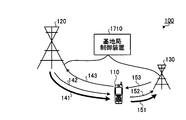
- FIG. 1 is a diagram illustrating a configuration of a communication system according to the first embodiment.
- the communication system 100 includes a terminal device 110, a first base station 120, and a second base station 130.
- the terminal device 110 is a mobile station capable of wireless communication, such as a mobile phone.
- the communication method of the terminal device 110 is, for example, full duplex in which uplink and downlink communication are performed at the same time.
- the first base station 120 accommodates a first cell
- the second base station 130 accommodates a second cell different from the first cell.
- the terminal device 110 selects a base station for each of the uplink and the downlink, and communicates with the network via the selected base station. For example, the terminal device 110 communicates with the network via one base station (for example, the first base station 120) for both uplink and downlink. In addition, depending on the communication environment, the terminal device 110 communicates with the network via different base stations for the uplink and the downlink.
- the terminal device 110 communicates with the network via different base stations for the uplink and the downlink.
- the terminal device 110 communicates with the network via the first base station 120 for the downlink and communicates with the network via the second base station 130 for the uplink.
- the terminal device 110 receives the downlink data 141 from the first base station 120 in the downlink. In addition, the terminal device 110 transmits and receives control information for receiving the downlink data 141 to and from the first base station 120. Specifically, the terminal device 110 receives the downlink control information 142 for receiving the downlink data 141 from the first base station 120 and also transmits the uplink control information 143 for transmitting the downlink data 141 to the first base station. 120.
- the terminal device 110 transmits the uplink data 151 to the second base station 130 in the uplink. In addition, the terminal device 110 transmits and receives control information for transmitting the uplink data 151 to and from the second base station 130. Specifically, the terminal device 110 transmits the uplink control information 152 for transmitting the uplink data 151 to the second base station 130, and transmits the downlink control information 153 for transmitting the uplink data 151 to the second base station. Receive from 130.
- FIG. 2 is a diagram of a configuration example of the terminal device according to the first embodiment.
- the terminal device 110 includes an antenna 210, a circulator 220, frequency conversion circuits 230 and 240, an analog / digital conversion circuit 250, a digital / analog conversion circuit 260, a downlink reception unit 270, and uplink transmission. Part 280.
- the antenna 210 is an antenna for performing wireless communication with a base station such as the first base station 120 or the second base station 130.
- Antenna 210 outputs a signal received wirelessly to circulator 220.
- Antenna 210 transmits the signal output from circulator 220 wirelessly.
- Circulator 220 outputs the signal output from antenna 210 to frequency conversion circuit 230.
- Circulator 220 outputs the signal output from frequency conversion circuit 240 to antenna 210.
- the frequency conversion circuit 230 converts the high-frequency signal from the circulator 220 into a baseband, and outputs the signal converted into the baseband to the analog-digital conversion circuit 250.
- the frequency conversion circuit 240 converts the baseband signal from the digital-analog conversion circuit 260 into a high frequency, and outputs the signal converted into the high frequency to the circulator 220.
- the analog / digital conversion circuit 250 (A / D: Analog / Digital) converts the analog signal output from the frequency conversion circuit 230 into a digital signal and outputs the digital signal to the downlink reception unit 270.
- the digital / analog conversion circuit 260 (D / A: Digital / Analog) converts the digital signal output from the uplink transmission unit 280 into an analog signal and outputs the analog signal to the frequency conversion circuit 240.
- the downlink receiving unit 270 includes two systems of downlink receiving circuits 271 and 272. For example, when the terminal apparatus 110 communicates on the downlink via the first base station 120, the downlink reception circuit 271 receives downlink data and related control information from the first base station 120. Further, the downlink receiving circuit 272 receives control information related to uplink data transmission to the second base station 130.
- the downlink reception circuit 271 demodulates the signal output from the analog-digital conversion circuit 250 using control information related to the first base station 120, and transmits the signal transmitted from the first base station 120. Receive.
- the downlink reception circuit 271 outputs a data signal (reception data) of the received signals to the upper circuit, and outputs control information to be fed back to the first base station 120 such as delivery confirmation information to the uplink transmission circuit 281.
- the downlink reception circuit 272 demodulates the signal output from the analog-digital conversion circuit 250 using control information related to the second base station 130 and receives the signal transmitted from the second base station 130.
- the downlink reception circuit 272 outputs control information such as acknowledgment information and resource allocation information necessary for uplink data transmission to the uplink transmission circuit 282 that actually performs uplink data transmission.
- the upstream transmission unit 280 includes two systems of upstream transmission circuits 281 and 282 and an addition circuit 283. For example, when the terminal apparatus 110 communicates with the uplink via the second base station 130, the uplink transmission circuit 281 transmits uplink data and related control information to the second base station 130. Further, the uplink transmission circuit 282 transmits control information related to downlink data transmission to the first base station 120. The adder circuit 283 adds the transmission signals output from the uplink transmission circuits 281 and 282 to generate a baseband signal.
- the uplink transmission circuit 282 modulates transmission data using the control information related to the second base station 130 output from the downlink reception circuit 272, and outputs the modulated signal to the addition circuit 283.
- the uplink transmission circuit 281 modulates control information related to downlink data output from the downlink reception circuit 271, and outputs a modulated signal to the addition circuit 283.
- the adder circuit 283 adds the signals output from the uplink transmission circuits 281 and 282 and outputs the added signal to the digital-analog conversion circuit 260 as a baseband signal.
- Each of the downlink receiving unit 270 and the uplink transmitting unit 280 can be realized by, for example, a DSP (Digital Signal Processor). However, the downlink receiving unit 270 and the uplink transmitting unit 280 can be realized by one DSP.
- DSP Digital Signal Processor
- the terminal apparatus 110 uses different base stations for uplink and downlink data transmission. Thereby, communication quality can be improved even when the optimum base station is different between the uplink and the downlink.
- the terminal device 110 communicates with a base station (for example, the first base station 120) having stronger received power in the terminal device 110 in the downlink.
- the terminal apparatus 110 communicates with a base station (for example, the second base station 130) having a smaller propagation loss and stronger received power at the base station for the uplink.
- control information for performing data transmission can be bidirectionally transmitted to each base station, thereby simplifying the scheduling process at each base station.
- the scheduling process in each base station can be performed independently for each base station without transferring control information between the base stations. For this reason, the scheduling process can be stably performed by a simple process while avoiding a delay due to transfer of control information or the like.
- the signal power is small because the control information has less traffic than the data. Therefore, even if the control information is transmitted bidirectionally, the signal loss is small and the influence on the communication quality is small.
- different base stations are used for uplink and downlink data transmission, and control information is transmitted bi-directionally with each base station, thereby simplifying scheduling processing at each base station and stably communicating. It can be performed.
- the terminal device 110 may transmit uplink data and a control signal to the second base station 130 at the same time as transmitting control information to the first base station 120.
- the terminal device 110 may receive a control signal from the second base station 130 simultaneously with receiving downlink data and control information from the first base station 120.
- the terminal device 110 it is difficult to make the timings of communication with the first base station 120 and communication with the second base station 130 completely coincide. Therefore, when communicating with different base stations in the same link direction, for example, two communication circuits that operate independently in the terminal device 110 are mounted (for example, the downlink receiving circuits 271 and 272 and the uplink transmitting circuit 281 in FIG. 2). , 282).
- the first base station 120 and the second base station 130 perform communication with the terminal device 110 in a time division manner. Since the basic configuration of the communication system according to the second embodiment is the same as that of the communication system according to the first embodiment (see FIG. 1), the description thereof is omitted.
- FIG. 3 is a diagram of a configuration example of the terminal device according to the second embodiment.
- the terminal apparatus 110 according to the second embodiment includes a downlink reception circuit 310, an uplink transmission circuit 320, and a time division control circuit instead of the downlink reception unit 270 and the uplink transmission unit 280 illustrated in FIG. 330 is provided.
- the downlink reception circuit 310 and the uplink transmission circuit 320 can be realized by a DSP, for example.
- the downlink receiving circuit 310 has the same function as the downlink receiving unit 270 shown in FIG. That is, the downlink reception circuit 310 transmits downlink data from the first base station 120, receives control information for uplink data transmission from the first base station 120, and outputs the control information to the uplink transmission unit.
- the uplink transmission circuit 320 has the same function as the uplink transmission unit 280 shown in FIG. That is, the uplink transmission circuit 320 transmits uplink data to the second base station 130 and transmits control information related to reception of downlink data from the first base station 120 to the first base station 120.
- the time division control circuit 330 controls the downlink reception circuit 310 and the uplink transmission circuit 320 to switch the base station to be communicated in a time division manner. For example, the terminal apparatus 110 is notified of allocation of different time resources from the first base station 120 and the second base station 130.
- the time division control circuit 330 causes the downlink reception circuit 310 and the uplink transmission circuit 320 to perform (downlink data) communication with the first base station 120 according to the time resource notified from the first base station 120. Further, the time division control circuit 330 causes the downlink reception circuit 310 and the uplink transmission circuit 320 to perform (uplink data) communication with the second base station 130 based on the time resource notified from the second base station 130.
- FIG. 4 is a diagram illustrating allocation of time resources according to the second embodiment.
- the horizontal axis represents radio frames “0” to “9” that are time resources obtained by time-sharing radio resources.
- 3 assigns radio frames “0” to “9” to either the downlink reception circuit 310 or the uplink transmission circuit 320, respectively, so that the communication by the downlink reception circuit 310 and the uplink transmission circuit 320 are performed. Switching between communication and time-sharing.
- the downlink channel 410 is a channel related to downlink communication performed by the downlink reception circuit 310 of the terminal device 110 with the first base station 120.
- the downlink channel 410 includes a downlink control channel 411, a downlink data channel 412, and an uplink control channel 413.
- even-numbered radio frames “0”, “2”, “4”, “6”, and “8” are assigned to the downlink channel 410.
- control information 411 a of the downlink control channel 411 and data 412 a of the downlink data channel 412 are transmitted from the first base station 120 to the terminal device 110.
- the control information 411a is control information for the terminal device 110 to receive the data 412a, and is information indicating a radio resource allocated to transmit the data 412a, for example.
- the control information 413 a of the uplink control channel 413 is transmitted from the terminal device 110 to the first base station 120.
- the control information 413a is, for example, delivery confirmation information (Ack or Nack) for the data 412a.
- the uplink channel 420 is a channel related to uplink communication performed by the uplink transmission circuit 320 of the terminal device 110 with the second base station 130.
- the uplink channel 420 includes a downlink control channel 421, an uplink data channel 422, and an uplink control channel 423.
- odd-numbered radio frames “1”, “3”, “5”, “7”, and “9” are assigned to the uplink channel 420.
- the control information 421a of the downlink control channel 421 is transmitted from the second base station 130 to the terminal device 110.
- the control information 421a is control information for the terminal device 110 to transmit the data 422a.
- the control information 421a is information indicating a radio resource allocated to transmit the data 422a.
- the data 422 a of the uplink data channel 422 is transmitted from the terminal device 110 to the second base station 130.
- the control information 423 a of the uplink control channel 423 is transmitted from the terminal device 110 to the second base station 130.
- the uplink control channel 423 is information for requesting the second base station 130 to allocate radio resources for transmission of data next to the data 422a, for example.
- FIG. 5 is a flowchart of an example of the operation of the terminal device according to the second embodiment.
- the terminal device 110 performs the following steps. First, each pilot signal transmitted from the first base station 120 and the second base station 130 is received, and each received power from the first base station 120 and the second base station 130 is measured (step S501).
- a downlink base station is selected from the first base station 120 and the second base station 130 based on each received power measured in step S501 (step S502).
- step S502 for example, a base station having a large received power among the first base station 120 and the second base station 130 is selected as a downlink base station.
- each transmission power information transmitted from the first base station 120 and the second base station 130 is received (step S503).
- Each transmission power information transmitted from the first base station 120 and the second base station 130 indicates the transmission power of each pilot signal transmitted from the first base station 120 and the second base station 130, respectively.
- propagation loss of each of the first base station 120 and the second base station 130 is calculated based on each received power measured in step S501 and each transmission power information received in step S503 (step S504). ). If the reception power measured in step S501 is TP and the transmission power indicated by the transmission power information received in step S503 is RP, the propagation loss PL calculated in step S504 can be indicated by TP-RP, for example. .
- an uplink base station is selected from the first base station 120 and the second base station 130 (step S505).
- a base station with a small propagation loss among the first base station 120 and the second base station 130 is selected as an uplink base station.
- step S506 it is determined whether or not the base station selected in step S502 is different from the base station selected in step S505 (step S506). If each base station is the same (step S506: No), the series of operations is terminated. In this case, the terminal device 110 communicates with either the first base station 120 or the second base station 130 on the uplink and the downlink.
- step S506 If each base station is different in step S506 (step S506: Yes), an asymmetric transmission request for requesting asymmetric transmission is transmitted to the currently communicating base station (step S507), and the series of operations is terminated. To do.
- the asymmetric transmission request transmitted in step S507 includes information on the base station corresponding to the uplink and the base station corresponding to the downlink of the terminal apparatus 110.
- the asymmetric transmission request includes information indicating that the first base station 120 is a downlink base station and the second base station 130 is an uplink base station.
- the base station that has received the asymmetric transmission request controls the second base station 130 to receive the uplink data from the terminal device 110 based on the asymmetric transmission request, and transmits the downlink data to the terminal device 110.
- the first base station 120 is controlled. For example, when the base station that has received the asymmetric transmission request is the first base station 120, the first base station 120 performs downlink communication of the terminal device 110 and performs uplink communication of the terminal device 110.
- the second base station 130 is controlled as described above.
- FIG. 6 is a diagram of an example of processing of the communication system according to the second embodiment.
- the terminal device 110 in a state where the terminal device 110 is communicating with the first base station 120, the first base station 120 is selected as a downlink base station in step S502 of FIG. 5, and the second base station 130 is selected in step S505. Is selected as the uplink base station.
- the terminal device 110 transmits an asymmetric transmission request (request signal) to the first base station 120 in step S507 of FIG.
- the asymmetric transmission request transmitted by the terminal device 110 includes information on the target base station indicating the base station corresponding to the uplink and the base station corresponding to the downlink in the asymmetric transmission.
- the first base station 120 includes a terminal communication unit 611, a time division control unit 612, a wireless scheduler 613, and an inter-base station communication unit 614.
- the terminal communication unit 611 receives the asymmetric transmission request transmitted from the terminal device 110 and outputs the request to the time division control unit 612.
- the time division control unit 612 allocates time resources to the uplink and the downlink based on the information of the target base station included in the asymmetric transmission request output from the terminal communication unit 611.
- the time division control unit 612 assigns odd-numbered radio frames “1”, “3”, “5”, “7”, “9” to the uplink, and even-numbered radio frames to the downlink. Frames “0”, “2”, “4”, “6”, “8” are assigned (see FIG. 4).
- the time division control unit 612 notifies the radio scheduler 613 of the time resource allocated to the downlink.
- the time division control unit 612 notifies the second base station 130 of the asymmetric transmission request via the inter-base station communication unit 614.
- the asymmetric transmission request transmitted by the time division control unit 612 includes link direction information indicating that the second base station 130 supports uplink, and information on time resources allocated to the uplink. .
- the radio scheduler 613 performs downlink scheduling from the first base station 120 to the terminal device 110 using the time resource notified from the time division control unit 612.
- the first base station 120 performs downlink communication with the terminal device 110 based on the result of scheduling by the wireless scheduler 613.
- the second base station 130 includes an inter-base station communication unit 621 and a wireless scheduler 622.
- the inter-base station communication unit 621 receives the asymmetric transmission request transmitted from the first base station 120.
- the inter-base station communication unit 621 notifies the radio scheduler 622 of the link direction and time resource included in the received asymmetric transmission request.
- the radio scheduler 622 performs uplink scheduling from the terminal device 110 to the second base station 130 based on the time resource notified from the inter-base station communication unit 621.
- the second base station 130 performs uplink communication with the terminal device 110 based on the scheduling result by the radio scheduler 622.
- the transmission of the asymmetric transmission request between the terminal device 110 and the first base station 120 is performed via the mutual wireless communication interface. Further, the transmission of the asymmetric transmission request between the first base station 120 and the second base station 130 is performed via the mutual communication interface, and is realized by, for example, wired communication.
- FIG. 7 is a diagram showing a modification of the processing of the communication system shown in FIG.
- the communication system 100 includes a terminal device 110, a first base station 120, a second base station 130, and a third base station 710.
- the second base station 130 is selected as an uplink base station by step S502 in FIG. 5, and the third base station 710 is selected by step S505.
- the third base station 710 is selected by step S505.
- it is selected as a downlink base station.
- the terminal apparatus 110 transmits an asymmetric transmission request to the first base station 120 in step S507 of FIG.
- the time division control unit 612 transmits the asymmetric transmission request to the second base station 130 and the third base station 710 via the inter-base station communication unit 614.
- the asymmetric transmission request notified to the second base station 130 includes link direction information indicating that the second base station 130 supports uplink, and information of time resources allocated to the uplink. Yes.
- the asymmetric transmission request notified to the third base station 710 includes link direction information indicating that the third base station 710 supports downlink, and information of time resources allocated to the downlink. Yes.
- the third base station 710 includes an inter-base station communication unit 711 and a wireless scheduler 712.
- the inter-base station communication unit 711 receives the asymmetric transmission request transmitted from the first base station 120.
- the inter-base station communication unit 711 notifies the radio scheduler 712 of the link direction and time resource included in the received asymmetric transmission request.
- the radio scheduler 712 performs downlink scheduling from the third base station 710 to the terminal device 110 according to the time resource notified from the inter-base station communication unit 711.
- the third base station 710 performs downlink communication with the terminal device 110 based on the scheduling result by the wireless scheduler 712.
- the base station that receives the asymmetric transmission request from the terminal apparatus 110 may not be a base station corresponding to the uplink and the downlink.
- uplink communication and downlink communication are performed in a time-sharing manner. Thereby, it is possible to avoid the occurrence of communication with different base stations in the same link direction.
- the same effects as those of the communication system 100 according to the first embodiment can be obtained, and the communication circuit of the terminal device 110 can be simplified to reduce the manufacturing cost and power consumption of the terminal device 110.
- the communication circuit of the terminal device 110 can be simplified to reduce the manufacturing cost and power consumption of the terminal device 110.
- it is possible to secure signal transmission power and improve communication quality since it is possible to secure signal transmission power and improve communication quality.
- FIG. 8 is a diagram of an example of the operation of the communication system according to the third embodiment.
- the first base station 120 includes a traffic measurement unit 810 in addition to the configuration shown in FIG.
- the traffic measurement unit 810 measures the amount of uplink traffic in the terminal device 110 and the amount of downlink traffic in the terminal device 110. For example, the traffic measurement unit 810 acquires and acquires downlink request information transmitted from the terminal apparatus 110 to the first base station 120, uplink request information transmitted from the terminal apparatus 110 to the second base station 130, and the like. Each traffic volume is measured based on the requested information.
- the traffic measurement unit 810 notifies the time division control unit 612 of each measured traffic volume.
- notification of each traffic amount from the traffic measurement unit 810 to the time division control unit 612 may be performed periodically or when the first base station 120 receives an asymmetric transmission request from the terminal device 110. May be.
- the time division control unit 612 calculates the ratio between the uplink data rate in the terminal device 110 and the downlink data rate in the terminal device 110 based on each traffic amount notified from the traffic measurement unit 810. Then, the time division control unit 612 allocates time resources to the uplink and the downlink of the terminal apparatus 110 so as to be closest to the calculated data rate ratio.
- the time division control unit 612 has a ratio of the downlink data rate to the uplink data rate of 3: 1 In this case, the time division control unit 612 performs allocation so that the ratio between the time resource allocated to the downlink and the time resource allocated to the uplink is also 3: 1 (see, for example, FIG. 9).
- FIG. 9 is a diagram illustrating time resource allocation according to the third embodiment.
- the downlink data rate is 384 [kbps]
- the uplink data rate is 128 [kbps]
- the ratio of the downlink and uplink data rates is 3: 1.
- the time division control unit 612 transmits radio frames “0”, “2”, “3”, “4”, “6”, “7”, “8” to the downlink channel 410. assign. In addition, the time division control unit 612 assigns radio frames “1”, “5”, and “9” to the uplink channel 420.
- the ratio of the time resource allocated to the downlink and the time resource allocated to the uplink is approximately 3: 1.
- the allocation of downlink and uplink time resources is dynamically changed based on the amount of upper and lower traffic.
- time resources are allocated to the uplink and the downlink in the terminal device 110 based on the traffic amounts of uplink data and downlink data.
- time resources can be efficiently allocated to the uplink and the downlink.
- the difference in traffic volume between the uplink and the downlink is large. For this reason, time resources can be efficiently used by allocating time resources at a rate corresponding to each traffic amount of uplink data and downlink data.
- FIG. 10 is a diagram of an example of the operation of the communication system according to the fourth embodiment. 10, the same components as those illustrated in FIG. 6 are denoted by the same reference numerals, and description thereof is omitted.
- the terminal device 110 according to the fourth embodiment includes an interference power measurement unit 1011.
- the second base station 130 according to the fourth embodiment includes an interference power measurement unit 1012 in addition to the configuration illustrated in FIG.
- the interference power measurement unit 1011 of the terminal apparatus 110 measures the downlink interference power from the first base station 120 to the terminal apparatus 110 for each radio frame obtained by time division of radio resources. For example, the interference power measurement unit 1011 measures the interference power based on a signal (for example, a pilot signal) transmitted from the first base station 120. The interference power measurement unit 1011 notifies the first base station 120 of the measured interference power.
- a signal for example, a pilot signal
- the interference power measurement unit 1012 of the second base station 130 measures the uplink interference power from the terminal device 110 to the second base station 130 for each radio frame obtained by time division of radio resources. For example, the interference power measurement unit 1012 measures the interference power based on a signal (for example, a pilot signal) transmitted from the terminal device 110. The interference power measurement unit 1012 notifies the first base station 120 of the measured interference power.
- a signal for example, a pilot signal
- the notification of the interference power from the interference power measurement unit 1011 to the first base station 120 may be performed periodically or when the terminal device 110 transmits an asymmetric transmission request to the first base station 120. May be.
- the interference power measurement unit 1012 may notify the first base station 120 of interference power periodically, or when the interference power measurement unit 1012 receives an asymmetric transmission request from the first base station 120. You may go to
- the time division control unit 612 of the first base station 120 determines the uplink based on the downlink interference power notified from the terminal device 110 and the uplink interference power notified from the second base station 130. A time resource is allocated to each downlink.
- the time division control unit 612 preferentially allocates radio frames with low downlink interference power to the downlink. Also, the time division control unit 612 preferentially assigns radio frames with small uplink interference power to the uplink based on the uplink interference power for each radio frame notified from the second base station 130.
- the notification of the interference power between the terminal device 110 and the first base station 120 is performed via the mutual wireless communication interface.
- the notification of the interference power between the first base station 120 and the second base station 130 is performed through the mutual communication interface, and is realized by, for example, wired communication.
- FIG. 11 is a diagram illustrating an example of time resource allocation according to the fourth embodiment.
- the interference power characteristic 1110 indicates an average value of downlink interference power from the first base station 120 to the terminal device 110 for each radio frame. This average value is, for example, an average value calculated at regular intervals.
- the interference power characteristic 1110 is relatively small in the radio frames “0”, “1”, “4”, “5”, “8”, “9”, and the radio frames “2”, “3”, “ 6 "and” 7 "are relatively large.
- the interference power characteristic 1120 indicates the average value of the uplink interference power from the terminal device 110 to the second base station 130 for each radio frame. This average value is, for example, an average value calculated at regular intervals.
- the interference power characteristic 1120 is relatively large in the radio frames “0”, “1”, “4”, “5”, “8”, “9”, and the radio frames “2”, “3”, “6”, “7” is relatively small.
- the time division control unit 612 transmits radio frames “0”, “1”, “4”, “5”, “8”, and “9” with small interference power characteristics 1110 from the first base station 120 to the terminal device 110. Assign to the downlink. In addition, the time division control unit 612 assigns radio frames “2”, “3”, “6”, and “7” with small interference power characteristics 1120 to the uplink from the terminal device 110 to the second base station 130. In this manner, the time division control unit 612 dynamically allocates time resources so that the interference power becomes smaller based on the measured interference power.
- time resources are allocated to the uplink and the downlink in the terminal device 110 based on the interference power of uplink data and downlink data. Accordingly, it is possible to preferentially allocate time resources with low interference power to the uplink and the downlink, so that communication quality can be improved.
- a part of the control channel is transmitted / received using a base station different from the optimum base station.
- the first base station 120 is the optimal base station for the downlink in the terminal device 110
- the downlink control information 153 is transmitted from the second base station 130 to the terminal device 110.
- the second base station 130 is the optimal base station, but the uplink control information 143 (see FIG. 1) is transmitted from the terminal device 110 to the first base station 120.
- the transmission power is larger than when transmitted to the optimal base station. For this reason, it is considered that interference between the first base station 120 and the second base station 130 due to the downlink control information 153 and the uplink control information 143 occurs. In particular, when the transmission power of the uplink control information 143 increases, it is conceivable that interference with the communication of the second base station 130 increases and the communication quality deteriorates.
- FIG. 12 is a diagram illustrating processing of the communication system according to the fifth embodiment.
- the radio scheduler 613 of the first base station 120 notifies the second base station 130 of radio resources allocated to the downlink uplink control channel in the terminal device 110 (uplink control channel resource information).
- the radio scheduler 622 of the second base station 130 allocates a radio resource different from the radio resource notified from the radio scheduler 613 of the first base station 120 to each communication of the second base station 130. For example, the wireless scheduler 622 prohibits subsequent use of the wireless resource notified from the wireless scheduler 613. In addition, when the radio resource notified from the radio scheduler 613 has already been allocated, the radio scheduler 622 performs reallocation to another free time resource.
- FIG. 13 is a diagram illustrating an example of time resource allocation according to the fifth embodiment.
- the horizontal axis in FIG. 13 indicates a radio frame (time resource).
- the vertical axis in FIG. 13 indicates frequency resources.
- the downlink resource 1310 indicates a radio resource allocated to the downlink of the terminal device 110.
- the downlink resource 1310 includes a control channel resource 1311 and a data channel resource 1312.
- the radio resource 1311 a among the control channel resources 1311 is a radio resource allocated to the downlink uplink control channel in the terminal device 110.
- the uplink resource 1320 indicates a radio resource allocated to the uplink of the terminal device 110.
- the uplink resource 1320 includes a control channel resource 1321 and a data channel resource 1322.
- the radio resource 1321a among the control channel resources 1321 is the same radio resource as the radio resource 1311a of the control channel resource 1311.
- the radio scheduler 613 of the first base station 120 notifies the second base station 130 of the radio resource 1321a allocated to the downlink uplink control channel in the terminal device 110.
- the radio scheduler 622 of the second base station 130 allocates radio resources different from the radio resource 1321a to each communication of the second base station 130 based on the notification from the radio scheduler 613 of the first base station 120.
- the first base station 120 transmits the radio resource allocated to the control information received from the terminal device 110 for transmission of downlink data to the second base station 130. Notice. Then, the second base station 130 allocates a radio resource different from the time resource notified from the first base station 120 to each communication in the second base station 130. Thereby, the interference with the communication of the 2nd base station 130 by the increase in the transmission power of a control signal can be avoided.
- the second base station 130 may notify the first base station 120 of radio resources allocated to control information received from the terminal device 110 for receiving uplink data.
- the first base station 120 allocates a radio resource different from the time resource notified from the second base station 130 to each communication in the first base station 120. Thereby, the interference to the communication of the 1st base station 120 by the increase in the transmission power of a control signal can be avoided.
- FIG. 14 is a diagram illustrating an example of overlapping of uplink and downlink timings. Even if different radio frames are assigned to the uplink and the downlink, if the timing is different between the downlink communication and the uplink communication, the uplink and downlink communications may overlap in time. It is done.
- the uplink and downlink communications overlap in time.
- only one of the downlink and uplink can be communicated.
- FIG. 15 is a diagram illustrating processing of the communication system according to the sixth embodiment.
- the terminal device 110 measures the communication timing in the first base station 120 based on the pilot signal periodically transmitted from the first base station 120. Further, the terminal device 110 measures the communication timing in the second base station 130 based on the pilot signal periodically transmitted from the second base station 130.
- the terminal device 110 transmits to the first base station 120 an asymmetric transmission request including information on each communication timing of the measured first base station 120 and second base station 130.
- the time division control unit 612 allocates time resources to the uplink and the downlink based on the communication timing information of the first base station 120 and the second base station 130 included in the asymmetric transmission request. Specifically, the time division control unit 612 sets the guard time based on each communication timing so that the downlink communication timing by the first base station 120 and the uplink communication timing by the second base station 130 do not overlap. Allocate resources.
- FIG. 16 is a diagram illustrating an example of time resource allocation according to the sixth embodiment. 16, the same parts as those shown in FIG. 4 are denoted by the same reference numerals, and the description thereof is omitted.
- radio frames “0”, “1”, “4”, “5”, “8”, and “9” are assigned to the downlink channel 410.
- Radio frames “2”, “3”, “6”, and “7” are assigned to the uplink channel 420.
- the time division control unit 612 of the first base station 120 sets the guard time based on each timing so that the downlink communication timing by the first base station 120 and the uplink communication timing by the second base station 130 do not overlap. Allocate time resources to have. Here, a sufficiently long time resource is allocated to the downlink so that the downlink and uplink communication timings do not overlap.
- the terminal device 110 measures the communication timing of the first base station 120 and the communication timing of the second base station 130. And the 1st base station 120 and the 2nd base station 130 allocate a time resource so that it may have a guard time based on each timing measured by the terminal device 110 with respect to an uplink and a downlink. As a result, even if there is a discrepancy between the communication timing of the first base station 120 and the communication timing of the second base station 130, a guard time is set so that the uplink and the downlink do not overlap in time, thereby improving communication quality. Can be made.
- the first base station 120 and the second base station 130 communicate with each other via a backbone network, for example.
- the first base station 120 and the second base station 130 may be included in the same base station.
- FIG. 17 is a diagram showing a modification of the communication system shown in FIG.
- the communication system 100 includes a base station control device 1710 in addition to the configuration shown in FIG. 1.
- the first base station 120 and the second base station 130 are connected to the base station controller 1710 via a dedicated line or the like.
- the base station control device 1710 performs communication by controlling the first base station 120 and the second base station 130.
- FIG. 18 is a diagram showing an example of processing of the base station shown in FIG.
- a base station 1800 illustrated in FIG. 18 is a base station including the first base station 120, the second base station 130, and the base station control device 1710 illustrated in FIG.
- the base station 1800 includes a terminal communication unit 1811, a time division control unit 1812, a radio scheduler 1813, and a radio scheduler 1814.
- the terminal communication unit 1811 has a configuration corresponding to the terminal communication unit 611 illustrated in FIG.
- the terminal communication unit 1811 is realized by the first base station 120 and the second base station 130, receives the asymmetric transmission request transmitted from the terminal device 110, and outputs the request to the time division control unit 1812.
- the time division control unit 1812 has a configuration corresponding to the time division control unit 612 shown in FIG.
- the time division control unit 1812 allocates time resources to the uplink and the downlink based on the information of the target base station included in the asymmetric transmission request output from the terminal communication unit 1811.
- the time division control unit 1812 notifies the radio scheduler 1813 of the time resource allocated to the downlink.
- the time division control unit 1812 notifies the radio scheduler 1814 of the time resource allocated to the downlink.
- the wireless scheduler 1813 has a configuration corresponding to the wireless scheduler 613 shown in FIG.
- the radio scheduler 1813 performs downlink scheduling from the first base station 120 to the terminal device 110 using the time resource notified from the time division control unit 1812.
- the base station 1800 performs downlink communication with the terminal device 110 based on the result of scheduling by the radio scheduler 1813.
- the wireless scheduler 1814 has a configuration corresponding to the wireless scheduler 622 shown in FIG.
- the radio scheduler 1814 performs uplink scheduling from the terminal apparatus 110 to the second base station 130 based on the time resource notified from the time division control unit 1812.
- the base station 1800 performs uplink communication with the terminal device 110 based on the result of scheduling by the radio scheduler 1814.
Landscapes
- Engineering & Computer Science (AREA)
- Computer Networks & Wireless Communication (AREA)
- Signal Processing (AREA)
- Mobile Radio Communication Systems (AREA)
Abstract
Priority Applications (6)
| Application Number | Priority Date | Filing Date | Title |
|---|---|---|---|
| EP09847349.9A EP2456272A4 (fr) | 2009-07-17 | 2009-07-17 | Dispositif formant terminal, système de communication et procédé de communication |
| JP2011522673A JP5488601B2 (ja) | 2009-07-17 | 2009-07-17 | 端末装置、通信システムおよび通信方法 |
| KR1020127000407A KR101383513B1 (ko) | 2009-07-17 | 2009-07-17 | 단말 장치, 통신 시스템 및 통신 방법 |
| CN200980160456.1A CN102474851B (zh) | 2009-07-17 | 2009-07-17 | 终端装置、通信系统以及通信方法 |
| PCT/JP2009/062998 WO2011007451A1 (fr) | 2009-07-17 | 2009-07-17 | Dispositif formant terminal, système de communication et procédé de communication |
| US13/341,083 US9730190B2 (en) | 2009-07-17 | 2011-12-30 | Terminal apparatus, communication system, and communication method |
Applications Claiming Priority (1)
| Application Number | Priority Date | Filing Date | Title |
|---|---|---|---|
| PCT/JP2009/062998 WO2011007451A1 (fr) | 2009-07-17 | 2009-07-17 | Dispositif formant terminal, système de communication et procédé de communication |
Related Child Applications (1)
| Application Number | Title | Priority Date | Filing Date |
|---|---|---|---|
| US13/341,083 Continuation US9730190B2 (en) | 2009-07-17 | 2011-12-30 | Terminal apparatus, communication system, and communication method |
Publications (1)
| Publication Number | Publication Date |
|---|---|
| WO2011007451A1 true WO2011007451A1 (fr) | 2011-01-20 |
Family
ID=43449066
Family Applications (1)
| Application Number | Title | Priority Date | Filing Date |
|---|---|---|---|
| PCT/JP2009/062998 WO2011007451A1 (fr) | 2009-07-17 | 2009-07-17 | Dispositif formant terminal, système de communication et procédé de communication |
Country Status (6)
| Country | Link |
|---|---|
| US (1) | US9730190B2 (fr) |
| EP (1) | EP2456272A4 (fr) |
| JP (1) | JP5488601B2 (fr) |
| KR (1) | KR101383513B1 (fr) |
| CN (1) | CN102474851B (fr) |
| WO (1) | WO2011007451A1 (fr) |
Cited By (2)
| Publication number | Priority date | Publication date | Assignee | Title |
|---|---|---|---|---|
| JP2013175893A (ja) * | 2012-02-24 | 2013-09-05 | Kddi Corp | 制御チャネル無線リソース割当装置、及び制御チャネル無線リソース割当プログラム |
| WO2016208296A1 (fr) * | 2015-06-24 | 2016-12-29 | 株式会社Nttドコモ | Dispositif d'utilisateur, station de base et procédé de communication |
Families Citing this family (13)
| Publication number | Priority date | Publication date | Assignee | Title |
|---|---|---|---|---|
| US9232462B2 (en) * | 2009-10-15 | 2016-01-05 | Qualcomm Incorporated | Methods and apparatus for cross-cell coordination and signaling |
| WO2013017295A1 (fr) * | 2011-08-03 | 2013-02-07 | Telefonaktiebolaget L M Ericsson (Publ) | Appareil et procédé de programmation pour un système de communication tdd |
| JP6050028B2 (ja) * | 2012-05-25 | 2016-12-21 | シャープ株式会社 | 端末、基地局、通信方法及び集積回路 |
| US9185587B2 (en) | 2012-10-18 | 2015-11-10 | Apple Inc. | Load estimation in 3GPP networks |
| US8958799B2 (en) * | 2012-10-18 | 2015-02-17 | Apple Inc. | Wireless device based inter radio access technology handover initiation |
| WO2014059666A1 (fr) * | 2012-10-19 | 2014-04-24 | 华为技术有限公司 | Procédé et dispositif de communication |
| EP2945459B1 (fr) | 2013-02-01 | 2018-01-31 | Huawei Technologies Co., Ltd. | Procédé et dispositif d'interaction de données |
| EP2958355B1 (fr) * | 2013-02-15 | 2017-12-20 | Mitsubishi Electric Corporation | Système de communication |
| WO2014162194A1 (fr) * | 2013-04-01 | 2014-10-09 | Marvell World Trade Ltd. | Terminaison de périodes de liaison montante de communication sans fil pour faciliter la réception d'autres communications sans fil |
| CN104737604B9 (zh) * | 2013-06-28 | 2018-12-07 | 华为技术有限公司 | 上行数据的传输方法、无线通信节点和终端 |
| US9319957B1 (en) * | 2013-07-31 | 2016-04-19 | Sprint Spectrum L.P. | Dynamic swapping of uplink and downlink base stations |
| US9608678B1 (en) | 2013-12-19 | 2017-03-28 | Marvell International Ltd. | Method and apparatus for mitigating interference between wireless local area network (WLAN) communications and cellular communications |
| JP6254467B2 (ja) * | 2014-03-20 | 2017-12-27 | Kddi株式会社 | 端末装置、基地局装置、使用アーキテクチャ決定方法、及びコンピュータプログラム |
Citations (6)
| Publication number | Priority date | Publication date | Assignee | Title |
|---|---|---|---|---|
| JPH06224828A (ja) | 1993-01-25 | 1994-08-12 | Kokusai Denshin Denwa Co Ltd <Kdd> | マイクロセル/マクロセル統合移動通信方式 |
| JP2002204470A (ja) * | 2000-12-28 | 2002-07-19 | Mitsubishi Electric Corp | 無線通信システム、無線通信システムの通信制御方法及びその管理方法 |
| JP2005110014A (ja) * | 2003-09-30 | 2005-04-21 | Toshiba Corp | 携帯端末、通信システムおよび通信方法 |
| JP2006054597A (ja) * | 2004-08-10 | 2006-02-23 | Ntt Docomo Inc | スロット割当装置及びその方法 |
| JP2007514367A (ja) | 2003-12-12 | 2007-05-31 | テレフオンアクチーボラゲット エル エム エリクソン(パブル) | 階層セル構造における移動体通信 |
| JP2008053864A (ja) * | 2006-08-22 | 2008-03-06 | Ntt Docomo Inc | 移動通信システムで使用される無線基地局、ユーザ装置及び方法 |
Family Cites Families (26)
| Publication number | Priority date | Publication date | Assignee | Title |
|---|---|---|---|---|
| US5548806A (en) | 1993-01-25 | 1996-08-20 | Kokusai Denshin Denwa Co., Ltd. | Mobile communication system having a cell structure constituted by integrating macro cells and micro cells |
| JPH0730527A (ja) * | 1993-06-25 | 1995-01-31 | Matsushita Electric Ind Co Ltd | 無線パケット伝送装置 |
| JP3392710B2 (ja) * | 1997-06-04 | 2003-03-31 | 株式会社東芝 | 無線通信システム |
| JP3310209B2 (ja) * | 1998-01-28 | 2002-08-05 | 株式会社エヌ・ティ・ティ・ドコモ | 通信チャネル選択方法および基地局装置 |
| FI107218B (fi) * | 1998-10-15 | 2001-06-15 | Nokia Networks Oy | Menetelmä kanavan allokoimiseksi matkaviestinjärjestelmässä |
| JP2001339770A (ja) | 2000-05-30 | 2001-12-07 | Matsushita Electric Ind Co Ltd | 無線通信システム及びそれに用いる通信端末装置 |
| JP2002112326A (ja) * | 2000-10-02 | 2002-04-12 | Ntt Docomo Inc | 無線リソース割当方法及び基地局装置 |
| JP3816334B2 (ja) * | 2000-12-22 | 2006-08-30 | 株式会社エヌ・ティ・ティ・ドコモ | 無線リソース割当方法及び基地局 |
| JP3634797B2 (ja) * | 2001-11-30 | 2005-03-30 | 株式会社東芝 | 無線リンク制御方法および通信システムおよび通信装置 |
| US7463616B1 (en) * | 2002-03-28 | 2008-12-09 | Nortel Networks Limited | Scheduling based on channel change indicia |
| EP1755246A3 (fr) * | 2002-06-28 | 2007-02-28 | Interdigital Technology Corporation | Procédé et système pour déterminer des mécanismes d'échappement corrects pour la réduction de l'interférence dans des systèmes sans fil de la troisième génération |
| JP4592545B2 (ja) * | 2005-08-24 | 2010-12-01 | 株式会社エヌ・ティ・ティ・ドコモ | 送信電力制御方法及び移動通信システム |
| US8694042B2 (en) * | 2005-10-14 | 2014-04-08 | Qualcomm Incorporated | Method and apparatus for determining a base station's transmission power budget |
| KR101202901B1 (ko) | 2005-11-05 | 2012-11-19 | 인하대학교 산학협력단 | 무선 인지 기술을 기반으로 하는 무선통신시스템에서 자원 분배방법 및 이를 지원하는 시스템 |
| JP4430052B2 (ja) | 2006-06-19 | 2010-03-10 | 株式会社エヌ・ティ・ティ・ドコモ | 移動通信システム、ユーザ装置及び送信方法 |
| JP4676533B2 (ja) * | 2006-07-14 | 2011-04-27 | 富士通株式会社 | 移動通信システム及び基地局 |
| KR20080034290A (ko) * | 2006-10-16 | 2008-04-21 | 삼성전자주식회사 | 휴대 인터넷 서비스 시스템 및 방법 |
| JP4485547B2 (ja) * | 2007-06-21 | 2010-06-23 | 株式会社エヌ・ティ・ティ・ドコモ | 移動局、および、移動局における送信電力制御方法 |
| US20090161627A1 (en) * | 2007-12-19 | 2009-06-25 | Freescale Semiconductor, Inc. | Switching communication networks in a mobile device |
| JP5174520B2 (ja) * | 2008-04-18 | 2013-04-03 | 京セラ株式会社 | 移動通信システム、およびチャネル割り当て方法 |
| JP4352281B1 (ja) * | 2008-05-23 | 2009-10-28 | 日本電気株式会社 | 無線通信システム、基地局、基地局間同期方法、プログラム |
| JP5173667B2 (ja) * | 2008-08-11 | 2013-04-03 | 株式会社エヌ・ティ・ティ・ドコモ | ユーザ装置、無線基地局及び方法 |
| US8149813B2 (en) * | 2008-08-13 | 2012-04-03 | Research In Motion Limited | Wireless device having fast-receive mode for measuring received signal strength (RSSI) for higher time division multiple access (TDMA) multislot classes |
| US8391244B2 (en) * | 2008-08-14 | 2013-03-05 | Intel Mobile Communications GmbH | Radio communication terminal devices, radio communication network system, method for operating a radio communication terminal device |
| KR101540815B1 (ko) * | 2008-09-24 | 2015-08-07 | 엘지전자 주식회사 | 무선통신 시스템에서의 상향링크와 하향링크를 위한 무선자원의 관리 방법 |
| US9001783B2 (en) * | 2009-01-05 | 2015-04-07 | Intel Corporation | Dual base stations for wireless communications systems |
-
2009
- 2009-07-17 CN CN200980160456.1A patent/CN102474851B/zh not_active Expired - Fee Related
- 2009-07-17 JP JP2011522673A patent/JP5488601B2/ja active Active
- 2009-07-17 WO PCT/JP2009/062998 patent/WO2011007451A1/fr active Application Filing
- 2009-07-17 EP EP09847349.9A patent/EP2456272A4/fr not_active Withdrawn
- 2009-07-17 KR KR1020127000407A patent/KR101383513B1/ko not_active IP Right Cessation
-
2011
- 2011-12-30 US US13/341,083 patent/US9730190B2/en active Active
Patent Citations (6)
| Publication number | Priority date | Publication date | Assignee | Title |
|---|---|---|---|---|
| JPH06224828A (ja) | 1993-01-25 | 1994-08-12 | Kokusai Denshin Denwa Co Ltd <Kdd> | マイクロセル/マクロセル統合移動通信方式 |
| JP2002204470A (ja) * | 2000-12-28 | 2002-07-19 | Mitsubishi Electric Corp | 無線通信システム、無線通信システムの通信制御方法及びその管理方法 |
| JP2005110014A (ja) * | 2003-09-30 | 2005-04-21 | Toshiba Corp | 携帯端末、通信システムおよび通信方法 |
| JP2007514367A (ja) | 2003-12-12 | 2007-05-31 | テレフオンアクチーボラゲット エル エム エリクソン(パブル) | 階層セル構造における移動体通信 |
| JP2006054597A (ja) * | 2004-08-10 | 2006-02-23 | Ntt Docomo Inc | スロット割当装置及びその方法 |
| JP2008053864A (ja) * | 2006-08-22 | 2008-03-06 | Ntt Docomo Inc | 移動通信システムで使用される無線基地局、ユーザ装置及び方法 |
Non-Patent Citations (3)
| Title |
|---|
| AKIHITO MORIMOTO ET AL.: "LTE-Advanced ni Okeru Kotonaru Cell-Kosei ga Konzai suru Baai no Nobori/Kudari Musen Link Setsuzoku Hoho", INFORMATION AND COMMUNICATION ENGINEERS SOCIETY TAIKAI, vol. B-5-14, 2 September 2008 (2008-09-02), pages 327, XP008148582 * |
| MORIMOTO, AKIHITO; TANNO, MOTOHIRO; KISHIYAMA, YOSHIHISA; MIKI, NOBUHIKO; TAOKA, HIDEKAZU; HIGUCHI, KENICHI; SAWAHASHI, MAMORU: "Downlink/Uplink Radio Link Connection Methods in Heterogeneous Network for LTE-Advanced", IEICE CONFERENCE, 16 September 2008 (2008-09-16), pages 327, XP008148582 |
| See also references of EP2456272A4 |
Cited By (4)
| Publication number | Priority date | Publication date | Assignee | Title |
|---|---|---|---|---|
| JP2013175893A (ja) * | 2012-02-24 | 2013-09-05 | Kddi Corp | 制御チャネル無線リソース割当装置、及び制御チャネル無線リソース割当プログラム |
| WO2016208296A1 (fr) * | 2015-06-24 | 2016-12-29 | 株式会社Nttドコモ | Dispositif d'utilisateur, station de base et procédé de communication |
| JPWO2016208296A1 (ja) * | 2015-06-24 | 2018-04-05 | 株式会社Nttドコモ | ユーザ装置、基地局及び通信方法 |
| US10548162B2 (en) | 2015-06-24 | 2020-01-28 | Ntt Docomo, Inc. | User apparatus, base station, and communication method |
Also Published As
| Publication number | Publication date |
|---|---|
| EP2456272A1 (fr) | 2012-05-23 |
| US20120099458A1 (en) | 2012-04-26 |
| KR101383513B1 (ko) | 2014-04-08 |
| US9730190B2 (en) | 2017-08-08 |
| CN102474851A (zh) | 2012-05-23 |
| EP2456272A4 (fr) | 2017-06-28 |
| CN102474851B (zh) | 2016-04-13 |
| KR20120025590A (ko) | 2012-03-15 |
| JPWO2011007451A1 (ja) | 2012-12-20 |
| JP5488601B2 (ja) | 2014-05-14 |
Similar Documents
| Publication | Publication Date | Title |
|---|---|---|
| JP5488601B2 (ja) | 端末装置、通信システムおよび通信方法 | |
| US11304216B2 (en) | Signaling mechanisms for sub-band scheduling in sidelink | |
| EP3646654B1 (fr) | Procédé et appareil de configuration d'ensemble de ressources de commande dans un système de communication sans fil | |
| US20190014576A1 (en) | Flexible Frame Structure for OFDM Systems | |
| EP3497985A1 (fr) | Contrôle de puissance prête à émettre (pae) en liaison latérale | |
| US20120176978A1 (en) | Method and apparatus for coordinating between cells in wireless communication system | |
| US20130329692A1 (en) | Extending carrier assignment by use of dynamic component carriers | |
| US20150171952A1 (en) | Base station, communication system, mobile terminal, and relay device | |
| CN110943848A (zh) | 一种用于无线网络和多个ue之间的虚拟通信的方法 | |
| US10440635B2 (en) | Network device and user device and methods thereof | |
| US9282583B2 (en) | Base station, wireless communication method, user equipment, and wireless communication system | |
| JP2016501478A (ja) | ビームフォーミングを用いる無線通信システムにおけるスケジューリング情報を送受信する方法及び装置 | |
| WO2012114151A1 (fr) | Activation dynamique de transmissions multipoint coordonnées par l'affectation de porteuses de composants dynamiques | |
| WO2015172838A1 (fr) | Configuration de liaison terrestre sans fil | |
| WO2012114154A1 (fr) | Support de nœuds reconfigurables multi-sauts et mobiles | |
| KR20100060303A (ko) | 기지국 협력 통신 시스템에서 재전송 요청 수행 방법 및 이를 위한 시스템 | |
| JP6150288B2 (ja) | 無線通信システムおよび無線通信方法 | |
| WO2012174828A1 (fr) | Procédé et dispositif de planification | |
| US20090268658A1 (en) | Apparatus and method for relay service in wireless communication system | |
| WO2012114152A1 (fr) | Activation de transmissions de protocole harq en coopération par l'affectation de canaux dcc | |
| WO2011099289A1 (fr) | Dispositif formant relais sans fil et procédé pour relais sans fil | |
| JP2011049784A (ja) | 無線通信システムおよび通信装置 | |
| WO2024102519A1 (fr) | Alignement de temps de réveil cible | |
| WO2013180694A1 (fr) | Procédés et dispositifs dans un système de communication | |
| WO2015013872A1 (fr) | Procédé, appareil et système de configuration de ressources |
Legal Events
| Date | Code | Title | Description |
|---|---|---|---|
| WWE | Wipo information: entry into national phase |
Ref document number: 200980160456.1 Country of ref document: CN |
|
| 121 | Ep: the epo has been informed by wipo that ep was designated in this application |
Ref document number: 09847349 Country of ref document: EP Kind code of ref document: A1 |
|
| WWE | Wipo information: entry into national phase |
Ref document number: 2011522673 Country of ref document: JP |
|
| ENP | Entry into the national phase |
Ref document number: 20127000407 Country of ref document: KR Kind code of ref document: A |
|
| WWE | Wipo information: entry into national phase |
Ref document number: 2009847349 Country of ref document: EP |
|
| NENP | Non-entry into the national phase |
Ref country code: DE |