WO2011004692A1 - 光干渉計を用いた変位計測装置 - Google Patents
光干渉計を用いた変位計測装置 Download PDFInfo
- Publication number
- WO2011004692A1 WO2011004692A1 PCT/JP2010/060433 JP2010060433W WO2011004692A1 WO 2011004692 A1 WO2011004692 A1 WO 2011004692A1 JP 2010060433 W JP2010060433 W JP 2010060433W WO 2011004692 A1 WO2011004692 A1 WO 2011004692A1
- Authority
- WO
- WIPO (PCT)
- Prior art keywords
- reflecting plate
- light
- base
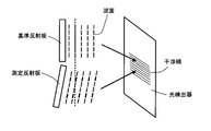
- reflecting
- plate
- Prior art date
- Legal status (The legal status is an assumption and is not a legal conclusion. Google has not performed a legal analysis and makes no representation as to the accuracy of the status listed.)
- Ceased
Links
Images






Classifications
-
- G—PHYSICS
- G01—MEASURING; TESTING
- G01B—MEASURING LENGTH, THICKNESS OR SIMILAR LINEAR DIMENSIONS; MEASURING ANGLES; MEASURING AREAS; MEASURING IRREGULARITIES OF SURFACES OR CONTOURS
- G01B11/00—Measuring arrangements characterised by the use of optical techniques
-
- G—PHYSICS
- G01—MEASURING; TESTING
- G01B—MEASURING LENGTH, THICKNESS OR SIMILAR LINEAR DIMENSIONS; MEASURING ANGLES; MEASURING AREAS; MEASURING IRREGULARITIES OF SURFACES OR CONTOURS
- G01B11/00—Measuring arrangements characterised by the use of optical techniques
- G01B11/26—Measuring arrangements characterised by the use of optical techniques for measuring angles or tapers; for testing the alignment of axes
- G01B11/27—Measuring arrangements characterised by the use of optical techniques for measuring angles or tapers; for testing the alignment of axes for testing the alignment of axes
-
- G—PHYSICS
- G01—MEASURING; TESTING
- G01B—MEASURING LENGTH, THICKNESS OR SIMILAR LINEAR DIMENSIONS; MEASURING ANGLES; MEASURING AREAS; MEASURING IRREGULARITIES OF SURFACES OR CONTOURS
- G01B9/00—Measuring instruments characterised by the use of optical techniques
- G01B9/02—Interferometers
- G01B9/02055—Reduction or prevention of errors; Testing; Calibration
- G01B9/02056—Passive reduction of errors
- G01B9/02061—Reduction or prevention of effects of tilts or misalignment
-
- G—PHYSICS
- G01—MEASURING; TESTING
- G01B—MEASURING LENGTH, THICKNESS OR SIMILAR LINEAR DIMENSIONS; MEASURING ANGLES; MEASURING AREAS; MEASURING IRREGULARITIES OF SURFACES OR CONTOURS
- G01B2290/00—Aspects of interferometers not specifically covered by any group under G01B9/02
- G01B2290/70—Using polarization in the interferometer
Definitions
- the present invention relates to a displacement measuring apparatus using an optical interferometer, and more particularly to a displacement measuring apparatus capable of measuring minute displacement at the nm level.
- Laser interferometers are widely used to measure distance or displacement.
- a light source 34 such as a laser beam
- the light irradiated from the light source 34 is divided into reference light and measurement light, and the reflected reference light and measurement light are reflected.
- a reference reflector 36 that reflects the reference light from the beam splitter 35
- a measurement reflector 37 that reflects the measurement light from the beam splitter 35
- the reference light and the measurement light And a photodetector 39 for detecting the interference light.
- the displacement measuring device 31 using such a laser interferometer includes a light source 34, beam splitters 35 and 35 ′, a photodetector 39, a reference reflector 36, and a fixed portion 32. Is provided, and the measurement reflector 37 is provided on the movable portion 33.
- the fixed part 32 and the movable part 33 are installed and used on an object to be measured such as a plate.
- the measurement reflecting plate is displaced together with the movable portion 33, the wavefront of the interference light is changed as shown in FIG. 9, and the interference light detected by the photodetector is changed.
- displacement amount n ⁇ ⁇ / 2 (1).
- Such a displacement measuring device 31 has the following problems. As shown in FIG. 10, when the movable portion 33 is tilted, the measurement reflecting plate 37 is tilted, and as shown in FIG. 11, between the wavefront of the reflected light of the measurement light and the reflected light of the reference light. Inclination occurs. Fine interference fringes are generated by the inclination of the wavefront. When this interference fringe is generated, the displacement amount cannot be measured by the above equation (1). *
- the present invention proposes a displacement measuring device that can prevent the occurrence of fine interference fringes even when the movable portion is inclined.
- the first base in a displacement measuring apparatus using an optical interferometer, the first base and a second base that is movably installed with respect to the first base, On the first base, a light source, a beam splitter for branching light emitted from the light source into reference light and measurement light, and interference fringes caused by interference between the reference light and the measurement light are detected. On the second base, a first reflecting plate that reflects the reference light and a second reflecting plate that reflects the measurement light are provided on the second base.
- the reflecting surface of the first reflecting plate and the reflecting surface of the second reflecting plate are installed so as to be parallel to each other, and either one of the first reflecting plate or the second reflecting plate Through the third reflector provided on the first base, the beam splitter We propose a displacement measurement apparatus al light is irradiated. *
- the optical axes of the reference light and measurement light branched by the beam splitter are perpendicular to each other.
- the optical axes of the reference light and the measurement light become parallel to each other.
- the reflecting surface of the first reflecting plate and the reflecting surface of the second reflecting plate can be installed so as to be parallel to each other. Since the first reflector and the second reflector are both provided on the second base and the reflecting surfaces are provided in parallel to each other, the wavefront of the reference light and the wavefront of the measuring light Are always parallel to each other.
- the first solving means can prevent the occurrence of fine interference fringes due to the inclination of the wavefront.
- the reflecting surface of the first reflecting plate and the reflecting surface of the second reflecting plate are in substantially the same direction.
- a displacement measuring device installed in this way. With such a configuration, the angle can be detected.
- the second base can be made small, the apparatus can be miniaturized.
- the first reflector and the second reflector may be integrated, that is, a single reflector.
- a step may be provided on one of the reflecting surface of the first reflecting plate and the reflecting surface of the second reflecting plate.
- the detector preferably has a sensor portion divided into a plurality of parts.
- the present invention it is possible to prevent the occurrence of fine interference fringes even when the movable portion is inclined. Thereby, it is possible to obtain a displacement measuring device capable of measuring minute displacement at the nm level.
- FIG. 2 is a schematic diagram showing a state when the movable part is inclined in the displacement measuring apparatus of FIG. 1.
- FIG. 2 is a schematic diagram which shows the 2nd example of the displacement measuring device of this invention.
- It is a schematic diagram which shows the modification of the 2nd example of the displacement measuring device of this invention. It is the figure which observed the signal observed with the photodetector of FIG. 4 with the oscilloscope.
- It is a schematic diagram which shows the modification of the 2nd example of the displacement measuring device of this invention.
- It is a schematic diagram which shows another example of the 2nd example of the displacement measuring device of this invention.
- It is a schematic diagram which shows the conventional displacement measuring device.
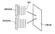
- It is a schematic diagram which shows the mode of interference of reference light and measurement light.
- It is a schematic diagram which shows the problem of the conventional displacement measuring device.
- It is a schematic diagram which shows the mode of interference of the reference light and measurement light in the state shown in FIG.
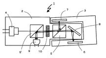
- FIG. 1 shows a first example of the displacement measuring apparatus of the present invention. *
- the displacement measuring device 1 includes a light source 4, a beam splitter 5 that branches light emitted from the light source 4 into measurement light and reference light, a second reflector 7 that reflects measurement light from the beam splitter 5, A first reflecting plate 6 having a reflecting surface arranged in parallel with the reflecting surface of the second reflecting plate 7 and a third reflecting the reference light from the beam splitter 5 toward the first reflecting plate 6.
- a light detector 9 for detecting interference light between the reference light reflected by the first reflector 6 and the measurement light reflected by the second reflector 7, and the light from the light source 4.
- a beam splitter 5 ′ that transmits and reflects the interference light toward the photodetector 9. Further, a ⁇ / 4 wavelength plate 10 may be provided as necessary. *
- the displacement measuring device 1 includes a first base 2 and a second base 3 that is movably installed with respect to the first base 2.
- the first base 2 is provided with a light source 4, beam splitters 5, 5 ′, a third reflecting plate 8, a photodetector 9 and a ⁇ / 4 wavelength plate 10.
- the second base 3 is provided with a first reflecting plate 6 and a second reflecting plate 7.
- the first base 2 is described as a fixed part and the second base is a movable part, the first base 2 may be a movable part and the second base 3 may be a fixed part. *
- the light source 4 includes lenses such as a collimator lens (not shown).
- the light source 4 is controlled by control means (not shown). *
- a prism or the like is used for the beam splitters 5 and 5 '.
- a beam splitter 5 that branches light from the light source 4 into reference light and measurement light
- a beam splitter 5 ′ that reflects interference light toward the photodetector 9.
- a photoelectric conversion element that converts light intensity into an electric signal such as a CCD or a CMOS sensor
- the photodetector 9 is connected to signal processing means (not shown).
- the electric signal generated by the photodetector 9 is processed by a signal processing means (not shown), converted into the number of changes in brightness, and converted into a displacement amount of the second base.
- the photodetector 9 may be one in which the sensor part is divided into two or more parts. *
- the first reflecting plate 6, the second reflecting plate 7, and the third reflecting plate 8 in addition to the reflecting mirror, a highly reflective metal plate, a resin plate, or the like is used.
- the first reflecting plate 6 and the second reflecting plate 7 are provided on the second base 3 and installed so that the reflecting surfaces are parallel to each other. Since the measurement light and the reference light branched by the beam splitter 5 are branched in a direction perpendicular to each other, one of them needs to change the direction of light by the third reflector 8.
- a third reflecting plate 8 is provided between the first reflecting plate 6 and the beam splitter 5 to change the direction of the reference light.
- a third reflecting plate 8 may be provided between the second reflecting plate 7 and the beam splitter 5 to change the direction of the measurement light. Since the third reflector 8 is installed on the first base 2, the positional relationship with the beam splitter 5 and the reflection angle are constant. *
- the ⁇ / 4 wavelength plate 10 may be provided as necessary.
- the light emitted from the light source 4 passes through the ⁇ / 4 wavelength plate 10 and becomes circularly polarized light having a phase of ⁇ / 4.
- the light reflected by the first reflecting plate 6 and the second reflecting plate 7 passes through the ⁇ / 4 wavelength plate 10 and changes from circularly polarized light to linearly polarized light.
- the polarizing prism 5 ′ it is preferable to insert ⁇ / 4 because the loss of light can be suppressed.
- the light returned from the reflecting mirror as linearly polarized light is incident on the polarizing prism 5 ′ at a polarization angle that is 90 degrees different from the linearly polarized light angle of the light source, so that almost all light quantity is reflected by the polarizing prism. Then, the light enters the photodetector 9.
- the displacement measuring apparatus 1 when the second base 3 is inclined, the reflecting surface of the second reflecting plate 7 is also inclined. However, since the first reflecting plate 6 is also installed on the second base 3, the reflecting surface of the first reflecting plate 6 is inclined. Since the first reflecting plate 6 and the second reflecting plate 7 have the same inclination, the reflecting surfaces of the first reflecting plate 6 and the second reflecting plate 7 are always kept parallel. Therefore, no inclination occurs between the wavefront of the reflected light of the reference light and the wavefront of the reflected light of the measurement light. *
- the direction of the reference light reflected by the first reflecting plate 6 is changed by the third reflecting plate 8, passes through the beam splitter 5, and is irradiated toward the photodetector 9 by the beam splitter 5 '. .
- the measurement light reflected by the second reflecting plate 7 is changed in direction by the beam splitter 5 and is irradiated toward the photodetector 9 by the beam splitter 5 ′. Since the third reflector 8 and the beam splitter 5 are installed on the first base and the reflection angle is constant, the measurement light reflected by the first reflector 6 and reflected by the third reflector 8 is used.
- the reflected light and the measurement light reflected by the second reflector and reflected by the beam splitter 5 are not inclined with respect to each other. *
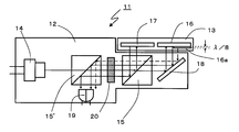
- FIG. 3 shows the structure of a second example of the displacement measuring apparatus of the present invention.
- the displacement measuring device 11 of the second example is installed so that the reflecting surface of the first reflecting plate 16 provided on the second base 13 and the reflecting surface of the second reflecting plate 17 are in substantially the same direction. This is different from the displacement measuring apparatus 1 of the first example.
- the first reflecting plate 16 and the second reflecting plate 17 can be installed side by side.
- the second base 13 of the example displacement measuring device 11 can be made small. As a result, the entire displacement measuring device can be reduced in size.
- a step 16 a may be provided on either the reflecting surface of the reflecting plate 16 or the reflecting surface of the second reflecting plate 17.
- the first reflector 16 is divided into two parts by the step 16a, and a step of ⁇ / 8 is provided on the other half side with respect to the half side.
- a step of ⁇ / 8 is provided on the other half side with respect to the half side.
- FIG. 5 is an observation of the signal read by the photodetector 19 divided into two with an oscilloscope.
- the signal in which the interference light A precedes the interference light B by ⁇ / 4 as shown in FIG. Is detected by the photodetector 19.
- FIG. 4 when displaced in the other direction, as shown in FIG.
- the direction of displacement of the second base 13 can be determined by detecting the phase difference generated in each sensor of the photodetector 19 divided into two.
- a reflecting plate 16 ′ integrated with two reflecting plates may be used.
- the first reflector and the second reflector are divided and installed, it is necessary to match the angles of each other. As the wavelength of the light used becomes shorter, the angle adjustment becomes very strict.
- the integrated reflector 16 makes it easy to adjust the angle, which is effective for a displacement measuring apparatus that uses light having a short wavelength that is difficult to adjust.
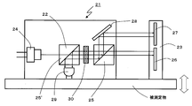
- FIG. 7 A modification of the second example is shown in FIG.
- the displacement measuring device 21 of the modified example of the second example shown in FIG. 7 changes the direction of the measurement light branched by the beam splitter 25 by the third reflecting plate 28 and irradiates the second reflecting plate 27.
- the first reflecting plate 26 and the second reflecting plate 27 are different from the displacement measuring apparatus 11 of the second example in that they are installed perpendicular to the object to be measured. In such a configuration, it is possible to measure the displacement angle when the object to be measured is deformed in the direction of the block arrow. *
- the displacement measuring device 21 can detect a difference in moving distance between the first reflecting plate 26 that reflects the reference light and the second reflecting plate 27 that reflects the measuring light.
- the difference in moving distance is obtained from the number of changes in brightness detected by the photodetector 29.
- the displacement angle can be calculated by obtaining the distance between the reference light spot irradiated on the first reflector 26 and the measurement light spot irradiated on the second reflector 27.
Landscapes
- Physics & Mathematics (AREA)
- General Physics & Mathematics (AREA)
- Instruments For Measurement Of Length By Optical Means (AREA)
- Length Measuring Devices By Optical Means (AREA)
Abstract
【課題】 可動部に傾きが生じても、細かい干渉縞の発生を防止することが可能な変位計測装置を提案する。【解決手段】 変位計測装置1は、第一のベース2と、第一のベース2に対して可動に設置された第二のベース3と、を有している。第一のベース2には、光源4と、光源4から照射される光を測定光と基準光とに分岐するビームスプリッタ5と、ビームスプリッタ5からの基準光を第一の反射板6の方に向けて反射する第三の反射板8と、第一の反射板6で反射された基準光と第二の反射板7で反射された測定光との干渉光を検出する光検出器9およびλ/4波長板10が設けられている。第二のベース3には、反射面が第二の反射板7の反射面と平行に設置されている第一の反射板6およびビームスプリッタ5からの測定光を反射する第二の反射板7が設けられている。
Description
本発明は、光干渉計を用いた変位計測装置に関するものであり、nmレベルの微小変位が計測可能な変位計測装置に関するものである。
距離または変位量を測定するために、レーザ干渉計が広く使用されている。このような干渉計としては、図8に示すように、レーザ光等の光源34と、該光源34から照射された光を基準光と測定光とに分割するとともに反射された基準光および測定光を干渉させるビームスプリッタ35と、該ビームスプリッタ35からの基準光を反射する基準反射板36と、前記ビームスプリッタ35からの測定光を反射する測定反射板37と、前記基準光と前記測定光との干渉光を検出する光検出器39と、を有している。
このようなレーザ干渉計を用いた変位計測装置31は、図8に示すように、固定部32に光源34と、ビームスプリッタ35、35’と、光検出器39と、基準反射板36と、が設けられ、可動部33に測定反射板37が設けられている。そして例えば板材のような被測定物に固定部32及び可動部33を設置して使用される。そして被測定物がブロック矢印の方向に変形すると、可動部33とともに測定反射板が変位して、図9に示すように、干渉光の波面が変化し、光検出器で検出される干渉光の光強度が変化する。測定に用いる光の波長をλとすると、測定反射板が1波長λ変位すると、明→暗→明または暗→明→暗のように明暗の変化が2回発生する。よって、明暗の変化の回数nを検出することにより、 変位量=n×λ/2・・・(1)の式を用いて変位量を計測することができる。
しかしながら、このような変位計測装置31は次のような問題点があった。図10に示すように、可動部33に傾きが生じた場合、測定反射板37に傾きが生じて、図11に示すように、測定光の反射光の波面と基準光の反射光との間に傾きが生じる。そしてこの波面の傾きによって細かい干渉縞が発生する。この干渉縞が発生すると、上記式(1)による変位量の計測ができなくなってしまう。
そこで本発明では、可動部に傾きが生じても、細かい干渉縞の発生を防止することが可能な変位計測装置を提案する。
本発明では第一の解決手段として、光干渉計を用いた変位計測装置において、第一のベースと、該第一のベースに対して可動に設置された第二のベースと、を有し、前記第一のベース上には、光源と、該光源から照射された光を基準光と測定光とに分岐させるビームスプリッタと、前記基準光と前記測定光との干渉によって生じた干渉縞を検出する検出器と、が設けられており、前記第二のベース上には、前記基準光を反射する第一の反射板と、前記測定光を反射する第二の反射板と、が設けられており、前記第一の反射板の反射面と前記第二の反射板の反射面は互いに平行になるように設置されており、前記第一の反射板と前記第二の反射板のいずれか一方は、前記第一のベースに設けられた第三の反射板を介して、前記ビームスプリッタからの光が照射される変位計測装置を提案する。
ビームスプリッタで分岐された基準光と測定光は、光軸が互いに垂直になる。ここで、基準光または測定光のどちらか一方を第三の反射板に照射することにより、基準光と測定光の光軸が互いに平行になる。このことにより、第一の反射板の反射面と第二の反射板の反射面とを互いに平行なるように設置することができる。第一の反射板と第二の反射板は、両方とも第二のベースに設けられており、反射面が互いに平行になるように設けられているので、基準光の波面と測定光の波面とが常に互いに平行となる。よって、上記第一の解決手段により、波面の傾きによる細かい干渉縞の発生を防止することができる。
また、本発明では第二の解決手段として、上記第一の解決手段に加えて、前記第一の反射板の反射面と、前記第二の反射板の反射面と、が略同一方向となるように設置されている変位計測装置を提案する。このような構成であれば、角度検出が可能になる。また、第二のベースを小さくすることができるので、装置の小型化が可能になる。なお、この場合、第一の反射板と第二の反射板を一体化、すなわち一枚の反射板としてもよい。また、第一の反射板の反射面と第二の反射板の反射面のいずれか一方に段差を設けてもよい。これにより、第二のベースの変位の方向を検出することができる。この場合、検出器はセンサ部分が複数に分割されているものが好ましい。
本発明によれば、可動部に傾きが生じても、細かい干渉縞の発生を防止することが可能になる。これにより、nmレベルの微小変位が計測可能な変位計測装置を得ることができる。
本発明の変位計測装置に係る実施形態について、図面に基づいて説明する。まず、図1に本発明の変位計測装置の第一の例を示す。
変位計測装置1は、光源4と、光源4から照射される光を測定光と基準光とに分岐するビームスプリッタ5と、ビームスプリッタ5からの測定光を反射する第二の反射板7と、反射面が第二の反射板7の反射面と平行に設置されている第一の反射板6と、ビームスプリッタ5からの基準光を第一の反射板6の方に向けて反射する第三の反射板8と、第一の反射板6で反射された基準光と第二の反射板7で反射された測定光との干渉光を検出する光検出器9と、光源4からの光を透過し干渉光を光検出器9の方へ反射するビームスプリッタ5’と、を備えている。また、必要に応じてλ/4波長板10を設けてもよい。
変位計測装置1は、第一のベース2と、第一のベース2に対して可動に設置された第二のベース3と、を有している。第一のベース2には、光源4、ビームスプリッタ5、5’、第三の反射板8、光検出器9およびλ/4波長板10が設けられている。第二のベース3には、第一の反射板6および第二の反射板7が設けられている。以下、第一のベース2を固定部、第二のベースを可動部として説明するが、第一のベース2を可動部、第二のベース3を固定部としてもよい。
光源4としては、レーザ光が用いられる。光源4には、図示しないがコリメータレンズ等のレンズ類も含む。光源4は、図示しない制御手段によって、制御される。
ビームスプリッタ5、5’には、プリズム等が用いられる。なお、本実施形態においては、光源4からの光を基準光と測定光とに分岐するビームスプリッタ5と、干渉光を光検出器9の方へ反射するビームスプリッタ5’の2つのビームスプリッタを用いているが、両方の作用をひとつのビームスプリッタにもまとめてもよい。
光検出器9としては、CCDやCMOSセンサ等の、光の強弱を電気信号に変換する光電変換素子が用いられる。光検出器9は、図示しない信号処理手段と接続されている。光検出器9で発生した電気信号は、図示しない信号処理手段によって処理されて、明暗の変化の回数への変換を経て、第二のベースの変位量に変換される。なお、光検出器9は、センサ部分が2分割あるいはそれ以上の複数の部分に分割されたものを用いてもよい。
第一の反射板6、第二の反射板7および第三の反射板8としては、反射鏡の他、反射率の高い金属板や、樹脂板等が使用される。第一の反射板6と第二の反射板7は、第二のベース3に設けられ、反射面が互いに平行になるように設置されている。ビームスプリッタ5で分岐される測定光と基準光は、互いに直角方向に分岐されるので、いずれか一方は第三の反射板8によって光の方向を変える必要がある。図1では第一の反射板6とビームスプリッタ5との間に第三の反射板8が設けられており、基準光の方向を変えるようにしている。場合によっては、第二の反射板7とビームスプリッタ5との間に第三の反射板8を設けて、測定光の方向を変えるようにしてもよい。第三の反射板8は、第一のベース2に設置されているので、ビームスプリッタ5との位置関係や反射角度は一定になる。
λ/4波長板10は、必要に応じて設けてもよい。光源4から照射された光は、λ/4波長板10を通過して、λ/4の位相をもつ円偏光になる。第一の反射板6および第二の反射板7によって反射された光は、λ/4波長板10を通過して、円偏光から直線偏光になる。偏光プリズム5’を挿入する場合は、光のロスを抑えることができるのでλ/4入れると好ましい。反射ミラーから直線偏光になって戻ってきた光は、偏光プリズム5’に入射したときに、光源の直線偏光の角度と90度異なる偏光角で入射するため、偏光プリズムでほぼ全光量が反射されて、光検出器9に入射する。
このような変位計測装置1の作用について、図2に基づいて説明する。図2に示すように、第二のベース3に傾きが生じると、それに伴って第二の反射板7の反射面も傾きを生じる。しかし、第一の反射板6も第二のベース3に設置されているので、第一の反射板6の反射面にも傾きを生じる。第一の反射板6と第二の反射板7の傾きは同じになるので、互いの反射面は常に平行に保たれる。よって基準光の反射光の波面と測定光の反射光の波面との間には傾きが生じない。
第一の反射板6で反射された基準光は、第三の反射板8で方向を変えられて、ビームスプリッタ5を通過して、ビームスプリッタ5’によって光検出器9の方へ照射される。第二の反射板7で反射された測定光は、ビームスプリッタ5によって方向を変えられ、ビームスプリッタ5’によって光検出器9の方へ照射される。第三の反射板8とビームスプリッタ5は、第一のベースに設置されており、反射角度も一定なので、第一の反射板6で反射されかつ第三の反射板8で反射された測定光の反射光と、第二の反射板で反射されかつビームスプリッタ5で反射された測定光は、互いの波面に傾きが生じない。
基準光の波面と測定光の波面との間に傾きが生じないので、細かい干渉縞が発生しない。これにより、第二のベース3に傾きが生じても、上記(1)式によって変位を計測することが可能になる。
次に、本発明の変位計測装置の第二の例について説明する。図3に本発明の変位計測装置の第二の例の構造を示す。
第二の例の変位計測装置11は、第二のベース13に設けられた第一の反射板16の反射面と第二の反射板17の反射面とが、略同一方向になるように設置されている点で、第一の例の変位計測装置1と異なる。
このような構成では、第一の反射板16と第二の反射板17とを並べて設置することができるので、第一の例の変位計測装置1の第二のベース2よりも、第二の例の変位計測装置11の第二のベース13を小さくすることができる。その結果、変位計測装置全体を小型化することが可能となる。
なお、第一の反射板16の反射面と、第二の反射板17の反射面と、が同一面上になるように設置してもよいが、図4に占
めすように、第一の反射板16の反射面と、第二の反射板17の反射面のいずれか一方に段差16aを設置してもよい。
めすように、第一の反射板16の反射面と、第二の反射板17の反射面のいずれか一方に段差16aを設置してもよい。
例えば、図4に示すように、段差16aによって、第一の反射板16は2つに分けられ、半分の側に対して、もう半分の側にλ/8の段差が設けられる。これにより、図5に示すように、λ/4の位相差を有する2つの干渉光AおよびBが発生する。図5は、2分割された光検出器19で読み取られた信号をオシロスコープで観察したものである。図4において、第二のベース13が図面の上下方向に変位した場合、一方の方向に変位すると、図5(a)に示すように、干渉光Aが干渉光Bよりλ/4先行する信号が光検出器19で検出される。また、他方の方向に変位すると、図5(b)に示すように、干渉光Aが干渉光Bよりλ/4遅れる信号が光検出器19で検出される。このように、2分割された光検出器19のそれぞれのセンサに発生する位相差を検出することによって、第二のベース13の変位の方向を判別することができる。
また、第一の反射板16の反射面と、第二の反射板17の反射面と、を同一面上にするように設置する場合、図6に示すように、第一の反射板と第二の反射板とを一体化した反射板16’を用いてもよい。第一の反射板と第二の反射板とを分割して設置した場合、互いの角度を合わせることが必要である。用いる光の波長が短くなると、角度の調整が非常に厳しくなる。しかし、一体化した反射板16’では、角度の調整が容易になるので、角度の調整が厳しい短波長の光を用いる変位計測装置に有効である。
また、第二の例の変形例を図7に示す。図7に示す第二の例の変形例の変位計測装置21は、ビームスプリッタ25で分岐した測定光を第三の反射板28によって方向を変えて、第二の反射板27に照射する点と、第一の反射板26および第二の反射板27が、被測定物に対して垂直に設置されている点で、第二の例の変位計測装置11と異なる。このような構成では、被測定物がブロック矢印の方向に変形したときの変位角度を計測することができる。
被測定物がブロック矢印の方向に変形すると、第二のベース23と第一のベース22との間に傾きを生じる。この場合、第一の反射板26と第二の反射板27は、反射面が略同一面になるように設置されているので、反射光の波面には傾きは生じない。一方、第二の反射板27は、第一の反射板26よりも被測定物から離れているので、被測定物の変形による移動量は、第一の反射板26よりも第二の反射板27のほうが大きくなる。
変位計測装置21は、基準光を反射する第一の反射板26と測定光を反射する第二の反射板27との移動距離の差を検出できる。光検出器29で検出された明暗の変化の回数から移動距離の差を求める。そして、第一の反射板26に照射された基準光のスポットと、第二の反射板27に照射された測定光のスポットとの距離を求めることにより、変位角度を算出することができる。
以上、本発明の実施形態について説明したが、上記の実施形態に限定されることはなく、本発明の技術範囲内で、種々の変更が可能である。
1、11、21、31 変位計測装置 2、12、22、32 第一のベース(固定部) 3、13、23、33 第二のベース(可動部) 4、14、24、34 光源 5、5’、15、15’、25、25’、35、35’ ビームスプリッタ 6、16、26、36 第一の反射板(基準反射板) 16’ 一体化された反射板 16a 段差 7、17、27、37 第二の反射板(測定反射板) 8、18、28 第三の反射板 9、19、29、39 光検出器 10、20、30、40 λ/4波長板
Claims (4)
- 光干渉計を用いた変位計測装置において、第一のベースと、該第一のベースに対して可動に設置された第二のベースと、を有し、前記第一のベース上には、光源と、該光源から照射された光を基準光と測定光とに分岐させるビームスプリッタと、前記基準光と前記測定光との干渉によって生じた干渉縞を検出する検出器と、が設けられており、前記第二のベース上には、前記基準光を反射する第一の反射板と、前記測定光を反射する第二の反射板と、が設けられており、前記第一の反射板の反射面と前記第二の反射板の反射面は互いに平行になるように設置されており、前記第一の反射板と前記第二の反射板のいずれか一方は、前記第一のベースに設けられた第三の反射板を介して、前記ビームスプリッタからの光が照射されることを特徴とする変位計測装置。
- 前記第一の反射板の反射面と、前記第二の反射板の反射面と、が略同一方向になるように設置されていることを特徴とする請求項1に記載の変位計測装置。
- 前記第一の反射板の反射面と前記第二の反射板の反射面が一体化されていることを特徴とする請求項2に記載の変位計測装置。
- 前記第一の反射板の反射面と、前記第二の反射板の反射面のいずれか一方に、段差が設けられていることを特徴とする請求項1に記載の変位計測装置。
Applications Claiming Priority (2)
| Application Number | Priority Date | Filing Date | Title |
|---|---|---|---|
| JP2009-161531 | 2009-07-08 | ||
| JP2009161531A JP5421677B2 (ja) | 2009-07-08 | 2009-07-08 | 光干渉計を用いた変位計測装置 |
Publications (1)
| Publication Number | Publication Date |
|---|---|
| WO2011004692A1 true WO2011004692A1 (ja) | 2011-01-13 |
Family
ID=43429116
Family Applications (1)
| Application Number | Title | Priority Date | Filing Date |
|---|---|---|---|
| PCT/JP2010/060433 Ceased WO2011004692A1 (ja) | 2009-07-08 | 2010-06-21 | 光干渉計を用いた変位計測装置 |
Country Status (2)
| Country | Link |
|---|---|
| JP (1) | JP5421677B2 (ja) |
| WO (1) | WO2011004692A1 (ja) |
Cited By (4)
| Publication number | Priority date | Publication date | Assignee | Title |
|---|---|---|---|---|
| CN102679906A (zh) * | 2012-05-28 | 2012-09-19 | 西安交通大学 | 一种用于纳米表面形貌在线测量的集成系统 |
| CN102759793A (zh) * | 2011-04-26 | 2012-10-31 | 四川大学 | 反射式双缝干涉仪 |
| US11287243B2 (en) * | 2018-04-20 | 2022-03-29 | Tilak SRINIVASAN | Device for determining orientation of an object |
| EP4715325A1 (en) * | 2024-09-20 | 2026-03-25 | Leibniz-Institut für Astrophysik Potsdam (AIP) | Observation system and method for providing an orientation correction |
Citations (5)
| Publication number | Priority date | Publication date | Assignee | Title |
|---|---|---|---|---|
| JPS6020104A (ja) * | 1983-07-15 | 1985-02-01 | Gensuke Kiyohara | 光路差形成方法と光路差形成体 |
| JPS6358106A (ja) * | 1986-08-29 | 1988-03-12 | Hitachi Ltd | 送りテ−ブルの真直度測定装置 |
| JPH06123607A (ja) * | 1992-10-12 | 1994-05-06 | Nikon Corp | 測長装置 |
| JPH10132507A (ja) * | 1996-10-31 | 1998-05-22 | Nikon Corp | 干渉計 |
| JP2005252246A (ja) * | 2004-02-04 | 2005-09-15 | Nikon Corp | 露光装置及び方法、位置制御方法、並びにデバイス製造方法 |
-
2009
- 2009-07-08 JP JP2009161531A patent/JP5421677B2/ja not_active Expired - Fee Related
-
2010
- 2010-06-21 WO PCT/JP2010/060433 patent/WO2011004692A1/ja not_active Ceased
Patent Citations (5)
| Publication number | Priority date | Publication date | Assignee | Title |
|---|---|---|---|---|
| JPS6020104A (ja) * | 1983-07-15 | 1985-02-01 | Gensuke Kiyohara | 光路差形成方法と光路差形成体 |
| JPS6358106A (ja) * | 1986-08-29 | 1988-03-12 | Hitachi Ltd | 送りテ−ブルの真直度測定装置 |
| JPH06123607A (ja) * | 1992-10-12 | 1994-05-06 | Nikon Corp | 測長装置 |
| JPH10132507A (ja) * | 1996-10-31 | 1998-05-22 | Nikon Corp | 干渉計 |
| JP2005252246A (ja) * | 2004-02-04 | 2005-09-15 | Nikon Corp | 露光装置及び方法、位置制御方法、並びにデバイス製造方法 |
Cited By (5)
| Publication number | Priority date | Publication date | Assignee | Title |
|---|---|---|---|---|
| CN102759793A (zh) * | 2011-04-26 | 2012-10-31 | 四川大学 | 反射式双缝干涉仪 |
| CN102759793B (zh) * | 2011-04-26 | 2014-08-27 | 四川大学 | 反射式双缝干涉仪 |
| CN102679906A (zh) * | 2012-05-28 | 2012-09-19 | 西安交通大学 | 一种用于纳米表面形貌在线测量的集成系统 |
| US11287243B2 (en) * | 2018-04-20 | 2022-03-29 | Tilak SRINIVASAN | Device for determining orientation of an object |
| EP4715325A1 (en) * | 2024-09-20 | 2026-03-25 | Leibniz-Institut für Astrophysik Potsdam (AIP) | Observation system and method for providing an orientation correction |
Also Published As
| Publication number | Publication date |
|---|---|
| JP2011017582A (ja) | 2011-01-27 |
| JP5421677B2 (ja) | 2014-02-19 |
Similar Documents
| Publication | Publication Date | Title |
|---|---|---|
| JP5087186B1 (ja) | 等光路干渉計 | |
| US9097511B2 (en) | Displacement detecting device with a polarization change to a twice-diffracted beam | |
| JP5607392B2 (ja) | 光干渉測定装置 | |
| US9175987B2 (en) | Displacement detecting device | |
| US7738112B2 (en) | Displacement detection apparatus, polarization beam splitter, and diffraction grating | |
| US8947674B2 (en) | Surface profile measuring apparatus and method | |
| TWI452262B (zh) | 同時量測位移及傾角之干涉儀系統 | |
| KR100808886B1 (ko) | 위치 검출장치 및 방법 | |
| JP2011089804A5 (ja) | ||
| JP5305732B2 (ja) | 干渉計 | |
| JP5095475B2 (ja) | 光学式変位測定装置 | |
| JP7112311B2 (ja) | 変位計測装置 | |
| JP6063166B2 (ja) | 干渉計方式により間隔測定するための機構 | |
| JP2009162539A (ja) | 光波干渉測定装置 | |
| JP5695478B2 (ja) | 光学式変位測定装置 | |
| JP5421677B2 (ja) | 光干渉計を用いた変位計測装置 | |
| US9945656B2 (en) | Multi-function spectroscopic device | |
| JP5235554B2 (ja) | 光学式変位測定装置 | |
| US10928192B2 (en) | Interferometric position sensor | |
| JP2008286793A (ja) | 位置測定装置 | |
| JP6161870B2 (ja) | 位置検出装置 | |
| JP2007298281A (ja) | 被検体の面形状の測定方法及び測定装置 | |
| JP5969274B2 (ja) | 位置検出装置 | |
| JP2000018918A (ja) | レーザ干渉式可動体の移動量検出装置 | |
| JP2006349382A (ja) | 位相シフト干渉計 |
Legal Events
| Date | Code | Title | Description |
|---|---|---|---|
| 121 | Ep: the epo has been informed by wipo that ep was designated in this application |
Ref document number: 10797003 Country of ref document: EP Kind code of ref document: A1 |
|
| NENP | Non-entry into the national phase |
Ref country code: DE |
|
| 122 | Ep: pct application non-entry in european phase |
Ref document number: 10797003 Country of ref document: EP Kind code of ref document: A1 |