WO2011004449A1 - 超音波手術装置 - Google Patents
超音波手術装置 Download PDFInfo
- Publication number
- WO2011004449A1 WO2011004449A1 PCT/JP2009/062315 JP2009062315W WO2011004449A1 WO 2011004449 A1 WO2011004449 A1 WO 2011004449A1 JP 2009062315 W JP2009062315 W JP 2009062315W WO 2011004449 A1 WO2011004449 A1 WO 2011004449A1
- Authority
- WO
- WIPO (PCT)
- Prior art keywords
- unit
- signal
- information
- ultrasonic
- cavitation
- Prior art date
Links
Images


Classifications
-
- A—HUMAN NECESSITIES
- A61—MEDICAL OR VETERINARY SCIENCE; HYGIENE
- A61B—DIAGNOSIS; SURGERY; IDENTIFICATION
- A61B17/00—Surgical instruments, devices or methods, e.g. tourniquets
- A61B17/32—Surgical cutting instruments
- A61B17/320068—Surgical cutting instruments using mechanical vibrations, e.g. ultrasonic
- A61B17/320092—Surgical cutting instruments using mechanical vibrations, e.g. ultrasonic with additional movable means for clamping or cutting tissue, e.g. with a pivoting jaw
-
- A—HUMAN NECESSITIES
- A61—MEDICAL OR VETERINARY SCIENCE; HYGIENE
- A61N—ELECTROTHERAPY; MAGNETOTHERAPY; RADIATION THERAPY; ULTRASOUND THERAPY
- A61N7/00—Ultrasound therapy
- A61N7/02—Localised ultrasound hyperthermia
- A61N7/022—Localised ultrasound hyperthermia intracavitary
-
- A—HUMAN NECESSITIES
- A61—MEDICAL OR VETERINARY SCIENCE; HYGIENE
- A61B—DIAGNOSIS; SURGERY; IDENTIFICATION
- A61B17/00—Surgical instruments, devices or methods, e.g. tourniquets
- A61B2017/00017—Electrical control of surgical instruments
- A61B2017/00022—Sensing or detecting at the treatment site
- A61B2017/00026—Conductivity or impedance, e.g. of tissue
-
- A—HUMAN NECESSITIES
- A61—MEDICAL OR VETERINARY SCIENCE; HYGIENE
- A61B—DIAGNOSIS; SURGERY; IDENTIFICATION
- A61B17/00—Surgical instruments, devices or methods, e.g. tourniquets
- A61B2017/00017—Electrical control of surgical instruments
- A61B2017/00022—Sensing or detecting at the treatment site
- A61B2017/00106—Sensing or detecting at the treatment site ultrasonic
-
- A—HUMAN NECESSITIES
- A61—MEDICAL OR VETERINARY SCIENCE; HYGIENE
- A61B—DIAGNOSIS; SURGERY; IDENTIFICATION
- A61B17/00—Surgical instruments, devices or methods, e.g. tourniquets
- A61B17/22—Implements for squeezing-off ulcers or the like on the inside of inner organs of the body; Implements for scraping-out cavities of body organs, e.g. bones; Calculus removers; Calculus smashing apparatus; Apparatus for removing obstructions in blood vessels, not otherwise provided for
- A61B17/22004—Implements for squeezing-off ulcers or the like on the inside of inner organs of the body; Implements for scraping-out cavities of body organs, e.g. bones; Calculus removers; Calculus smashing apparatus; Apparatus for removing obstructions in blood vessels, not otherwise provided for using mechanical vibrations, e.g. ultrasonic shock waves
- A61B2017/22005—Effects, e.g. on tissue
- A61B2017/22007—Cavitation or pseudocavitation, i.e. creation of gas bubbles generating a secondary shock wave when collapsing
- A61B2017/22008—Cavitation or pseudocavitation, i.e. creation of gas bubbles generating a secondary shock wave when collapsing used or promoted
-
- A—HUMAN NECESSITIES
- A61—MEDICAL OR VETERINARY SCIENCE; HYGIENE
- A61B—DIAGNOSIS; SURGERY; IDENTIFICATION
- A61B17/00—Surgical instruments, devices or methods, e.g. tourniquets
- A61B17/32—Surgical cutting instruments
- A61B17/320068—Surgical cutting instruments using mechanical vibrations, e.g. ultrasonic
- A61B2017/320069—Surgical cutting instruments using mechanical vibrations, e.g. ultrasonic for ablating tissue
-
- A—HUMAN NECESSITIES
- A61—MEDICAL OR VETERINARY SCIENCE; HYGIENE
- A61B—DIAGNOSIS; SURGERY; IDENTIFICATION
- A61B17/00—Surgical instruments, devices or methods, e.g. tourniquets
- A61B17/32—Surgical cutting instruments
- A61B17/320068—Surgical cutting instruments using mechanical vibrations, e.g. ultrasonic
- A61B2017/32007—Surgical cutting instruments using mechanical vibrations, e.g. ultrasonic with suction or vacuum means
-
- A—HUMAN NECESSITIES
- A61—MEDICAL OR VETERINARY SCIENCE; HYGIENE
- A61B—DIAGNOSIS; SURGERY; IDENTIFICATION
- A61B17/00—Surgical instruments, devices or methods, e.g. tourniquets
- A61B17/32—Surgical cutting instruments
- A61B17/320068—Surgical cutting instruments using mechanical vibrations, e.g. ultrasonic
- A61B17/320092—Surgical cutting instruments using mechanical vibrations, e.g. ultrasonic with additional movable means for clamping or cutting tissue, e.g. with a pivoting jaw
- A61B2017/320093—Surgical cutting instruments using mechanical vibrations, e.g. ultrasonic with additional movable means for clamping or cutting tissue, e.g. with a pivoting jaw additional movable means performing cutting operation
-
- A—HUMAN NECESSITIES
- A61—MEDICAL OR VETERINARY SCIENCE; HYGIENE
- A61B—DIAGNOSIS; SURGERY; IDENTIFICATION
- A61B17/00—Surgical instruments, devices or methods, e.g. tourniquets
- A61B17/32—Surgical cutting instruments
- A61B17/320068—Surgical cutting instruments using mechanical vibrations, e.g. ultrasonic
- A61B17/320092—Surgical cutting instruments using mechanical vibrations, e.g. ultrasonic with additional movable means for clamping or cutting tissue, e.g. with a pivoting jaw
- A61B2017/320095—Surgical cutting instruments using mechanical vibrations, e.g. ultrasonic with additional movable means for clamping or cutting tissue, e.g. with a pivoting jaw with sealing or cauterizing means
-
- A—HUMAN NECESSITIES
- A61—MEDICAL OR VETERINARY SCIENCE; HYGIENE
- A61N—ELECTROTHERAPY; MAGNETOTHERAPY; RADIATION THERAPY; ULTRASOUND THERAPY
- A61N7/00—Ultrasound therapy
- A61N2007/0039—Ultrasound therapy using microbubbles
-
- A—HUMAN NECESSITIES
- A61—MEDICAL OR VETERINARY SCIENCE; HYGIENE
- A61N—ELECTROTHERAPY; MAGNETOTHERAPY; RADIATION THERAPY; ULTRASOUND THERAPY
- A61N7/00—Ultrasound therapy
- A61N2007/0043—Ultrasound therapy intra-cavitary
Definitions
- the present invention relates to an ultrasonic surgical apparatus for treating living tissue.
- the ultrasonic coagulation and incision device generates frictional heat by grasping tissue with a probe that vibrates ultrasonically, and performs coagulation or incision.
- the ultrasonic coagulation / cutting device can be processed at a lower temperature than the electrosurgical device, and the degree of tissue damage is small. With a probe capable of high-frequency energization, hemostasis is easy.
- the ultrasonic suction device emulsifies and sucks only fragile tissues by ultrasonic vibration using the tissue selectivity of ultrasonic waves, and can expose highly elastic tissues such as blood vessels without crushing. .
- the ultrasonic lithotripter directly contacts the calculus with the ultrasonically oscillated probe to convert the ultrasonic vibration into impact and destroy the calculus.
- the state of cavitation is important in an ultrasonic surgical apparatus that performs treatment by cavitation generated by ultrasonic vibration.
- International Publication No. WO2005 / 094701 pamphlet discloses an ultrasonic irradiation method for detecting a cavitation state from a sound pressure signal in order to maintain a predetermined cavitation state.
- An object of the present invention is to provide an ultrasonic surgical apparatus with good operability that can acquire information on a living tissue to be treated.
- An ultrasonic surgical apparatus includes an ultrasonic transducer that generates ultrasonic vibration, a drive unit that supplies a drive signal to the ultrasonic transducer, and mechanically coupled to the ultrasonic transducer.
- a treatment unit for treating a living tissue via a liquid a detection unit for detecting a cavitation level signal corresponding to a cavitation state generated in the liquid by ultrasonic vibration of the treatment unit, and the cavitation level signal
- an information acquisition unit for acquiring information on the living tissue.
- the ultrasonic surgical apparatus 1 includes an ultrasonic suction type handpiece connected by a cable 42 via a device main body 20, a socket 21 of the apparatus main body 20 and a connector 49.
- 40 is a suction-type ultrasonic surgical apparatus having 40 and a foot switch 10 connected to the apparatus body 20.
- an ultrasonic transducer (hereinafter also referred to as “vibrator”) 35 and a base end portion 32 are mechanically coupled to the transducer 35, and the vibration generated by the transducer 35 is transmitted to the distal end portion 31.
- the distal end portion 31 is a treatment portion that performs treatment of a living tissue (hereinafter also referred to as “tissue”) 3 via the liquid 4, and may be detachable from the probe 30.
- the apparatus main body 20 of the ultrasonic surgical apparatus 1 includes a drive unit 22, a control unit 23, a setting unit 26, a detection unit 25, an information acquisition unit 27, a memory 24, a type determination unit 28, and a display unit. 29A and a notification unit 29B.
- the drive unit 22 outputs a current-controlled drive signal that drives the vibrator 35 under the control of the control unit 23.
- the control unit 23 that is a CPU controls the entire ultrasonic surgical apparatus 1 including the drive unit 22.
- the information acquisition unit 27 and the type determination unit 28 are independent components, but the information acquisition unit 27 and the type determination unit 28 may be integrated, or at least one of them is integrated with the control unit 23. It may be.
- the memory 24 may be integrated with the information acquisition unit 27 or the control unit 23.
- the detection unit 25 detects a cavitation level signal corresponding to the state of cavitation generated in the liquid 4 by the ultrasonic vibration of the tip 31.
- the information acquisition unit 27 acquires information on the tissue 3 based on the cavitation level signal detected by the detection unit 25 and the data stored in the memory 24.
- the type discriminating unit 28 discriminates the type of the organization 3 based on the information of the organization 3 acquired by the information acquisition unit 27.
- the display unit 29A and the notification unit 29B are for the operator to recognize the operating state of the apparatus main body unit 20 and the like, and are also a warning generation unit that generates a warning to the operator.
- the ultrasonic surgical apparatus disclosed in the publicly known international publication number WO2005 / 094701 pamphlet detects the cavitation state and controls to maintain the predetermined cavitation state.
- the ultrasonic surgical apparatus 1 is similar to a known ultrasonic surgical apparatus in that it detects the state of cavitation. However, the ultrasonic surgical apparatus 1 detects the cavitation state based on the specific frequency component signal of the drive signal, and acquires information on the tissue 3 being treated in real time based on the cavitation level signal corresponding to the cavitation state. .
- the drive unit 22 includes an oscillation circuit 22D, a multiplier 22A, an amplifier 22B, an output circuit 22C, a current-voltage detection circuit 22F, a PLL (Phase-Locked Loop) circuit 22E, and a differential amplifier 22G. And have.
- the oscillation signal generated by the oscillation circuit 22D is input to the multiplier 22A, the signal multiplied by the multiplier 22A is amplified by the amplifier 22B, and the amplified signal is output to the vibrator 35 via the output circuit 22C.
- the output circuit 22C is composed of, for example, a transformer, and the drive signal amplified by the amplifier 22B is input to the primary winding side, and the drive signal insulated from the drive signal on the primary winding side from the secondary winding side. Is output. Further, the primary winding of the output circuit 22C transformer detects the current of the drive signal flowing in the primary winding and the voltage at both ends thereof, and also detects the current phase and the voltage phase in order to detect the current and voltage phases. Connected with.
- the current phase signal ⁇ i and the voltage phase signal ⁇ v detected by the current / voltage detection circuit 22F are output to the PLL circuit 22E.
- the PLL circuit 22E outputs a control signal whose signal level (signal intensity) changes according to the phase difference between the current phase signal ⁇ i and the voltage phase signal ⁇ v to the oscillation circuit 22D.
- the oscillation circuit 22D is, for example, a voltage-controlled oscillation circuit (VCO: Voltage Controlled Oscillator) whose oscillation frequency changes according to the input signal level.
- VCO Voltage Controlled Oscillator
- the oscillation frequency of the oscillation circuit 22D is automatically adjusted by the closed loop using the PLL circuit 22E so that the phase difference between the current phase signal ⁇ i and the voltage phase signal ⁇ v becomes zero.
- the oscillation frequency when the phase difference between the current phase signal ⁇ i and the voltage phase signal ⁇ v is 0 is a frequency corresponding to the resonance frequency of the vibrator 35: fres (for example, 47 kHz). That is, the PLL circuit 22E automatically adjusts the oscillation frequency so that the vibrator 35 is driven by the drive signal having the resonance frequency.
- the differential amplifier 22G controls the drive signal level to be an output value set by the setting unit 26 or the foot SW 10 or a value controlled by the control unit 23 as described later.
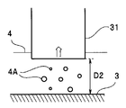
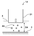
- the distal end portion 31 of the ultrasonic surgical apparatus 1 is inserted into the living body 2 and is disposed close to the tissue 3 to be treated.
- the liquid 4 exists between the distal end portion 31 and the tissue 3.
- the liquid 4 is body fluid or water such as Ringer's solution supplied from a water supply unit (not shown) of the probe 30.
- the distal end portion 31 repeats a state where the distance from the tissue 3 is D1 (FIG. 2) and a state where the distance from the tissue 3 is D2 (FIG. 3) by ultrasonic vibration.
- the amplitude of the ultrasonic vibration is (D2-D1), and changes according to the control signal level.
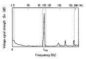
- FIG. 4 shows the frequency spectrum distribution of the voltage signal Sv of the drive signal when cavitation is not generated
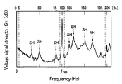
- FIG. 5 shows the frequency spectrum distribution of the voltage signal Sv when cavitation occurs. 4 and 5, the upper side indicates the frequency when the resonance frequency fres is 100%.
- the voltage signal Sv when cavitation is not generated, the voltage signal Sv does not have a large peak at frequencies other than the resonance frequency fres.
- the voltage signal Sv when cavitation occurs, the voltage signal Sv has a higher level at a frequency other than the resonance frequency fres than when no cavitation occurs. That is, when cavitation occurs, it has a subharmonic (SH) frequency peak that is a divisor, such as 1/2 or 1/4 of the resonance frequency fres, or a difference of the divisor, compared to when no cavitation occurs. Levels other than frequency are also higher than when no cavitation occurs. As the cavitation state becomes severe, the level of the voltage signal Sv is significantly different from that when no cavitation occurs, that is, the level increases.
- SH subharmonic
- the detection unit 25 can detect the cavitation state by detecting a signal excluding the vicinity of the resonance frequency fres of the voltage signal Sv of the drive signal as a cavitation level signal.
- a signal obtained by filtering the voltage signal Sv as a cavitation level signal and acquiring (integrating) only the frequency component of 95% of the resonance frequency fres from the frequency of 5% of the resonance frequency fres can be preferably used.
- the cavitation level signal may be a signal obtained by obtaining a frequency component excluding a frequency component of 5% before and after the resonance frequency fres. Further, a signal or peak intensity obtained from the subharmonic (SH) frequency component of the voltage signal Sv as the cavitation level signal can be preferably used.
- SH subharmonic
- the cavitation level signal is not limited to the voltage signal Sv but may be an impedance signal, or may be a current signal when a driving signal whose voltage is controlled by the driving unit 22 is used.
- the cavitation level signal intensity detected by the detection unit 25 varies depending on various conditions such as the type of the liquid 4, the amplitude of the ultrasonic vibration, or the state of the tissue 3, but the type of the liquid 4 and the amplitude of the ultrasonic vibration are different.
- the cavitation level signal strength represents the state of the tissue 3.
- the information acquisition part 27 can acquire the water content information of the tissue 3 based on the cavitation level signal intensity. That is, the cavitation level signal is larger when the moisture content of the tissue 3 is large than when it is small.
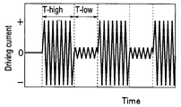
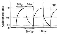
- the drive unit 22 switches the signal intensity of the drive signal supplied to the transducer 35 between high output and low output and outputs it.
- the drive signal with high output signal strength is the signal strength at which cavitation for performing treatment occurs
- the drive signal with low output signal strength is the signal strength at which cavitation does not occur
- the cavitation level signal This is the signal intensity for detecting the decay rate of.
- the high output signal supply time T-high and the low output signal supply time T-low shown in FIG. 6 are appropriately determined.
- the high output signal supply time T-high is 10 ms to 10 seconds
- T-high / (T-high + T-low) is 0.5 to 0.99. If the high output signal supply time T-high is equal to or longer than the above range, cavitation having a sufficient intensity for the detection unit 25 to detect the cavitation level signal is generated. Information can be acquired within a short time interval. Further, when T-high / (T-high + T-low) is greater than or equal to the above range, the treatment efficiency does not decrease, and when it is less than or equal to the above range, the accuracy of information acquired by the information acquisition unit 27 does not decrease. In FIG. 6, waveforms and the like are schematically shown.
- FIG. 7 corresponding to FIG. 6 shows the cavitation level signal when the diseased tissue A is treated
- FIG. 8 shows the cavitation level signal when the normal tissue B is treated.
- the cavitation level signal is a signal obtained (integrated) with a frequency component in the range of 5% to 95% of the resonance frequency fres of the drive voltage signal driven at constant current.
- the cavitation level signal increases because the cavitation bubble 4A is generated.
- the drive signal is switched to a low output, the cavitation bubble 4A is not newly generated and only collapses, so that the cavitation level signal is attenuated.
- the decay rate of the cavitation level signal is faster when the tissue A is treated (FIG. 7) than when the tissue B is treated (FIG. 8). This is because the hardness Hv-A of the tissue A is harder than the hardness Hv-B of the tissue B.
- the ultrasonic surgical apparatus 1 can acquire information on the tissue 3 based on the decay rate of the cavitation level signal.
- the ultrasonic surgical apparatus 1 may be based on the attenuation rate itself, or may use an attenuation rate.
- the attenuation rate is, for example, based on the time until the signal intensity becomes 0.1 when the cavitation level signal intensity immediately after switching the drive signal is 1.0 (10% attenuation time: T 0.1 ). Also good.
- tissue 3 is in inverse proportion to the water content of the structure
- the relationship between the attenuation rate and hardness of the cavitation level signal shown in FIG. 9 is acquired in advance and stored in the memory 24, whereby the information acquisition unit 27 is detected by the detection unit 25. Based on the cavitation level signal thus obtained, information on hardness, which is information on the tissue 3, is acquired. Further, the type discriminating unit 28 discriminates whether the tissue 3 is a normal tissue or a diseased tissue based on the hardness of the tissue 3 acquired by the information acquisition unit 27. For example, as shown in FIG. 9, when the hardness is harder than a predetermined hardness Hv-J, the type determination unit 28 determines that the tissue 3 is a lesioned tissue. The type discriminating unit 28 can also discriminate whether the tissue 3 is a muscle, a real organ, or a fat tissue.
- the ultrasonic operation apparatus 1 has been described in which the drive unit 22 switches and outputs the signal intensity of the drive signal supplied to the vibrator 35 between high output and low output.
- a drive signal may be intermittently supplied to the child 35. That is, when the vibrator 35 stops vibrating, it may take time to start the vibration again. If this time lag does not cause a problem, the drive signal may be supplied intermittently.
- the detection unit 25 uses the vibrator 35 as a sensor and the burst sound of the cavitation bubble 4A as a cavitation level signal when the ultrasonic vibrator 35 stops vibrating. , Sub-harmonic (SH) frequency component signals and the like are detected. Information on the tissue 3 is acquired from the decay rate of the cavitation level signal.
- SH Sub-harmonic
- control unit 23 controls the signal strength of the drive signal supplied by the drive unit 22 according to the information on the tissue 3 acquired by the information acquisition unit 27. That is, when the treatment for removing the lesion tissue is performed, the information acquisition unit 27 notifies the control unit 23 that the lesion tissue has been removed and the normal tissue has been exposed due to the slow decay rate of the cavitation level signal. Then, the control unit 23 controls the signal intensity of the drive signal of the high output signal supplied to the vibrator 35 to be small. For this reason, in the ultrasonic surgical apparatus 1, it is possible to prevent the normal tissue from being damaged.
- the control unit 23 may display the cavitation level signal detected by the detection unit 25 or the information on the tissue 3 acquired by the information acquisition unit 27 on the display unit 29A.
- control unit 23 controls the signal intensity of the drive signal to be small based on the information of the information acquisition unit 27, the display unit 29A and the notification unit 29B, which are also warning generation units, use characters, symbols, voice, light, vibration, or the like. A warning may be issued to the surgeon.
- the ultrasonic surgical apparatus 1 has good operability. Moreover, the ultrasonic surgical apparatus 1 has high safety.
- an ultrasonic surgical apparatus 1A according to a second embodiment of the present invention will be described. Since the ultrasonic surgical apparatus 1A according to the present embodiment is similar to the ultrasonic surgical apparatus 1 according to the first embodiment, components having the same functions are denoted by the same reference numerals and description thereof is omitted.
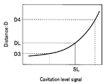
- the information acquisition unit of the ultrasonic surgical apparatus 1A according to the present embodiment acquires information on the distance D between the tissue 3 and the distal end portion 31 that is the treatment unit based on the strength of the cavitation level signal. As described with reference to FIGS. 2 and 3, the cavitation generation mechanism of the ultrasonic surgical apparatus 1A is significantly different from the cavitation generation mechanism generated by the ultrasonic waves radiated into the liquid.
- the ultrasonic surgical apparatus 1A for example, the relationship between the strength of the cavitation level signal and the distance D shown in FIG. Based on the detected cavitation level signal and the data stored in the memory 24, information on the distance from the tissue 3 to the tip is acquired.
- the control unit 23 of the ultrasonic surgical apparatus 1A reduces the signal strength of the drive signal that the drive unit 22 supplies to the vibrator 35 when the distal end portion 31 approaches the tissue 3 beyond a predetermined distance DL. To control. That is, when the cavitation level signal becomes larger than the predetermined strength SL, the information acquisition unit 27 acquires information that the distal end portion 31 exists at a distance closer to the tissue 3 than the predetermined distance DL. Based on this, the control unit 23 controls the drive unit 22. For this reason, in the ultrasonic surgical apparatus 1A, it is possible to prevent the blood vessel from being damaged. Note that the control unit 23 may increase the signal intensity again when it is detected that the tip 31 that has once approached is separated from the tissue 3 by a predetermined distance DL or more. For this reason, the ultrasonic surgical apparatus 1A has good operability.
- the ultrasonic surgical apparatus 1A based on the distance information acquired by the information acquisition unit 27, for example, by changing the number of LEDs that are turned on in the display unit 29A constituted by a plurality of LEDs, the operator can determine the distance D. It may be displayed easily. Further, when the distal end portion 31 is closer to the tissue 3 than a predetermined distance DL, a warning is given to the operator by letters, symbols, voice, light, vibration, or the like by the display unit 29A and the notification unit 29B that are also warning generation units. It may occur.
- the ultrasonic surgical apparatus 1A has good operability. Moreover, the ultrasonic surgical apparatus 1 has high safety.
- the ultrasonic surgical apparatus 1A performs the treatment inside the blood vessel, for example, arteriosclerosis in which a bulge (plaque) is generated inside the artery. It can also be used to treat the disease.
- a rotablator device can also be used for plaque removal. The rotablator device crushes the plaque by rotating at high speed a drill with a diamond at the tip of a guide wire inserted through the catheter of the endoscope device.
- the suction type ultrasonic surgical apparatus is safer than the rotablator apparatus, but it is not preferable that the distal end portion 31 is in contact with the blood vessel wall.
- the ultrasonic surgical apparatus 1A has a cavitation level signal corresponding to the state of cavitation generated in the liquid, that is, blood existing between the distal end portion 31 and the blood vessel inner wall that is the tissue 3, from the distal end portion 31 that is a treatment portion.
- the distance information to the inner wall of the blood vessel is acquired, and the control unit 23 controls the drive unit 22 according to the distance, so that the operability is excellent and the safety is also high.
- the ultrasonic surgical device 1 ⁇ / b> B is a scissors-type ultrasonic coagulation / cutting device having a device main body 20 and a handpiece 40 ⁇ / b> B connected to the device main body 20 and a cable 42.
- the ultrasonic surgical apparatus 1B further includes a high-frequency output unit 50 and a counter electrode 58 for flowing a high-frequency current from the treatment unit.
- the handpiece 40B includes the probe 30 that can apply a high-frequency current to the distal end portion 31 that is a treatment portion, and can perform a high-frequency current treatment.
- a cylindrical rod-shaped probe 30 is disposed inside the handpiece 40B, and an operation handle 43 for operating the grip portion 45 on the distal end side is disposed on the proximal end side.
- the grasping portion 45 is displaced in a direction to be pressed against the distal end portion 31 by an operation (closing operation) of grasping the operation handle 43 by the operator.
- the surgeon performs treatment on the tissue 3 (not shown in FIG. 14) grasped between the grasping portion 45 and the distal end portion 31 by frictional heat due to ultrasonic vibration.
- the high-frequency output unit 50 of the ultrasonic surgical apparatus 1 ⁇ / b> B has components similar to those of the apparatus body 20, acquires information on the tissue 3, and based on the acquired information on the tissue 3 3 adjusts the strength of the high-frequency current flowing through
- the high frequency output unit 50 includes a high frequency drive unit 52, a detection unit 55, an information acquisition unit 57, a memory 54, a control unit 53, a setting unit 56, a display unit 59A, and a notification unit 59B.
- the control unit 53 of the high frequency output unit 50 is connected to the control unit 23B of the apparatus main body unit 20 via a cable 42C.
- the control unit 53 controls the high frequency output unit 50, whereas the control unit 23B also performs overall control of the ultrasonic surgical apparatus 1B including the high frequency output unit 50.
- the high-frequency current from the high-frequency drive unit 52 is transmitted to the cable 42B via the connector 49A of the handpiece 40B connected to the socket 51 of the high-frequency output unit 50, reaches the distal end portion 31, flows through the tissue 3,
- the counter electrode 58 is reached.
- the high frequency drive unit 52 operates by setting of the setting unit 56 and control of the control unit 53.
- the detection unit 55 detects the electrical impedance of the tissue 3 between the distal end portion 31 and the counter electrode 58
- the information acquisition unit 57 is based on the impedance detected by the detection unit 55 and the data stored in the memory 54. Get information about organization 3.
- the display unit 59A and the notification unit 59B have functions similar to those of the display unit 29A and the notification unit 29B described above.
- the control unit 53 controls the power of the high-frequency current output from the high-frequency driving unit 52 based on the information acquired by the information acquisition unit 57.
- the ultrasonic surgical apparatus 1B not only has an ultrasonic treatment function and a high-frequency current treatment function of a known ultrasonic surgical apparatus or the like, but also an information acquisition function and high-frequency information on the tissue 3 being treated. And an information acquisition function using electric current.
- the information acquired by the information acquisition unit 57 of the high-frequency output unit 50 may not be the same as the information acquired by the information acquisition unit 27 of the apparatus main body unit 20.
- the information acquisition unit 57 of the high-frequency output unit 50 acquires information on the water content in the tissue 3 or type information indicating whether the tissue 3 is a muscle, a real organ, or a fat tissue.
- the information acquisition unit 57 can also acquire information such as the amount of energy administered to the tissue 3, the contact area between the tissue 3 and the distal end portion 31, and whether or not a discharge has occurred.
- the information acquisition unit 27 can also acquire information on a mechanical load such as a pressing force on the tip 31.
- the output (ultrasonic vibration / high frequency) to the probe 30 based on the stress that the tissue 3 acquired by the information acquisition unit 27 exerts on the distal end portion 31 and the contact / non-contact information with the distal end portion 31 of the tissue 3. It is also possible to control the current) and to protect the probe 30.
- the control unit 23B controls the ultrasonic vibration amplitude to be 30% of the maximum amplitude and the high frequency output to be 10 W, and the distal end portion 31 is in contact with the tissue 3. If so, the amplitude of the ultrasonic vibration is controlled to 70% of the maximum amplitude, and the high frequency output is controlled to 30 W.
- the information acquisition unit 27 can acquire a large amount of information with high accuracy when the moisture content of the tissue 3 is small, whereas the information acquisition unit 57 is a wet state when the tissue 3 has a high moisture content. In some cases, information acquisition is easy.
- FIG. 16 shows the relationship between the passage of time during treatment and the electrical resistance of the tissue 3, in other words, the moisture content.
- the tissue 3 is in “state A”, which is a state in which the water content is high and the electrical resistance is low.
- state A is a state in which the water content is high and the electrical resistance is low.
- the water in the tissue 3 is dehydrated, so the water content decreases, the electrical resistance increases, and the state becomes “state B”.
- the ultrasonic surgical apparatus 1B may acquire information on the tissue 3 using the information acquisition unit 57 in the “state A”, and may acquire information on the tissue 3 using the information acquisition unit 27 in the “state B”. preferable.
- the control unit 23 determines whether the information necessary for the treatment among the information acquisition unit 27 or the information acquisition unit 57 is easily acquired or can be acquired with high accuracy.
- At least one of the high-frequency driving unit 52 is controlled. Therefore, the ultrasonic surgical device 1B has better operability in addition to the effects of the known ultrasonic surgical device or the ultrasonic surgical device 1 or the like.
- the transducer 35 of the ultrasonic surgical apparatus to which the drive unit 22 intermittently supplies drive signals can also be used as a sensor.
- a pressing force is applied to the vibrator 35.
- information on the tissue with which the tip 31 is in contact such as hardness information or viscoelasticity information, can be obtained.
- the frequency of the transducer 35 can be swept with a small amplitude, and the impedance characteristics of the tissue can be analyzed to obtain information on the tissue on which the distal end portion 31 is performing treatment.
- an echo signal in which reverberation during driving or a burst sound of a cavitation bubble or the like is reflected back to the tissue 3 in a state where a driving current is not applied can be detected by the vibrator 35. Then, by analyzing the echo signal, the ultrasonic surgical apparatus acquires information on the boundary between the skeleton / organ and the muscle tissue or information on the acoustic impedance change surface such as the boundary between different organs as information on the tissue 3. be able to.
Abstract
超音波振動を発生する超音波振動子35と、駆動信号を超音波振動子35に供給する駆動部22と、超音波振動子35と機械的に結合され、液体4を介して生体組織3を処置する先端部31と、先端部31の超音波振動により液体4に発生するキャビテーションの状態に対応したキャビテーションレベル信号を検出する検出部25と、キャビテーションレベル信号をもとに生体組織3の情報を取得する情報取得部27と、を具備する超音波手術装置1。
Description
本発明は、生体組織を処置する超音波手術装置に関する。
超音波振動を利用して生体組織に処置を行う超音波手術装置としては、超音波凝固切開装置、超音波吸引装置、超音波砕石装置、および超音波トロッカー等がある。
超音波凝固切開装置は超音波振動するプローブで組織を把持することによって、摩擦熱を発生し凝固処理または切開処理を行う。超音波凝固切開装置は電気手術装置と比べて低温処理が可能であり、組織損傷の度合いが小さい。高周波通電が可能なプローブでは止血処置が容易である。
超音波吸引装置は超音波の組織選択性を利用し脆弱組織のみを超音波振動により、乳化し吸引するものであり、血管などの弾力性に富んだ組織を破砕せずに露出することができる。
超音波砕石装置は超音波で振動させたプローブを直接結石等に接触させて、超音波振動を衝撃に変換し結石を破壊する。
超音波振動により発生したキャビテーションにより処置を行う超音波手術装置においてはキャビテーションの状態は重要である。例えば国際公開番号WO2005/094701号パンフレットには、所定のキャビテーション状態を維持するために、キャビテーションの状態を音圧信号から検出する超音波照射方法が開示されている。
超音波手術装置においては、処理する組織の情報は重要であり、特に処置中に組織の情報を取得する超音波手術装置が求められていた。本発明は処置する生体組織の情報が取得可能な操作性の良い超音波手術装置を提供することを目的とする。
本発明の実施の形態の超音波手術装置は、超音波振動を発生する超音波振動子と、駆動信号を前記超音波振動子に供給する駆動部と、前記超音波振動子と機械的に結合され、液体を介して生体組織を処置する処置部と、前記処置部の超音波振動により前記液体に発生するキャビテーションの状態に対応したキャビテーションレベル信号を検出する検出部と、前記キャビテーションレベル信号をもとに前記生体組織の情報を取得する情報取得部と、を具備する。
<第1の実施の形態>
以下、本発明の第1の実施の形態の超音波手術装置1について図面を参照して説明する。
図1に示すように、本実施形態の超音波手術装置1は、装置本体部20と、装置本体部20のソケット21とコネクタ49を介してケーブル42により接続された超音波吸引型のハンドピース40と、装置本体部20と接続されたフットスイッチ10とを有する吸引型超音波手術装置である。
以下、本発明の第1の実施の形態の超音波手術装置1について図面を参照して説明する。
図1に示すように、本実施形態の超音波手術装置1は、装置本体部20と、装置本体部20のソケット21とコネクタ49を介してケーブル42により接続された超音波吸引型のハンドピース40と、装置本体部20と接続されたフットスイッチ10とを有する吸引型超音波手術装置である。
ハンドピース40は、超音波振動子(以下「振動子」ともいう)35と、基端部32が振動子35と機械的に結合され、振動子35が発生する振動を先端部31まで伝達する円柱棒状のプローブ30とを有する。先端部31は液体4を介して生体組織(以下「組織」ともいう)3の処置を行う処置部であり、プローブ30から着脱自在であってもよい。
超音波手術装置1の装置本体部20は、駆動部22と、制御部23と、設定部26と、検出部25と、情報取得部27と、メモリ24と、種類判別部28と、表示部29Aと、告知部29Bと、を有する。駆動部22は制御部23の制御のもと振動子35を駆動する電流制御された駆動信号を出力する。例えばCPUである制御部23は駆動部22をはじめとする超音波手術装置1の全体の制御を行う。なお超音波手術装置1では情報取得部27および種類判別部28は独立した構成要素としているが、情報取得部27と種類判別部28とは一体でもよいし、少なくともいずれかは制御部23と一体であってもよい。またメモリ24は情報取得部27または制御部23と一体であってもよい。
後述するように検出部25は先端部31の超音波振動により液体4に発生するキャビテーションの状態に対応したキャビテーションレベル信号を検出する。情報取得部27は検出部25が検出したキャビテーションレベル信号とメモリ24に記憶されているデータとをもとに組織3の情報を取得する。種類判別部28は情報取得部27が取得する組織3の情報にもとづいて組織3の種類を判別する。表示部29Aおよび告知部29Bは術者が装置本体部20の稼働状態等を認識するためのものであり、術者に警告を発生する警告発生部でもある。
すなわち、公知の国際公開番号WO2005/094701号パンフレットに開示された超音波手術装置はキャビテーションの状態を検出し所定のキャビテーション状態を維持するように制御していたのに対して、本実施の形態の超音波手術装置1はキャビテーションの状態を検出する点においては公知の超音波手術装置と類似している。しかし超音波手術装置1は駆動信号の特定周波数成分信号をもとにキャビテーションの状態を検知し、キャビテーションの状態に対応したキャビテーションレベル信号をもとに処置中の組織3の情報をリアルタイムで取得する。
駆動部22は、発振回路22Dと、乗算器22Aと、アンプ22Bと、出力回路22Cと、電流電圧検出回路22Fと、PLL(Phase-Locked Loop:位相同期回路)回路22Eと、差動アンプ22Gとを有する。発振回路22Dが発生した発振信号が乗算器22Aに入力され、乗算器22Aにより乗算された信号がアンプ22Bで増幅され、増幅された信号が出力回路22Cを介して振動子35に出力される。出力回路22Cは、例えばトランスにより構成され、1次巻線側にはアンプ22Bで増幅された駆動信号が入力され、2次巻線側から1次巻線側の駆動信号と絶縁された駆動信号を出力する。また、出力回路22Cトランスの1次巻線は、1次巻線に流れる駆動信号の電流およびその両端の電圧を検出すると共に、電流の位相および電圧の位相を検出するために電流電圧検出回路22Fと接続されている。
電流電圧検出回路22Fにより検出された電流位相信号θiと電圧位相信号θvとは、PLL回路22Eに出力される。PLL回路22Eは電流位相信号θiと電圧位相信号θvとの位相差に応じて信号レベル(信号強度)が変化する制御信号を発振回路22Dに出力する。発振回路22Dは入力された信号レベルで発振周波数が変化する、例えば電圧制御発振回路(VCO:Voltage Controlled Oscillator)である。PLL回路22Eは、電流位相信号θiと電圧位相信号θvとの位相差を小さくするように制御する発振周波数の調整信号を発振回路22Dに出力する。従って、発振回路22Dは、PLL回路22Eを用いた閉ループにより、電流位相信号θiと電圧位相信号θvとの位相差が0となるように発振周波数が自動調整される。ここで電流位相信号θiと電圧位相信号θvとの位相差が0となる状態での発振周波数は振動子35の共振周波数:fres(例えば47kHz)に対応した周波数である。すなわち、PLL回路22Eは、振動子35を共振周波数の駆動信号で駆動するように発振周波数を自動調整する。差動アンプ22Gは、駆動信号レベルが設定部26またはフットSW10により設定された出力値または後述するように制御部23が制御する値となるように制御する。
次に、図2および図3を用いて超音波手術装置1の動作について説明する。処置のとき、超音波手術装置1の先端部31は生体2内に挿入されて処置を行う組織3に近接して配置される。ここで、先端部31と組織3との間には液体4が存在している。液体4は、体液またはプローブ30の給水部(不図示)から給水されたリンゲル液等の水である。先端部31は超音波振動により組織3との距離がD1の状態(図2)と、組織3との距離がD2の状態(図3)とを繰り返す。ここで超音波振動の振幅が(D2-D1)であり、制御信号レベルに応じて変化する。先端部31と組織3との距離(間隔)が、図2の状態から図3の状態に変化すると、先端部31と組織3との間に存在する液体は負圧となり、キャビテーションが発生、すなわちキャビテーションバブル4Aが生成する。
ここで、図4はキャビテーション非発生時の駆動信号の電圧信号Svの周波数スペクトル分布を示し、図5はキャビテーション発生時の電圧信号Svの周波数スペクトル分布を示す。なお図4および図5において上辺の表示は共振周波数fresを100%としたときの周波数を示している。
図4に示すようにキャビテーション非発生時には電圧信号Svは共振周波数fres以外の周波数においては大きなピークを持たない。これに対して、図5に示すようにキャビテーション発生時には、電圧信号Svは共振周波数fres以外の周波数において、キャビテーション非発生時よりも電圧信号Svのレベルが高くなる。すなわちキャビテーション発生時には、キャビテーション非発生時よりも共振周波数fresの1/2、もしくは1/4などの約数、または約数の差分であるサブハーモニック(SH)の周波数のピークを持つと共に、サブハーモニック周波数以外のレベルも、キャビテーション非発生時よりも高くなる。そしてキャビテーションの状態が激しくなるに従い、電圧信号Svのレベルはキャビテーション非発生時との差が顕著、すなわちレベルが高くなる。
このため、検出部25は駆動信号の電圧信号Svの共振周波数fres近傍を除く信号を、キャビテーションレベル信号として検出することにより、キャビテーションの状態を検出することができる。例えばキャビテーションレベル信号として電圧信号Svをフィルタ処理して、共振周波数fresの5%の周波数から共振周波数fresの95%の周波数成分のみを取得(積分)した信号を好ましく用いることができる。またはキャビテーションレベル信号として電圧信号Svをフィルタ処理して、共振周波数fresより5%高い周波数から共振周波数fresの2次高調波の周波数(2fres)よりも5%低い周波数成分を取得した信号でもよい。またキャビテーションレベル信号として共振周波数fresの前後5%の周波数成分を除いた周波数成分を取得した信号でもよい。さらに、キャビテーションレベル信号として電圧信号Svのサブハーモニック(SH)周波数成分を取得した信号またはピーク強度も好ましく用いることができる。
なおキャビテーションレベル信号は、電圧信号Svに限られるものではなくインピーダンス信号でもよいし、駆動部22が電圧制御した駆動信号を用いる場合には電流信号でもよい。
また検知部25が検知するキャビテーションレベル信号強度は、液体4の種類、超音波振動の振幅、または組織3の状態等の種々の条件により変化するが、液体4の種類および超音波振動の振幅が同じ場合にはキャビテーションレベル信号強度は、組織3の状態を表す。このため情報取得部27はキャビテーションレベル信号強度をもとに、組織3の水分含有量の情報を取得できる。すなわちキャビテーションレベル信号は組織3の水分含有量が多い場合には少ない場合よりも大きくなる。
そして、図6に示すように、本実施の形態の超音波手術装置1においては駆動部22は振動子35に対して供給する駆動信号の信号強度を高出力と低出力とを切り替えて出力する。ここで高出力の信号強度の駆動信号は処置を行うためのキャビテーションが発生する信号強度であるのに対して、低出力の信号強度の駆動信号はキャビテーションが発生しない信号強度であり、キャビテーションレベル信号の減衰速度を検出するための信号強度である。
なお図6に示す高出力信号供給時間T-highと低出力信号供給時間T-lowとは適宜決定される。例えば高出力信号供給時間T-highは10ms~10秒であり、T-high/(T-high+T-low)は0.5~0.99である。高出力信号供給時間T-highが前記範囲以上であれば検出部25がキャビテーションレベル信号を検知するのに十分の強度のキャビテーションが発生し、前記範囲以下であれば情報取得部27が処置に必要な時間間隔内で情報を取得できる。またT-high/(T-high+T-low)が前記範囲以上では処置の効率が低下することがなく、前記範囲以下では情報取得部27が取得する情報の精度が低下しない。なお、図6においては波形等は模式的に示している。
ここで図6と対応した図7は病変組織Aを処置している場合の、図8は正常組織Bを処置している場合のキャビテーションレベル信号を示している。なお、このキャビテーションレベル信号は、定電流駆動している駆動電圧信号の共振周波数fresの5%から95%の範囲の周波数成分を取得(積分)した信号である。
図7および図8に示すように、振動子35に高出力の駆動信号が供給されるとキャビテーションバブル4Aが生成されるためキャビテーションレベル信号は増加する。しかし、駆動信号が低出力に切り替わるとキャビテーションバブル4Aは新規に生成されなくなり崩壊するだけとなるために、キャビテーションレベル信号は減衰する。ここでキャビテーションレベル信号の減衰速度は組織Aを処置している場合(図7)が組織Bを処置している場合(図8)よりも早い。これは組織Aの硬さHv-Aが組織Bの硬さHv-Bよりも硬いことに起因している。
すなわち、超音波手術装置1においてはキャビテーションレベル信号の減衰速度をもとに組織3の情報を取得することができる。ここで超音波手術装置1は減衰速度そのものをもとにしてもよいし、減衰率を用いてもよい。減衰率としては例えば駆動信号切替直後のキャビテーションレベル信号強度を1.0としたときの信号強度が0.1となるまでの時間(10%減衰時間:T0.1)等をもとにしてもよい。
例えば図9に示すように、10%減衰時間(T0.1)、すなわちキャビテーションレベル信号の減衰率は処置している組織3の硬さと相関があり、組織Aの10%減衰時間(T0.1)A-T0.1は組織BのB-T0.1より短い、すなわちキャビテーションレベル信号の減衰速度がより早い場合には、組織Aの硬さ、Hv-Aは組織BのHv-Bよりも硬い。なお組織3の硬さは組織3の水分含有量に反比例することから、硬さ情報は水分含有量情報でもある。
超音波手術装置1においては、例えば図9に示すキャビテーションレベル信号の減衰率と硬さの関係を予め取得しておき、メモリ24に記憶しておくことにより情報取得部27は検出部25が検出したキャビテーションレベル信号をもとに組織3の情報である硬さの情報を取得する。さらに種類判別部28は情報取得部27が取得した組織3の硬さをもとに、組織3が正常組織であるか病変組織であるかを判別する。例えば図9に示すように硬さが所定の硬さHv-Jよりも硬い場合に、種類判別部28は組織3が病変組織であると判別する。なお、種類判別部28は組織3が筋肉、実質臓器または脂肪組織のいずれかで種類であるか等の判別もできる。
なお以上の説明では、駆動部22は振動子35に対して供給する駆動信号の信号強度を高出力と低出力とを切り替えて出力する超音波手術装置1について説明したが、駆動部22は振動子35に対して駆動信号を間欠的に供給してもよい。すなわち振動子35は振動を停止してしまうと再度、振動を開始するために時間を要することがあるが、このタイムラグが問題とならない場合には駆動信号を間欠的に供給してもよい。
駆動信号を間欠的に供給する場合には、検出部25は超音波振動子35が振動を停止しているときに、振動子35をセンサとして用いて、キャビテーションレベル信号としてキャビテーションバブル4Aの破裂音、サブハーモニック(SH)周波数成分の信号等を検出する。そしてキャビテーションレベル信号の減衰速度から組織3の情報が取得される。
また、制御部23は情報取得部27が取得する組織3の情報に応じて、駆動部22が供給する駆動信号の信号強度を制御する。すなわち病変組織を取り除く処置を行っている場合に、情報取得部27はキャビテーションレベル信号の減衰速度が遅くなることにより病変組織が取り除かれて正常組織が露出したことを制御部23に伝達する。すると制御部23は振動子35に供給する高出力信号の駆動信号の信号強度を小さく制御する。このため超音波手術装置1においては、正常組織を傷つけることを防止することができる。また、制御部23は検出部25が検知したキャビテーションレベル信号または情報取得部27が取得した組織3の情報を、表示部29Aに表示してもよい。さらに例えば制御部23は情報取得部27の情報にもとづいて駆動信号の信号強度を小さく制御したときには警告発生部でもある表示部29Aおよび告知部29Bにより、文字、記号、音声、光または振動等により術者に警告を発生してもよい。
以上の説明のように、超音波手術装置1は操作性がよい。また超音波手術装置1は安全性が高い。
<第2の実施の形態>
次に本発明の第2の実施の形態の超音波手術装置1Aについて説明する。なお本実施の形態の超音波手術装置1Aは、第1の実施の形態の超音波手術装置1と類似しているため同じ機能の構成要素には同じ符号を付し説明は省略する。
本実施の形態の超音波手術装置1Aの情報取得部はキャビテーションレベル信号の強度をもとに、組織3と処置部である先端部31との間の距離Dの情報を取得する。図2および図3で説明したように超音波手術装置1Aのキャビテーション発生メカニズムは、液体中に放射された超音波により発生するキャビテーションの発生メカニズムとは大きく異なる。
次に本発明の第2の実施の形態の超音波手術装置1Aについて説明する。なお本実施の形態の超音波手術装置1Aは、第1の実施の形態の超音波手術装置1と類似しているため同じ機能の構成要素には同じ符号を付し説明は省略する。
本実施の形態の超音波手術装置1Aの情報取得部はキャビテーションレベル信号の強度をもとに、組織3と処置部である先端部31との間の距離Dの情報を取得する。図2および図3で説明したように超音波手術装置1Aのキャビテーション発生メカニズムは、液体中に放射された超音波により発生するキャビテーションの発生メカニズムとは大きく異なる。
このため、図10および図11に示すように先端部31から組織3である、例えば血管壁までの距離Dがより短くなると、超音波振動により液体に発生する負圧がより大きくなるため、より多くのキャビテーションバブル4Aが発生する。このため、先端部31が同じ振幅、すなわち同じ振動強度で振動していても、図12に示すように、超音波手術装置1Aにおいてはキャビテーションレベル信号の強度は距離Dに反比例する。
このため超音波手術装置1Aにおいては、例えば図12に示すキャビテーションレベル信号の強度と距離Dの関係を予め取得しておき、メモリ24に記憶しておくことにより情報取得部27は検出部25が検出したキャビテーションレベル信号とメモリ24に記憶されているデータとをもとに組織3から先端部までの距離の情報を取得する。
さらに超音波手術装置1Aの制御部23は、先端部31が予め定めた所定距離DLよりも組織3に接近した場合に駆動部22が振動子35に供給する駆動信号の信号強度が小さくなるように制御する。すなわち、キャビテーションレベル信号が所定強度SLよりも大きくなった場合には、情報取得部27は先端部31が所定距離DLよりも組織3に接近した距離に存在するという情報を取得し、その情報にもとづいて制御部23は駆動部22を制御する。このため超音波手術装置1Aにおいては、血管を傷つけることを防止することができる。なお制御部23は一度接近した先端部31が組織3から所定距離DL以上に離れたことを検知できた場合には、再び信号強度を強くしてもよい。このため、超音波手術装置1Aは操作性がよい。
また、超音波手術装置1Aでは情報取得部27が取得した距離情報にもとづいて、例えば複数個のLEDで構成した表示部29Aにおいて点灯するLEDの数を変化させて、術者に距離Dを解りやすく表示してもよい。さらに先端部31が予め定めた所定距離DLよりも組織3に接近した場合に警告発生部でもある表示部29Aおよび告知部29Bにより、文字、記号、音声、光または振動等により術者に警告を発生してもよい。
以上の説明のように、超音波手術装置1Aは操作性がよい。また超音波手術装置1は安全性が高い。
なお上記説明では血管の外部の組織3の処置を行う場合を例に説明したが、超音波手術装置1Aは、血管内部の処置、例えば動脈の内側に隆起(プラーク)が発生している動脈硬化症の治療に用いることもできる。プラーク除去にはロータブレーター装置を用いることもできる。ロータブレーター装置は、内視鏡装置のカテーテル内を挿通したガイドワイヤの先端部のダイアモンドを付けたドリルを高速で回転させることによりプラークを破砕する。吸引型超音波手術装置は、ロータブレーター装置より安全性が高いが、やはり先端部31が血管壁と接触することは好ましくない。
超音波手術装置1Aは、先端部31と組織3である血管内壁との間に存在する液体、すなわち血液に発生するキャビテーションの状態に対応したキャビテーションレベル信号の強度から処置部である先端部31から血管内壁までの距離情報を取得し、距離に応じて制御部23が駆動部22を制御するために操作性に優れ、さらに安全性も高い。
<第3の実施の形態>
次に、本発明の第3の実施の形態の超音波手術装置1Bについて説明する。なお第1の実施の形態の超音波手術装置1と類似している構成要素には同じ符号を付し説明は省略する。
図13に示すように、超音波手術装置1Bは装置本体部20と、装置本体部20とケーブル42で接続されたハンドピース40Bとを有するシザース型の超音波凝固切開装置である。さらに超音波手術装置1Bは高周波出力部50と処置部からの高周波電流を流す対極58と、をさらに有する。すなわち、ハンドピース40Bは処置部である先端部31に高周波電流を印加可能なプローブ30を有し、高周波電流処置が可能である。ハンドピース40Bの内部には円柱棒状のプローブ30が配設されており基端部側には先端部側の把持部45を操作する操作ハンドル43が配設されている。
図14に示すように、術者による操作ハンドル43を握る操作(閉操作)により、把持部45は先端部31に対して押し付けられる方向に変位する。術者は把持部45と先端部31との間で把持された組織3(図14では不図示)に対して、超音波振動による摩擦熱により処置を行う。
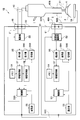
そして図15に示すように、超音波手術装置1Bの高周波出力部50は、装置本体部20と類似した構成要素を具備し組織3の情報を取得し、取得した組織3の情報にもとづいて組織3に流す高周波電流強度を調整する。
すなわち、高周波出力部50は、高周波駆動部52と、検出部55と、情報取得部57と、メモリ54と、制御部53と、設定部56と、表示部59Aと、告知部59Bとを有する。高周波出力部50の制御部53は装置本体部20の制御部23Bとケーブル42Cを介して接続されている。なお制御部53は高周波出力部50の制御を行うのに対して、制御部23Bは高周波出力部50も含めた超音波手術装置1Bの全体の制御も行う。
高周波駆動部52からの高周波電流は、高周波出力部50のソケット51と接続したハンドピース40Bのコネクタ49Aを介してケーブル42Bに伝達され、先端部31に到達し、組織3の中を流れて、対極58に至る。高周波駆動部52は設定部56の設定と制御部53の制御とにより動作する。検出部55は例えば先端部31と対極58との間の組織3の電気的インピーダンスを検出し、情報取得部57は検出部55が検出したインピーダンスとメモリ54に記憶されているデータとにもとづいて組織3の情報を取得する。表示部59Aおよび告知部59Bはすでに説明した表示部29Aおよび告知部29Bと類似した機能を有する。制御部53は情報取得部57の取得した情報にもとづき高周波駆動部52が出力する高周波電流の電力を制御する。
すなわち超音波手術装置1Bは、公知の超音波手術装置等が有する超音波による処置機能と高周波電流による処置機能とを有するだけではなく、処置している組織3の超音波による情報取得機能と高周波電流による情報取得機能とを有する。
ここで高周波出力部50の情報取得部57が取得する情報は装置本体部20の情報取得部27が取得する情報とは同じでなくともよい。例えば、高周波出力部50の情報取得部57は、組織3中の水分含有量の情報、または組織3が筋肉、実質臓器もしくは脂肪組織のいずれかで種類であるかの種類情報等を取得する。また情報取得部57は、組織3に投与したエネルギ量、組織3と先端部31との接触面積、および放電発生の有無等の情報を取得することもできる。なお情報取得部27は先端部31への押圧力等の機械的負荷の情報も取得可能である。このため情報取得部27が取得した組織3が先端部31に及ぼす応力、および組織3の先端部31との接触/非接触の情報をもとに、プローブ30への出力(超音波振動/高周波電流)を制御したり、プローブ30の保護を図ったりすること等も可能である。
例えば、制御部23Bは、先端部31が組織3と非接触の場合には、超音波振動の振幅を最大振幅の30%、高周波出力を10Wと制御し、先端部31が組織3とが接触している場合には、超音波振動の振幅を最大振幅の70%、高周波出力を30Wと制御する。
そして、情報取得部27は組織3の水分含有量が少ない場合に精度の高い多くの情報取得が可能なのに対して、情報取得部57は組織3の水分含有量が多い場合、言い換えれば湿潤状態の場合に情報取得が容易という特徴を有している。
ここで、図16は処置のときの時間経過と組織3の電気抵抗、言い換えれば水分含有量の関係を示している。図16に示すように、処置の開始時には組織3は、水分含有量が高く電気抵抗が低い状態である「状態A」である。そして処置が進むと組織3の水分は脱水されるため水分含有量が低下し電気抵抗上昇し「状態B」になる。
超音波手術装置1Bは、「状態A」においては情報取得部57を用いて組織3の情報を取得し、「状態B」においては情報取得部27を用いて組織3の情報を取得することが好ましい。すなわち制御部23は、情報取得部27または情報取得部57のうち、処置に必要な情報が取得容易または精度の高い情報が取得可能な情報取得部が取得した情報をもとに駆動部22または高周波駆動部52の少なくともいずれかを制御する。このため超音波手術装置1Bは、公知の超音波手術装置または超音波手術装置1等が有する効果に加えて、より操作性がよい。
<付記事項>
駆動部22が駆動信号を間欠的に供給する超音波手術装置の振動子35はセンサとして用いることもできる。例えば駆動電流が印加されていない状態で先端部31を組織に接触すると振動子35に押圧力が加わる。この押圧力により振動子35に生じた電気信号を解析することにより先端部31が接触した組織の情報、例えば硬さ情報または粘弾性情報等を得ることができる。さらに振動子35を小さな振幅で周波数掃引し、組織のインピーダンス特性を解析することにより先端部31が処置を行っている組織の情報を得ることもできる。なお、センサとして用いる場合および周波数掃引する場合には、処置のために振動していた振動子35の電極を短絡して制動することが好ましい。
駆動部22が駆動信号を間欠的に供給する超音波手術装置の振動子35はセンサとして用いることもできる。例えば駆動電流が印加されていない状態で先端部31を組織に接触すると振動子35に押圧力が加わる。この押圧力により振動子35に生じた電気信号を解析することにより先端部31が接触した組織の情報、例えば硬さ情報または粘弾性情報等を得ることができる。さらに振動子35を小さな振幅で周波数掃引し、組織のインピーダンス特性を解析することにより先端部31が処置を行っている組織の情報を得ることもできる。なお、センサとして用いる場合および周波数掃引する場合には、処置のために振動していた振動子35の電極を短絡して制動することが好ましい。
あるいは駆動電流が印加されていない状態で、駆動時の残響、またはキャビテーションバブルの破裂音等が組織3に反射して戻ってくるエコー信号を振動子35により検出することもできる。そしてエコー信号の解析によりし、組織3の情報として、骨格・臓器と筋組織との境界の情報、または異なった臓器の境界等の音響インピーダンスの変化面の情報等を超音波手術装置は取得することができる。
本発明は、上述した実施の形態に限定されるものではなく、本発明の要旨を変えない範囲において、種々の変更、改変等ができる。
Claims (16)
- 超音波振動を発生する超音波振動子と、
駆動信号を前記超音波振動子に供給する駆動部と、
前記超音波振動子と機械的に結合され、液体を介して生体組織を処置する処置部と、
前記処置部の超音波振動により前記液体に発生するキャビテーションの状態に対応したキャビテーションレベル信号を検出する検出部と、
前記キャビテーションレベル信号をもとに前記生体組織の情報を取得する情報取得部と、を具備することを特徴とする超音波手術装置。 - 請求項1に記載の超音波手術装置であって、
前記情報取得部が取得する前記生体組織の情報に応じて、前記駆動部が供給する前記駆動信号の信号強度を制御する制御部をさらに有する。 - 請求項2に記載の超音波手術装置であって、
前記情報取得部が取得する前記生体組織の情報に応じて、警告を発生する警告発生部をさらに有する。 - 請求項1に記載の超音波手術装置であって、
前記キャビテーションレベル信号は、前記駆動信号の電圧信号、電流信号、またはインピーダンス信号である。 - 請求項4に記載の超音波手術装置であって、
前記キャビテーションレベル信号は、前記駆動信号の駆動周波数を除く周波数の成分からなる。 - 請求項5に記載の超音波手術装置であって、
前記駆動部は前記駆動信号として、前記液体がキャビテーションを発生する高出力信号と、前記液体がキャビテーションを発生しない低出力信号と、を交互に前記超音波振動子に供給し、
前記検出部は、前記超音波振動子に前記低出力信号が供給されている間の前記キャビテーションレベル信号を検出する。 - 請求項1から請求項3のいずれか1項に記載の超音波手術装置であって、
前記駆動部は前記駆動信号を間欠的に前記超音波振動子に供給し、
前記検出部は、前記超音波振動子に前記駆動信号が供給されていない間の前記超音波振動子の出力信号をもとに前記キャビテーションレベル信号を検出する。 - 請求項7に記載の超音波手術装置であって、
前記情報取得部は、前記キャビテーションレベル信号の減衰速度にもとづいて前記生体組織の情報を取得する。 - 請求項8に記載の超音波手術装置であって、
前記情報取得部が取得する前記生体組織の情報は、前記生体組織の硬さの情報である。 - 請求項9に記載の超音波手術装置であって、
前記情報取得部は、前記キャビテーションレベル信号の減衰速度がより速い場合に前記生体組織の硬さがより硬いとする。 - 請求項8に記載の超音波手術装置であって、
前記情報取得部が取得する前記生体組織の情報にもとづいて前記生体組織の種類を判別する種類判別部をさらに有する。 - 請求項1から請求項5のいずれか1項に記載の超音波手術装置であって、
前記情報取得部が取得する前記生体組織の情報は、前記生体組織の前記処置部までの距離情報または前記生体組織の水分含有量の情報である。 - 請求項12に記載の超音波手術装置であって、
前記情報取得部は、前記キャビテーションレベル信号の強度がより大きい場合に、前記生体組織の前記処置部までの距離がより短い、または前記生体組織の水分含有量が多いとする。 - 請求項13に記載の超音波手術装置であって、
前記処置部に高周波電流を流す高周波電流駆動部と、
前記処置部からの前記高周波電流を流す対極と、
前記処置部と前記対極との間のインピーダンスにもとづいて前記生体組織の情報を取得する第2の情報取得部と、をさらに有する。 - 請求項14に記載の超音波手術装置であって、
前記生体組織の電気抵抗に応じて、前記情報取得部または前記第2の情報取得部が取得した情報をもとに前記制御部が制御を行う。 - 超音波振動を発生する超音波振動子と、
前記超音波振動子と機械的に結合され、液体を介して生体組織を処置する処置部と、
前記処置部の超音波振動により前記液体に発生するキャビテーションの状態に対応したキャビテーションレベル信号を検出する検出部と、
駆動信号として、前記液体がキャビテーションを発生する高出力信号と、前記液体がキャビテーションを発生しない低出力信号と、を交互に前記超音波振動子に供給する駆動部と、
前記超音波振動子に前記低出力信号が供給されている間に前記検出部により検出する前記キャビテーションレベル信号の減衰速度にもとづいて前記生体組織の硬さの情報を取得する情報取得部と、
前記情報取得部が取得した前記情報にもとづいて、前記高出力信号の信号強度を制御する制御部と、を具備することを特徴とする超音波手術装置。
Priority Applications (3)
| Application Number | Priority Date | Filing Date | Title |
|---|---|---|---|
| PCT/JP2009/062315 WO2011004449A1 (ja) | 2009-07-06 | 2009-07-06 | 超音波手術装置 |
| JP2011521721A JP5253576B2 (ja) | 2009-07-06 | 2009-07-06 | 超音波手術装置 |
| US13/307,966 US20120136279A1 (en) | 2009-07-06 | 2011-11-30 | Ultrasound surgical apparatus |
Applications Claiming Priority (1)
| Application Number | Priority Date | Filing Date | Title |
|---|---|---|---|
| PCT/JP2009/062315 WO2011004449A1 (ja) | 2009-07-06 | 2009-07-06 | 超音波手術装置 |
Related Child Applications (1)
| Application Number | Title | Priority Date | Filing Date |
|---|---|---|---|
| US13/307,966 Continuation US20120136279A1 (en) | 2009-07-06 | 2011-11-30 | Ultrasound surgical apparatus |
Publications (1)
| Publication Number | Publication Date |
|---|---|
| WO2011004449A1 true WO2011004449A1 (ja) | 2011-01-13 |
Family
ID=43428891
Family Applications (1)
| Application Number | Title | Priority Date | Filing Date |
|---|---|---|---|
| PCT/JP2009/062315 WO2011004449A1 (ja) | 2009-07-06 | 2009-07-06 | 超音波手術装置 |
Country Status (3)
| Country | Link |
|---|---|
| US (1) | US20120136279A1 (ja) |
| JP (1) | JP5253576B2 (ja) |
| WO (1) | WO2011004449A1 (ja) |
Cited By (2)
| Publication number | Priority date | Publication date | Assignee | Title |
|---|---|---|---|---|
| WO2013158545A1 (en) * | 2012-04-18 | 2013-10-24 | Ethicon Endo-Surgery, Inc. | Surgical instrument with tissue density sensing |
| WO2017171034A1 (ja) * | 2016-03-31 | 2017-10-05 | オリンパス株式会社 | 超音波手術器具及び超音波手術装置の処理方法 |
Families Citing this family (83)
| Publication number | Priority date | Publication date | Assignee | Title |
|---|---|---|---|---|
| US11229472B2 (en) | 2001-06-12 | 2022-01-25 | Cilag Gmbh International | Modular battery powered handheld surgical instrument with multiple magnetic position sensors |
| US8182501B2 (en) | 2004-02-27 | 2012-05-22 | Ethicon Endo-Surgery, Inc. | Ultrasonic surgical shears and method for sealing a blood vessel using same |
| US20060079877A1 (en) | 2004-10-08 | 2006-04-13 | Houser Kevin L | Feedback mechanism for use with an ultrasonic surgical instrument |
| US8057498B2 (en) | 2007-11-30 | 2011-11-15 | Ethicon Endo-Surgery, Inc. | Ultrasonic surgical instrument blades |
| US8523889B2 (en) | 2007-07-27 | 2013-09-03 | Ethicon Endo-Surgery, Inc. | Ultrasonic end effectors with increased active length |
| US8808319B2 (en) | 2007-07-27 | 2014-08-19 | Ethicon Endo-Surgery, Inc. | Surgical instruments |
| US8512365B2 (en) | 2007-07-31 | 2013-08-20 | Ethicon Endo-Surgery, Inc. | Surgical instruments |
| US9044261B2 (en) | 2007-07-31 | 2015-06-02 | Ethicon Endo-Surgery, Inc. | Temperature controlled ultrasonic surgical instruments |
| US8430898B2 (en) | 2007-07-31 | 2013-04-30 | Ethicon Endo-Surgery, Inc. | Ultrasonic surgical instruments |
| US10010339B2 (en) | 2007-11-30 | 2018-07-03 | Ethicon Llc | Ultrasonic surgical blades |
| US9089360B2 (en) | 2008-08-06 | 2015-07-28 | Ethicon Endo-Surgery, Inc. | Devices and techniques for cutting and coagulating tissue |
| US8372100B2 (en) * | 2009-06-19 | 2013-02-12 | Olympus Medical Systems Corp. | Ultrasound surgical apparatus and calibration method therefor |
| US8650728B2 (en) | 2009-06-24 | 2014-02-18 | Ethicon Endo-Surgery, Inc. | Method of assembling a transducer for a surgical instrument |
| US8663220B2 (en) | 2009-07-15 | 2014-03-04 | Ethicon Endo-Surgery, Inc. | Ultrasonic surgical instruments |
| US11090104B2 (en) | 2009-10-09 | 2021-08-17 | Cilag Gmbh International | Surgical generator for ultrasonic and electrosurgical devices |
| US8469981B2 (en) | 2010-02-11 | 2013-06-25 | Ethicon Endo-Surgery, Inc. | Rotatable cutting implement arrangements for ultrasonic surgical instruments |
| US8951272B2 (en) | 2010-02-11 | 2015-02-10 | Ethicon Endo-Surgery, Inc. | Seal arrangements for ultrasonically powered surgical instruments |
| US9439668B2 (en) | 2012-04-09 | 2016-09-13 | Ethicon Endo-Surgery, Llc | Switch arrangements for ultrasonic surgical instruments |
| US11076880B2 (en) | 2012-06-11 | 2021-08-03 | Covidien Lp | Temperature estimation and tissue detection of an ultrasonic dissector from frequency response monitoring |
| US10677764B2 (en) | 2012-06-11 | 2020-06-09 | Covidien Lp | Temperature estimation and tissue detection of an ultrasonic dissector from frequency response monitoring |
| US20140005705A1 (en) | 2012-06-29 | 2014-01-02 | Ethicon Endo-Surgery, Inc. | Surgical instruments with articulating shafts |
| US9393037B2 (en) | 2012-06-29 | 2016-07-19 | Ethicon Endo-Surgery, Llc | Surgical instruments with articulating shafts |
| US9198714B2 (en) | 2012-06-29 | 2015-12-01 | Ethicon Endo-Surgery, Inc. | Haptic feedback devices for surgical robot |
| US9408622B2 (en) | 2012-06-29 | 2016-08-09 | Ethicon Endo-Surgery, Llc | Surgical instruments with articulating shafts |
| US9226767B2 (en) | 2012-06-29 | 2016-01-05 | Ethicon Endo-Surgery, Inc. | Closed feedback control for electrosurgical device |
| US9351754B2 (en) | 2012-06-29 | 2016-05-31 | Ethicon Endo-Surgery, Llc | Ultrasonic surgical instruments with distally positioned jaw assemblies |
| US9326788B2 (en) | 2012-06-29 | 2016-05-03 | Ethicon Endo-Surgery, Llc | Lockout mechanism for use with robotic electrosurgical device |
| US9820768B2 (en) | 2012-06-29 | 2017-11-21 | Ethicon Llc | Ultrasonic surgical instruments with control mechanisms |
| US20140100459A1 (en) | 2012-10-05 | 2014-04-10 | The Regents Of The University Of Michigan | Bubble-induced color doppler feedback during histotripsy |
| US9095367B2 (en) | 2012-10-22 | 2015-08-04 | Ethicon Endo-Surgery, Inc. | Flexible harmonic waveguides/blades for surgical instruments |
| US20140135804A1 (en) | 2012-11-15 | 2014-05-15 | Ethicon Endo-Surgery, Inc. | Ultrasonic and electrosurgical devices |
| US10226273B2 (en) | 2013-03-14 | 2019-03-12 | Ethicon Llc | Mechanical fasteners for use with surgical energy devices |
| WO2015003154A1 (en) | 2013-07-03 | 2015-01-08 | Histosonics, Inc. | Articulating arm limiter for cavitational ultrasound therapy system |
| US10780298B2 (en) | 2013-08-22 | 2020-09-22 | The Regents Of The University Of Michigan | Histotripsy using very short monopolar ultrasound pulses |
| GB2521229A (en) * | 2013-12-16 | 2015-06-17 | Ethicon Endo Surgery Inc | Medical device |
| GB2521228A (en) * | 2013-12-16 | 2015-06-17 | Ethicon Endo Surgery Inc | Medical device |
| US9554854B2 (en) | 2014-03-18 | 2017-01-31 | Ethicon Endo-Surgery, Llc | Detecting short circuits in electrosurgical medical devices |
| US10092310B2 (en) | 2014-03-27 | 2018-10-09 | Ethicon Llc | Electrosurgical devices |
| US9737355B2 (en) | 2014-03-31 | 2017-08-22 | Ethicon Llc | Controlling impedance rise in electrosurgical medical devices |
| US9913680B2 (en) | 2014-04-15 | 2018-03-13 | Ethicon Llc | Software algorithms for electrosurgical instruments |
| US10285724B2 (en) | 2014-07-31 | 2019-05-14 | Ethicon Llc | Actuation mechanisms and load adjustment assemblies for surgical instruments |
| US20180001114A1 (en) * | 2014-12-15 | 2018-01-04 | Vesselon, Inc. | Automated ultrasound apparatus and method for noninvasive vessel recanalization treatment and monitoring |
| US10245095B2 (en) | 2015-02-06 | 2019-04-02 | Ethicon Llc | Electrosurgical instrument with rotation and articulation mechanisms |
| US11020140B2 (en) | 2015-06-17 | 2021-06-01 | Cilag Gmbh International | Ultrasonic surgical blade for use with ultrasonic surgical instruments |
| CN108348772B (zh) | 2015-06-24 | 2020-03-03 | 美国密歇根州立大学试剂中心 | 用于治疗脑组织的组织摧毁术治疗系统和方法 |
| US10034704B2 (en) | 2015-06-30 | 2018-07-31 | Ethicon Llc | Surgical instrument with user adaptable algorithms |
| US10357303B2 (en) | 2015-06-30 | 2019-07-23 | Ethicon Llc | Translatable outer tube for sealing using shielded lap chole dissector |
| US11051873B2 (en) | 2015-06-30 | 2021-07-06 | Cilag Gmbh International | Surgical system with user adaptable techniques employing multiple energy modalities based on tissue parameters |
| US11129669B2 (en) | 2015-06-30 | 2021-09-28 | Cilag Gmbh International | Surgical system with user adaptable techniques based on tissue type |
| US11141213B2 (en) | 2015-06-30 | 2021-10-12 | Cilag Gmbh International | Surgical instrument with user adaptable techniques |
| US11058475B2 (en) | 2015-09-30 | 2021-07-13 | Cilag Gmbh International | Method and apparatus for selecting operations of a surgical instrument based on user intention |
| US10595930B2 (en) | 2015-10-16 | 2020-03-24 | Ethicon Llc | Electrode wiping surgical device |
| US11229471B2 (en) | 2016-01-15 | 2022-01-25 | Cilag Gmbh International | Modular battery powered handheld surgical instrument with selective application of energy based on tissue characterization |
| US10537351B2 (en) | 2016-01-15 | 2020-01-21 | Ethicon Llc | Modular battery powered handheld surgical instrument with variable motor control limits |
| US11129670B2 (en) | 2016-01-15 | 2021-09-28 | Cilag Gmbh International | Modular battery powered handheld surgical instrument with selective application of energy based on button displacement, intensity, or local tissue characterization |
| US10555769B2 (en) | 2016-02-22 | 2020-02-11 | Ethicon Llc | Flexible circuits for electrosurgical instrument |
| US10456193B2 (en) | 2016-05-03 | 2019-10-29 | Ethicon Llc | Medical device with a bilateral jaw configuration for nerve stimulation |
| US10245064B2 (en) | 2016-07-12 | 2019-04-02 | Ethicon Llc | Ultrasonic surgical instrument with piezoelectric central lumen transducer |
| US10376305B2 (en) | 2016-08-05 | 2019-08-13 | Ethicon Llc | Methods and systems for advanced harmonic energy |
| USD847990S1 (en) | 2016-08-16 | 2019-05-07 | Ethicon Llc | Surgical instrument |
| US10828056B2 (en) | 2016-08-25 | 2020-11-10 | Ethicon Llc | Ultrasonic transducer to waveguide acoustic coupling, connections, and configurations |
| US10952759B2 (en) | 2016-08-25 | 2021-03-23 | Ethicon Llc | Tissue loading of a surgical instrument |
| US11266430B2 (en) | 2016-11-29 | 2022-03-08 | Cilag Gmbh International | End effector control and calibration |
| EP3886737A4 (en) | 2018-11-28 | 2022-08-24 | Histosonics, Inc. | HISTOTRIPSY SYSTEMS AND METHODS |
| US11684387B2 (en) | 2019-11-25 | 2023-06-27 | Covidien Lp | Methods and ultrasonic devices and systems for vessel sealing |
| US11660089B2 (en) | 2019-12-30 | 2023-05-30 | Cilag Gmbh International | Surgical instrument comprising a sensing system |
| CN113117262B (zh) * | 2019-12-30 | 2023-06-02 | 重庆融海超声医学工程研究中心有限公司 | 用于检测空化效应的装置、超声治疗设备 |
| US11786291B2 (en) | 2019-12-30 | 2023-10-17 | Cilag Gmbh International | Deflectable support of RF energy electrode with respect to opposing ultrasonic blade |
| US11950797B2 (en) | 2019-12-30 | 2024-04-09 | Cilag Gmbh International | Deflectable electrode with higher distal bias relative to proximal bias |
| US11944366B2 (en) | 2019-12-30 | 2024-04-02 | Cilag Gmbh International | Asymmetric segmented ultrasonic support pad for cooperative engagement with a movable RF electrode |
| US11452525B2 (en) | 2019-12-30 | 2022-09-27 | Cilag Gmbh International | Surgical instrument comprising an adjustment system |
| US20210196359A1 (en) | 2019-12-30 | 2021-07-01 | Ethicon Llc | Electrosurgical instruments with electrodes having energy focusing features |
| US11812957B2 (en) | 2019-12-30 | 2023-11-14 | Cilag Gmbh International | Surgical instrument comprising a signal interference resolution system |
| US11786294B2 (en) | 2019-12-30 | 2023-10-17 | Cilag Gmbh International | Control program for modular combination energy device |
| US11696776B2 (en) | 2019-12-30 | 2023-07-11 | Cilag Gmbh International | Articulatable surgical instrument |
| US11684412B2 (en) | 2019-12-30 | 2023-06-27 | Cilag Gmbh International | Surgical instrument with rotatable and articulatable surgical end effector |
| US20210196357A1 (en) | 2019-12-30 | 2021-07-01 | Ethicon Llc | Electrosurgical instrument with asynchronous energizing electrodes |
| US11911063B2 (en) | 2019-12-30 | 2024-02-27 | Cilag Gmbh International | Techniques for detecting ultrasonic blade to electrode contact and reducing power to ultrasonic blade |
| US11779329B2 (en) | 2019-12-30 | 2023-10-10 | Cilag Gmbh International | Surgical instrument comprising a flex circuit including a sensor system |
| US11779387B2 (en) | 2019-12-30 | 2023-10-10 | Cilag Gmbh International | Clamp arm jaw to minimize tissue sticking and improve tissue control |
| US11937863B2 (en) | 2019-12-30 | 2024-03-26 | Cilag Gmbh International | Deflectable electrode with variable compression bias along the length of the deflectable electrode |
| US11937866B2 (en) | 2019-12-30 | 2024-03-26 | Cilag Gmbh International | Method for an electrosurgical procedure |
| JP2023513012A (ja) | 2020-01-28 | 2023-03-30 | ザ リージェンツ オブ ザ ユニバーシティー オブ ミシガン | ヒストトリプシー免疫感作のためのシステムおよび方法 |
Citations (3)
| Publication number | Priority date | Publication date | Assignee | Title |
|---|---|---|---|---|
| JP2002537955A (ja) * | 1999-03-08 | 2002-11-12 | アンジオソニックス インコーポレーテッド | 二重変換機超音波溶解法および装置 |
| JP2005040222A (ja) * | 2003-07-24 | 2005-02-17 | Olympus Corp | 超音波処置装置 |
| JP2005506867A (ja) * | 2001-10-24 | 2005-03-10 | カッティング エッジ サージカル, インコーポレイテッド | 外科移植の間の骨内超音波 |
Family Cites Families (3)
| Publication number | Priority date | Publication date | Assignee | Title |
|---|---|---|---|---|
| US20040034340A1 (en) * | 1999-10-13 | 2004-02-19 | Spineco, Inc., An Ohio Corporation | Smart dissector |
| WO2005094701A1 (ja) * | 2004-03-31 | 2005-10-13 | Toudai Tlo, Ltd. | 超音波照射方法及び超音波照射装置 |
| US8512365B2 (en) * | 2007-07-31 | 2013-08-20 | Ethicon Endo-Surgery, Inc. | Surgical instruments |
-
2009
- 2009-07-06 JP JP2011521721A patent/JP5253576B2/ja not_active Expired - Fee Related
- 2009-07-06 WO PCT/JP2009/062315 patent/WO2011004449A1/ja active Application Filing
-
2011
- 2011-11-30 US US13/307,966 patent/US20120136279A1/en not_active Abandoned
Patent Citations (3)
| Publication number | Priority date | Publication date | Assignee | Title |
|---|---|---|---|---|
| JP2002537955A (ja) * | 1999-03-08 | 2002-11-12 | アンジオソニックス インコーポレーテッド | 二重変換機超音波溶解法および装置 |
| JP2005506867A (ja) * | 2001-10-24 | 2005-03-10 | カッティング エッジ サージカル, インコーポレイテッド | 外科移植の間の骨内超音波 |
| JP2005040222A (ja) * | 2003-07-24 | 2005-02-17 | Olympus Corp | 超音波処置装置 |
Cited By (6)
| Publication number | Priority date | Publication date | Assignee | Title |
|---|---|---|---|---|
| WO2013158545A1 (en) * | 2012-04-18 | 2013-10-24 | Ethicon Endo-Surgery, Inc. | Surgical instrument with tissue density sensing |
| AU2013249514B2 (en) * | 2012-04-18 | 2017-08-31 | Ethicon Endo-Surgery, Inc. | Surgical instrument with tissue density sensing |
| US9788851B2 (en) | 2012-04-18 | 2017-10-17 | Ethicon Llc | Surgical instrument with tissue density sensing |
| US10653437B2 (en) | 2012-04-18 | 2020-05-19 | Ethicon Llc | Surgical instrument with tissue density sensing |
| WO2017171034A1 (ja) * | 2016-03-31 | 2017-10-05 | オリンパス株式会社 | 超音波手術器具及び超音波手術装置の処理方法 |
| US10881425B2 (en) | 2016-03-31 | 2021-01-05 | Olympus Corporation | Ultrasonic surgical instrument and processing method for ultrasonic surgical device |
Also Published As
| Publication number | Publication date |
|---|---|
| JP5253576B2 (ja) | 2013-07-31 |
| US20120136279A1 (en) | 2012-05-31 |
| JPWO2011004449A1 (ja) | 2012-12-13 |
Similar Documents
| Publication | Publication Date | Title |
|---|---|---|
| JP5253576B2 (ja) | 超音波手術装置 | |
| JP4855541B2 (ja) | 超音波手術装置、前記超音波手術装置を具備する超音波手術システム及びキャビテーション利用方法 | |
| JP4741035B2 (ja) | 超音波手術装置、及び前記超音波手術装置のキャビテーション制御方法 | |
| US10639058B2 (en) | Ultrasonic surgical instrument with features for forming bubbles to enhance cavitation | |
| JP4950342B2 (ja) | 超音波手術装置、超音波手術システム及びキャビテーション抑制方法 | |
| US8740821B2 (en) | Medical apparatus | |
| JP5963505B2 (ja) | 超音波治療装置 | |
| WO2010146940A1 (ja) | 超音波手術装置および超音波手術装置のキャリブレーション方法 | |
| ES2831160T3 (es) | Aparato quirúrgico ultrasónico | |
| JP3699825B2 (ja) | 超音波手術装置 | |
| JP4040914B2 (ja) | 超音波手術装置 | |
| JPH03151957A (ja) | 超音波処置装置 | |
| JP2002153482A (ja) | 超音波治療装置 | |
| JP4147064B2 (ja) | 超音波処置装置 | |
| CN117241746A (zh) | 用于控制治疗性超声波介入系统的方法 | |
| JP2004141397A (ja) | 超音波砕石装置及び超音波砕石装置を備えた砕石システム |
Legal Events
| Date | Code | Title | Description |
|---|---|---|---|
| 121 | Ep: the epo has been informed by wipo that ep was designated in this application |
Ref document number: 09847054 Country of ref document: EP Kind code of ref document: A1 |
|
| WWE | Wipo information: entry into national phase |
Ref document number: 2011521721 Country of ref document: JP |
|
| NENP | Non-entry into the national phase |
Ref country code: DE |
|
| 122 | Ep: pct application non-entry in european phase |
Ref document number: 09847054 Country of ref document: EP Kind code of ref document: A1 |