WO2011004435A1 - 燃料電池システム - Google Patents
燃料電池システム Download PDFInfo
- Publication number
- WO2011004435A1 WO2011004435A1 PCT/JP2009/003198 JP2009003198W WO2011004435A1 WO 2011004435 A1 WO2011004435 A1 WO 2011004435A1 JP 2009003198 W JP2009003198 W JP 2009003198W WO 2011004435 A1 WO2011004435 A1 WO 2011004435A1
- Authority
- WO
- WIPO (PCT)
- Prior art keywords
- anode
- flow path
- gas
- fuel
- fuel cell
- Prior art date
- Legal status (The legal status is an assumption and is not a legal conclusion. Google has not performed a legal analysis and makes no representation as to the accuracy of the status listed.)
- Ceased
Links
Images



Classifications
-
- H—ELECTRICITY
- H01—ELECTRIC ELEMENTS
- H01M—PROCESSES OR MEANS, e.g. BATTERIES, FOR THE DIRECT CONVERSION OF CHEMICAL ENERGY INTO ELECTRICAL ENERGY
- H01M8/00—Fuel cells; Manufacture thereof
- H01M8/02—Details
- H01M8/0202—Collectors; Separators, e.g. bipolar separators; Interconnectors
- H01M8/023—Porous and characterised by the material
-
- H—ELECTRICITY
- H01—ELECTRIC ELEMENTS
- H01M—PROCESSES OR MEANS, e.g. BATTERIES, FOR THE DIRECT CONVERSION OF CHEMICAL ENERGY INTO ELECTRICAL ENERGY
- H01M8/00—Fuel cells; Manufacture thereof
- H01M8/02—Details
- H01M8/0202—Collectors; Separators, e.g. bipolar separators; Interconnectors
- H01M8/0258—Collectors; Separators, e.g. bipolar separators; Interconnectors characterised by the configuration of channels, e.g. by the flow field of the reactant or coolant
-
- H—ELECTRICITY
- H01—ELECTRIC ELEMENTS
- H01M—PROCESSES OR MEANS, e.g. BATTERIES, FOR THE DIRECT CONVERSION OF CHEMICAL ENERGY INTO ELECTRICAL ENERGY
- H01M8/00—Fuel cells; Manufacture thereof
- H01M8/02—Details
- H01M8/0202—Collectors; Separators, e.g. bipolar separators; Interconnectors
- H01M8/0258—Collectors; Separators, e.g. bipolar separators; Interconnectors characterised by the configuration of channels, e.g. by the flow field of the reactant or coolant
- H01M8/0263—Collectors; Separators, e.g. bipolar separators; Interconnectors characterised by the configuration of channels, e.g. by the flow field of the reactant or coolant having meandering or serpentine paths
-
- H—ELECTRICITY
- H01—ELECTRIC ELEMENTS
- H01M—PROCESSES OR MEANS, e.g. BATTERIES, FOR THE DIRECT CONVERSION OF CHEMICAL ENERGY INTO ELECTRICAL ENERGY
- H01M8/00—Fuel cells; Manufacture thereof
- H01M8/04—Auxiliary arrangements, e.g. for control of pressure or for circulation of fluids
- H01M8/04291—Arrangements for managing water in solid electrolyte fuel cell systems
-
- H—ELECTRICITY
- H01—ELECTRIC ELEMENTS
- H01M—PROCESSES OR MEANS, e.g. BATTERIES, FOR THE DIRECT CONVERSION OF CHEMICAL ENERGY INTO ELECTRICAL ENERGY
- H01M8/00—Fuel cells; Manufacture thereof
- H01M8/10—Fuel cells with solid electrolytes
- H01M8/1004—Fuel cells with solid electrolytes characterised by membrane-electrode assemblies [MEA]
-
- H—ELECTRICITY
- H01—ELECTRIC ELEMENTS
- H01M—PROCESSES OR MEANS, e.g. BATTERIES, FOR THE DIRECT CONVERSION OF CHEMICAL ENERGY INTO ELECTRICAL ENERGY
- H01M8/00—Fuel cells; Manufacture thereof
- H01M8/10—Fuel cells with solid electrolytes
- H01M8/1009—Fuel cells with solid electrolytes with one of the reactants being liquid, solid or liquid-charged
- H01M8/1011—Direct alcohol fuel cells [DAFC], e.g. direct methanol fuel cells [DMFC]
-
- H—ELECTRICITY
- H01—ELECTRIC ELEMENTS
- H01M—PROCESSES OR MEANS, e.g. BATTERIES, FOR THE DIRECT CONVERSION OF CHEMICAL ENERGY INTO ELECTRICAL ENERGY
- H01M8/00—Fuel cells; Manufacture thereof
- H01M8/24—Grouping of fuel cells, e.g. stacking of fuel cells
- H01M8/241—Grouping of fuel cells, e.g. stacking of fuel cells with solid or matrix-supported electrolytes
-
- H—ELECTRICITY
- H01—ELECTRIC ELEMENTS
- H01M—PROCESSES OR MEANS, e.g. BATTERIES, FOR THE DIRECT CONVERSION OF CHEMICAL ENERGY INTO ELECTRICAL ENERGY
- H01M8/00—Fuel cells; Manufacture thereof
- H01M8/24—Grouping of fuel cells, e.g. stacking of fuel cells
- H01M8/2465—Details of groupings of fuel cells
- H01M8/2483—Details of groupings of fuel cells characterised by internal manifolds
-
- Y—GENERAL TAGGING OF NEW TECHNOLOGICAL DEVELOPMENTS; GENERAL TAGGING OF CROSS-SECTIONAL TECHNOLOGIES SPANNING OVER SEVERAL SECTIONS OF THE IPC; TECHNICAL SUBJECTS COVERED BY FORMER USPC CROSS-REFERENCE ART COLLECTIONS [XRACs] AND DIGESTS
- Y02—TECHNOLOGIES OR APPLICATIONS FOR MITIGATION OR ADAPTATION AGAINST CLIMATE CHANGE
- Y02E—REDUCTION OF GREENHOUSE GAS [GHG] EMISSIONS, RELATED TO ENERGY GENERATION, TRANSMISSION OR DISTRIBUTION
- Y02E60/00—Enabling technologies; Technologies with a potential or indirect contribution to GHG emissions mitigation
- Y02E60/30—Hydrogen technology
- Y02E60/50—Fuel cells
Definitions
- the present invention relates to a fuel cell system that generates power by directly supplying liquid fuel to an electrode.
- Direct methanol supply type fuel cell supplies diluted methanol to the anode side and generates air by generating a chemical reaction by supplying air to the cathode side.
- DMFC Direct methanol supply type fuel cell
- a gas flow path is provided on the anode flow path plate separately from the fuel supply flow path.
- Patent Document 1 a technique in which a lyophobic porous body is disposed so as to be adjacent to the diffusion layer of the anode electrode.
- the present invention has been made to solve the above problems, and an object of the present invention is to provide a fuel cell system capable of suppressing the backflow of CO2 and droplets in the gas flow path when power generation is stopped.
- the membrane electrode assembly having the anode electrode and the cathode electrode facing each other with the electrolyte membrane interposed therebetween, the porous body in contact with the anode electrode, and the first, second, and third communicating with each other
- a fuel cell system comprising: a gas flow path having an opening of: and an anode flow path plate having a fuel flow path for supplying fuel to the anode electrode, wherein the first opening is formed in the porous body.
- a fuel cell system is provided that contacts and collects the gas generated at the anode electrode through the first opening.
- FIG. 1 is an example of a fuel cell system according to a first embodiment.
- 2A is a plan view of the second anode flow path plate
- FIG. 2B is a plan view of the first anode flow path plate. It is explanatory drawing which shows the flow of the fuel and gas at the time of the electric power generation of the fuel cell system which concerns on 1st Embodiment. It is explanatory drawing which shows the gas flow at the time of the electric power generation stop of the fuel cell system which concerns on 1st Embodiment.
- FIG. 1 shows a cross section viewed from the direction AA in FIGS. 2 (a) to 2 (b).
- a fuel cell 100a fuel cell system
- a fuel cell 100a fuel cell system
- a membrane electrode complex having an anode electrode 81 and a cathode electrode 82 facing each other with an electrolyte membrane 3 interposed therebetween.
- MEA membrane electrode complex
- lyophobic porous body 10 in contact with MEA 8
- first anode flow path plate 30a in contact with lyophobic porous body 10
- second anode flow in contact with first anode flow path plate 30a A road plate 30b and a cathode flow channel plate 40 facing the anode flow channel plate 30 via the MEA 8 are provided.
- the MEA 8 includes an electrolyte membrane 3 using a proton conductive solid polymer membrane or the like, an anode catalyst layer 1 formed by applying a catalyst to the surface of the electrolyte membrane 3, and a cathode catalyst formed in the same manner as the anode catalyst layer 1.
- An anode gas diffusion layer 4 and a cathode gas diffusion layer 5 are formed on the outside of the layer 2, the anode catalyst layer 1 and the cathode catalyst layer 2, respectively.
- the electrolyte membrane 3 is composed of a proton conductive solid polymer membrane or the like.
- the catalyst of the anode catalyst layer platinum ruthenium or the like can be used, and as the catalyst of the cathode catalyst layer 2, platinum or the like can be used.
- the anode gas diffusion layer 4 and the cathode gas diffusion layer 5 porous carbon paper or the like can be used.
- a carbon anode microporous layer 6 having a submicron pore diameter and a thickness of several tens of microns is disposed. Also good.
- the “water-repellent treatment” means that the contact angle between the porous body and water is greater than 90 °.
- a carbon cathode microporous layer 7 having pores with a submicron pore diameter and a thickness of several tens of microns may be disposed.
- the lyophobic porous body 10 carbon paper having pores with a pore diameter of several ⁇ m made of hydrophobically treated carbon fibers having a thickness of about 200 ⁇ m, a material obtained by hydrophobizing a sintered metal, and a pore diameter of several ⁇ m with electrical conductivity.
- the following porous materials having lyophobic properties can be used. “Lipophobic” means that the contact angle with water is greater than 90 °.
- the peripheral portions of the anode catalyst layer 1, the anode microporous layer 6 and the anode gas diffusion layer 4 are formed in a frame shape along the outer periphery of the anode catalyst layer 1, the anode microporous layer 6 and the anode gas diffusion layer 4.
- the seal part 9a is sealed.
- peripheral portions of the cathode catalyst layer 2, the cathode microporous layer 7 and the cathode gas diffusion layer 5 are cut out in a frame shape along the outer periphery of the cathode catalyst layer 2, the cathode microporous layer 7 and the cathode gas diffusion layer 5. It is sealed by the seal portion 9b.
- EPDM ethylene propylene diene rubber
- PPS polyphenylene sulfide resin
- PEEK polyetheretherketone resin
- the anode flow path plate 30 includes the first anode flow path plate 30a and the second anode flow path plate 30b.
- the anode flow path plate 30 may have a structure in which both are integrated.
- the first anode channel plate 30a has a fuel channel 31 and gas channels 32c, 32e formed in a groove shape on the surface in contact with the lyophobic porous body 10. Have.
- gas flow paths 32c and 32e gas flow paths 32b and 32d penetrating both surfaces of the first anode flow path plate 30a are formed.
- the fuel flow path 31 may be a serpentine flow path in which the fuel is meandered from the upstream side to the downstream side (in the direction of the arrow in the figure), but may be a parallel flow path connecting a plurality of flow paths. .
- the upstream side of the fuel flow path 31 is connected to the fuel supply port 301, and the downstream side is connected to the fuel discharge port 302.
- the upstream side of the fuel supply port 301 is connected to the fuel supply line 51a of FIG. 1 via a manifold or the like.
- the fuel supply line 51 a is provided with a fuel pump 47, and a predetermined amount of fuel is supplied into the fuel flow path 31 by the fuel pump 47.
- the downstream side of the fuel discharge port 302 is connected to the fuel discharge line 51b of FIG. 1 via a manifold or the like.
- a groove-like gas flow path 32a connected to the gas flow paths 32b and 32d is disposed on the surface of the second anode flow path plate 30b.
- the shape of the gas flow path 32a is not limited to FIG.
- the gas channel 32 has first to third openings communicated with each other.
- the gas flow path 32 faces the lyophobic porous body 10 through the first opening 33a.
- the gas flow path 32 is connected to the check valve 20 through the second opening 33b and further communicates with the outside.
- the gas flow path 32 is connected to the liquid tank connecting portion 36 through the third opening 33 c and further communicates with the liquid tank 35.
- the cathode flow path plate 40 is in contact with the cathode gas diffusion layer 5 and has an air introduction path 42 for supplying air to the cathode catalyst layer 2.
- the inlet side of the air introduction path 42 is connected to an air supply line 53 a, and air is introduced via the air pump 46.
- the outlet side of the air introduction path 42 is connected to the air discharge line 53b via a manifold or the like.
- the air introduced into the air introduction path 42 may be taken in from the outside of the fuel cell 100a via the air pump 46, or the gas recovered in the gas flow paths 32a to 32e may be reused.
- the air introduced into the air introduction path 42 may be naturally aspirated (breathing) without using the air pump 46. In this case, the cathode flow path plate 40 may be omitted.
- FIG. 3 is a conceptual diagram of the flow of fuel and the flow of exhaust gas (CO2) during power generation of the fuel cell 100a according to the first embodiment.
- fuel is supplied from the fuel supply line 51a to the fuel flow path 31 by driving the fuel pump 47.
- air is supplied from the air supply line 53 a to the air introduction path 42. Since the lyophobic porous body 10 is lyophobic, liquid fuel out of the fuel fed to the fuel flow path 31 does not permeate the hydrophobic porous body 10 and is discharged from the first opening 33a. It will never be done. However, part of the fuel is contained in the hydrophobic porous body 10 to the extent that it does not permeate.
- the liquid fuel gradually becomes a gaseous fuel as it goes deeper, passing through the pores of the hydrophobic porous body 10 and the anode gas diffusion layer 4 as shown in the direction of the dotted arrow in FIG. It reaches the electrode 81. This is because the gaseous fuel can pass through the pores in the hydrophobic porous body 10.
- CO2 is generated by the anode reaction.
- the anode microporous layer 6, the anode gas diffusion layer 4, and the lyophobic porous body 10 are lyophobic, the CO 2 gas can freely move in a continuous phase without being hindered by the fuel.
- CO2 bubbles are formed in the fuel in the fuel supply channel 31 by applying the pressure of the fuel in the fuel supply channel 31. Can be prevented.
- the CO2 passing through the lyophobic porous body 10 is discharged through the first opening 33a into the gas flow path 32 connected to the lyophobic porous body 10, as indicated by the solid arrow in FIG. Since the check valve 20 is provided, CO2 is not discharged from the second opening 33b but is discharged from the third opening 33c.
- the CO2 gas has a high concentration in the anode electrode 81 and the gas flow path 32 (32a to 32e), and the concentrations of O2 gas and N2 gas are almost zero.
- the cathode electrode 82 and the air supply flow path 42 since air is always supplied from the outside, the N2 gas concentration is high and the O2 gas concentration is high enough to cause an electrochemical reaction.
- the CO2 gas concentration is relatively lower than the anode electrode 81 side.
- concentration diffusion of CO 2 gas occurs from the anode electrode 81 to the cathode electrode 82 via the electrolyte membrane 3.
- concentration diffusion of O 2 gas or N 2 gas occurs from the cathode electrode 82 to the anode electrode 81.
- the CO2 gas permeability of the electrolyte membrane 3 is significantly higher than that of N2 gas or O2 gas, the CO2 gas concentration diffusion amount is larger than the concentration diffusion amount of O2 gas or N2 gas.
- the CO 2 gas is continuously discharged from the anode electrode 81 to the cathode electrode 82 through the electrolyte membrane 3.
- the CO 2 gas is continuously discharged from the anode electrode 81 to the cathode electrode 82 through the electrolyte membrane 3.
- about 0.1 ccm of gas permeates through the electrolyte membrane 3 to the cathode electrode 82.
- “Ccm” represents mL / min when converted to 1 atm at 25 ° C.
- CO2 generation from the anode catalyst layer 1 stops. Then, the internal pressures of the anode electrode 81 (1, 6, 4) and the gas flow paths 32a to 32e are lowered, and the gas that has flowed from the lyophobic porous body 10 toward the first opening and the third opening during power generation. The flow direction is reversed when power generation is stopped.
- the discharged liquid 38 discharged from the gas flow path 32 is sufficiently accumulated in the liquid tank 35, the discharged liquid 38 flows from the third opening along with the flow of CO2. It tends to flow in the direction of the first opening and the lyophobic porous body 10. If the opening 33a of the gas flow path 32 and the check valve 20 are not provided, the discharged liquid 38 directly enters the gas flow path 32 and reaches the lyophobic porous body 10, so that the lyophobic porous body 10 is wetted. There is.
- the fuel cell 100a When the lyophobic porous body 10 between the fuel flow path 31 and the gas flow path 32 is occupied by the liquid, the fuel is easily passed from the fuel flow path 31 to the gas flow path 32 through the lyophobic porous body 10. Since the fuel cell 100a is in a flowing state, gas-liquid separation of fuel and gas cannot be maintained inside the fuel cell 100a. That is, the fuel flow path 31 and the gas flow path 32 communicate with each other by the liquid such as the discharged liquid 38 that has entered the pores, and the lyophobic property of the lyophobic porous body 10 is destroyed. In this state, the fuel cell 100a is again in the power generation state to generate CO2 gas, or the lyophobic porous body is heated to evaporate the liquid in the lyophobic porous body. It will not be resolved unless the part is filled with gas.
- the first embodiment includes the second opening 33b and the check valve 20 provided in such a form that air flows only from the outside of the fuel cell system connected to the opening 33b into the gas flow path 32. Yes. At this time, the pressure of the gas flow path 32 becomes smaller than the atmospheric pressure by the amount of the head of the discharged liquid 38. Accordingly, the check valve 20 is opened. As a result, the exhaust liquid 38 does not enter the gas flow path 32 but air outside the fuel cell enters from the check valve 20, so that the “exhaust liquid 38 to the gas flow path 32 when power generation is stopped” described above. Intrusion "can be suppressed.
- the present invention can be used for a fuel cell system.
- Liquid tank connection 38 Exhaust liquid 40 ... Cathode flow path plate 42 . Air supply flow Path 46 ... Air pump 46 ... Liquid feed pump 51a ... Fuel supply line 51b ; Fuel discharge line 53a ... Air supply line 53b ... Air discharge line 81 ... Anode electrode 82 ... Cathode electrode
Landscapes
- Life Sciences & Earth Sciences (AREA)
- Engineering & Computer Science (AREA)
- Manufacturing & Machinery (AREA)
- Sustainable Development (AREA)
- Sustainable Energy (AREA)
- Chemical & Material Sciences (AREA)
- Chemical Kinetics & Catalysis (AREA)
- Electrochemistry (AREA)
- General Chemical & Material Sciences (AREA)
- Fuel Cell (AREA)
Abstract
電解質膜を挟んで互いに対向するアノード電極及びカソード電極を有する膜電極複合体と、前記アノード電極に接する多孔体と、互いに連通する第1、第2、及び第3の開口部を有する気体流路と、前記アノード電極に燃料を送給する燃料流路を備えるアノード流路板と、を備える燃料電池システムであって、前記第1の開口部は前記多孔体に接し、前記アノード電極で生成される気体を前記第1の開口部を介して回収することを特徴とする燃料電池システム。
Description
本発明は、液体燃料を直接電極に供給して発電する燃料電池システムに関する。
直接メタノール供給型燃料電池(DMFC)はアノード側に希釈したメタノールを供給し、カソード側に空気を供給することにより化学反応を生じさせて発電を行う。
アノード流路内とアノード出口側の流路に気液二相流を流通させずに直接型燃料電池を小型化する手法として、アノード流路板に、燃料供給流路とは別に気体流路を併設し、これらをアノード電極の拡散層に隣接するように疎液性多孔体を配置する手法が知られている(特許文献1)。
しかしながら、上述した例では、発電を停止した場合に、CO2の排出停止により気体流路とアノードの内圧が下がるため、気体回収部中のCO2が疎液性多孔体中へ逆流する場合がある。発電停止時に気体流路内や出口端に液滴が付着していた場合には、液滴が気体流路を塞ぎながら疎液性多孔体方向に逆流することにより、疎液性多孔体が濡れる場合がある。
本発明は、上記問題を解決するためになされたものであり、その目的は、発電停止時の気体流路中のCO2や液滴の逆流を抑制可能な燃料電池システムを提供することにある。
本願発明の態様によれば、電解質膜を挟んで互いに対向するアノード電極及びカソード電極を有する膜電極複合体と、前記アノード電極に接する多孔体と、互いに連通する第1、第2、及び第3の開口部を有する気体流路と、前記アノード電極に燃料を送給する燃料流路を備えるアノード流路板と、を備える燃料電池システムであって、前記第1の開口部は前記多孔体に接し、前記アノード電極で生成される気体を前記第1の開口部を介して回収することを特徴とする燃料電池システムが提供される。
本発明によれば、発電停止時の気体流路中のCO2や液滴の逆流を抑制可能な燃料電池システムが提供できる。
図面を参照して、本発明の実施の形態を説明する。以下の図面においては、同一又は類似の部分には同一又は類似の符号を付している。以下に示す実施の形態は、この発明の技術的思想を具体化するための装置や方法を例示するものであって、この発明の技術的思想は、構成部品の構造、配置等を下記のものに限定するものではない。
(第1の実施の形態)
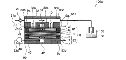
図1に、図2(a)~図2(b)のA-A方向からみた断面を示す。図1に示すように、本発明の第1の実施の形態に係る燃料電池100a(燃料電池システム)は、電解質膜3を挟んで互いに対向するアノード電極81及びカソード電極82を有する膜電極複合体(MEA)8と、MEA8に接する疎液性多孔体10と、疎液性多孔体10に接する第1のアノード流路板30aと、第1のアノード流路板30aに接する第2のアノード流路板30bと、MEA8を介してアノード流路板30に対向するカソード流路板40と、を備える。
図1に、図2(a)~図2(b)のA-A方向からみた断面を示す。図1に示すように、本発明の第1の実施の形態に係る燃料電池100a(燃料電池システム)は、電解質膜3を挟んで互いに対向するアノード電極81及びカソード電極82を有する膜電極複合体(MEA)8と、MEA8に接する疎液性多孔体10と、疎液性多孔体10に接する第1のアノード流路板30aと、第1のアノード流路板30aに接する第2のアノード流路板30bと、MEA8を介してアノード流路板30に対向するカソード流路板40と、を備える。
MEA8は、プロトン導電性の固体高分子膜等を用いた電解質膜3、電解質膜3の表面に触媒を塗布して形成されたアノード触媒層1及びアノード触媒層1と同様に形成されたカソード触媒層2、アノード触媒層1及びカソード触媒層2の外側にそれぞれ形成されたアノードガス拡散層4及びカソードガス拡散層5を備える。
電解質膜3は、プロトン導電性の固体高分子膜等から構成されている。アノード触媒層1の触媒としては白金ルテニウム等を、カソード触媒層2の触媒としては白金等を利用することができる。アノードガス拡散層4、カソードガス拡散層5としては、多孔質のカーボンペーパー等を用いることができる。
アノード触媒層1とアノードガス拡散層4との間には、撥水処理した、サブミクロンの孔径の細孔を有し、数十ミクロン厚みを有するカーボン製のアノードマイクロポーラス層6が配置されてもよい。なお、「撥水処理」とは、多孔体と水との接触角が90°より大きくなるように処理することをいう。カソード触媒層2とカソードガス拡散層5との間には、サブミクロンの孔径の細孔を有し、数十ミクロン厚みを有するカーボン製のカソードマイクロポーラス層7が配置されていてもよい。
疎液性多孔体10としては、厚み約200μmの疎水処理されたカーボン繊維よりなる孔径数μmの細孔を有するカーボンペーパー、燒結金属を疎水化処理した材料や、電気伝導性を有する孔径数μm以下の多孔体で疎液性を有する材料を用いることができる。なお、「疎液性」とは、水との接触角が90°よりも大きい性質を意味する。疎液性多孔体10を配置することにより、MEA8を任意の方向に傾けたとしてもCO2と燃料とを容易に気液分離できる。
アノード触媒層1、アノードマイクロポーラス層6及びアノードガス拡散層4の周縁部は、アノード触媒層1、アノードマイクロポーラス層6及びアノードガス拡散層4の外周に沿って額縁状に形成された第1のシール部9aによりシールされている。
カソード触媒層2、カソードマイクロポーラス層7及びカソードガス拡散層5の周縁部は、カソード触媒層2、カソードマイクロポーラス層7及びカソードガス拡散層5の外周に沿って額縁状に切り抜いた第2のシール部9bによりシールされている。
シール部9a、9bとしては、エチレンプロピレンジエンゴム(EPDM)を用いるのが好ましい。EPDMゴムは、酸素や窒素を透過する一方でCO2を透過しにくい性質を有しており、高温・高圧条件にも耐性を有する材料であるためである。EPDMの他にも、ポリフェニレンサルファイド樹脂(PPS)、ポリエーテルエーテルケトン樹脂(PEEK)等も、高温・高圧耐性を有し、水素を透過しにくく、CO2を透過しにくい性質を持つことから、シール部9a、9bの材料として、好適に用いることができる。
アノード流路板30は、図1に示すように、第1アノード流路板30a及び第2アノード流路板30bを備えているが、両者を一体化させた構造であっても構わない。図2(b)に示すように、第1アノード流路板30aには、疎液性多孔体10と接する表面上に、溝状に形成された燃料流路31及び気体流路32c、32eを有する。気体流路32c、32eには、第1アノード流路板30aの両面を貫通する気体流路32b、32dが形成されている。
燃料流路31は、例えば燃料を上流側から下流側(図中の矢印の向き)に向かって蛇行させたサーペンタイン流路が採用できるが、複数の流路を繋げた並行流路としても構わない。図2(b)に示すように、燃料流路31の上流側は、燃料供給口301に接続され、下流側は燃料排出口302に接続されている。燃料供給口301の上流側は、マニホールド等を介して図1の燃料供給ライン51aに接続されている。燃料供給ライン51aには燃料ポンプ47が設けられており、燃料ポンプ47によって所定量の燃料が燃料流路31中に供給される。燃料排出口302の下流側は、マニホールド等を介して図1の燃料排出ライン51bに接続されている。
図2(a)に示すように、第2アノード流路板30bの表面には、気体流路32b、32dに接続される溝状の気体流路32aが配置されている。気体流路32aの形状は図2(a)に限定されない。
気体流路32は互いに連通した第1乃至第3の開口部を有する。気体流路32は第1の開口部33aを介して疎液性多孔体10に対向する。気体流路32は第2の開口部33bを介して逆止弁20に連結し、さらに外部に通じている。気体流路32は第3の開口部33cを介して液タンク接続部36に連結し、さらに液タンク35に通じている。
カソード流路板40は、図1に示すように、カソードガス拡散層5と接し、カソード触媒層2に空気を送給するための空気導入路42を有している。空気導入路42の入口側は空気供給ライン53aに接続されており、空気ポンプ46を介して空気が導入される。空気導入路42の出口側はマニホールド等を介して空気排出ライン53bに接続されている。空気導入路42に導入される空気は、空気ポンプ46を介して燃料電池100aの外部から取り込んでも構わないし、気体流路32a~32eで回収された気体を再利用しても構わない。空気導入路42に導入される空気は、空気ポンプ46を用いずに自然吸気(ブリージング)にしても構わない。この場合、カソード流路板40は省略してもよい。
図3は、第1の実施の形態に係る燃料電池100aの発電時の燃料の流れ及び排出ガス(CO2)の流れの概念図である。
発電時は、燃料ポンプ47を駆動させることにより、燃料供給ライン51aから燃料流路31へ燃料が供給される。空気ポンプ46を駆動させることにより、空気供給ライン53aから空気導入路42へ空気が供給される。疎液性多孔体10が疎液性であるため、燃料流路31に送給された燃料のうち、液体状の燃料は疎水性多孔体10を透過しないため、第1の開口部33aから排出されることはない。ただし、透過しない程度に燃料の一部は疎水性多孔体10に含まれている。一方、液体状の燃料は少しずつ深奥部に行くに従い気体状の燃料となりつつ疎水性多孔体10やアノードガス拡散層4の細孔を通り、図3の点線矢印の方向に示すように、アノード電極81へ到達する。気体状の燃料は疎水性多孔体10の中の細孔を通ることができるからである。
アノード触媒層1では、アノード反応によりCO2が生成する。ここでアノードマイクロポーラス層6、 アノードガス拡散層4, 疎液性多孔体10は疎液性であることからCO2ガスは燃料に妨げられることなく連続相を成して自由に移動できる。また疎液性多孔体10と燃料供給流路31との界面では、燃料供給流路31中の燃料の圧力を掛けることで燃料供給流路31中の燃料中にCO2の気泡が形成されるのを妨げることが出来る。
疎液性多孔体10中を通過するCO2は、図3の実線矢印で示すように、疎液性多孔体10に接続された気体流路32に、第1の開口部33aを通じて排出されるが、上記の逆止弁20があるため、CO2は第2の開口部33bからは排出されず、第3の開口部33cから排出される。
また、水蒸気や、時として気化した燃料の一部は気体流路32に流れ、その一部は凝縮し、第3の開口部33cに連結した液タンク35に排出液38として蓄積される。
このようにして燃料供給流路31内には、気体が流れ込むことが殆どないことから、燃料供給流路31内部に気液二相流が形成されることによる体積膨張による流速の高速化や、メニスカス形成による流体の圧力損失が抑制され、アノード(燃料流路31)の圧力損失を大幅に小さくできる。
発電時は、アノード電極81と気体流路32(32a~32e)においてCO2ガスが高濃度となり、O2ガスやN2ガスの濃度はほぼゼロとなる。一方で、カソード電極82と空気供給流路42においては、空気が外部から常に供給されることからN2ガス濃度は高く、また電気化学反応が生じるのに十分なほどO2ガス濃度は高く、それぞれ維持されており、相対的にアノード電極81側よりCO2ガス濃度は低い状態にある。このように、アノード電極81側とカソード電極82側とでは、それぞれの気体に関し濃度差があるため、電解質膜3を介してアノード電極81からカソード電極82へCO2ガスの濃度拡散が生じる。一方、カソード電極82からアノード電極81へO2ガスやN2ガスの濃度拡散が生じる。
ところが、電解質膜3のCO2ガス透過性は、N2ガスやO2ガスより著しく高いことから、CO2ガス濃度拡散量は、O2ガスやN2ガスの濃度拡散量より多くなる。結果として、電解質膜3を介してCO2ガスがアノード電極81からカソード電極82へ継続的に排出され続けることになる。例えば、燃料電池発電時にアノード触媒層1からCO2が2.5~2.8ccm発生する場合は、電解質膜3を通して約0.1ccmのガスがカソード電極82に透過する。なお、「ccm」は、25℃1気圧に換算した時のmL/分を表す。
発電を停止させると、アノード触媒層1からのCO2発生が止まる。するとアノード電極81(1、6、4)と気体流路32a~32eの内圧が下がり、発電時には疎液性多孔体10から第1の開口部、そして第3の開口部へと向かっていたガスの流れ方向が、発電停止時には逆になる。
その結果、図4に示すように、もし気体流路32から排出された排出液38が十分に液タンク35にたまっていると、排出液38がCO2の流れに伴い、第3の開口部から第1の開口部、そして疎液性多孔体10の方向に流れようとする。もし気体流路32の開口33aと逆止弁20がない場合は、排出液38はそのまま気体流路32に侵入し、疎液性多孔体10まで達するため、疎液性多孔体10を濡らす場合がある。
燃料流路31と気体流路32との間の疎液性多孔体10が液体で占められると、燃料が燃料流路31から気体流路32まで疎液性多孔体10中を介して容易に流れる状態となるため、燃料電池100a内部で、燃料とガスの気液分離が維持できなくなる。すなわち、細孔内部に侵入した排出液38などの液体によって燃料流路31と気体流路32が連通し、疎液性多孔体10の疎液性が破壊された状態となる。この状態は、再び燃料電池100aを発電状態にしてCO2ガスを発生させるか、疎液性多孔体を加熱して疎液性多孔体内の液体を蒸発させることで、疎液性多孔体10の大部分をガスで満たさないと解消されない。
しかし、第1の実施の形態においては、第2の開口部33bと、これに連結した燃料電池システムの外部から気体流路32内へのみ空気が流れる形態に備えた逆止弁20を備えている。このとき排出液38の水頭の分、気体流路32の圧力は大気圧より小さくなる。従って逆止弁20が開く。すると排出液38が気体流路32に侵入するのではなく、逆止弁20から燃料電池の外部の空気が侵入するので、上記の「発電を止めたときの気体流路32への排出液38の侵入」が抑制できる。液タンク35に排出液38が十分たまっておらず、気体流路32の途中に液体が凝縮して気体流路32を閉塞した場合においても同様のことが言える。すなわち、液体が閉塞することによる気体流路32の圧力損失増加の分、気体流路32の圧力は大気圧より小さくなり、逆止弁20が開くためである。この場合も上記の「発電を止めたときの気体流路32への排出液38の侵入」が抑制できる。
なお、図1、図2(a)~(b)に示した燃料供給流路31及び気体流路32の構成及び配置の説明は一例であり、他にも様々な構成が採用できることは勿論である。第1の実施の形態においては、メタノール水溶液等の液体を利用した燃料電池の例を説明しているが、メタノール以外のアルコールや、炭化水素、エーテル等でも構わない。
このように、本発明は上記の実施の形態によって記載したが、この開示の一部をなす論述及び図面はこの発明を限定するものであると理解すべきではない。この開示から当業者には様々な代替実施の形態、実施例及び運用技術が可能である。本発明は、この開示から妥当な特許請求の範囲の発明特定事項によって表されるものであり、実施段階においては、その要旨を逸脱しない範囲で変形して具体化できる。
本発明は燃料電池システムに利用することができる。
1…アノード触媒層
2…カソード触媒層
3…電解質膜
4…アノードガス拡散層
5…カソードガス拡散層
6…アノードマイクロポーラス層
7…カソードマイクロポーラス層
8…膜電極複合体(MEA)
9a、9b…シール部
10…疎液性多孔体
20…逆止弁
30、30a、30b…アノード流路板
303…気体流路入口端
304…気体流路出口端
31…燃料流路
32a~32e…気体流路
33a…第1の開口部
33b…第2の開口部
33c…第3の開口部
35…液タンク
36…液タンク接続部
38…排出液
40…カソード流路板
42…空気供給流路
46…空気ポンプ
46…送液ポンプ
51a…燃料供給ライン
51b…燃料排出ライン
53a…空気供給ライン
53b…空気排出ライン
81…アノード電極
82…カソード電極
2…カソード触媒層
3…電解質膜
4…アノードガス拡散層
5…カソードガス拡散層
6…アノードマイクロポーラス層
7…カソードマイクロポーラス層
8…膜電極複合体(MEA)
9a、9b…シール部
10…疎液性多孔体
20…逆止弁
30、30a、30b…アノード流路板
303…気体流路入口端
304…気体流路出口端
31…燃料流路
32a~32e…気体流路
33a…第1の開口部
33b…第2の開口部
33c…第3の開口部
35…液タンク
36…液タンク接続部
38…排出液
40…カソード流路板
42…空気供給流路
46…空気ポンプ
46…送液ポンプ
51a…燃料供給ライン
51b…燃料排出ライン
53a…空気供給ライン
53b…空気排出ライン
81…アノード電極
82…カソード電極
Claims (5)
- 電解質膜を挟んで互いに対向するアノード電極及びカソード電極を有する膜電極複合体と、
前記アノード電極に接する多孔体と、
互いに連通する第1、第2、及び第3の開口部を有する気体流路と、
前記アノード電極に燃料を送給する燃料流路を備えるアノード流路板と、
を備える燃料電池システムであって、
前記第1の開口部は前記多孔体に接し、前記アノード電極で生成される気体を前記第1の開口部を介して回収することを特徴とする燃料電池システム。 - 前記燃料電池システムの外部から前記第2の開口部を介して空気を吸い込む構造を備えることを特徴とする請求項1に記載の燃料電池システム。
- 前記吸い込む構造として逆止弁を有することを特徴とする、請求項2に記載の燃料電池システム。
- 前記逆止弁は外部から内部へのみ空気が流れることを可能とすることを特徴とする請求項3に記載の燃料電池システム。
- 前記燃料電池システムの内部から前記第3の開口部を介して前記気体を外部に排出する構造を備えることを特徴とする請求項3に記載の燃料電池システム。
Priority Applications (1)
| Application Number | Priority Date | Filing Date | Title |
|---|---|---|---|
| PCT/JP2009/003198 WO2011004435A1 (ja) | 2009-07-09 | 2009-07-09 | 燃料電池システム |
Applications Claiming Priority (1)
| Application Number | Priority Date | Filing Date | Title |
|---|---|---|---|
| PCT/JP2009/003198 WO2011004435A1 (ja) | 2009-07-09 | 2009-07-09 | 燃料電池システム |
Publications (1)
| Publication Number | Publication Date |
|---|---|
| WO2011004435A1 true WO2011004435A1 (ja) | 2011-01-13 |
Family
ID=43428877
Family Applications (1)
| Application Number | Title | Priority Date | Filing Date |
|---|---|---|---|
| PCT/JP2009/003198 Ceased WO2011004435A1 (ja) | 2009-07-09 | 2009-07-09 | 燃料電池システム |
Country Status (1)
| Country | Link |
|---|---|
| WO (1) | WO2011004435A1 (ja) |
Citations (7)
| Publication number | Priority date | Publication date | Assignee | Title |
|---|---|---|---|---|
| JPH02168564A (ja) * | 1988-12-21 | 1990-06-28 | Nippon Soken Inc | 燃料電池 |
| JP2006294603A (ja) * | 2005-03-18 | 2006-10-26 | Matsushita Electric Ind Co Ltd | 直接型燃料電池 |
| JP2008270146A (ja) * | 2007-03-26 | 2008-11-06 | Toshiba Corp | 燃料電池 |
| JP2009037919A (ja) * | 2007-08-02 | 2009-02-19 | Sharp Corp | 燃料電池およびその製造方法、ならびに燃料電池スタック |
| JP2009245851A (ja) * | 2008-03-31 | 2009-10-22 | Toshiba Corp | 燃料電池システム |
| JP2009245848A (ja) * | 2008-03-31 | 2009-10-22 | Toshiba Corp | 燃料電池システム |
| JP2009277447A (ja) * | 2008-05-13 | 2009-11-26 | Sharp Corp | 燃料電池および燃料電池スタック |
-
2009
- 2009-07-09 WO PCT/JP2009/003198 patent/WO2011004435A1/ja not_active Ceased
Patent Citations (7)
| Publication number | Priority date | Publication date | Assignee | Title |
|---|---|---|---|---|
| JPH02168564A (ja) * | 1988-12-21 | 1990-06-28 | Nippon Soken Inc | 燃料電池 |
| JP2006294603A (ja) * | 2005-03-18 | 2006-10-26 | Matsushita Electric Ind Co Ltd | 直接型燃料電池 |
| JP2008270146A (ja) * | 2007-03-26 | 2008-11-06 | Toshiba Corp | 燃料電池 |
| JP2009037919A (ja) * | 2007-08-02 | 2009-02-19 | Sharp Corp | 燃料電池およびその製造方法、ならびに燃料電池スタック |
| JP2009245851A (ja) * | 2008-03-31 | 2009-10-22 | Toshiba Corp | 燃料電池システム |
| JP2009245848A (ja) * | 2008-03-31 | 2009-10-22 | Toshiba Corp | 燃料電池システム |
| JP2009277447A (ja) * | 2008-05-13 | 2009-11-26 | Sharp Corp | 燃料電池および燃料電池スタック |
Similar Documents
| Publication | Publication Date | Title |
|---|---|---|
| US7709130B2 (en) | Fuel cell | |
| JP5184795B2 (ja) | 燃料電池、燃料電池システムおよび電子機器 | |
| JP4575329B2 (ja) | 気液分離装置 | |
| JP2008270146A (ja) | 燃料電池 | |
| JP2009080965A (ja) | 燃料電池 | |
| JP2008243491A (ja) | 燃料電池 | |
| CA2575779A1 (en) | Fuel cell with electroosmotic pump | |
| KR101096303B1 (ko) | 연료 전지 발전 시스템 및 그 제조 방법 | |
| JP2009277447A (ja) | 燃料電池および燃料電池スタック | |
| US20080241618A1 (en) | Fuel cell | |
| JP4563344B2 (ja) | 直接液体燃料電池の気液分離装置 | |
| US20090246565A1 (en) | Fuel cell system and fuel cell control method | |
| KR20090019980A (ko) | 연료전지시스템의 배기가스 내 수소 회수 및 재활용 장치 | |
| CN101606254A (zh) | 燃料电池 | |
| TW200822432A (en) | Connecting structure of a liquid sending apparatus, fuel-cell type electricity generating apparatus, and electronic device | |
| JP2009245851A (ja) | 燃料電池システム | |
| JP2007273167A (ja) | 燃料電池 | |
| JP4453426B2 (ja) | 燃料電池 | |
| US20090081504A1 (en) | Fuel cell | |
| JP7504395B2 (ja) | 燃料電池 | |
| JP2008186800A (ja) | 気液分離器およびこれを備えた燃料電池装置 | |
| CN223983735U (zh) | 用于气体电解装置的双极板以及气体电解装置 | |
| JP2010225453A (ja) | 燃料電池スタック | |
| JP4886280B2 (ja) | 反応ガス用加湿装置 | |
| JP2010192393A (ja) | 燃料電池 |
Legal Events
| Date | Code | Title | Description |
|---|---|---|---|
| 121 | Ep: the epo has been informed by wipo that ep was designated in this application |
Ref document number: 09847040 Country of ref document: EP Kind code of ref document: A1 |
|
| NENP | Non-entry into the national phase |
Ref country code: DE |
|
| 122 | Ep: pct application non-entry in european phase |
Ref document number: 09847040 Country of ref document: EP Kind code of ref document: A1 |
|
| NENP | Non-entry into the national phase |
Ref country code: JP |