WO2010146870A1 - 酸素濃縮装置とその起動制御方法 - Google Patents
酸素濃縮装置とその起動制御方法 Download PDFInfo
- Publication number
- WO2010146870A1 WO2010146870A1 PCT/JP2010/004063 JP2010004063W WO2010146870A1 WO 2010146870 A1 WO2010146870 A1 WO 2010146870A1 JP 2010004063 W JP2010004063 W JP 2010004063W WO 2010146870 A1 WO2010146870 A1 WO 2010146870A1
- Authority
- WO
- WIPO (PCT)
- Prior art keywords
- flow rate
- oxygen
- compressed air
- rotational speed
- oxygen flow
- Prior art date
- Legal status (The legal status is an assumption and is not a legal conclusion. Google has not performed a legal analysis and makes no representation as to the accuracy of the status listed.)
- Ceased
Links
Images








Classifications
-
- A—HUMAN NECESSITIES
- A61—MEDICAL OR VETERINARY SCIENCE; HYGIENE
- A61M—DEVICES FOR INTRODUCING MEDIA INTO, OR ONTO, THE BODY; DEVICES FOR TRANSDUCING BODY MEDIA OR FOR TAKING MEDIA FROM THE BODY; DEVICES FOR PRODUCING OR ENDING SLEEP OR STUPOR
- A61M16/00—Devices for influencing the respiratory system of patients by gas treatment, e.g. ventilators; Tracheal tubes
- A61M16/10—Preparation of respiratory gases or vapours
-
- A—HUMAN NECESSITIES
- A61—MEDICAL OR VETERINARY SCIENCE; HYGIENE
- A61M—DEVICES FOR INTRODUCING MEDIA INTO, OR ONTO, THE BODY; DEVICES FOR TRANSDUCING BODY MEDIA OR FOR TAKING MEDIA FROM THE BODY; DEVICES FOR PRODUCING OR ENDING SLEEP OR STUPOR
- A61M16/00—Devices for influencing the respiratory system of patients by gas treatment, e.g. ventilators; Tracheal tubes
- A61M16/06—Respiratory or anaesthetic masks
- A61M16/0666—Nasal cannulas or tubing
- A61M16/0672—Nasal cannula assemblies for oxygen therapy
- A61M16/0677—Gas-saving devices therefor
-
- A—HUMAN NECESSITIES
- A61—MEDICAL OR VETERINARY SCIENCE; HYGIENE
- A61M—DEVICES FOR INTRODUCING MEDIA INTO, OR ONTO, THE BODY; DEVICES FOR TRANSDUCING BODY MEDIA OR FOR TAKING MEDIA FROM THE BODY; DEVICES FOR PRODUCING OR ENDING SLEEP OR STUPOR
- A61M16/00—Devices for influencing the respiratory system of patients by gas treatment, e.g. ventilators; Tracheal tubes
- A61M16/10—Preparation of respiratory gases or vapours
- A61M16/1005—Preparation of respiratory gases or vapours with O2 features or with parameter measurement
- A61M16/101—Preparation of respiratory gases or vapours with O2 features or with parameter measurement using an oxygen concentrator
-
- B—PERFORMING OPERATIONS; TRANSPORTING
- B01—PHYSICAL OR CHEMICAL PROCESSES OR APPARATUS IN GENERAL
- B01D—SEPARATION
- B01D53/00—Separation of gases or vapours; Recovering vapours of volatile solvents from gases; Chemical or biological purification of waste gases, e.g. engine exhaust gases, smoke, fumes, flue gases, aerosols
- B01D53/02—Separation of gases or vapours; Recovering vapours of volatile solvents from gases; Chemical or biological purification of waste gases, e.g. engine exhaust gases, smoke, fumes, flue gases, aerosols by adsorption, e.g. preparative gas chromatography
- B01D53/06—Separation of gases or vapours; Recovering vapours of volatile solvents from gases; Chemical or biological purification of waste gases, e.g. engine exhaust gases, smoke, fumes, flue gases, aerosols by adsorption, e.g. preparative gas chromatography with moving adsorbents, e.g. rotating beds
-
- C—CHEMISTRY; METALLURGY
- C01—INORGANIC CHEMISTRY
- C01B—NON-METALLIC ELEMENTS; COMPOUNDS THEREOF; METALLOIDS OR COMPOUNDS THEREOF NOT COVERED BY SUBCLASS C01C
- C01B13/00—Oxygen; Ozone; Oxides or hydroxides in general
- C01B13/02—Preparation of oxygen
- C01B13/0229—Purification or separation processes
- C01B13/0248—Physical processing only
- C01B13/0259—Physical processing only by adsorption on solids
-
- B—PERFORMING OPERATIONS; TRANSPORTING
- B01—PHYSICAL OR CHEMICAL PROCESSES OR APPARATUS IN GENERAL
- B01D—SEPARATION
- B01D2253/00—Adsorbents used in seperation treatment of gases and vapours
- B01D2253/10—Inorganic adsorbents
- B01D2253/106—Silica or silicates
- B01D2253/108—Zeolites
-
- B—PERFORMING OPERATIONS; TRANSPORTING
- B01—PHYSICAL OR CHEMICAL PROCESSES OR APPARATUS IN GENERAL
- B01D—SEPARATION
- B01D2256/00—Main component in the product gas stream after treatment
- B01D2256/12—Oxygen
-
- B—PERFORMING OPERATIONS; TRANSPORTING
- B01—PHYSICAL OR CHEMICAL PROCESSES OR APPARATUS IN GENERAL
- B01D—SEPARATION
- B01D2257/00—Components to be removed
- B01D2257/10—Single element gases other than halogens
- B01D2257/102—Nitrogen
-
- B—PERFORMING OPERATIONS; TRANSPORTING
- B01—PHYSICAL OR CHEMICAL PROCESSES OR APPARATUS IN GENERAL
- B01D—SEPARATION
- B01D2258/00—Sources of waste gases
-
- B—PERFORMING OPERATIONS; TRANSPORTING
- B01—PHYSICAL OR CHEMICAL PROCESSES OR APPARATUS IN GENERAL
- B01D—SEPARATION
- B01D2259/00—Type of treatment
- B01D2259/45—Gas separation or purification devices adapted for specific applications
- B01D2259/4533—Gas separation or purification devices adapted for specific applications for medical purposes
-
- C—CHEMISTRY; METALLURGY
- C01—INORGANIC CHEMISTRY
- C01B—NON-METALLIC ELEMENTS; COMPOUNDS THEREOF; METALLOIDS OR COMPOUNDS THEREOF NOT COVERED BY SUBCLASS C01C
- C01B2210/00—Purification or separation of specific gases
- C01B2210/0043—Impurity removed
- C01B2210/0046—Nitrogen
Definitions
- the present invention relates to an improvement of an oxygen concentrator that separates and generates oxygen from the air.
- Patent Document 1 discloses a relatively compact oxygen concentrator that allows a patient to ingest oxygen generated by adsorbing nitrogen into an adsorbent cylinder and adsorbing nitrogen to the adsorbent in the adsorption cylinder. It has been known.
- Patent document 1 is based on the proposal by this application, but this apparatus implement
- FIG. 13 and FIG. 14 the numbers on the horizontal axis of these graphs correspond to the 16 products of the oxygen concentrator, respectively, and the vertical axis activates each of these devices to indicate oxygen. It shows the pressurization time of the compressor that is generated and stored in the buffer tank to reach 90 kPa.
- FIG. 14 shows the results of an experiment assuming a relatively low room temperature environment such as winter. Specifically, it was stored at 0 degrees for 24 hours, and when it was set to 1 L (liter) as a relatively low set flow rate (oxygen flow rate) as in FIG. 13, it was about 90 kPa for all 16 units. It takes a long time to reach, and in severe cases it takes nearly 60 seconds, and the required time has increased almost five times.
- FIG. 15 shows a shallow cup-shaped piston cup that moves in a cylinder in the compressor.
- the cylinder and the piston are in contact with each other with almost no gap so that the sealing performance is good.
- the outer diameter of the piston cup contracts to form a gap, and the efficiency of generating compressed air due to leakage from the gap decreases. According to an attempt by the present inventors, it has been confirmed that such a tendency appears when the compressor rotation speed is less than 1300 rpm and the environmental temperature is 10 degrees or less.
- the present invention has been made in order to solve the above-described problems.
- An oxygen concentrator that can supply stable raw material air to an adsorbing unit immediately after startup even when it is started in a low rotation region, and a startup control method thereof. The purpose is to provide.
- the above-described problem is achieved by a compressed air generating unit that generates a compressed air by incorporating a rotating body that drives a piston, and an adsorbent that introduces the compressed air and fills the compressed air.
- the compressed air generation unit is configured so that the number of rotations of the rotating body becomes an appropriate number of rotations according to the generated oxygen flow rate.
- a control unit that controls, the control unit is achieved by an oxygen concentrator configured to drive the rotational speed of the rotating body at a rotational speed higher than the determined rotational speed when the apparatus is activated. .
- the rotational speed of the rotating body of the compressed air generating unit is set to be higher than usual. Since the pressurization time for obtaining the required pressure is shortened and the temperature rises, the piston cup expands and leakage can be reduced or stopped, so that a large amount of raw air can be sent. The required amount of oxygen can be reliably obtained.
- the rotational speed determined in advance for the rotating body corresponding to the set oxygen flow rate It can be set as the structure driven by higher rotation speed. According to the above configuration, when the operation mode of the apparatus is set to a low oxygen flow rate, the number of rotations of the rotating body of the compressed air generation unit is originally low and a pressurization time is required. This is more effective for preventing leakage.
- the control unit can be configured to stop the cooling fan or drive at a lower rotational speed than the determined fan rotational speed when the apparatus is activated.
- the cooling function is stopped or reduced.
- the piston cup expands by that amount, and the leakage can be reduced or stopped, so that a large amount of raw material air can be sent and a necessary amount of oxygen can be obtained in a short time.
- the present invention includes a compressed air generation unit that generates a compressed air by incorporating a rotating body that drives a piston, and adsorbs nitrogen by adsorbing nitrogen by an adsorbent filled in the compressed air.
- An activation control method for an oxygen concentrator comprising an adsorption unit for separation and generation, wherein at the time of activation, activation is performed at a rotational speed higher than the rotational speed of the rotating body determined in advance according to the oxygen flow rate set at the time of activation. It is the starting control method of the oxygen concentrator characterized by performing operation of time.
- the oxygen setting flow rate selected at the time of starting is judged, and when the operation is performed with the oxygen flow rate set to a low value, the rotation speed higher than the rotation speed determined in advance for the rotating body corresponding to the set oxygen flow rate It is good also as driving
- the startup operation is performed at a rotational speed higher than a predetermined rotational speed for the rotating body corresponding to the set oxygen flow rate. It may be done.
- the above-described problem is that a compressed air generating section that generates a compressed air by incorporating a rotating body that drives a piston, and an adsorption that is filled inside the compressed air by introducing the compressed air therein.
- the compressed air generation part has a cooling fan for suppressing a temperature rise due to an increase in the number of revolutions, and produces the above It has a control unit that controls the fan rotation speed to be appropriate according to the oxygen flow rate, and the control unit determines whether to stop the cooling fan or to correspond to the oxygen flow rate when the apparatus is activated.
- an oxygen concentrator configured to be driven at a lower rotational speed than the fan rotational speed. According to the above configuration, even when a leak occurs from the gap between the piston cup and the cylinder of the piston built in the compressed air generation unit at the time of startup, the cooling fan is stopped or the oxygen flow rate is supported. By driving at a lower rotational speed than the determined fan rotational speed, the cooling function for suppressing the temperature rise is stopped or reduced. As a result, the piston cup expands by that amount, and the leakage can be reduced or stopped, so that a large amount of raw material air can be sent and a necessary amount of oxygen can be obtained in a short time.
- a means for switching the generated oxygen flow rate is provided, and when the operation is performed with a low oxygen flow rate set, the cooling fan is lower than a predetermined fan rotation speed corresponding to the set oxygen flow rate. It can be configured to be driven at a rotational speed. According to the above configuration, when the oxygen flow rate is set as the operation mode of the apparatus, the number of rotations of the rotating body of the compressed air generation unit is originally small and the pressurization time is required. Since it is moderate, it is possible to more reliably prevent leakage between the piston cup and the cylinder by lowering the rotation speed of the cooling fan.
- the cooling fan is stopped corresponding to the set oxygen flow rate, or the oxygen flow rate It can be configured to drive at a rotational speed lower than the fan rotational speed determined corresponding to the above. According to the above configuration, when the environmental temperature in which the apparatus is placed is low, a leak is likely to occur between the piston cup and the cylinder built in the compressed air generation unit, so cooling is performed according to the set oxygen flow rate. If the fan is stopped or driven at a rotational speed lower than the fan rotational speed determined in accordance with the oxygen flow rate, the temperature is likely to rise accordingly, so that the piston cup suppresses expansion and reduces leakage or Can be stopped.
- the compressed air generation unit has a control unit that controls the rotation number of the rotating body to be an appropriate rotation number according to the oxygen flow rate to be generated, and the control unit rotates the rotation unit when the apparatus is activated.
- the body can be driven at a higher rotational speed than the determined rotational speed. According to the above configuration, the pressure rise of the compressed air can be suppressed at the time of startup, and the piston cup can suppress the expansion, and the leakage can be reduced or stopped. The necessary amount of oxygen can be obtained in a short time.
- the present invention includes a compressed air generator that includes a rotating body that drives a piston to generate compressed air, and adsorbs nitrogen by adsorbing nitrogen by an adsorbent that is introduced into the compressed air and filled therein.
- An oxygen concentrator start-up control method comprising: an adsorbing unit for separating and generating; and a cooling fan for suppressing a temperature rise due to an increase in pressure and rotation speed of the compressed air generating unit. Or is driven at a rotational speed lower than the fan rotational speed determined corresponding to the oxygen flow rate.
- the oxygen setting flow rate selected at the time of starting is judged, and when the operation is performed with the oxygen flow rate set to a low level, the cooling fan is lower than a predetermined fan rotation speed corresponding to the set oxygen flow rate. Operation at start-up can be performed at the number of revolutions.
- the cooling fan is stopped according to the set oxygen flow rate, or the fan rotation speed determined according to the oxygen flow rate
- the operation at the time of starting can be performed at a lower rotational speed.
- an oxygen concentrator capable of supplying stable raw material air to an adsorbing unit immediately after starting even when starting in a low rotation region, and a drive control method thereof. it can.
- FIG. 1 is an external perspective view of an oxygen concentrator according to an embodiment of the present invention.
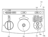
- FIG. 2 is a schematic plan view of an operation panel of the apparatus of FIG. 1.
- the disassembled perspective view which shows the internal structure of the apparatus of FIG.
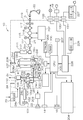
- FIG. 2 is a system diagram of the apparatus of FIG. 1.
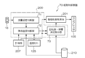
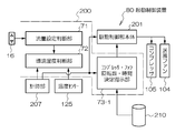
- the block block diagram as the 1st Embodiment of this invention.
- the flowchart which shows an example of the operation control of the 1st Embodiment of this invention.
- the block block diagram as the 2nd Embodiment of this invention.
- the flowchart which shows an example of the operation control of the 2nd Embodiment of this invention.
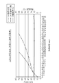
- the graph which shows an example of the relationship between the operation
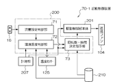
- the block block diagram as the 3rd Embodiment of this invention.
- Explanatory drawing which shows the example of a driving
- the flowchart which shows an example of the operation control of the 3rd Embodiment of this invention.
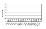
- the graph which shows the pressurization time at the time of starting of an oxygen concentrator.
- FIG. 1 is an external perspective view of an oxygen concentrator according to an embodiment of the present invention
- FIG. 2 is a schematic plan view of an operation panel thereof.
- the oxygen concentrating device 10 includes, for example, a vertically long main body case 11 provided with a handle 12 serving as a handle at the upper end.
- the internal structure excluding the main body case 11 is shown in FIG.
- the operation panel 13 provided with a slight forward tilt is arranged in order from the left, a dial type power switch 14, an oxygen outlet 15, an oxygen flow rate setting switch 16, for example, an LED or a liquid crystal
- An oxygen flow rate display unit 18 for displaying with segment numbers is provided for display and the like.
- a coupler 21 which is engaged with a stepped portion formed in the oxygen outlet 15 in an airtight manner and is detachable.
- the coupler 21 is set so that an opening of a tube 23 such as a nasal cannula 22 is communicated.
- the carrier 25 used during movement such as when going out can be fixed to the bottom lid 26 with two fixing screws.
- holes 10b that can accommodate the rubber feet 27 are formed at corresponding positions, and resin free casters are arranged at four corners as shown in the figure.
- FIG. 2 shows the operation panel 13 described above in an enlarged manner.
- the power switch 14 is operated between the illustrated OFF position and the ON position rotated clockwise by about 90 degrees.
- an operation state lamp having a built-in light emitting LED or the like that lights in green and red. Further, a battery remaining amount monitor is provided above the operation state lamp.
- an alarm display unit in which characters of “check” or a character display corresponding to this is printed horizontally is arranged.
- an oxygen lamp having a built-in light emitting LED that is lit in green, red, and yellow is provided below this alarm display portion.
- the oxygen flow rate setting switch 16 is provided as flat switches 16a and 16b printed with up and down arrows. This oxygen flow rate setting switch 16 changes the oxygen flow rate every time the oxygen concentrated to about 90% or more is pressed in a 0.25L step or a 0.01L step from 0.25L (liter) per minute to a maximum of 5L. It is configured to be configurable. Then, the oxygen generation capacity can be changed by displaying the flow rate setting at that time on the upper oxygen flow rate display unit 18.
- the tuning lamp 19 is provided to notify the patient by lighting or flashing that the concentrated oxygen is being operated in an intermittent supply state by breathing synchronization.
- FIG. 3 is a three-dimensional exploded view seen from the back side in order to show the internal configuration of the oxygen concentrator 10.
- a resin-made bottom lid 26 with rubber feet 27 fixed to the four corners is fixed to the bottom surface of the resin-made base body 40 from below using a plurality of fixing screws.
- the base body 40 is formed in a box shape in which wall surfaces continuously formed from the four surfaces upward are integrally formed. As shown in the drawing, the connectors 131 and 130 are fixed on the back wall surface. ing.
- Exhaust ports 40c, 40c that face each exhaust port of a back cover (not shown) provided in the case main body 11 described in FIG. 1 and communicate with a power supply chamber provided in the case main body 11 are drilled as shown. Has been.
- the upper surface of the base body 40 is formed flat as shown.
- the base body 40 is provided with upright portions 40f provided with holes for fixing with fixing screws from three sides of the left and right surfaces and the rear surface of the two-stage soundproof chamber 34 formed as shown in FIG. It is integrally molded. Further, an exhaust opening 40b communicating with the power supply chamber is further drilled.
- the two-stage soundproof chamber 34 is provided on a lower step member 37 that is fixed to two blower fans 104 on an upper member 36 that can be taken in and out from the side of the front side of the drawing, and that can also be taken in and out from the side.
- the sealed box 35 in which the compressor 105 serving as the compressed air generating unit is disposed in a vibration-proof state is made of the light metal plate as described above.
- a soundproof chamber lid 39 shown on the front side and a soundproof chamber lid 38 shown on the back side are fixed with a plurality of fixing screws as shown in the drawing.
- the two-stage soundproof chamber 34 is integrally provided with a mounting portion that is bent as shown in the figure and in which an insert nut is implanted.
- a soundproof material 51 is laid in the soundproof room.
- the outer peripheral surface is a vibration damping member, and a sheet-like material made of a mixture of synthetic rubber and special resin material is laid, and the two-stage soundproof chamber 34 itself made of a thin aluminum plate is caused by resonance or the like. Vibration is prevented.
- a first opening 35a (shown by a solid line) and a first opening 35a (shown by a broken line) are formed in the left and right side wall surfaces above the upper member 36 of the two-stage soundproof chamber 34, and the outside air is introduced into the inside.
- the upper member 36 is provided with a plurality of fixing holes for fixing the pipe 24 described in FIG. 4 via rubber bushes, and supports the pipe 24 and has a vibration and vibration isolating function with the rubber bush. It is configured to work together.
- Each blower fan 104 may be an inverter-controlled sirocco fan, for example.
- Each blower fan 104 is fixed to the upper member 36 using a bracket so that each blower port faces downward.
- the three-way switching valves 109a, 109b and the like are arranged between the blower fans 104. Further, each fan 104 is provided with a fan rotation detection unit 126.
- the fan rotation detection unit can use, for example, a rotation detector such as an interrupter type photosensor.
- Cylindrical suction cylinders 108 a and 108 b are arranged side by side with the intake buffer tank 101 on the left side wall surface of the two-stage soundproof chamber 34.
- the cylindrical suction cylinders 108a and 108b and the intake buffer tank 101 are fixed by a band 49 to a fixture 49k fixed to the side wall surface. That is, the band 49 is passed through the fixture k, and the band 49 is wound around the cylindrical suction cylinders 108a and 108b and the intake buffer tank 101 and tightened up to be fixed as illustrated.
- the suction cylinder 108 is placed on the upper surface of the base body 40, but the buffer tank having a long overall length is partially inserted and fixed in the opening 40d.
- the product tank 111 is made of polyethylene resin to be vacuum-formed, and is disposed above the two-stage soundproof chamber 24 along the longitudinal direction as shown in the figure.
- the shielding plate 32 is also made of resin for weight reduction.
- the shielding plate 32 is provided with a speaker 23 and an external connector 133 as shown in the figure, and an attachment portion that also serves as a reinforcement fixed to the outer wall surface above the two-stage type soundproof chamber 34 using a fixing screw is integrated. Molding.
- the heat dissipating members 52 and 53 are fixed to the upper wall surface of the two-stage soundproof chamber 34 with fixing screws, and each of the control boards 200 (a board including a CPU 200 described later) and 201 (a board including a motor control unit).
- FIG. 4 is a system diagram (pipe diagram) of the oxygen concentrator 10.
- the double line is a flow path of air, oxygen, and nitrogen gas, and is generally indicated by pipes 24a to 24g.
- a thin solid line indicates power supply or electric signal wiring.
- a compressor 105 compressed air generating unit
- a decompressing unit negative pressure generating unit
- the present invention is not limited to this configuration, and it goes without saying that the compressed air generating unit and the negative pressure generating unit may be configured separately.
- the front cover and the back cover (a part of the case body 11) for introducing outside air into the inside through the intake port and discharging to the outside through the exhaust port are shown as broken containers in the figure as a sealed container.
- the air (outside air) passes through the outside air introduction filter 20 built in the filter replacement lid and the oxygen (outside air) flows in the direction of arrow F inside the oxygen concentrator 100. be introduced.
- This air enters the two-stage soundproof chamber 34 by the air blown by the pair of blower fans 104 and 104.
- the blower fans 104 and 104 are disposed on the upper member, and the compressor 105 is disposed on the lower member in a vibration-proof state. Air enters the two-stage soundproof chamber 34 through an opening formed in the side surface.
- an opening of the pipe 24a is provided in the two-stage soundproof chamber 34, and is provided in the middle of the pipe 24a.
- An intake filter 101 that performs secondary filtration and a large-capacity intake muffler 102 are provided. With this configuration, the intake noise of the raw material air is reduced so that the intake noise of the raw material air remains in the two-stage soundproof chamber 34.
- this two-stage soundproof chamber 34 is made of a reinforced light alloy, aluminum alloy, titanium alloy plate or other suitable material having a thickness of about 0.5 mm to 2.0 mm for weight reduction.
- a compressor 105 which preferably includes a compression means 105a for compressing raw material air to generate compressed air, and a decompression means 105b, is fixed in a vibration-proof state.
- a temperature sensor 125 is disposed at a place where the temperature environment is substantially the same (refer to FIG. 3 together).
- the filtered raw material air is pressurized by the compression means 105a of the compressor 105 to become compressed air.
- the temperature rises and is sent to the pipe 24c, so that the pipe 24c has a light weight excellent in heat dissipation effect. It is good to cool with the ventilation from the ventilation fan 104.
- zeolite which is an adsorbent whose function is reduced at high temperatures, can function sufficiently as an adsorbent for generating oxygen by adsorption of nitrogen, concentrating oxygen to about 90% or more. It will be possible.
- Compressed air is alternately supplied to the first adsorption cylinder body 108a and the second adsorption cylinder body 108b as the adsorption portion via the pipe 24c.
- switching valves three-way switching valves
- 109a and 109b are connected as shown.
- a pipe 24f communicating with the pressure reducing means 105b in order to desorb unnecessary gases from the first adsorption cylinder 108a and the second adsorption cylinder 108b (to perform purging).
- a plurality of (at least two) negative pressure breaking first valves 120 and negative pressure breaking second valves (pressure regulating valves) 121 are arranged in series. As will be described later by opening these, the pressure in the pipe 24f is reduced to near atmospheric pressure during the pressure equalization process, and when the pressure is below a predetermined flow rate, the pressure is appropriately controlled to reduce compressor vibration and reduce the current. ing.
- zeolite As an example of the catalyst adsorbent stored in the first adsorption cylinder 108a and the second adsorption cylinder 108b, for example, zeolite is used.
- a check valve, an equal pressure valve 107 including a throttle valve and an on-off valve is branched and connected to the outlet side above the first adsorption cylinder 108a and the second adsorption cylinder 108b.
- a pipe 24d is formed on the downstream side of the equal pressure valve 107 so as to join the outlets above the first adsorption cylinder 108a and the second adsorption cylinder 108b.
- oxygen having a concentration of about 90% or more generated by separation between the first adsorption cylinder 108a and the second adsorption cylinder 108b is sent.
- the oxygen is piped as shown in a product tank 111 which is a container for storing the oxygen.
- a pressure sensor 208 for detecting the pressure in each adsorption cylinder is piped as shown.
- a pressure regulator 112 that automatically adjusts the oxygen pressure on the outlet side to a constant level is piped downstream of the product tank 111.
- a zirconia-type or ultrasonic-type oxygen (concentration) sensor 114 is connected to the downstream side of the pressure regulator 112 so that the oxygen concentration is detected intermittently (every 10 to 30 minutes) or continuously. I have to.
- a proportional opening valve 115 that opens and closes in conjunction with the oxygen flow rate setting switch 16 is connected to the downstream side, and an oxygen flow rate sensor 116 is connected to the downstream side.
- a demand valve 117 is connected downstream of the sensor 116 via a negative pressure circuit board for respiratory synchronization control, and is connected to the oxygen outlet 15 of the oxygen concentrator 10 via the sterilization filter 119. Yes.
- the power supply system of the oxygen concentrator 10 has the following structure.
- An AC power connector 130 is connected to a switching regulator AC adapter 19 that rectifies AC (commercial AC) power to a predetermined DC voltage.
- the AC power connector 130 is connected to the power control circuit 226.
- the apparatus main body has a built-in battery 228. Moreover, it has the external battery 227 provided so that attachment or detachment is possible via the connector 131 provided in the apparatus, and each battery is connected to the power supply control circuit 226.
- the built-in battery 228 and the external battery 227 are rechargeable secondary batteries, and the built-in battery 228 is charged by receiving power from the power supply control circuit 226.
- At least the built-in battery 228 can be repeatedly charged and discharged at least about 500 times (several hundred times), and has a management function such as the remaining battery level, the number of charge / discharge cycles used, the degree of deterioration, and the output voltage. It is preferable to have a management function capable of confirming the remaining battery capacity, remaining charge capacity, and number of charge / discharge cycles with an external portable terminal.
- the external battery 227 can be charged by receiving power from the power supply control circuit 226 in the connected state via the connector 131, but is normally repeatedly charged using a separately prepared battery charger. Or you may prepare as the external battery 227 which integrated the battery charger designed exclusively.
- the oxygen concentrator has a first power supply state that operates by receiving power supply from the AC adapter 19, and a second power supply state that operates by receiving power supply from the built-in battery 228. It is automatically switched to one of three power supply states, ie, a third power supply state that operates by receiving power supply from an external battery.
- the power supply control circuit 226 is controlled by the central controller 200 so that the priority for this automatic switching is automatically determined in the order of the first power supply state, the third power supply state, and the second power supply state. Further, the power control circuit 226 and the built-in battery 228 are arranged on the bottom surface as described later in order to lower the center of gravity of the oxygen concentrator 100.
- the external battery 227 can be used when going out by being built in the housing portion of the carrier 25 as described above. Since the external battery 227 is provided with the remaining charge display section and the like, the remaining usage time can be known together with the voice guide.
- the AC adapter 19 can generate a predetermined DC voltage without being affected by the difference in frequency and voltage fluctuation, and is preferably a switching regulator type that can be configured to be small and light, but a normal transformer type may also be used.
- the built-in battery 228 and the external battery 227 are preferably lithium ion or lithium hydrogen ion secondary batteries that have little memory effect during charging and can be fully charged even during recharging, but may be conventional nickel-cadmium batteries. Further, in preparation for an emergency, the external battery may be configured as a box of AA dry batteries that can be obtained anywhere.
- the central control unit 200 of the oxygen concentrator 100 has a function of switching to an optimal operation mode according to the amount of oxygen to be generated, and automatically generates a large amount of oxygen for the compressor 105 and the blower fan 104.
- the built-in battery 228 is particularly preserved by performing control to rotate at a high speed and at a low speed when a small amount of oxygen is generated. As a result, even if the external battery 227 is forgotten to be charged, consideration is given so that it is possible to cope with a sudden outing or a power failure.
- central control unit 200 is connected to a motor control unit 201 that performs drive control of a DC motor that is a rotating body of the compressor 105 and a motor of the blower fan 104, and the above-described speaker 23.
- a control unit 203 is connected.
- the central control unit 200 incorporates a ROM that stores a predetermined operation program, and is further connected to a storage device 210, a volatile memory 205, a temporary storage device 206, and a real time clock 207, via an external connector 133. By connecting to a communication line or the like, it is possible to access stored contents.
- the three-way switching valves 109a and 109b, the equal pressure valve 107, the negative pressure generator 105b for desorbing unnecessary gas in the first adsorption cylinder 108a and the second adsorption cylinder 108b, and the pipe 24f A negative pressure breaking first valve 120, a negative pressure breaking second valve 121, an oxygen concentration sensor 114, a proportional opening valve 115, a flow sensor 116, and a valve for controlling the demand valve 117 and a flow control unit for controlling the pressure. 202 is connected to the central control unit 200.
- the compressor 105 having a total weight of about 1 kg is a variable speed controller built in the motor control unit 201, and the driving sound of the motor 105 is controlled by a sine wave driving waveform to lower the operation sound.
- the compressor 105 can be operated at various speeds, can generate the required vacuum (negative pressure) / positive pressure level and flow rate, generates only a little noise and vibration, generates a little heat, It is preferable that it is small and light and can be operated with little power consumption.
- the speed of the compressor 105 can be freely changed based on the activity level and environmental conditions of the patient.
- the demand valve 117 determines that the patient's oxygen demand is relatively low, such as when the patient is sitting or sleeping, by the respiratory synchronization
- the drive rotation speed of the compressor 105 can be automatically reduced. it can. It can also automatically increase speed when it is determined that the patient's oxygen demand is relatively high and the oxygen demand has increased, such as when the patient is standing, active, or at a high altitude with a low oxygen concentration. It is configured to be able to.
- the motor control described above reduces the power consumption of the oxygen concentrator 10 as a whole, extending the life of the rechargeable battery and reducing the weight and size of the rechargeable battery. Reliability can be improved by lowering the degree of wear and extending the service life.
- the compressor 105 has both functions of generating compressed air and generating negative pressure as described above, and the rotation speed is automatically controlled according to the oxygen flow rate taken out. Specifically, the rotation speed is controlled between 500 rpm and 3000 rpm, and the operation life when rotating at a normal speed of about 1700 rpm can be extended to 15000 hours.
- the compressor 105 has a performance of compressing air to 100 kPa, preferably about 75 kPa. In addition, it has a function of notifying by voice guidance when the above operation life has passed.
- a DC brushless fan is used as a fan motor that drives the blower fan 104, which is a cooling fan, and the rotation speed control can be easily performed by PWM control or voltage control.
- FIG. 5 is a diagram illustrating a configuration of the activation control device 70 of the oxygen concentrator 10 as the first embodiment.
- a range indicated by a chain line that is, a range indicated by reference numeral 200 can be realized by utilizing a part of the configuration of the central control unit 200 of FIG. That is, the central control unit 200 is a control circuit (IC) including a control unit composed of a CPU (Central Processing Unit) for controlling the whole, and the central control unit 200 includes a real-time clock as a time measuring unit 207, A temperature sensor 125 and a storage device 210 are connected.
- IC control circuit
- CPU Central Processing Unit
- a part of the storage device 210 can also be arranged inside the central control unit 200, and usually includes a RAM (Random Access Memory), a ROM (Read Only Memory), a flash memory, and the like. Connected with the device via the bus.
- the CPU described above performs processing of a predetermined program and controls a ROM and the like connected to the bus.
- the ROM stores various programs and various information.
- the RAM has a function as an area for comparing the contents of the memory during the program processing by the CPU and for developing and executing the program.
- a compressor 105 is connected to the central control unit 200 via a drive control unit main body 201.
- the central control unit 200 includes an environmental temperature determination unit 72 that determines an environmental temperature as an operating environment of the compressor.
- the environmental temperature determination unit 72 and the storage device 210 are connected to a rotation speed / time determination instruction unit 73 included in the central control unit 200.
- the storage device 210 stores the relationship between the environmental temperature of the compressor 105 and the rotational speed of the motor that is the driving means of the compressor 105 in the form of predetermined table data or the like.
- the rotation speed / time determination instruction unit is connected to, for example, a motor drive circuit (motor control unit 201) as the drive control unit main body 201, and the motor drive circuit is connected to the compressor 105.
- the environmental temperature determination unit 72 obtains the set flow rate information from the flow rate setting determination unit 71, and when the set flow rate is a low flow rate, the relationship between the flow rate and the environmental temperature is referred to by referring to the data in the storage device 210. I see. In the data of the storage device 210, at the low flow rate, the temperature rise at which the compressor 105 is heated is slow, and a leak occurs in the compressor 105 in relation to the environmental temperature (provided at the piston tip of the compressor 105, For example, the outer diameter of the piston cup, which is a shallow cup-shaped member as shown in Fig. 15 or the like, is reduced due to the relationship between the environmental temperature and the temperature expansion coefficient. If there is a gap between them, air leakage will occur), and if it is recorded in advance, a command based on the data is issued.
- the environmental temperature determination unit 72 instructs the rotation number / time determination instruction unit 73 to increase the motor rotation number of the compressor 105 and increase the air pressure to increase the temperature and reduce the diameter of the piston cup.
- the number of revolutions at which the outer diameter can be made the original size and the operation time at the number of revolutions are transmitted.
- the rotation number / time determination instruction unit 73 is configured to transmit the rotation number and the operation time to the drive control unit main body (motor control unit) 201.
- the drive control unit main body 201 is configured to control the compressor 105, increase the rotation speed of the motor, and issue an instruction to operate at a high rotation speed for a predetermined time.
- FIG. 6 is a flowchart showing an example of operation control of the oxygen concentrator 10 of the present embodiment, and particularly showing control at the time of activation.
- the operation is started when the user turns on the power switch 14 of the operation panel 13 of the oxygen concentrator 10 described in FIGS. 1 and 2 to turn on the power and operates the oxygen flow rate setting switch 16 to set the flow rate. (ST10).
- the flow rate setting determination unit 71 described with reference to FIG. 5 determines whether or not the operation of the generated oxygen flow rate is a low flow rate (ST11). If the flow rate setting determination unit 71 determines that the flow rate is set to a predetermined flow rate that is equal to or higher than a predetermined flow rate, the process proceeds to step 12 to continue operation at a high flow rate as set (ST12).
- step 13 it is determined whether or not the environmental temperature where the oxygen concentrator 10 is placed is low. For example, when the temperature is 10 degrees or less and defined as “low temperature” and stored in the storage device 210, the environmental temperature determination unit 72 in FIG.
- step 14 the process proceeds to step 14 and the operation at the low speed is continued. That is, even if the motor of the compressor 105 is at a low speed, if the ambient environment is not low, it can be determined that the outer diameter of the piston cup has not been reduced so much that there is little leakage.
- the environmental temperature determination unit 72 instructs the rotation speed / time determination instruction unit, and from the data in the storage device 210, From the table data and the like corresponding to the rotation speed and the specific temperature, the rotation speed required for the operation performed here and data of the duration are acquired. Then, the rotation speed / time determination instruction unit 73 causes the motor control unit which is the drive control unit main body 201 to continuously operate at a rotation speed higher than the motor rotation speed of 1000 rpm, for example, 1300 rpm. (ST15).
- the drive control unit main body 201 starts time measurement at the time measuring unit 207 from the start of operation at a high rotational speed, and the determined time, that is, the outer diameter of the piston cup is heated by the increase in pressure to a normal size.
- the operation at a higher rotation speed is continued for the time considered to have returned (ST16), and then the operation is continued at a rotation speed corresponding to the set flow rate that is the normal rotation speed (ST17).
- FIG. 7 is a diagram illustrating a configuration of the activation control device 70 of the oxygen concentrating device 10 as the second embodiment.
- a range indicated by a chain line that is, a range indicated by reference numeral 200 can be realized by utilizing a part of the configuration of the central control unit 200 of FIG. That is, the central control unit 200 is a control circuit (IC) including a control unit composed of a CPU (Central Processing Unit) for controlling the whole, and the central control unit 200 includes a real-time clock as a time measuring unit 207, A temperature sensor 125 and a storage device 210 are connected.
- IC control circuit
- CPU Central Processing Unit
- a part of the storage device 210 can also be arranged inside the central control unit 200, and usually includes a RAM (Random Access Memory), a ROM (Read Only Memory), a flash memory, and the like. Connected with the device via the bus.
- the CPU described above performs processing of a predetermined program and controls a ROM and the like connected to the bus.
- the ROM stores various programs and various information.
- the RAM has a function as an area for comparing the contents of the memory during the program processing and for executing the program.
- a compressor 105 is connected to the central control unit 200 via a drive control unit main body 201.
- the central control unit 200 is connected to the oxygen flow rate setting button 16 to receive a flow rate setting determination unit 71 for grasping the set flow rate set by the user and a measurement signal from the temperature sensor 125.
- the central control unit 200 has an environmental temperature determination unit 72 for determining the environmental temperature as the operating environment of the compressor by grasping the temperature at a location very close to the compressor 105.
- the environmental temperature determination unit 72 and the storage device 210 are connected to a rotation speed / time determination instruction unit 73 included in the central control unit 200.
- the storage device 210 stores the relationship between the environmental temperature of the compressor 105 and the rotational speed of the fan motor of the blower fan 104, which is a cooling fan for cooling the compressor 105, in the form of predetermined table data or the like.
- the rotation speed / time determination instruction unit is connected to, for example, a motor drive circuit (motor control unit 201) as the drive control unit main body 201, and the motor drive circuit is connected to the compressor 105 and the blower fan 104.
- the environmental temperature determination unit 72 obtains the set flow rate information from the flow rate setting determination unit 71, and when the set flow rate is a low flow rate, the relationship between the flow rate and the environmental temperature is referred to by referring to the data in the storage device 210. I see. In the data of the storage device 210, at the low flow rate, the temperature rise at which the compressor 105 is heated is slow, and a leak occurs in the compressor 105 in relation to the environmental temperature (the outer diameter of the piston cup of the compressor 105 is the environment). Based on the data, if recorded in advance, the diameter is reduced due to the relationship between temperature and temperature expansion coefficient, and a gap is generated between the cylinder and air leaks. Issue a command.
- the environmental temperature determination unit 72 instructs the rotation speed / time determination instruction unit 73 to stop the rotation of the fan motor (not shown) of the blower fan 104 or reduce the rotation speed.
- the compressor 105 is not cooled or not cooled excessively, and the fan rotation is performed so that the outer diameter of the reduced diameter piston cup can be restored to the original size, and the state is continued. It tells the driving time.
- the rotation number / time determination instruction unit 73 is configured to transmit the rotation number and the operation time to the drive control unit main body (motor control unit) 201.
- the drive control unit main body 201 is configured to control the blower fan 104, increase the rotation speed of the motor, and issue an instruction to operate at a high rotation speed for a predetermined time.
- FIG. 8 is a flowchart showing an example of operation control of the oxygen concentrator 10 of the present embodiment, and particularly showing control at the time of activation.
- the operation is started when the user turns on the power switch 14 of the operation panel 13 of the oxygen concentrator 10 described in FIGS. 1 and 2 to turn on the power and operates the oxygen flow rate setting switch 16 to set the flow rate. (ST20).
- the flow rate setting determination unit 71 described with reference to FIG. 5 determines whether or not the operation of the generated oxygen flow rate is a low flow rate (ST21). If the flow rate setting determination unit 71 determines that the flow rate is set to a predetermined flow rate that is equal to or higher than a predetermined flow rate, the process proceeds to step 12, and the operation at a high flow rate as set is continued (ST22).
- step 13 it is determined whether or not the environmental temperature where the oxygen concentrator 10 is placed is low. For example, when the temperature is 10 degrees or less and defined as “low temperature” and stored in the storage device 210, the environmental temperature determination unit 72 in FIG.
- step 14 the process proceeds to step 14 and the operation at the low speed is continued. That is, even if the motor of the compressor 105 is at a low speed, if the ambient environment is not low, it can be determined that the outer diameter of the piston cup has not been reduced so much that there is little leakage.
- the environmental temperature determination unit 72 instructs the rotation speed / time determination instruction unit, and from the data in the storage device 210, Data relating to the operation of the blower fan required in the operation performed here is acquired from the corresponding table data or the like depending on the rotation speed and the specific temperature.
- the rotation speed / time determination instruction unit 73 stops the blower fan 104 based on the data (ST25), or the fan rotation speed corresponding to the set flow rate determined by default is set.
- a low fan rotation number is obtained, and an instruction is given to the motor control unit, which is the drive control unit main body 201, for how many rotations and how long it continues (ST24).
- the drive control unit main body 201 starts time measurement by the time measuring unit 207 from the stop of the blower fan 104 or the start of the operation at the low rotation drive, and the determined time, that is, the outer diameter of the piston cup is heated by increasing the pressure.
- the blower fan 104 is stopped or stopped at a low speed for a time period that is considered to have returned to the normal size (ST26), and then coincides with the default fan speed determined in accordance with the speed of the compressor 105.
- the rotational speed of the blower fan 104 is determined and the operation is continued (ST27). Referring to FIG.
- FIG. 10 is a diagram illustrating a configuration of the activation control device 80 of the oxygen concentrating device 10 as the third embodiment.
- the range indicated by the chain line of the activation control device 80 that is, the range indicated by reference numeral 200 can be realized by using a part of the configuration of the central control unit 200 of FIG. 4.
- the portions denoted by the same reference numerals as those in FIG. 5 have the same configuration, and therefore, a common description is omitted, and hereinafter, differences will be mainly described.
- the activation control device 80 in FIG. 10 differs from that in FIG. 5 in that the blower fan 104 also performs special control at the time of activation.
- the compressor 105 and the blower fan 104 are both controlled to rotate, and the storage device 210 stores data for that purpose. After determining the environmental temperature, the compressor 105 and the blower fan 104 are driven by the compressor / fan rotation speed / time determination instruction unit 73-1.
- the blower fan 104 in the oxygen concentrator 10 is a cooling fan for cooling the pressure that is increased due to the driving of the compressor 105 and the temperature becomes high. Therefore, conventionally, when the rotation speed of the compressor is 1000 rotations per minute, that is, when the rotation speed of the motor built in the compressor is as low as 1000 rpm, cooling is performed by driving the blower fan. This means that there is cooling “Yes”. In this case, the compressed air integrated flow rate 15L after 3 minutes passed, and the integrated flow rate 26L after 5 minutes were obtained. However, even if the compressor rotational speed is set to 1000 at the time of startup in FIG.
- the compressed air integrated flow rate 14L after 3 minutes has elapsed, and the integrated flow rate 28L after 5 minutes has elapsed.
- the integrated flow rate can be significantly improved, such as the compressed air integrated flow rate 25L after 3 minutes and the integrated flow rate 39L after 5 minutes.
- FIG. 12 is a flowchart showing an example of operation control of the oxygen concentrator 10 of the present embodiment, and particularly showing control at the time of startup.
- the operation is started when the user turns on the power switch 14 of the operation panel 13 of the oxygen concentrator 10 described in FIGS. 1 and 2 to turn on the power and operates the oxygen flow rate setting switch 16 to set the flow rate. (ST30).
- the flow rate setting determination unit 71 described with reference to FIG. 10 determines whether or not the operation of the generated oxygen flow rate is a low flow rate (ST31).
- the process proceeds to step 32 to continue operation at a high flow rate as set (ST32).
- a high flow rate for example, in the operation mode in which the oxygen flow rate is 2 L, for example, the compressor rotation speed is set to 1700 rpm and the blower fan rotation speed is set to 2500 rpm.
- the compressor rotation speed is 2700 rpm and the blower fan rotation speed is 3700 rpm.
- the oxygen flow rate set via the oxygen flow rate setting switch 16 exceeds, for example, 1 L (oxygen flow rate of 1 liter per minute)
- the increase in the pressure of compressed air by the compressor 105 is compared. Since the piston cup outer diameter becomes a normal size relatively quickly, the operation is continued without taking measures against piston leakage.
- step 33 it is determined whether or not the environmental temperature where the oxygen concentrator 10 is placed is low (ST33). For example, when the temperature is 10 degrees or less and defined as “low temperature” and stored in the storage device 210, the environmental temperature determination unit 72 in FIG. 10 determines that the operating environment is not “low temperature”. In this case, the process proceeds to step 34, where the operation at the default value, that is, the operation at the low rotation speed is continued, and the blower fan 104 is also driven to perform cooling. This is to prevent the compressor 105 from being heated (ST34).
- the compressor rotational speed is set to 1000 rpm, and the rotational speed of the blower fan is set to 1600 rpm. That is, even if the motor of the compressor 105 is at a low speed, if the ambient environment is not low, it can be determined that the outer diameter of the piston cup has not been reduced so much that there is little leakage.
- the environmental temperature determination unit 72 instructs the compressor / fan rotation speed / time determination instruction unit 73-1 to store it. From the data of the apparatus 210, from the table data etc. in which the rotational speeds of the compressor and the fan correspond to the ambient temperature, the rotational speed of the motor and the rotational speed of the blower fan 104 required in the operation performed here, and the operation Get data about duration.
- the threshold for determining whether or not the ambient temperature is low is determined by measuring in advance the ambient temperature at which the outer diameter of the piston cup in the compressor 105 of the oxygen concentrator 105 is reduced, and the storage device 210. Can be stored.
- the threshold is, for example, 10 degrees.
- the compressor / fan rotation speed / time determination instructing unit 73-1 gives the motor control unit, which is the drive control unit main body 201, a rotation speed higher than the motor rotation speed of 1000 rpm continuously for how many rotations and how long, For example, the operation at 1300 rpm is instructed and the blower fan 104 is not rotated.
- the drive control unit main body 201 starts time measurement at the time measuring unit 207 from the start of operation at a high rotational speed, and the determined time, that is, the outer diameter of the piston cup is heated by the increase in pressure to a normal size.
- the operation at a high rotation speed (for example, 1300 rpm) is continued for the time considered to have returned, for example, for 3 minutes, and during that time, the blower fan 104 is stopped (ST35).
- a predetermined time for example, 3 minutes, is passed, and the warming time of the compressor 105 due to the pressure rise is taken (ST36).
- the compressor rotational speed is lowered while the blower fan 104 is stopped.
- the compressor 105 is set to 1000 rpm and continuously operated for a predetermined time, for example, 7 minutes (ST37, ST38).
- the reason why the blower fan is stopped and the compressor rotational speed is lowered is to prevent the compressor temperature from being unnecessarily lowered while realizing the set flow rate.
- the blower fan 104 is driven, and the operation is continued with a default value of a low flow rate, for example, the compressor rotational speed is 1000 rpm and the rotational speed of the blower fan is 1600 rpm (ST39).
- an oxygen concentrator that can supply stable raw material air to the adsorbing portion immediately after startup even when it is started in a low rotation region.
- the present invention is not limited to the embodiments described above.
- the rotation speed of the compressor and the rotation speed of the blower fan can be appropriately determined depending on the size and capacity of the oxygen concentrator.
- a part of the matters described in the above embodiments may be omitted, and the scope of the present invention is not deviated by combining with other configurations not described above.
Landscapes
- Health & Medical Sciences (AREA)
- Emergency Medicine (AREA)
- Chemical & Material Sciences (AREA)
- Pulmonology (AREA)
- Engineering & Computer Science (AREA)
- Animal Behavior & Ethology (AREA)
- Biomedical Technology (AREA)
- Heart & Thoracic Surgery (AREA)
- Hematology (AREA)
- Life Sciences & Earth Sciences (AREA)
- Anesthesiology (AREA)
- General Health & Medical Sciences (AREA)
- Public Health (AREA)
- Veterinary Medicine (AREA)
- Otolaryngology (AREA)
- Analytical Chemistry (AREA)
- Organic Chemistry (AREA)
- Inorganic Chemistry (AREA)
- General Chemical & Material Sciences (AREA)
- Oil, Petroleum & Natural Gas (AREA)
- Chemical Kinetics & Catalysis (AREA)
- Oxygen, Ozone, And Oxides In General (AREA)
- Separation Of Gases By Adsorption (AREA)
Abstract
【課題】低回転領域で起動した場合にも起動直後から安定した原料空気を吸着部に供給することができる酸素濃縮装置を提供すること。 【解決手段】回転体を内蔵して圧縮空気を発生する圧縮空気発生部と、前記圧縮空気を内部に導入して該内部に充填された吸着剤により窒素を吸着して酸素を分離生成する吸着部とを備える酸素濃縮装置において、前記圧縮空気発生部は、生成する前記酸素流量に応じて前記回転体の回転数が適切な回転数となるように制御する制御部200を有しており、該制御部は、装置起動時に前記回転体の回転数を前記決められた回転数よりも高い回転数で駆動する構成とした。
Description
本発明は、空気中から酸素を分離生成する酸素濃縮装置の改良に関する。
肺に疾病を抱える患者が高濃度の酸素を吸引するために使用する酸素濃縮器は種々提案されており、大気の一部を用いてコンプレッサにより圧縮空気を作り、該圧縮された空気を吸着用の筒体内部に送り込み、該吸着筒体内の吸着剤に窒素を吸着させることにより生成した酸素を、鼻カニューラを用いて、患者に摂取させる比較的コンパクトな酸素濃縮装置としては特許文献1のものが知られている。
従来から、上述のような酸素濃縮装置では、圧縮と減圧の両機能を持つコンプレッサを用いることにより、小型で効率良い装置を実現しているが、他方、比較的振動の発生が大きいという欠点がある。
特許文献1は、本出願による提案によるものであるが、この装置は、このような低酸素流量時の振動を効率良く抑制することを実現したものである。
特許文献1は、本出願による提案によるものであるが、この装置は、このような低酸素流量時の振動を効率良く抑制することを実現したものである。
しかしながら、酸素濃縮装置を起動する際には、別の問題として、以下のような問題がある。
すなわち、図13、図14において、これらグラフの横軸に並ぶ各数字は、それぞれ酸素濃縮装置の各製品16台に対応しており、縦軸は、これらの各装置を起動して、酸素を生成し、バッファタンクに貯留されて90kPaに達するのに要するコンプレッサの加圧時間を示している。
すなわち、図13、図14において、これらグラフの横軸に並ぶ各数字は、それぞれ酸素濃縮装置の各製品16台に対応しており、縦軸は、これらの各装置を起動して、酸素を生成し、バッファタンクに貯留されて90kPaに達するのに要するコンプレッサの加圧時間を示している。
図13では、通常の室温環境を想定した、例えば、摂氏23度(以下、温度表示は全て「摂氏」)に非動作状態で24時間保管した後、比較的低い設定流量(酸素流量)として、1L(リットル)に設定した場合を示している。
低い設定流量とした場合は、吸着筒に送られる圧縮空気量も少ないので、この場合のコンプレッサ回転数は例えば1000rpmである。
図示されているように、16台全ての装置が約12秒程度で90kPaに達している。
低い設定流量とした場合は、吸着筒に送られる圧縮空気量も少ないので、この場合のコンプレッサ回転数は例えば1000rpmである。
図示されているように、16台全ての装置が約12秒程度で90kPaに達している。
図14は、冬場等の比較的低い室温環境を想定した実験の結果を示している。
具体的には、0度で24時間保管して、図13と同様に比較的低い設定流量(酸素流量)として、1L(リットル)に設定して運転したところ、16台全てについて、90kPa程度に達するのに長時間を要し、ひどい場合には60秒近くかかり、所要時間がほぼ5倍に伸びている。
具体的には、0度で24時間保管して、図13と同様に比較的低い設定流量(酸素流量)として、1L(リットル)に設定して運転したところ、16台全てについて、90kPa程度に達するのに長時間を要し、ひどい場合には60秒近くかかり、所要時間がほぼ5倍に伸びている。
このような時間を要した原因を図15、図16を参照して説明する。
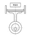
図15は、コンプレッサ内のシリンダ内で動く浅いカップ状の形態をしたピストンカップを示しており、常温時には、シリンダとピストンとの間をほぼ隙間なく接触していてシール性は良好となるようにされている。
しかしながら、図16に示すように、環境温度が低温になると、ピストンカップの外径が収縮して隙間を生じ、隙間からのリークによって圧縮空気を生成する効率が落ちてしまう。
本発明者等の試みによると、コンプレッサ回転数が1300rpm未満で、環境温度が10度以下の場合にこのような傾向があらわれることが確認されている。
図15は、コンプレッサ内のシリンダ内で動く浅いカップ状の形態をしたピストンカップを示しており、常温時には、シリンダとピストンとの間をほぼ隙間なく接触していてシール性は良好となるようにされている。
しかしながら、図16に示すように、環境温度が低温になると、ピストンカップの外径が収縮して隙間を生じ、隙間からのリークによって圧縮空気を生成する効率が落ちてしまう。
本発明者等の試みによると、コンプレッサ回転数が1300rpm未満で、環境温度が10度以下の場合にこのような傾向があらわれることが確認されている。
本発明は上記課題を解決するためになされたものであり、低回転領域で起動した場合にも起動直後から安定した原料空気を吸着部に供給することができる酸素濃縮装置とその起動制御方法を提供することを目的とする。
上記課題は、本発明にあっては、ピストンを駆動する回転体を内蔵して圧縮空気を発生する圧縮空気発生部と、前記圧縮空気を内部に導入して該内部に充填された吸着剤により窒素を吸着して酸素を分離生成する吸着部とを備える酸素濃縮装置において、前記圧縮空気発生部は、生成する前記酸素流量に応じて前記回転体の回転数が適切な回転数となるように制御する制御部を有しており、該制御部は、装置起動時に前記回転体の回転数を前記決められた回転数よりも高い回転数で駆動する構成とした酸素濃縮装置により、達成される。
上記構成によれば、起動時に、圧縮空気発生部に内蔵されるピストンのピストンカップとシリンダとの間の隙間からリークが生じていたとしても、圧縮空気発生部の回転体の回転数を通常よりも高くすることにより、その分必要圧力を得るための加圧時間が短くなり温度の上昇と共に、ピストンカップが膨張し、リークを減少もしくは止めることができるから、沢山の原料空気を送ることができ、必要な量の酸素を確実に得ることができる。
上記構成によれば、起動時に、圧縮空気発生部に内蔵されるピストンのピストンカップとシリンダとの間の隙間からリークが生じていたとしても、圧縮空気発生部の回転体の回転数を通常よりも高くすることにより、その分必要圧力を得るための加圧時間が短くなり温度の上昇と共に、ピストンカップが膨張し、リークを減少もしくは止めることができるから、沢山の原料空気を送ることができ、必要な量の酸素を確実に得ることができる。
酸素濃縮装置が前記生成する酸素流量を切り替える手段を備えており、少ない酸素流量に設定されて運転される際に、該設定された酸素流量に対応して前記回転体について予め決められた回転数よりも高い回転数で駆動する構成とすることができる。
上記構成によれば、装置の運転モードとして、少ない酸素流量に設定されている場合には、圧縮空気発生部の回転体の回転数がもともと少なく、加圧時間がかかるので、ピストンカップとシリンダ間のリーク防止のためにはより有効である。
上記構成によれば、装置の運転モードとして、少ない酸素流量に設定されている場合には、圧縮空気発生部の回転体の回転数がもともと少なく、加圧時間がかかるので、ピストンカップとシリンダ間のリーク防止のためにはより有効である。
装置が置かれる環境温度を検出する手段を備えており、該温度検出手段により所定以下の温度が検出されると、設定された酸素流量に対応して前記回転体について予め決められた回転数よりも高い回転数で駆動する構成とすることができる。
上記構成によれば、装置が置かれる環境温度が低い場合には、圧縮空気発生部に内蔵されているピストンカップとシリンダ間にリークが発生し易いので、圧縮空気発生部の回転体の回転数を通常よりも高くして、加圧時間を短縮し、温度上昇によりピストンカップが膨張するのを抑制して、リークを減少もしくは止めることができる。
また、前記圧縮空気発生部の回転数が高まることによる温度上昇を抑制するための冷却ファンを有し、生成する前記酸素流量に応じて適切なファン回転数となるように制御する制御部を有しており、該制御部は、装置起動時には、当該冷却ファンを停止するか、当該決められたファン回転数よりも低い回転数で駆動する構成とすることができる。
上記構成によれば、冷却ファンを停止するか、あるいは前記酸素流量に対応して決められたファン回転数よりも低い回転数で駆動することによって、圧力の上昇に対応した温度上昇を抑制するための冷却機能を停止させるか低減させることになる。これにより、その分高温となって、ピストンカップが膨張し、リークを減少もしくは止めることができるから、沢山の原料空気を送ることができ、必要な量の酸素を短時間で得ることができる。
上記構成によれば、装置が置かれる環境温度が低い場合には、圧縮空気発生部に内蔵されているピストンカップとシリンダ間にリークが発生し易いので、圧縮空気発生部の回転体の回転数を通常よりも高くして、加圧時間を短縮し、温度上昇によりピストンカップが膨張するのを抑制して、リークを減少もしくは止めることができる。
また、前記圧縮空気発生部の回転数が高まることによる温度上昇を抑制するための冷却ファンを有し、生成する前記酸素流量に応じて適切なファン回転数となるように制御する制御部を有しており、該制御部は、装置起動時には、当該冷却ファンを停止するか、当該決められたファン回転数よりも低い回転数で駆動する構成とすることができる。
上記構成によれば、冷却ファンを停止するか、あるいは前記酸素流量に対応して決められたファン回転数よりも低い回転数で駆動することによって、圧力の上昇に対応した温度上昇を抑制するための冷却機能を停止させるか低減させることになる。これにより、その分高温となって、ピストンカップが膨張し、リークを減少もしくは止めることができるから、沢山の原料空気を送ることができ、必要な量の酸素を短時間で得ることができる。
本発明は、ピストンを駆動する回転体を内蔵して圧縮空気を発生する圧縮空気発生部と、前記圧縮空気を内部に導入して該内部に充填された吸着剤により窒素を吸着して酸素を分離生成する吸着部とを備える酸素濃縮装置の起動制御方法であって、起動時には、起動に際して設定される酸素流量に応じてあらかじめ決められている前記回転体の回転数よりも高い回転数で起動時の運転を行うことを特徴とする酸素濃縮装置の起動制御方法である。
前記起動時に選定された酸素設定流量を判断し、少ない酸素流量に設定されて運転される際に、該設定された酸素流量に対応して前記回転体について予め決められた回転数よりも高い回転数で起動時の運転を行うこととしてもよい。
前記起動時に環境温度を検出して、所定以下の温度が検出されると、設定された酸素流量に対応して前記回転体について予め決められた回転数よりも高い回転数で起動時の運転を行うこととしてもよい。
また、上記課題は、本発明にあっては、ピストンを駆動する回転体を内蔵して圧縮空気を発生する圧縮空気発生部と、前記圧縮空気を内部に導入して該内部に充填された吸着剤により窒素を吸着して酸素を分離生成する吸着部とを備える酸素濃縮装置において、前記圧縮空気発生部により回転数が高まることによる温度上昇を抑制するための冷却ファンを有するとともに、生成する前記酸素流量に応じて適切なファン回転数となるように制御する制御部を有しており、該制御部は、装置起動時には、当該冷却ファンを停止するか、あるいは前記酸素流量に対応して決められたファン回転数よりも低い回転数で駆動する構成とした酸素濃縮装置により、達成される。
上記構成によれば、起動時に、圧縮空気発生部に内蔵されるピストンのピストンカップとシリンダとの間の隙間からリークが生じていたとしても、冷却ファンを停止するか、あるいは前記酸素流量に対応して決められたファン回転数よりも低い回転数で駆動することによって、温度上昇を抑制するための冷却機能を停止させるか低減させることになる。これにより、その分高温となって、ピストンカップが膨張し、リークを減少もしくは止めることができるから、沢山の原料空気を送ることができ、必要な量の酸素を短時間で得ることができる。
上記構成によれば、起動時に、圧縮空気発生部に内蔵されるピストンのピストンカップとシリンダとの間の隙間からリークが生じていたとしても、冷却ファンを停止するか、あるいは前記酸素流量に対応して決められたファン回転数よりも低い回転数で駆動することによって、温度上昇を抑制するための冷却機能を停止させるか低減させることになる。これにより、その分高温となって、ピストンカップが膨張し、リークを減少もしくは止めることができるから、沢山の原料空気を送ることができ、必要な量の酸素を短時間で得ることができる。
前記生成する酸素流量を切り替える手段を備えており、少ない酸素流量に設定されて運転される際に、該設定された酸素流量に対応して前記冷却ファンについて予め決められたファン回転数よりも低い回転数で駆動する構成することができる。
上記構成によれば、装置の運転モードとして、少ない酸素流量に設定されている場合には、圧縮空気発生部の回転体の回転数がもともと少なく、加圧時間がかかるので、その分温度上昇が緩やかであるから、冷却ファンの回転数も低くすることにより、ピストンカップとシリンダ間のリーク防止をより確実にすることができる。
上記構成によれば、装置の運転モードとして、少ない酸素流量に設定されている場合には、圧縮空気発生部の回転体の回転数がもともと少なく、加圧時間がかかるので、その分温度上昇が緩やかであるから、冷却ファンの回転数も低くすることにより、ピストンカップとシリンダ間のリーク防止をより確実にすることができる。
装置が置かれる環境温度を検出する手段を備えており、該温度検出手段により所定以下の温度が検出されると、設定された酸素流量に対応して冷却ファンを停止するか、あるいは前記酸素流量に対応して決められたファン回転数よりも低い回転数で駆動する構成とすることができる。
上記構成によれば、装置が置かれる環境温度が低い場合には、圧縮空気発生部に内蔵されているピストンカップとシリンダ間にリークが発生し易いので、設定された酸素流量に対応して冷却ファンを停止するか、あるいは前記酸素流量に対応して決められたファン回転数よりも低い回転数で駆動すると、その分温度上昇し易いので、ピストンカップが膨張を抑制して、リークを減少もしくは止めることができる。
前記圧縮空気発生部は、生成する前記酸素流量に応じて前記回転体の回転数が適切な回転数となるように制御する制御部を有しており、該制御部は、装置起動時に前記回転体の回転数を前記決められた回転数よりも高い回転数で駆動する構成とすることができる。
上記構成によれば、起動時に圧縮空気の圧力上昇を抑制することができ、その分、ピストンカップが膨張を抑制して、リークを減少もしくは止めることができるから、沢山の原料空気を送ることができ、必要な量の酸素を短時間で得ることができる。
上記構成によれば、装置が置かれる環境温度が低い場合には、圧縮空気発生部に内蔵されているピストンカップとシリンダ間にリークが発生し易いので、設定された酸素流量に対応して冷却ファンを停止するか、あるいは前記酸素流量に対応して決められたファン回転数よりも低い回転数で駆動すると、その分温度上昇し易いので、ピストンカップが膨張を抑制して、リークを減少もしくは止めることができる。
前記圧縮空気発生部は、生成する前記酸素流量に応じて前記回転体の回転数が適切な回転数となるように制御する制御部を有しており、該制御部は、装置起動時に前記回転体の回転数を前記決められた回転数よりも高い回転数で駆動する構成とすることができる。
上記構成によれば、起動時に圧縮空気の圧力上昇を抑制することができ、その分、ピストンカップが膨張を抑制して、リークを減少もしくは止めることができるから、沢山の原料空気を送ることができ、必要な量の酸素を短時間で得ることができる。
本発明は、ピストンを駆動する回転体を内蔵して圧縮空気を発生する圧縮空気発生部と、前記圧縮空気を内部に導入して該内部に充填された吸着剤により窒素を吸着して酸素を分離生成する吸着部と、前記圧縮空気発生部の圧力及び回転数が高まることによる温度上昇を抑制するための冷却ファンとを備える酸素濃縮装置の起動制御方法であって、起動時には、当該冷却ファンを停止するか、あるいは前記酸素流量に対応して決められたファン回転数よりも低い回転数で駆動することを特徴とする。
前記起動時に選定された酸素設定流量を判断し、少ない酸素流量に設定されて運転される際に、該設定された酸素流量に対応して前記冷却ファンについて予め決められたファン回転数よりも低い回転数で起動時の運転を行うことができる。
前記起動時に環境温度を検出して、所定以下の温度が検出されると、設定された酸素流量に対応して冷却ファンを停止するか、あるいは前記酸素流量に対応して決められたファン回転数よりも低い回転数で起動時の運転を行うことができる。
以上説明したように、本発明によれば、低回転領域で起動した場合にも起動直後から安定した原料空気を吸着部に供給することができる酸素濃縮装置とその駆動制御方法を提供することができる。
以下、この発明の好適な実施の形態を添付図面等を参照しながら、詳細に説明する。
尚、以下に述べる実施の形態は、本発明の好適な具体例であるから、技術的に好ましい種々の限定が付されているが、本発明の範囲は、以下の説明において特に本発明を限定する旨の記載がない限り、これらの態様に限られるものではない。
尚、以下に述べる実施の形態は、本発明の好適な具体例であるから、技術的に好ましい種々の限定が付されているが、本発明の範囲は、以下の説明において特に本発明を限定する旨の記載がない限り、これらの態様に限られるものではない。
図1は、本発明の実施の形態にかかる酸素濃縮装置の外観斜視図、図2はその操作パネルの概略平面図である。
これらの図において、酸素濃縮装置10は、たとえば、上端に取っ手となるハンドル12を設けた縦長の本体ケース11を備えている。
本体ケース11を除く内部構造は、後述する図3に示されている。
本体ケース11の上端付近において、やや前傾して設けた操作パネル13には、左から順に、ダイヤル式の電源スイッチ14と、酸素出口15と、酸素流量設定スイッチ16と、例えば、LEDまたは液晶表示等にて、セグメント数字で表示を行う酸素流量表示部18が配置されている。また酸素出口15の上方には、該酸素出口15に形成された段差部に対して気密状態に係合されるとともに、着脱自在に設けられるカプラ21が示されている。このカプラ21には鼻カニューラ22等のチューブ23の開口部が連通するようにセットされている。
これらの図において、酸素濃縮装置10は、たとえば、上端に取っ手となるハンドル12を設けた縦長の本体ケース11を備えている。
本体ケース11を除く内部構造は、後述する図3に示されている。
本体ケース11の上端付近において、やや前傾して設けた操作パネル13には、左から順に、ダイヤル式の電源スイッチ14と、酸素出口15と、酸素流量設定スイッチ16と、例えば、LEDまたは液晶表示等にて、セグメント数字で表示を行う酸素流量表示部18が配置されている。また酸素出口15の上方には、該酸素出口15に形成された段差部に対して気密状態に係合されるとともに、着脱自在に設けられるカプラ21が示されている。このカプラ21には鼻カニューラ22等のチューブ23の開口部が連通するようにセットされている。
本体ケース11の底蓋26には、4つのゴム足27が四隅に固定されており、床面上に設置して使用するときに横滑りを防止している。
一方、外出時等の移動時に使用するキャリア25が2本の固定ネジで底蓋26に対して固定できるように構成されている。このキャリア25には、上記の各ゴム足27を収容できる孔部10bが対応位置に穿設されるとともに、図示のように四隅に樹脂製の自在キャスタが配置されている。
一方、外出時等の移動時に使用するキャリア25が2本の固定ネジで底蓋26に対して固定できるように構成されている。このキャリア25には、上記の各ゴム足27を収容できる孔部10bが対応位置に穿設されるとともに、図示のように四隅に樹脂製の自在キャスタが配置されている。
図2は、上述した操作パネル13を拡大して示している。
電源スイッチ14は図示のオフ位置と約90度分時計周りに回転したオン位置との間で操作される。この電源スイッチ14のオン位置に相当する位置には緑と赤等に点灯する例えば発光LED等を内蔵した運転状態ランプが設けられている。また、この運転状態ランプの上にはバッテリ残量モニタが設けられている。
電源スイッチ14は図示のオフ位置と約90度分時計周りに回転したオン位置との間で操作される。この電源スイッチ14のオン位置に相当する位置には緑と赤等に点灯する例えば発光LED等を内蔵した運転状態ランプが設けられている。また、この運転状態ランプの上にはバッテリ残量モニタが設けられている。
また、操作パネル13の中央の酸素出口15の上には「点検」の文字、またはこれに相当するキャラクター表示等を横に印刷した警報表示部が配置されている。この警報表示部の下方には緑と赤と黄色とに点灯する例えば発光LEDを内蔵した酸素ランプが設けられている。
酸素流量設定スイッチ16は、上下矢印を印刷したフラットスイッチ16a,16bとして設けられている。この酸素流量設定スイッチ16は、90%程度以上に濃縮された酸素を毎分当たり0.25L(リットル)から最大で5Lまで0.25L段階または0.01L段階で押圧操作する度に酸素流量が設定できるように構成されている。そして、上方の酸素流量表示部18で、その時の流量設定を表示することにより、酸素生成能力を変えることが可能である。また、同調ランプ19は、濃縮酸素を呼吸同調により断続供給状態で運転中であることを点灯または点滅表示により患者に知らせるために設けられている。
酸素流量設定スイッチ16は、上下矢印を印刷したフラットスイッチ16a,16bとして設けられている。この酸素流量設定スイッチ16は、90%程度以上に濃縮された酸素を毎分当たり0.25L(リットル)から最大で5Lまで0.25L段階または0.01L段階で押圧操作する度に酸素流量が設定できるように構成されている。そして、上方の酸素流量表示部18で、その時の流量設定を表示することにより、酸素生成能力を変えることが可能である。また、同調ランプ19は、濃縮酸素を呼吸同調により断続供給状態で運転中であることを点灯または点滅表示により患者に知らせるために設けられている。
図3は、酸素濃縮装置10の内部構成を示すために背面側から見た立体分解図である。
ゴム足27を四隅に固定した樹脂製の底蓋26が、下方から樹脂製のベース体40の底面に対して、複数の固定ネジを用いて固定されている。
このベース体40は、四面から上方に向けて連続形成された壁面を一体成形した箱状に成形されており、図示のように裏面の壁面上には、上記の各コネクタ131、130が固定されている。図1で説明したケース本体11に設けた図示しない裏面カバーの各排気口に対向するとともに、該ケース本体11の内部に設けた電源室に連通する排気口40c、40cが図示のように穿設されている。これらの排気口40cを介して最終的な外部排気が行われる。このベース体40の上面は図示のように平らに形成されている。また、ベース体40には、図示のように形成される二段式防音室34の左右面と裏面の三方側から固定ネジで固定するための孔部を穿設した起立部40fを3方から一体成形している。また、上記の電源室に連通した排気用開口部40bをさらに穿設している。
ゴム足27を四隅に固定した樹脂製の底蓋26が、下方から樹脂製のベース体40の底面に対して、複数の固定ネジを用いて固定されている。
このベース体40は、四面から上方に向けて連続形成された壁面を一体成形した箱状に成形されており、図示のように裏面の壁面上には、上記の各コネクタ131、130が固定されている。図1で説明したケース本体11に設けた図示しない裏面カバーの各排気口に対向するとともに、該ケース本体11の内部に設けた電源室に連通する排気口40c、40cが図示のように穿設されている。これらの排気口40cを介して最終的な外部排気が行われる。このベース体40の上面は図示のように平らに形成されている。また、ベース体40には、図示のように形成される二段式防音室34の左右面と裏面の三方側から固定ネジで固定するための孔部を穿設した起立部40fを3方から一体成形している。また、上記の電源室に連通した排気用開口部40bをさらに穿設している。
次に、二段式防音室34は、図面の手前側の側方から出し入れ可能な上段部材36上に2個の送風ファン104を固定し、同じく側方から出し入れ可能な下段部材37上に設けた圧縮空気発生部としてのコンプレッサ105を防振状態で配設した密閉箱35として上記のような軽量金属板から構成されている。
この二段式防音室34は、図示のように手前側に示した防音室蓋39と奥側に示した防音室蓋38を、図示のように複数の固定ネジで固定するようにしている。二段式防音室34は、図示のように曲げ加工されるとともにインサートナットを植設した取付部が一体的に設けられている。この防音室内部には防音材51が敷設される。また外周面には制振部材であって、合成ゴムと特殊樹脂材料を混合した素材をシート状のものが敷設されており、アルミの薄板製である二段式防音室34自体が共鳴などで振動防止している。
この二段式防音室34は、図示のように手前側に示した防音室蓋39と奥側に示した防音室蓋38を、図示のように複数の固定ネジで固定するようにしている。二段式防音室34は、図示のように曲げ加工されるとともにインサートナットを植設した取付部が一体的に設けられている。この防音室内部には防音材51が敷設される。また外周面には制振部材であって、合成ゴムと特殊樹脂材料を混合した素材をシート状のものが敷設されており、アルミの薄板製である二段式防音室34自体が共鳴などで振動防止している。
この二段式防音室34の上段部材36の上方の左右の側壁面には実線図示の第1開口部35aと破線図示の第1開口部35aが穿設されており、外気を内部に導入するように構成されている。この上段部材36には、図4で説明する配管24を、ラバーブッシュを介して固定するための複数の固定孔が穿設されており、配管24を支持するとともに振動防振機能をラバーブッシュと協働して行うように構成されている。
また、各送風ファン104は、例えば、インバータ制御のシロッコファンを用いることができる。各送風ファン104は、それぞれの送風口が下方に向くようにしてブラケットを用いて上段部材36に固定されている。この各送風ファン104の間には上記の三方向切換弁109a,109b等が配置されている。さらに、各送風ファン104には、ファン回転検出部126が設けられている。ファン回転検出部は、例えば、インタラプタ型フォトセンサ等の回転検出計等を利用することができる。
また、各送風ファン104は、例えば、インバータ制御のシロッコファンを用いることができる。各送風ファン104は、それぞれの送風口が下方に向くようにしてブラケットを用いて上段部材36に固定されている。この各送風ファン104の間には上記の三方向切換弁109a,109b等が配置されている。さらに、各送風ファン104には、ファン回転検出部126が設けられている。ファン回転検出部は、例えば、インタラプタ型フォトセンサ等の回転検出計等を利用することができる。
この二段式防音室34の左側の側壁面には筒状の吸着筒体108a、108bが、吸気用バッファタンク101と並べて配置されている。筒状の吸着筒体108a、108b、吸気用バッファタンク101は、側壁面に固定された固定具49kに対して、バンド49により固定されている。すなわち、バンド49を固定具kに通過させ、このバンド49を
筒状の吸着筒体108a、108b、吸気用バッファタンク101の外側に巻いて、締め上げることで図示のように固定されている。このとき、吸着筒体108はベース体40の上面に載るが、全長の長いバッファタンクは開口部40d中に一部が挿入されて固定される。
筒状の吸着筒体108a、108b、吸気用バッファタンク101の外側に巻いて、締め上げることで図示のように固定されている。このとき、吸着筒体108はベース体40の上面に載るが、全長の長いバッファタンクは開口部40d中に一部が挿入されて固定される。
製品タンク111は真空成形されるポリエチレン樹脂製であって図示のように長手方向に沿わせて二段式防音室24の上方に配置される。上記の遮蔽板32も軽量化のために樹脂製である。遮蔽板32は、図示のようにスピーカ23と外部コネクタ133を設けており、二段式防音室34の上方の外壁面に対して固定ネジを用いて固定される補強を兼ねた取り付け部を一体成形している。また、二段式防音室34の上方の壁面には放熱部材52、53が固定ネジで固定されるとともに上記の各制御基板200(後述するCPU200を含む基板)、201(モータ制御部を含む基板)他が起立状態で固定されており放熱効果を高めている。なお、この遮蔽板32は上記のように一部が外部に出るので黒色顔料を用いて黒色に着色されている。
この二段式防音室34の右側の側壁面には酸素センサ114と比例開度弁115と圧力調整器112と流量センサ116とデマンド弁117と回路基板202と温度センサ125が固定されている。
この二段式防音室34の右側の側壁面には酸素センサ114と比例開度弁115と圧力調整器112と流量センサ116とデマンド弁117と回路基板202と温度センサ125が固定されている。
図4は、酸素濃縮装置10の系統図(配管図)である。
図において、二重線は空気、酸素、窒素ガスの流路であり概ね配管24a~24gで示されている。また、細い実線は電源供給または電気信号の配線を示している。
ここで、以下の説明ではコンプレッサ105として圧縮手段(圧縮空気発生部)と減圧手段(負圧発生部)を一体化したものを用いる場合について述べる。しかしながら、この構成に限定されず圧縮空気発生部と負圧発生部を個別に構成しても良いことは言うまでもない。また、外気を吸気口を介して内部に導入し、排気口を介して外部に排出する表面カバーと裏面カバー(ケース本体11の一部)については密閉容器として図中破線で図示されている。
図において、二重線は空気、酸素、窒素ガスの流路であり概ね配管24a~24gで示されている。また、細い実線は電源供給または電気信号の配線を示している。
ここで、以下の説明ではコンプレッサ105として圧縮手段(圧縮空気発生部)と減圧手段(負圧発生部)を一体化したものを用いる場合について述べる。しかしながら、この構成に限定されず圧縮空気発生部と負圧発生部を個別に構成しても良いことは言うまでもない。また、外気を吸気口を介して内部に導入し、排気口を介して外部に排出する表面カバーと裏面カバー(ケース本体11の一部)については密閉容器として図中破線で図示されている。
図4において、導入空気の流れに沿って順次述べると、上記のフィルタ交換用蓋体に内蔵された外気導入用フィルタ20を通過して酸素濃縮装置100内部に空気(外気)が矢印F方向に導入される。この空気は、一対の送風ファン104、104による送風により二段式防音室34内に入る。上述したように、二段式防音室34では上段部材上に送風ファン104、104を配設し、下段部材にコンプレッサ105を防振状態で配設した二段式防音室34(破線図示)の側面に穿設された開口部を介して該二段式防音室34内に空気が入る。この空気の一部をコンプレッサ105の圧縮手段105aに対して原料空気として供給するために、配管24aの開口部が二段式防音室34内に開口して設けられており、配管24aの途中に二次濾過を行う吸気フィルタ101と大容量の吸気マフラ102とが設けられている。このように構成することで原料空気の吸気音が二段式防音室34内に留まるようにして吸気音を低減している。
一方、この二段式防音室34は軽量化のために厚さ約0.5mm~2.0mmの強化軽合金、アルミ合金、チタン合金板または他の好適な材料から構成される。このように薄板から構成するとネジ孔部の強度が確保されにくい。そこでネジ孔部としてインサートナットを適所に固定している。この二段式防音室34の内部には原料空気を圧縮して圧縮空気を発生する圧縮手段105aと、減圧手段105bとを好ましくは一体構成したコンプレッサ105が防振状態で固定されている。このコンプレッサ105に近接して、温度的環境がほぼ同一の箇所に温度センサ125が配置されている(あわせて図3参照)。
次に、濾過された原料空気は、コンプレッサ105の圧縮手段105aで加圧されて圧縮空気となるがこのとき温度上昇した状態で配管24cに送り出されるので、この配管24cを放熱効果に優れた軽量の金属パイプとし、送風ファン104からの送風で冷却すると良い。このように圧縮空気を冷却することで高温では機能低下する吸着剤であるゼオライトが窒素の吸着により酸素を生成するための吸着剤として十分に機能させることができ、酸素を90%程度以上に濃縮できることとなる。
圧縮空気は配管24cを介して吸着部としての第1吸着筒体108aと第2吸着筒体108bに対して交互に供給される。このため切換弁(三方向切換弁)109a、109bが図示のように接続されている。これらの切換弁109a、109bと、さらに第1吸着筒体108aと第2吸着筒体108bの不要ガスを脱離させるため(パージ(浄化)を行うため)に減圧手段105bに連通する配管24fに負圧破壊第1弁120と負圧破壊第2弁(圧調整弁)121が直列に複数(少なくとも2つ)配置されている。これらを開くことで後述するように、配管24f内の圧力を均圧工程時には大気圧付近まで、所定流量以下では、その圧力を適切に圧力コントロールすることでコンプレッサの振動抑制と低電流化を図っている。
第1吸着筒体108aと第2吸着筒体108b内に夫々貯蔵されている触媒吸着剤の一例としては、例えば、ゼオライトが用いられている。
一方、第1吸着筒体108aと第2吸着筒体108bの上方の出口側には逆止弁と、絞り弁と開閉弁とからなる均等圧弁107が分岐接続されている。また、均等圧弁107の下流側は、第1吸着筒体108aと第2吸着筒体108bの上方の出口と合流するように配管24dが形成されている。これにより、第1吸着筒体108aと第2吸着筒体108bとで分離生成された90%程度以上の濃度の酸素が送られるようになっている。該酸素は、これを貯蔵するための容器である製品タンク111に、図示のように配管されている。また、各吸着筒体内の圧力を検出する圧力センサ208が図示のように配管される。
一方、第1吸着筒体108aと第2吸着筒体108bの上方の出口側には逆止弁と、絞り弁と開閉弁とからなる均等圧弁107が分岐接続されている。また、均等圧弁107の下流側は、第1吸着筒体108aと第2吸着筒体108bの上方の出口と合流するように配管24dが形成されている。これにより、第1吸着筒体108aと第2吸着筒体108bとで分離生成された90%程度以上の濃度の酸素が送られるようになっている。該酸素は、これを貯蔵するための容器である製品タンク111に、図示のように配管されている。また、各吸着筒体内の圧力を検出する圧力センサ208が図示のように配管される。
製品タンク111の下流側には、出口側の酸素の圧力を一定に自動調整する圧力調整器112が配管されている。この圧力調整器112の下流側には、例えば、ジルコニア式あるいは超音波式の酸素(濃度)センサ114が接続されており、酸素濃度の検出を間欠(10~30分毎)または連続で行うようにしている。この下流側には上記の酸素流量設定スイッチ16に連動して開閉する比例開度弁115が接続されており、その下流側には酸素流量センサ116が接続されている。またこのセンサ116の下流には呼吸同調制御のための負圧回路基板を介してデマンド弁117が接続されており、滅菌フィルタ119を経て、酸素濃縮装置10の酸素出口15に対して接続されている。以上の構成により、鼻カニューレ22等を経て患者に対する最大流量5L/分で約90%程度以上に濃縮された酸素の吸入が可能になることとなる。
次に、図4において酸素濃縮装置10の電源系統は、以下の構造である。
AC(商用交流)電源を所定直流電圧に整流するスイッチングレギュレータ式のACアダプタ19が接続されたAC電源のコネクタ130を備えている。このAC電源のコネクタ130は電源制御回路226と接続されている。
装置本体には内蔵バッテリ228を有している。また、装置に設けたコネクタ131を介して着脱自在可能に設けられる外部バッテリ227を有し、各バッテリは、電源制御回路226に接続されている。
内蔵バッテリ228および外部バッテリ227は繰り返し充電可能な2次電池であり、内蔵バッテリ228は電源制御回路226からの電力供給を受けて充電される。なお、少なくとも内蔵バッテリ228は、少なくとも500回(数100回程度)程度の繰り返し充放電が可能で、バッテリ残量、使用充放電サイクル数、劣化程度、出力電圧等のマネジメント機能を有するものが使用され、バッテリ残量、残充電容量、充放電回数を外部の携帯端末などで確認可能なマネジメント機能を有するものが好ましい。
AC(商用交流)電源を所定直流電圧に整流するスイッチングレギュレータ式のACアダプタ19が接続されたAC電源のコネクタ130を備えている。このAC電源のコネクタ130は電源制御回路226と接続されている。
装置本体には内蔵バッテリ228を有している。また、装置に設けたコネクタ131を介して着脱自在可能に設けられる外部バッテリ227を有し、各バッテリは、電源制御回路226に接続されている。
内蔵バッテリ228および外部バッテリ227は繰り返し充電可能な2次電池であり、内蔵バッテリ228は電源制御回路226からの電力供給を受けて充電される。なお、少なくとも内蔵バッテリ228は、少なくとも500回(数100回程度)程度の繰り返し充放電が可能で、バッテリ残量、使用充放電サイクル数、劣化程度、出力電圧等のマネジメント機能を有するものが使用され、バッテリ残量、残充電容量、充放電回数を外部の携帯端末などで確認可能なマネジメント機能を有するものが好ましい。
また、外部バッテリ227については、コネクタ131を介する接続状態において、電源制御回路226からの電力供給を受けて充電することもできるが、通常は別途準備されるバッテリチャージャーを用いて繰り返し充電される。または、専用設計されたバッテリチャージャーを一体化した外部バッテリ227として準備しても良い。
以上の電源系統の構成において、酸素濃縮装置はACアダプタ19からの電力供給を受けて作動する第1電力供給状態と、内蔵バッテリ228からの電力供給を受けて作動する第2電力供給状態と、外部バッテリからの電力供給を受けて作動する第3電力供給状態との3系統の電力供給状態の内の一つに自動切換えされて使用される。
以上の電源系統の構成において、酸素濃縮装置はACアダプタ19からの電力供給を受けて作動する第1電力供給状態と、内蔵バッテリ228からの電力供給を受けて作動する第2電力供給状態と、外部バッテリからの電力供給を受けて作動する第3電力供給状態との3系統の電力供給状態の内の一つに自動切換えされて使用される。
この自動切換えのための優先順位は上記の第1電力供給状態、第3電力供給状態、第2電力供給状態の順序で自動決定するように中央制御部200により電源制御回路226が制御される。
また、電源制御回路226と、内蔵バッテリ228については酸素濃縮装置100の低重心化を図るために後述するように底面に配設される。一方、外部バッテリ227は上記のようにキャリア25の収容部に内蔵されることで外出時などで使用可能になる。この外部バッテリ227には上記の充電残量表示部他が設けられているので残り使用時間を音声ガイドとともに知ることができる。
また、電源制御回路226と、内蔵バッテリ228については酸素濃縮装置100の低重心化を図るために後述するように底面に配設される。一方、外部バッテリ227は上記のようにキャリア25の収容部に内蔵されることで外出時などで使用可能になる。この外部バッテリ227には上記の充電残量表示部他が設けられているので残り使用時間を音声ガイドとともに知ることができる。
ACアダプタ19は周波数の違いの影響および電圧の変動を受けずに所定直流電圧を発生することが可能であり、かつまた小型軽量に構成できるスイッチングレギュレータ式が良いが、通常のトランス式でも良い。また、内蔵バッテリ228および外部バッテリ227は充電時のメモリ効果が少なく再充電時にも満杯充電できるリチウムイオン、リチウム水素イオン2次電池が良いが、従来からのニッカド電池でも良い。
さらに、緊急時に備えて、どこでも入手可能な単2乾電池のボックスとして外部バッテリを構成しても良い。
さらに、緊急時に備えて、どこでも入手可能な単2乾電池のボックスとして外部バッテリを構成しても良い。
また、酸素濃縮装置100の中央制御部200は、生成する酸素量に応じた、最適な動作モードに切り替える機能を備えており、自動的にコンプレッサ105、送風ファン104を、多くの酸素生成をする場合は高速に、少ない酸素生成時において低速に回転駆動する制御を行うことで特に、内蔵バッテリ228を温存させるようにしている。この結果、外部バッテリ227を充電し忘れた場合であっても突然の外出時や停電時等の対応が可能になるように配慮されている。
また、中央制御部200にはコンプレッサ105の回転体である直流モータおよび送風ファン104のモータの駆動制御を夫々行うモータ制御部201および上記のスピーカ23に接続されることで音声内容を発生する音声制御部203が接続されている。
この中央制御部200には所定動作プログラムを記憶したROMが内蔵されるとともに、記憶装置210と揮発メモリ205と一時記憶装置206とリアルタイムクロック207とがさらに接続されており、外部コネクタ133を介して通信回線などと接続することで記憶内容へのアクセスが可能となるように構成されている。
また、上記の三方向切換弁109a、109bと均等圧弁107と、第1吸着筒体108aと第2吸着筒体108b内の不要ガスを脱離させるための負圧発生部105bと配管24f内の圧力を制御するための負圧破壊第1弁120と負圧破壊第2弁121と酸素濃度センサ114と比例開度弁115と、流量センサ116とデマンド弁117を駆動制御する弁及び流量制御部202が中央制御部200に接続されている。
ところで、総重量が約1kgのコンプレッサ105はモータ制御部201に内蔵される可変速度制御器であって正弦波駆動波形によりモータの駆動制御が行われることで運転音を低くしている。このコンプレッサ105は、各速度で運転可能であって、必要な真空(負圧)/正圧の圧力レベルと流量を発生でき、僅かな騒音と振動しか出さず、僅かな熱しか発生せず、小型軽量であって僅かな電力消費で運転できることが好ましい。
可変速度制御手段である可変速度制御器をモータ制御部201に備えることにより、患者の活動レベル、環境条件に基づいてコンプレッサ105の速度を自在に変化させることができる。この結果、患者が座ったり、寝たりしている等、患者の酸素要求が比較的低いことがデマンド弁117によって呼吸同調により判断されると、コンプレッサ105の駆動回転速度を自動的に落とすことができる。また、患者が立ったり、活動的であったり、酸素濃度の低い高地にいるときなど、患者の酸素要求が比較的高く、酸素要求量が高まったと判断されると速度を自動的に高めることができるように構成されている。
以上のモータ制御によって酸素濃縮装置10全体の消費電力が低減され、充電式バッテリでの駆動時の寿命を延ばすことが可能になるとともに、充電式バッテリの重量と大きさを軽減し、コンプレッサ105の摩耗度を低めて寿命を延ばすことで信頼性を向上できる。
このコンプレッサ105は、上記のように圧縮空気発生と負圧発生の両方の機能を備えるものであり、取り出される酸素流量に応じて回転数が自動制御される。具体的には、回転速度が500rpmから3000rpmの間で制御され、通常の速度である1700rpm程度で回転するときの操作寿命を15000時間と長くできるようにしている。また、このコンプレッサ105は、空気を100kPa、好ましくは75kPa程度に圧縮する性能を備えている。また、上記の操作寿命が経過すると音声ガイドにて知らせる機能を備えている。
ここで、冷却ファンである送風ファン104を駆動するファンモータは、DCブラシレスファンが用いられており、PWM制御又は電圧制御により回転数制御を容易に行うことができるようにされている。
図5は、第1の実施形態として、酸素濃縮装置10の起動制御装置70の構成を示す図である。
鎖線で示す範囲、すなわち、符号200で示す範囲は、図4の中央制御部200の構成の一部を利用することにより実現することができる。
すなわち、中央制御部200は、全体を制御するためのCPU(Central Processing Unit)でなる制御部を含む制御回路(IC)でなり、この中央制御部200には、計時部207としてのリアルタイムクロック、温度センサー125、記憶装置210が接続されている。記憶装置210は、中央制御部200内部にもその一部を配置することができ、通常、RAM(Random Access Memory)、ROM(Read Only Memory)、もしくはフラッシュメモリ等を有し、これらは他のデバイスとともにバスを介して接続されている。上記したCPUは所定のプログラムの処理を行う他、バスに接続されたROM等を制御している。ROMは、各種プログラムや各種情報等を格納している。RAMは、CPUによるプログラム処理中のメモリの内容を対比したり、プログラムを展開し、実行するためのエリアとしての機能を有する。
また中央制御部200には駆動制御部本体201を介してコンプレッサ105が接続されている。
鎖線で示す範囲、すなわち、符号200で示す範囲は、図4の中央制御部200の構成の一部を利用することにより実現することができる。
すなわち、中央制御部200は、全体を制御するためのCPU(Central Processing Unit)でなる制御部を含む制御回路(IC)でなり、この中央制御部200には、計時部207としてのリアルタイムクロック、温度センサー125、記憶装置210が接続されている。記憶装置210は、中央制御部200内部にもその一部を配置することができ、通常、RAM(Random Access Memory)、ROM(Read Only Memory)、もしくはフラッシュメモリ等を有し、これらは他のデバイスとともにバスを介して接続されている。上記したCPUは所定のプログラムの処理を行う他、バスに接続されたROM等を制御している。ROMは、各種プログラムや各種情報等を格納している。RAMは、CPUによるプログラム処理中のメモリの内容を対比したり、プログラムを展開し、実行するためのエリアとしての機能を有する。
また中央制御部200には駆動制御部本体201を介してコンプレッサ105が接続されている。
中央制御部200は、酸素流量設定スイッチ16が接続されることにより、ユーザが設定した設定流量を把握するための流量設定判断部71と、温度センサー125からの測定信号が入力されることにより、コンプレッサ105にきわめて近接した箇所の温度を把握することができる。これにより、中央制御部200は、コンプレッサの動作環境としての環境温度を判断する環境温度判断部72を備えている。
また、該環境温度判断部72と、記憶装置210とは、中央制御部200に含まれる回転数・時間決定指示部73に接続されている。記憶装置210には、コンプレッサ105の環境温度と、該コンプレッサ105の駆動手段であるモータの回転数との関係が予め決められたテーブルデータ等の形式で格納されている。回転数・時間決定指示部は、駆動制御部本体201としての例えばモータ駆動回路(モータ制御部201)に接続されており、該モータ駆動回路はコンプレッサ105に接続されている。
また、該環境温度判断部72と、記憶装置210とは、中央制御部200に含まれる回転数・時間決定指示部73に接続されている。記憶装置210には、コンプレッサ105の環境温度と、該コンプレッサ105の駆動手段であるモータの回転数との関係が予め決められたテーブルデータ等の形式で格納されている。回転数・時間決定指示部は、駆動制御部本体201としての例えばモータ駆動回路(モータ制御部201)に接続されており、該モータ駆動回路はコンプレッサ105に接続されている。
環境温度判断部72は、流量設定判断部71からの設定流量情報を得て、当該設定流量が低流量である場合には、記憶装置210のデータを参照して、当該流量と環境温度の関係を見る。
記憶装置210のデータにおいて、当該低流量では、コンプレッサ105が加温される温度上昇が緩慢であり、環境温度との関係でコンプレッサ105においてリークが発生する(コンプレッサ105のピストン先端部に設けられ、例えば、図15等で示したような浅いカップ状の部材であるピストンカップの外径が、環境温度と温度膨張係数との関係から、縮径している。このため、ピストンカップとシリンダとの間に隙間が生じることで、空気の漏れが生じること)が生じるもととして、予め記録されている場合には、当該データに基づく指令を出す。
記憶装置210のデータにおいて、当該低流量では、コンプレッサ105が加温される温度上昇が緩慢であり、環境温度との関係でコンプレッサ105においてリークが発生する(コンプレッサ105のピストン先端部に設けられ、例えば、図15等で示したような浅いカップ状の部材であるピストンカップの外径が、環境温度と温度膨張係数との関係から、縮径している。このため、ピストンカップとシリンダとの間に隙間が生じることで、空気の漏れが生じること)が生じるもととして、予め記録されている場合には、当該データに基づく指令を出す。
すなわち、環境温度判断部72は、回転数・時間決定指示部73に指令して、コンプレッサ105のモータ回転数を上げて、空気の圧力を高くすることで温度を上げ、縮径したピストンカップの外径を元の大きさにすることができる回転数と当該回転数における運転時間を伝えるようになっている。
回転数・時間決定指示部73は、当該回転数と運転時間を駆動制御部本体(モータ制御部)201に伝えるように構成されている。
駆動制御部本体201は、コンプレッサ105を制御し、そのモータの回転数を上げ、高い回転数で所定時間運転する指示を出すように構成されている。
回転数・時間決定指示部73は、当該回転数と運転時間を駆動制御部本体(モータ制御部)201に伝えるように構成されている。
駆動制御部本体201は、コンプレッサ105を制御し、そのモータの回転数を上げ、高い回転数で所定時間運転する指示を出すように構成されている。
図6は、本実施形態の酸素濃縮装置10の運転制御の例を示し、特にその起動時の制御を示すフローチャートである。
図において、使用者が図1および図2で説明した酸素濃縮装置10の操作パネル13の電源スイッチ14を回して電源を入れ、酸素流量設定スイッチ16を操作して流量設定することにより運転が開始される(ST10)。
これにより、図5で説明した流量設定判断部71が、生成する酸素の流量が低流量による運転とされたのかどうかを判断する(ST11)。
流量設定判断部71が、予め定めた所定流量以上の設定流量とされていると判断される場合には、ステップ12に進み、設定どおりの高い流量での運転を継続する(ST12)。
図において、使用者が図1および図2で説明した酸素濃縮装置10の操作パネル13の電源スイッチ14を回して電源を入れ、酸素流量設定スイッチ16を操作して流量設定することにより運転が開始される(ST10)。
これにより、図5で説明した流量設定判断部71が、生成する酸素の流量が低流量による運転とされたのかどうかを判断する(ST11)。
流量設定判断部71が、予め定めた所定流量以上の設定流量とされていると判断される場合には、ステップ12に進み、設定どおりの高い流量での運転を継続する(ST12)。
すなわち、酸素流量設定スイッチ16を介して設定された酸素流量が、例えば、1L(毎分当たり酸素流量1リットル)を超えているようであれば、コンプレッサ105による圧縮空気の圧力の高まりが、比較的迅速であるから、ピストンカップの外径は比較的早く通常の大きさとなるから、ピストンのリーク対策をせずにそのまま運転を継続する。
これに対して、設定された酸素流量が1Lを下回るようであれば、コンプレッサ105のモータ回転数は例えば1000rpmであり、ステップ13に進む。
ステップ13では、酸素濃縮装置10の置かれた環境温度が低温か否かを判断する。例えば、10度以下である場合を「低温」と定義づけて記憶装置210に格納しておくと、ここで図5の、環境温度判断部72は、運転環境が「低温」ではないと判断した場合には、ステップ14に進み低回転数での運転を継続する。
すなわち、コンプレッサ105のモータが低回転であっても、周囲環境が低温でなければ、ピストンカップの外径があまり縮径していないと判断でき、リークはほとんどないと考えられるからである。
これに対して、設定された酸素流量が1Lを下回るようであれば、コンプレッサ105のモータ回転数は例えば1000rpmであり、ステップ13に進む。
ステップ13では、酸素濃縮装置10の置かれた環境温度が低温か否かを判断する。例えば、10度以下である場合を「低温」と定義づけて記憶装置210に格納しておくと、ここで図5の、環境温度判断部72は、運転環境が「低温」ではないと判断した場合には、ステップ14に進み低回転数での運転を継続する。
すなわち、コンプレッサ105のモータが低回転であっても、周囲環境が低温でなければ、ピストンカップの外径があまり縮径していないと判断でき、リークはほとんどないと考えられるからである。
これに対して、酸素濃縮装置10の運転環境が低温であると判断した場合(ST13)、環境温度判断部72は、回転数・時間決定指示部に指令して、記憶装置210のデータから、当該回転数と具体的温度とにより該当するテーブルデータ等から、ここで行う運転において必要とされる回転数と、その継続時間のデータを取得する。
そして、回転数・時間決定指示部73は、駆動制御部本体201であるモータ制御部に、何回転でどの程度の時間継続して1000rpmのモータ回転数よりも高い回転数、例えば1300rpmでの運転を指示する(ST15)。
駆動制御部本体201は高い回転数での運転開始から計時部207で時間計測を開始し、決められた時間、すなわち、ピストンカップの外径が圧力の向上により加温されて通常の大きさに戻ったと考えられる時間だけ高い回転数での運転を継続し(ST16)、その後通常回転数である設定流量に対応した回転数で運転を継続する(ST17)。
そして、回転数・時間決定指示部73は、駆動制御部本体201であるモータ制御部に、何回転でどの程度の時間継続して1000rpmのモータ回転数よりも高い回転数、例えば1300rpmでの運転を指示する(ST15)。
駆動制御部本体201は高い回転数での運転開始から計時部207で時間計測を開始し、決められた時間、すなわち、ピストンカップの外径が圧力の向上により加温されて通常の大きさに戻ったと考えられる時間だけ高い回転数での運転を継続し(ST16)、その後通常回転数である設定流量に対応した回転数で運転を継続する(ST17)。
図7は、第2の実施形態として、酸素濃縮装置10の起動制御装置70の構成を示す図である。
鎖線で示す範囲、すなわち、符号200で示す範囲は、図4の中央制御部200の構成の一部を利用することにより実現することができる。
すなわち、中央制御部200は、全体を制御するためのCPU(Central Processing Unit)でなる制御部を含む制御回路(IC)でなり、この中央制御部200には、計時部207としてのリアルタイムクロック、温度センサー125、記憶装置210が接続されている。記憶装置210は、中央制御部200内部にもその一部を配置することができ、通常、RAM(Random Access Memory)、ROM(Read Only Memory)、もしくはフラッシュメモリ等を有し、これらは他のデバイスとともにバスを介して接続されている。上記したCPUは所定のプログラムの処理を行う他、バスに接続されたROM等を制御している。ROMは、各種プログラムや各種情報等を格納している。RAMは、プログラム処理中のメモリの内容を対比したり、プログラムを実行するためのエリアとしての機能を有する。
また中央制御部200には駆動制御部本体201を介してコンプレッサ105が接続されている。
鎖線で示す範囲、すなわち、符号200で示す範囲は、図4の中央制御部200の構成の一部を利用することにより実現することができる。
すなわち、中央制御部200は、全体を制御するためのCPU(Central Processing Unit)でなる制御部を含む制御回路(IC)でなり、この中央制御部200には、計時部207としてのリアルタイムクロック、温度センサー125、記憶装置210が接続されている。記憶装置210は、中央制御部200内部にもその一部を配置することができ、通常、RAM(Random Access Memory)、ROM(Read Only Memory)、もしくはフラッシュメモリ等を有し、これらは他のデバイスとともにバスを介して接続されている。上記したCPUは所定のプログラムの処理を行う他、バスに接続されたROM等を制御している。ROMは、各種プログラムや各種情報等を格納している。RAMは、プログラム処理中のメモリの内容を対比したり、プログラムを実行するためのエリアとしての機能を有する。
また中央制御部200には駆動制御部本体201を介してコンプレッサ105が接続されている。
また、中央制御部200は、酸素流量設定ボタン16が接続されることにより、ユーザが設定した、設定流量を把握するための流量設定判断部71と、温度センサー125からの測定信号が入力されることによりコンプレッサ105にきわめて近接した箇所の温度を把握することで、コンプレッサの動作環境としての環境温度を判断する環境温度判断部72とを有している。
また、該環境温度判断部72と、記憶装置210とは、中央制御部200に含まれる回転数・時間決定指示部73に接続されている。記憶装置210には、コンプレッサ105の環境温度と、該コンプレッサ105を冷却する冷却ファンである送風ファン104のファンモータの回転数との関係が予め決められたテーブルデータ等の形式で格納されている。回転数・時間決定指示部は、駆動制御部本体201としての例えばモータ駆動回路(モータ制御部201)に接続されており、該モータ駆動回路はコンプレッサ105および送風ファン104に接続されている。
また、該環境温度判断部72と、記憶装置210とは、中央制御部200に含まれる回転数・時間決定指示部73に接続されている。記憶装置210には、コンプレッサ105の環境温度と、該コンプレッサ105を冷却する冷却ファンである送風ファン104のファンモータの回転数との関係が予め決められたテーブルデータ等の形式で格納されている。回転数・時間決定指示部は、駆動制御部本体201としての例えばモータ駆動回路(モータ制御部201)に接続されており、該モータ駆動回路はコンプレッサ105および送風ファン104に接続されている。
環境温度判断部72は、流量設定判断部71からの設定流量情報を得て、当該設定流量が低流量である場合には、記憶装置210のデータを参照して、当該流量と環境温度の関係を見る。
記憶装置210のデータにおいて、当該低流量では、コンプレッサ105が加温される温度上昇が緩慢であり、環境温度との関係でコンプレッサ105においてリークが発生する(コンプレッサ105のピストンカップの外径が環境温度と温度膨張係数との関係から、縮径しており、シリンダとの間に隙間が生じることで、空気の漏れが生じること)ものとして、予め記録されている場合には、当該データに基づく指令を出す。
記憶装置210のデータにおいて、当該低流量では、コンプレッサ105が加温される温度上昇が緩慢であり、環境温度との関係でコンプレッサ105においてリークが発生する(コンプレッサ105のピストンカップの外径が環境温度と温度膨張係数との関係から、縮径しており、シリンダとの間に隙間が生じることで、空気の漏れが生じること)ものとして、予め記録されている場合には、当該データに基づく指令を出す。
すなわち、環境温度判断部72は、回転数・時間決定指示部73に指令して、送風ファン104のファンモータ(図示せず)の回転を止めるか、あるいはその回転数を下げる。これにより、コンプレッサ105を冷却しないか、あるいは冷却をし過ぎないようにし、縮径したピストンカップの外径を元の大きさにすることができる程度のファン回転とするとともに、その状態を継続させる運転時間を伝えるようになっている。
回転数・時間決定指示部73は、当該回転数と運転時間を駆動制御部本体(モータ制御部)201に伝えるように構成されている。
駆動制御部本体201は、送風ファン104を制御し、そのモータの回転数を上げ、高い回転数で所定時間運転する指示を出すように構成されている。
回転数・時間決定指示部73は、当該回転数と運転時間を駆動制御部本体(モータ制御部)201に伝えるように構成されている。
駆動制御部本体201は、送風ファン104を制御し、そのモータの回転数を上げ、高い回転数で所定時間運転する指示を出すように構成されている。
図8は、本実施形態の酸素濃縮装置10の運転制御の例を示し、特にその起動時の制御を示すフローチャートである。
図において、使用者が図1および図2で説明した酸素濃縮装置10の操作パネル13の電源スイッチ14を回して電源を入れ、酸素流量設定スイッチ16を操作して流量設定することにより運転が開始される(ST20)。
これにより、図5で説明した流量設定判断部71が、生成する酸素の流量が低流量による運転とされたのかどうかを判断する(ST21)。
流量設定判断部71が、予め定めた所定流量以上の設定流量とされていると判断される場合には、ステップ12に進み、設定どおりの高い流量での運転を継続する(ST22)。
図において、使用者が図1および図2で説明した酸素濃縮装置10の操作パネル13の電源スイッチ14を回して電源を入れ、酸素流量設定スイッチ16を操作して流量設定することにより運転が開始される(ST20)。
これにより、図5で説明した流量設定判断部71が、生成する酸素の流量が低流量による運転とされたのかどうかを判断する(ST21)。
流量設定判断部71が、予め定めた所定流量以上の設定流量とされていると判断される場合には、ステップ12に進み、設定どおりの高い流量での運転を継続する(ST22)。
すなわち、酸素流量設定スイッチ16を介して設定された酸素流量が、例えば、1L(毎分当たり酸素流量1リットル)を超えているようであれば、コンプレッサ105による圧縮空気の圧力の高まりが、比較的迅速であるから、ピストンカップの外径は比較的早く通常の大きさとなるから、ピストンのリーク対策をせずにそのまま運転を継続する。
これに対して、設定された酸素流量が1Lを下回るようであれば、コンプレッサ105のモータ回転数は例えば1000rpmであり、ステップ13に進む。
ステップ13では、酸素濃縮装置10の置かれた環境温度が低温か否かを判断する。例えば、10度以下である場合を「低温」と定義づけて記憶装置210に格納しておくと、ここで図5の、環境温度判断部72は、運転環境が「低温」ではないと判断した場合には、ステップ14に進み低回転数での運転を継続する。
すなわち、コンプレッサ105のモータが低回転であっても、周囲環境が低温でなければ、ピストンカップの外径があまり縮径していないと判断でき、リークはほとんどないと考えられるからである。
これに対して、設定された酸素流量が1Lを下回るようであれば、コンプレッサ105のモータ回転数は例えば1000rpmであり、ステップ13に進む。
ステップ13では、酸素濃縮装置10の置かれた環境温度が低温か否かを判断する。例えば、10度以下である場合を「低温」と定義づけて記憶装置210に格納しておくと、ここで図5の、環境温度判断部72は、運転環境が「低温」ではないと判断した場合には、ステップ14に進み低回転数での運転を継続する。
すなわち、コンプレッサ105のモータが低回転であっても、周囲環境が低温でなければ、ピストンカップの外径があまり縮径していないと判断でき、リークはほとんどないと考えられるからである。
これに対して、酸素濃縮装置10の運転環境が低温であると判断した場合(ST23)、環境温度判断部72は、回転数・時間決定指示部に指令して、記憶装置210のデータから、当該回転数と具体的温度とにより該当するテーブルデータ等から、ここで行う運転において必要とされる送風ファンの動作に関するデータを取得する。
具体的には、回転数・時間決定指示部73は、当該データに基づいて、送風ファン104を停止する(ST25)か、あるいはデフォルトで決められている当該設定流量に対応したファン回転数よりも低いファン回転数を求め、駆動制御部本体201であるモータ制御部に、何回転でどの程度の時間継続して行うかについて指示する(ST24)。
駆動制御部本体201は送風ファン104の停止もしくは上記低回転駆動での運転開始から計時部207で時間計測を開始し、決められた時間、すなわち、ピストンカップの外径が圧力の向上により加温されて通常の大きさに戻ったと考えられる時間だけ当該送風ファン104の停止もしくは低回転を継続し(ST26)、その後、コンプレッサ105の回転数に対応して決められたデフォルトのファン回転数に一致するように送風ファン104の回転数を決めて運転を継続する(ST27)。
図9を参照すると、酸素濃縮器10を10度以下の環境温度で非動作状態から起動してバッファタンク101が70kPaに到達するまでの時間について、送風ファン104の動作との関係を示したグラフである。
一点鎖線で示されているように、起動後、冷却ファンを停止すると、二点鎖線で示されたファン動作状態での運転に比べて、約3分程度早く70kPaに到達している。
具体的には、回転数・時間決定指示部73は、当該データに基づいて、送風ファン104を停止する(ST25)か、あるいはデフォルトで決められている当該設定流量に対応したファン回転数よりも低いファン回転数を求め、駆動制御部本体201であるモータ制御部に、何回転でどの程度の時間継続して行うかについて指示する(ST24)。
駆動制御部本体201は送風ファン104の停止もしくは上記低回転駆動での運転開始から計時部207で時間計測を開始し、決められた時間、すなわち、ピストンカップの外径が圧力の向上により加温されて通常の大きさに戻ったと考えられる時間だけ当該送風ファン104の停止もしくは低回転を継続し(ST26)、その後、コンプレッサ105の回転数に対応して決められたデフォルトのファン回転数に一致するように送風ファン104の回転数を決めて運転を継続する(ST27)。
図9を参照すると、酸素濃縮器10を10度以下の環境温度で非動作状態から起動してバッファタンク101が70kPaに到達するまでの時間について、送風ファン104の動作との関係を示したグラフである。
一点鎖線で示されているように、起動後、冷却ファンを停止すると、二点鎖線で示されたファン動作状態での運転に比べて、約3分程度早く70kPaに到達している。
図10は、第3の実施形態として、酸素濃縮装置10の起動制御装置80の構成を示す図である。
図10において、起動制御装置80の鎖線で示す範囲、すなわち、符号200で示す範囲は、図4の中央制御部200の構成の一部を利用することにより実現することができる。
なお、図10において、図5と同じ符号を付した箇所は同一の構成であるから、共通する説明は省略し、以下、相違点を中心に説明する。
図10の起動制御装置80は、図5のものと異なり、送風ファン104も起動時に特別の制御を行うようにされている。すなわち、起動時において、コンプレッサ105と送風ファン104を共に回転制御するように構成されており、記憶装置210には、そのためのデータが格納されている。環境温度を判断した後では、コンプレッサ・ファン回転数・時間決定指示部73-1によりコンプレッサ105と送風ファン104が駆動されるようになっている。
図10において、起動制御装置80の鎖線で示す範囲、すなわち、符号200で示す範囲は、図4の中央制御部200の構成の一部を利用することにより実現することができる。
なお、図10において、図5と同じ符号を付した箇所は同一の構成であるから、共通する説明は省略し、以下、相違点を中心に説明する。
図10の起動制御装置80は、図5のものと異なり、送風ファン104も起動時に特別の制御を行うようにされている。すなわち、起動時において、コンプレッサ105と送風ファン104を共に回転制御するように構成されており、記憶装置210には、そのためのデータが格納されている。環境温度を判断した後では、コンプレッサ・ファン回転数・時間決定指示部73-1によりコンプレッサ105と送風ファン104が駆動されるようになっている。
図11の表を参照して、この起動制御装置80による起動制御の特徴を説明する。
酸素濃縮装置10における送風ファン104は、コンプレッサ105の駆動により圧力が高くなって高温となるのを冷却するための冷却ファンである。
そのため、従来はコンプレッサの回転数が毎分1000回転である時、すなわち、コンプレッサ内蔵のモータ回転数が1000rmpという低回転である場合にも送風ファンを駆動して冷却を行っていた。これが冷却「あり」という意味である。
この場合の3分経過後の圧縮空気積算流量15L、5分後の積算流量26Lという状態であった。
ところが、図12の起動時にコンプレッサ回転数を1000回転としても、送風ファン104を駆動せずに冷却を停止すると、3分経過後の圧縮空気積算流量14L、5分後の積算流量28Lとなり、図12の起動時制御を行うと、3分経過後の圧縮空気積算流量25L、5分後の積算流量39Lと、大幅に積算流量を改善できるのである。
酸素濃縮装置10における送風ファン104は、コンプレッサ105の駆動により圧力が高くなって高温となるのを冷却するための冷却ファンである。
そのため、従来はコンプレッサの回転数が毎分1000回転である時、すなわち、コンプレッサ内蔵のモータ回転数が1000rmpという低回転である場合にも送風ファンを駆動して冷却を行っていた。これが冷却「あり」という意味である。
この場合の3分経過後の圧縮空気積算流量15L、5分後の積算流量26Lという状態であった。
ところが、図12の起動時にコンプレッサ回転数を1000回転としても、送風ファン104を駆動せずに冷却を停止すると、3分経過後の圧縮空気積算流量14L、5分後の積算流量28Lとなり、図12の起動時制御を行うと、3分経過後の圧縮空気積算流量25L、5分後の積算流量39Lと、大幅に積算流量を改善できるのである。
図12は、本実施形態の酸素濃縮装置10の運転制御の例を示し、特にその起動時の制御を示すフローチャートである。
図において、使用者が図1および図2で説明した酸素濃縮装置10の操作パネル13の電源スイッチ14を回して電源を入れ、酸素流量設定スイッチ16を操作して流量設定することにより運転が開始される(ST30)。
これにより、図10で説明した流量設定判断部71が、生成する酸素の流量が低流量による運転とされたのかどうかを判断する(ST31)。
図において、使用者が図1および図2で説明した酸素濃縮装置10の操作パネル13の電源スイッチ14を回して電源を入れ、酸素流量設定スイッチ16を操作して流量設定することにより運転が開始される(ST30)。
これにより、図10で説明した流量設定判断部71が、生成する酸素の流量が低流量による運転とされたのかどうかを判断する(ST31)。
流量設定判断部71が、予め定めた所定流量以上の設定流量とされていると判断される場合には、ステップ32に進み、設定どおりの高い流量での運転を継続する(ST32)。例えば、酸素流量が2Lの運転モードであれば、例えば、コンプレッサ回転数を1700rpmで、送風ファンの回転数を2500rpmとする。
あるいは、酸素流量が3Lの運転モードが選択されている場合には、例えば、コンプレッサ回転数を2700rpmで、送風ファンの回転数を3700rpmとする。
すなわち、酸素流量設定スイッチ16を介して設定された酸素流量が、例えば、1L(毎分当たり酸素流量1リットル)を超えているようであれば、コンプレッサ105による圧縮空気の圧力の高まりが、比較的迅速であるから、ピストンカップの外径は比較的早く通常の大きさとなるから、ピストンのリーク対策をせずにそのまま運転を継続する。
あるいは、酸素流量が3Lの運転モードが選択されている場合には、例えば、コンプレッサ回転数を2700rpmで、送風ファンの回転数を3700rpmとする。
すなわち、酸素流量設定スイッチ16を介して設定された酸素流量が、例えば、1L(毎分当たり酸素流量1リットル)を超えているようであれば、コンプレッサ105による圧縮空気の圧力の高まりが、比較的迅速であるから、ピストンカップの外径は比較的早く通常の大きさとなるから、ピストンのリーク対策をせずにそのまま運転を継続する。
これに対して、設定された酸素流量が1Lを下回るようであれば、コンプレッサ105のモータ回転数は例えば1000rpmであり、ステップ33に進む。
ステップ33では、酸素濃縮装置10の置かれた環境温度が低温か否かを判断する(ST33)。例えば、10度以下である場合を「低温」と定義づけて記憶装置210に格納しておくと、ここで図10の、環境温度判断部72は、運転環境が「低温」ではないと判断した場合には、ステップ34に進み、デフォルト値での運転、すなわち低回転数での運転を継続し、送風ファン104も駆動して冷却を行う。コンプレッサ105の加熱を防ぐためである(ST34)。例えば、1Lの運転モードが選択されていれば、例えば、コンプレッサ回転数を1000rpmで、送風ファンの回転数を1600rpmとする。
すなわち、コンプレッサ105のモータが低回転であっても、周囲環境が低温でなければ、ピストンカップの外径があまり縮径していないと判断でき、リークはほとんどないと考えられるからである。
ステップ33では、酸素濃縮装置10の置かれた環境温度が低温か否かを判断する(ST33)。例えば、10度以下である場合を「低温」と定義づけて記憶装置210に格納しておくと、ここで図10の、環境温度判断部72は、運転環境が「低温」ではないと判断した場合には、ステップ34に進み、デフォルト値での運転、すなわち低回転数での運転を継続し、送風ファン104も駆動して冷却を行う。コンプレッサ105の加熱を防ぐためである(ST34)。例えば、1Lの運転モードが選択されていれば、例えば、コンプレッサ回転数を1000rpmで、送風ファンの回転数を1600rpmとする。
すなわち、コンプレッサ105のモータが低回転であっても、周囲環境が低温でなければ、ピストンカップの外径があまり縮径していないと判断でき、リークはほとんどないと考えられるからである。
これに対して、酸素濃縮装置10の運転環境が低温であると判断した場合(ST33)、環境温度判断部72は、コンプレッサ・ファン回転数・時間決定指示部73-1に指令して、記憶装置210のデータから、コンプレッサおよびファンの各回転数と環境温度とが相互に対応するテーブルデータ等から、ここで行う運転において必要とされるモータ回転数および送風ファン104の回転数と、その運転継続時間に関するデータを取得する。
環境温度が低温であるか否かの閾値は、酸素濃縮装置のコンプレッサ105内のピストンカップの外径の縮径が、どの程度の環境温度で生じるかを予め計測して決定し、記憶装置210に格納しておくことができる。その閾値は、例えば10度である。
そして、コンプレッサ・ファン回転数・時間決定指示部73-1は、駆動制御部本体201であるモータ制御部に、何回転でどの程度の時間継続して1000rpmのモータ回転数よりも高い回転数、例えば1300rpmでの運転を指示するとともに、送風ファン104の回転は行わない。
環境温度が低温であるか否かの閾値は、酸素濃縮装置のコンプレッサ105内のピストンカップの外径の縮径が、どの程度の環境温度で生じるかを予め計測して決定し、記憶装置210に格納しておくことができる。その閾値は、例えば10度である。
そして、コンプレッサ・ファン回転数・時間決定指示部73-1は、駆動制御部本体201であるモータ制御部に、何回転でどの程度の時間継続して1000rpmのモータ回転数よりも高い回転数、例えば1300rpmでの運転を指示するとともに、送風ファン104の回転は行わない。
駆動制御部本体201は高い回転数での運転開始から計時部207で時間計測を開始し、決められた時間、すなわち、ピストンカップの外径が圧力の向上により加温されて通常の大きさに戻ったと考えられる時間だけ、例えば、3分間、高い回転数(例えば、1300rpm)での運転を継続し、かつその間、送風ファン104を停止しておく(ST35)。
その運転を継続しながら、所定時間の経過、例えば3分間の経過をおいて、圧力の上昇によるコンプレッサ105の加温時間をとる(ST36)。
次いで、送風ファン104を停止したまま、コンプレッサ回転数を低くする。例えばコンプレッサ105を1000rpmとして、所定時間、例えば7分間継続運転する(ST37、ST38)。送風ファンを停止して、コンプレッサ回転数を低くするのは、設定流量を実現しながら、不必要にコンプレッサ温度を下げないようにするためである。
その後送風ファン104を駆動し、低流量のデフォルト値、例えば、コンプレッサ回転数を1000rpmで、送風ファンの回転数を1600rpmとして運転を継続する(ST39)。
その運転を継続しながら、所定時間の経過、例えば3分間の経過をおいて、圧力の上昇によるコンプレッサ105の加温時間をとる(ST36)。
次いで、送風ファン104を停止したまま、コンプレッサ回転数を低くする。例えばコンプレッサ105を1000rpmとして、所定時間、例えば7分間継続運転する(ST37、ST38)。送風ファンを停止して、コンプレッサ回転数を低くするのは、設定流量を実現しながら、不必要にコンプレッサ温度を下げないようにするためである。
その後送風ファン104を駆動し、低流量のデフォルト値、例えば、コンプレッサ回転数を1000rpmで、送風ファンの回転数を1600rpmとして運転を継続する(ST39)。
以上説明したように、本実施形態によれば、低回転領域で起動した場合にも起動直後から安定した原料空気を吸着部に供給することができる酸素濃縮装置を提供することができる。
本発明は、上述の各実施の形態に限定されない。
上述の実施形態では、酸素濃縮装置の大きさや容量によりコンプレッサの回転数や送風ファンの回転数は適宜定めることができる。
上記実施形態に記載された事項は、その一部を省略してもよいし、上記で説明しない他の構成と組み合わせることによっても本発明の範囲を逸脱するものではない。
上述の実施形態では、酸素濃縮装置の大きさや容量によりコンプレッサの回転数や送風ファンの回転数は適宜定めることができる。
上記実施形態に記載された事項は、その一部を省略してもよいし、上記で説明しない他の構成と組み合わせることによっても本発明の範囲を逸脱するものではない。
10・・・酸素濃縮装置、70,80・・・起動制御装置、71・・・流量設定判断部、72・・・環境温度判断部、73・・・回転数・時間決定指示部、104・・・送風ファン、105・・・コンプレッサ、125・・・温度センサー、200・・・中央制御部、201・・・駆動制御部本体、207・・・計時部、210・・・記憶装置
Claims (14)
- ピストンを駆動する回転体を内蔵して圧縮空気を発生する圧縮空気発生部と、前記圧縮空気を内部に導入して該内部に充填された吸着剤により窒素を吸着して酸素を分離生成する吸着部とを備える酸素濃縮装置において、
前記圧縮空気発生部は、
生成する前記酸素流量に応じて前記回転体の回転数が適切な回転数となるように制御する制御部を有しており、
該制御部は、装置起動時に前記回転体の回転数を前記決められた回転数よりも高い回転数で駆動する構成とした
ことを特徴とする酸素濃縮装置。 - 前記生成する酸素流量を切り替える手段を備えており、少ない酸素流量に設定されて運転される際に、該設定された酸素流量に対応して前記回転体について予め決められた回転数よりも高い回転数で駆動する構成としたことを特徴とする請求項1に記載の酸素濃縮装置。
- 装置が置かれる環境温度を検出する手段を備えており、該温度検出手段により所定以下の温度が検出されると、設定された酸素流量に対応して前記回転体について予め決められた回転数よりも高い回転数で駆動する構成としたことを特徴とする請求項1または2のいずれかに記載の酸素濃縮装置。
- 前記圧縮空気発生部の圧力及び回転数が高まることによる温度上昇を抑制するための冷却ファンを有し、生成する前記酸素流量に応じて適切なファン回転数となるように制御する制御部を有しており、該制御部は、装置起動時には、当該冷却ファンを停止するか、当該決められたファン回転数よりも低い回転数で駆動する構成としたことを特徴とする請求項1ないし3のいずれかに記載の酸素濃縮装置。
- ピストンを駆動する回転体を内蔵して圧縮空気を発生する圧縮空気発生部と、前記圧縮空気を内部に導入して該内部に充填された吸着剤により窒素を吸着して酸素を分離生成する吸着部とを備える酸素濃縮装置の起動制御方法であって、
起動時には、起動に際して設定される酸素流量に応じてあらかじめ決められている前記回転体の回転数よりも高い回転数で起動時の運転を行うことを特徴とする酸素濃縮装置の起動制御方法。 - 前記起動時に選定された酸素設定流量を判断し、少ない酸素流量に設定されて運転される際に、該設定された酸素流量に対応して前記回転体について予め決められた回転数よりも高い回転数で起動時の運転を行うことを特徴とする請求項5に記載の酸素濃縮装置の起動制御方法。
- 前記起動時に環境温度を検出して、所定以下の温度が検出されると、設定された酸素流量に対応して前記回転体について予め決められた回転数よりも高い回転数で起動時の運転を行うことを特徴とする請求項5または6のいずれかに記載の酸素濃縮装置の起動制御方法。
- ピストンを駆動する回転体を内蔵して圧縮空気を発生する圧縮空気発生部と、前記圧縮空気を内部に導入して該内部に充填された吸着剤により窒素を吸着して酸素を分離生成する吸着部とを備える酸素濃縮装置において、
前記圧縮空気発生部により圧力及び回転数が高まることによる温度上昇を抑制するための冷却ファンを有するとともに、生成する前記酸素流量に応じて適切なファン回転数となるように制御する制御部を有しており、
該制御部は、装置起動時には、当該冷却ファンを停止するか、あるいは前記酸素流量に対応して決められたファン回転数よりも低い回転数で駆動する構成とした
ことを特徴とする酸素濃縮装置。 - 前記生成する酸素流量を切り替える手段を備えており、少ない酸素流量に設定されて運転される際に、該設定された酸素流量に対応して前記冷却ファンについて予め決められたファン回転数よりも低い回転数で駆動する構成としたことを特徴とする請求項8に記載の酸素濃縮装置。
- 装置が置かれる環境温度を検出する手段を備えており、該温度検出手段により所定以下の温度が検出されると、設定された酸素流量に対応して冷却ファンを停止するか、あるいは前記酸素流量に対応して決められたファン回転数よりも低い回転数で駆動する構成としたことを特徴とする請求項8または9のいずれかに記載の酸素濃縮装置。
- 前記圧縮空気発生部は、生成する前記酸素流量に応じて前記回転体の回転数が適切な回転数となるように制御する制御部を有しており、該制御部は、装置起動時に前記回転体の回転数を前記決められた回転数よりも高い回転数で駆動する構成としたことを特徴とする請求項8ないし10のいずれかに記載の酸素濃縮装置。
- ピストンを駆動する回転体を内蔵して圧縮空気を発生する圧縮空気発生部と、前記圧縮空気を内部に導入して該内部に充填された吸着剤により窒素を吸着して酸素を分離生成する吸着部と、前記圧縮空気発生部の圧力及び回転数が高まることによる温度上昇を抑制するための冷却ファンとを備える酸素濃縮装置の起動制御方法であって、
起動時には、当該冷却ファンを停止するか、あるいは前記酸素流量に対応して決められたファン回転数よりも低い回転数で駆動することを特徴とする酸素濃縮装置の起動制御方法。 - 前記起動時に選定された酸素設定流量を判断し、少ない酸素流量に設定されて運転される際に、該設定された酸素流量に対応して前記冷却ファンについて予め決められたファン回転数よりも低い回転数で起動時の運転を行うことを特徴とする請求項12に記載の酸素濃縮装置の起動制御方法。
- 前記起動時に環境温度を検出して、所定以下の温度が検出されると、設定された酸素流量に対応して冷却ファンを停止するか、あるいは前記酸素流量に対応して決められたファン回転数よりも低い回転数で起動時の運転を行うことを特徴とする請求項12または13のいずれかに記載の酸素濃縮装置の起動制御方法。
Priority Applications (1)
| Application Number | Priority Date | Filing Date | Title |
|---|---|---|---|
| CN201080027497.6A CN102458550B (zh) | 2009-06-18 | 2010-06-17 | 氧浓缩装置及其起动控制方法 |
Applications Claiming Priority (4)
| Application Number | Priority Date | Filing Date | Title |
|---|---|---|---|
| JP2009145482A JP2011000537A (ja) | 2009-06-18 | 2009-06-18 | 酸素濃縮装置とその起動制御方法 |
| JP2009-145483 | 2009-06-18 | ||
| JP2009-145482 | 2009-06-18 | ||
| JP2009145483A JP5404203B2 (ja) | 2009-06-18 | 2009-06-18 | 酸素濃縮装置 |
Publications (1)
| Publication Number | Publication Date |
|---|---|
| WO2010146870A1 true WO2010146870A1 (ja) | 2010-12-23 |
Family
ID=43356200
Family Applications (1)
| Application Number | Title | Priority Date | Filing Date |
|---|---|---|---|
| PCT/JP2010/004063 Ceased WO2010146870A1 (ja) | 2009-06-18 | 2010-06-17 | 酸素濃縮装置とその起動制御方法 |
Country Status (2)
| Country | Link |
|---|---|
| CN (1) | CN102458550B (ja) |
| WO (1) | WO2010146870A1 (ja) |
Cited By (2)
| Publication number | Priority date | Publication date | Assignee | Title |
|---|---|---|---|---|
| WO2019121749A1 (en) * | 2017-12-19 | 2019-06-27 | Koninklijke Philips N.V. | Ventilation system with cold passover humidification control |
| US12178961B2 (en) | 2020-10-22 | 2024-12-31 | Hill-Rom Services Pte. Ltd. | Multifunctional ventilator interfaces |
Families Citing this family (3)
| Publication number | Priority date | Publication date | Assignee | Title |
|---|---|---|---|---|
| EP3881924A4 (en) * | 2018-11-15 | 2022-08-17 | Teijin Pharma Limited | OXYGEN CONCENTRATOR, CONTROL METHOD AND CONTROL PROGRAM |
| TWI764455B (zh) * | 2019-12-27 | 2022-05-11 | 日商旭化成醫療股份有限公司 | 濃縮器之試驗裝置 |
| JP7510089B1 (ja) * | 2023-04-03 | 2024-07-03 | ダイキン工業株式会社 | 酸素濃縮装置 |
Citations (3)
| Publication number | Priority date | Publication date | Assignee | Title |
|---|---|---|---|---|
| JP2003146621A (ja) * | 2001-11-14 | 2003-05-21 | Teijin Ltd | 酸素濃縮器 |
| JP2008137853A (ja) * | 2006-12-01 | 2008-06-19 | Terumo Corp | 酸素濃縮装置 |
| JP2008295594A (ja) * | 2007-05-29 | 2008-12-11 | Ngk Spark Plug Co Ltd | 酸素濃縮装置 |
-
2010
- 2010-06-17 WO PCT/JP2010/004063 patent/WO2010146870A1/ja not_active Ceased
- 2010-06-17 CN CN201080027497.6A patent/CN102458550B/zh not_active Expired - Fee Related
Patent Citations (3)
| Publication number | Priority date | Publication date | Assignee | Title |
|---|---|---|---|---|
| JP2003146621A (ja) * | 2001-11-14 | 2003-05-21 | Teijin Ltd | 酸素濃縮器 |
| JP2008137853A (ja) * | 2006-12-01 | 2008-06-19 | Terumo Corp | 酸素濃縮装置 |
| JP2008295594A (ja) * | 2007-05-29 | 2008-12-11 | Ngk Spark Plug Co Ltd | 酸素濃縮装置 |
Cited By (5)
| Publication number | Priority date | Publication date | Assignee | Title |
|---|---|---|---|---|
| WO2019121749A1 (en) * | 2017-12-19 | 2019-06-27 | Koninklijke Philips N.V. | Ventilation system with cold passover humidification control |
| JP2021508275A (ja) * | 2017-12-19 | 2021-03-04 | コーニンクレッカ フィリップス エヌ ヴェKoninklijke Philips N.V. | 低温通過加湿制御を行う換気システム |
| JP7177837B2 (ja) | 2017-12-19 | 2022-11-24 | コーニンクレッカ フィリップス エヌ ヴェ | 低温通過加湿制御を行う換気システム |
| US11642488B2 (en) | 2017-12-19 | 2023-05-09 | Koninklijke Philips N.V. | Ventilation system with cold passover humidification control |
| US12178961B2 (en) | 2020-10-22 | 2024-12-31 | Hill-Rom Services Pte. Ltd. | Multifunctional ventilator interfaces |
Also Published As
| Publication number | Publication date |
|---|---|
| CN102458550A (zh) | 2012-05-16 |
| CN102458550B (zh) | 2015-04-15 |
Similar Documents
| Publication | Publication Date | Title |
|---|---|---|
| JP5536318B2 (ja) | コンプレッサ及びこれを用いた酸素濃縮装置 | |
| CN102458550B (zh) | 氧浓缩装置及其起动控制方法 | |
| JP2010017476A (ja) | コンプレッサ及びこれを用いた酸素濃縮装置 | |
| US20220001130A1 (en) | Oxygen concentrator, control method, and control program | |
| JP5064772B2 (ja) | 酸素吸入装置 | |
| JP2008212206A (ja) | 酸素濃縮装置 | |
| WO2014083595A1 (ja) | 酸素濃縮装置 | |
| JP5404203B2 (ja) | 酸素濃縮装置 | |
| JP5250857B2 (ja) | 酸素濃縮装置 | |
| JP2011000537A (ja) | 酸素濃縮装置とその起動制御方法 | |
| WO2014083594A1 (ja) | 延長チューブ巻取器および酸素濃縮装置 | |
| JP4980700B2 (ja) | 酸素濃縮装置 | |
| JP5112679B2 (ja) | 酸素濃縮装置 | |
| JP2009067617A (ja) | 酸素濃縮装置 | |
| JP5148866B2 (ja) | 酸素濃縮装置 | |
| JP2008214109A (ja) | 酸素濃縮装置 | |
| JP5129513B2 (ja) | 酸素濃縮装置 | |
| JP2011143023A (ja) | 酸素濃縮装置 | |
| JP5048313B2 (ja) | 酸素濃縮装置 | |
| JP6353029B2 (ja) | 酸素濃縮装置 | |
| JP5175480B2 (ja) | 酸素濃縮装置 | |
| JP2010017477A (ja) | コンプレッサ及びこれを用いた酸素濃縮装置 | |
| JP5026775B2 (ja) | 酸素濃縮装置 | |
| JP5064771B2 (ja) | 酸素濃縮装置 | |
| JP2010209764A (ja) | コンプレッサおよび酸素濃縮装置 |
Legal Events
| Date | Code | Title | Description |
|---|---|---|---|
| WWE | Wipo information: entry into national phase |
Ref document number: 201080027497.6 Country of ref document: CN |
|
| 121 | Ep: the epo has been informed by wipo that ep was designated in this application |
Ref document number: 10789249 Country of ref document: EP Kind code of ref document: A1 |
|
| NENP | Non-entry into the national phase |
Ref country code: DE |
|
| 122 | Ep: pct application non-entry in european phase |
Ref document number: 10789249 Country of ref document: EP Kind code of ref document: A1 |