WO2010146836A1 - 鋼管矢板同士の接続構造および構造体 - Google Patents
鋼管矢板同士の接続構造および構造体 Download PDFInfo
- Publication number
- WO2010146836A1 WO2010146836A1 PCT/JP2010/003971 JP2010003971W WO2010146836A1 WO 2010146836 A1 WO2010146836 A1 WO 2010146836A1 JP 2010003971 W JP2010003971 W JP 2010003971W WO 2010146836 A1 WO2010146836 A1 WO 2010146836A1
- Authority
- WO
- WIPO (PCT)
- Prior art keywords
- steel pipe
- pipe sheet
- shaped member
- pair
- shaped
- Prior art date
- Legal status (The legal status is an assumption and is not a legal conclusion. Google has not performed a legal analysis and makes no representation as to the accuracy of the status listed.)
- Ceased
Links
Images





Classifications
-
- E—FIXED CONSTRUCTIONS
- E02—HYDRAULIC ENGINEERING; FOUNDATIONS; SOIL SHIFTING
- E02D—FOUNDATIONS; EXCAVATIONS; EMBANKMENTS; UNDERGROUND OR UNDERWATER STRUCTURES
- E02D5/00—Bulkheads, piles, or other structural elements specially adapted to foundation engineering
- E02D5/02—Sheet piles or sheet pile bulkheads
- E02D5/03—Prefabricated parts, e.g. composite sheet piles
- E02D5/04—Prefabricated parts, e.g. composite sheet piles made of steel
Definitions
- the present invention relates to a steel pipe sheet pile connection structure for connecting steel pipe sheet piles to each other, and a structure using the connection structure.
- a steel pipe sheet pile foundation is constructed by connecting a plurality of steel pipe sheet piles.
- the steel pipe sheet piles are generally connected by so-called PP type joining in which pipes with slits provided on the outer surfaces of adjacent steel pipe sheet piles are fitted together and joined.
- the pair of L-shaped steel materials are provided on the first steel pipe sheet pile so as to face each other inward, and the pair of L-shaped steel sheets are provided on the second steel pipe sheet pile.
- the steel materials are provided so as to face each other.
- a 1st steel pipe sheet pile and a 2nd steel pipe sheet pile are connected by a pair of outward L type steel materials being fitted by a pair of inward L type steel materials.
- rod-shaped steel materials are provided between the respective L-shaped steel materials.
- This invention is made in view of such a problem, and it aims at providing the steel pipe sheet pile joint which has high shear strength, is simple in structure, is excellent in connection workability
- a first aspect of the present invention is a connection structure between steel pipe sheet piles, and a pair of first L-shaped members joined inward to each other on the side of the first steel pipe sheet pile, A pair of second L-shaped members that are provided on the side of the second steel pipe sheet pile adjacent to the first steel pipe sheet pile so as to face the first L-shaped member, and are joined outward. It comprises.
- the pair of second L-shaped members are disposed inside the pair of first L-shaped members, and are surrounded by the pair of first L-shaped members and the pair of second L-shaped members.
- a plurality of holes may be provided at predetermined intervals in the axial direction on at least a part of the side surface of the second L-shaped member.
- the size of the hole may be twice or more the size of the aggregate grain.
- connection structure of steel pipe sheet piles according to any one of (1) to (3) above at least a part of the first L-shaped member in the vicinity of the distal end thereof has the second L A seal member that extends toward the mold member and that can contact the second L-shaped member may be provided.
- the seal member may have a tapered portion whose width gradually increases downward from the upper end of the first L-shaped member. Good.
- irregularities are formed on the contact surface of the concrete of the first L-shaped member and / or the second L-shaped member. May be.
- a second aspect of the present invention is a structure in which a plurality of steel pipe sheet piles are installed in water in a substantially vertical direction, and the steel pipe sheet piles are joined together by a joint.
- a concrete including an aggregate is placed in a space that is fitted into one L-shaped member and surrounded by the pair of first L-shaped members and the pair of second L-shaped members.
- the gap between the tip of the L-shaped member and the second L-shaped member is smaller than the size of the aggregate grains, and the gap between the tip of the second L-shaped member and the first L-shaped member is , Larger than twice the size of the aggregate grain, and at least in the buried portion of the connection structure below the bottom of the water, the second L-shaped Holes are provided in the material side surface at predetermined intervals in the axial direction, and at least above the water bottom of the joint structure, the second L-shaped member side is in the vicinity of the outer tip of the first L-shaped member. It is a structure provided with a seal member that extends toward the surface and that can contact the second L-shaped member. (8) In the structure according to (7) above, irregularities may be formed on the concrete contact surface of the first L-shaped member and / or the second L-shaped member.
- the configuration described in (1) above installation is easy because it is not a structure in which slits are engaged with each other as in PP joining.
- the gap between the tip of the first L-shaped member and the second L-shaped member is smaller than the size of the aggregate grains, when the concrete is placed, the aggregate fills the gap, and from the gap Concrete does not flow out of the connection structure.
- the gap between the tip of the second L-shaped member and the first L-shaped member is at least twice the size of the aggregate grains, the inside of the connection structure can be used even when using concrete containing aggregate. The concrete can be reliably filled. Therefore, the concrete can be placed easily and reliably.
- the concrete since the concrete flows through the holes by providing a plurality of holes in a part of the second L-shaped member, the concrete is surely provided inside the connection structure between the L-shaped members. Can be filled. Moreover, the adhesion strength between the concrete and the L-shaped member is improved by the concrete entering the hole. According to the configuration described in (3) above, since the size of the hole is twice or more the size of the aggregate grain, concrete can be filled more reliably. According to the configuration described in (4) above, a seal member that can come into contact with the second L-shaped member toward the second L-shaped member side at a part near the tip of the first L-shaped member. Therefore, it is possible to more reliably prevent the concrete from leaking from the gap between the L-shaped members.
- the second L of the adjacent steel pipe sheet piles is provided by providing the tapered portion in which the width of the seal member gradually increases from the upper end of the first L-shaped member downward.
- the mold member can be easily inserted. For this reason, work is easy.
- the configuration described in the above (6) since unevenness is formed on the contact surface of the concrete of the first L-shaped member and / or the second L-shaped member, the adhesion strength with the concrete increases, A stronger connection structure can be obtained.
- connection structure is constituted by a pair of L-shaped members, the workability is excellent, and by providing a hole in the second L-shaped member located in the portion below the water bottom, the filling property of the concrete is improved, The adhesion strength between the concrete and the L-shaped member can be increased. Even if the holes are exposed to the outside, the concrete will not flow out further under the water bottom, and there will be no problem of water contamination.
- a seal member is provided above the bottom of the water, it is possible to reliably suppress the outflow of concrete from the slight gap that remains even when the gap is filled with aggregate, and to prevent water contamination Can do.
- FIG. 4 is a downward enlarged view of the structure 1 according to the embodiment of the present invention, and is a view showing a hole 21 provided in the bottom portion 9 of the water bottom.
- 3 is a cross-sectional view including a hole 21 in a joint 13.
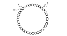
- FIG. 1A and 1B show a structure 1 according to an embodiment of the present invention.
- FIG. 1A is an elevation view of the structure 1
- FIG. 1B is a plan view of the structure 1.
- the structure 1 mainly includes a plurality of steel pipe sheet piles 3 provided on the bottom 5 and a bottom plate 7.
- the steel pipe sheet pile 3 which comprises the structure 1 is arrange
- the joining of the steel pipe sheet piles 3 is performed by a joint 13 provided on the side of the steel pipe sheet pile 3. Since the joint 13 is watertight, water within a range surrounded by the plurality of steel pipe sheet piles 3 can be discharged.
- a bottom plate 7 is provided on the inner lower surface surrounded by the steel pipe sheet pile 3.
- the bottom plate 7 is made of concrete, for example.
- the shape of the structure 1 formed by the steel pipe sheet pile 3 is not limited to a circle, and may be another shape such as a rectangle. Further, in the following description, a portion provided at a position deeper than the bottom 5 of the steel pipe sheet pile 3 is referred to as a bottom bottom 9, and a portion above the bottom 5 is referred to as a bottom top 11.
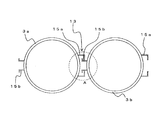
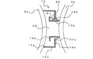
- FIG. 2A and 2B show the joint 13.
- FIG. 2A is a view showing between the steel pipe sheet piles 3a and 3b
- FIG. 2B is an enlarged view of a portion A in FIG. 2A.
- L-shaped members 15a and 15b are provided on both sides of the steel pipe sheet piles 3a and 3b along the axial directions of the steel pipe sheet piles 3a and 3b.
- a pair of L-shaped members 15a is provided on one side (right side in the figure) of the steel pipe sheet piles 3a and 3b.
- a pair of L-shaped members 15b are provided on the other side (left side in the figure) of the steel pipe sheet piles 3a and 3b. That is, the L-shaped members 15a and 15b are provided on the substantially opposite sides of the steel pipe sheet piles 3a and 3b. As the L-shaped members 15a and 15b, section steel having an L-shaped cross section may be used.
- the L-shaped member 15a is a plate-shaped member that is bent in an L-shape, and is provided toward the connecting direction of adjacent steel pipe sheet piles (right side in the figure).
- the pair of L-shaped members 15a includes a base portion 17a provided substantially parallel to each other, and an arm portion 19a bent substantially vertically toward each other at the distal end portion of the base portion 17a.
- the L-shaped member 15b is a plate-shaped member that is bent into an L-shape, and is provided toward the connecting direction of adjacent steel pipe sheet piles (left side in the figure).
- the pair of L-shaped members 15b includes a base portion 17b provided substantially parallel to each other, and an arm portion 19b bent substantially perpendicularly toward each other at the distal end portion of the base portion 17b.
- a hole 21 is provided in a part of the base portion 17b of the L-shaped member 15b.
- the base portions 17a and 17b of the L-shaped members 15a and 15b are joined to predetermined positions of the steel pipe sheet piles 3a and 3b by welding or the like.
- the pair of L-shaped members 15a and the pair of L-shaped members 15b of the steel pipe sheet piles 3a and 3b to be joined are provided to face each other.
- the base portions 17b of the pair of L-shaped members 15b are disposed between the tips of the arm portions 19b of the pair of L-shaped members 15a, and the arm portions 19b of the L-shaped member 15b are in a space surrounded by the pair of L-shaped members 15a. It will fit.
- the second steel pipe sheet pile for example, the steel pipe sheet pile 3b
- the second steel pipe sheet pile is installed from above the existing steel pipe sheet pile. What is necessary is just to insert from upper direction so that L-shaped members may mesh.
- the space surrounded by the L-shaped members 15a, 15b and the steel pipe sheet piles 3a, 3b is filled with concrete 23.
- the filling of the concrete 23 ensures the water tightness of the joint 13 and ensures the strength of the joint.
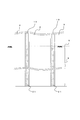
- FIG. 3 is a lower enlarged view of the structure 1 and shows the steel pipe sheet pile 3 provided in the bottom 9 of the water bottom.
- the steel pipe sheet pile 3 is provided on the bottom 5. Therefore, the lower part (bottom bottom 9) of the steel pipe sheet pile 3 is buried in the bottom 5.
- a plurality of holes 21 are provided at predetermined intervals in the base portion 17b of the L-shaped member 15b. That is, the hole 21 is provided at least in the base portion 17b of the L-shaped member 15b located in the bottom 9 of the water bottom.
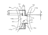
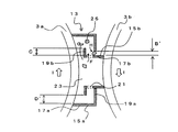
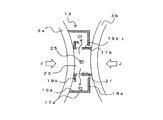
- FIG. 4A and 4B are cross-sectional views including the hole 21 in the joint 13.
- FIG. 4A is a diagram showing a state in which the steel pipe sheet piles 3a and 3b are provided at straight positions (that is, a state in which the L-shaped members 15a and 15b are provided without being in contact with each other).
- FIG. 4B shows a state in which the steel pipe sheet piles 3a and 3b are displaced from each other in a direction substantially perpendicular to the connection direction (that is, a state in which the end portion of the L-shaped member 15a is provided in contact with the L-shaped member 15b).
- FIG. 4A is a diagram showing a state in which the steel pipe sheet piles 3a and 3b are provided at straight positions (that is, a state in which the L-shaped members 15a and 15b are provided without being in contact with each other).
- FIG. 4B shows a state in which the steel pipe sheet piles 3a and 3b are displaced from each other in a direction substantially perpen
- the inside of the joint 13 is filled with the concrete 23 including the aggregate 25.
- the aggregate 25 can use various crushed stones.
- a natural aggregate such as sea sand or an artificial aggregate such as blast furnace slag may be used as the aggregate 25.
- the aggregate 25 is, for example, a coarse aggregate (an aggregate that uses a 5 mm sieve and remains at 85% or more by weight), and the size of the grains is preferably about 20 mm, for example.
- the grain size of the aggregate 25 represents the approximate maximum dimension of the coarse aggregate.
- the particle size of the aggregate 25 is 20 mm.
- the weight percentage of particles passing through the sieve is 90 to 100% by the sieve having a nominal size of 20 mm. It shows that there is. That is, the size of the coarse aggregate grains includes grains of about 5 to 20 mm.
- the size of the aggregate 25 in the present invention is the above-mentioned JIS of the aggregate mainly included in the concrete. Refers to the grain size defined by. For example, when the coarse aggregate A having a coarse grain ratio or an actual performance ratio of 50% or more is included, even if other fine aggregates or fine grains are contained, the grain of the coarse aggregate A is JIS Refers to the indicated size.
- 4A and 4B only a part of the aggregate 25 is shown.
- 4A and 4B show a state before the concrete 23 is consolidated, and the aggregate 25 can be freely moved inside the joint 13.
- C needs to be larger than B 'in the state of FIG. 4B where the positions of the steel pipe sheet piles are most displaced.
- the movement route of the aggregate 25 is sufficiently large with respect to the size of the aggregate 25. There is a need. This is because if the moving route is smaller than the aggregate 25, the route is blocked by the aggregate 25 and the filling of the concrete 23 is prevented.
- the movement route of the aggregate 25 includes, for example, a gap (in the direction of arrow G in the figure) from the tip of the arm portion 19b of the L-shaped member 15b to the inner surface of the base portion 17a of the L-shaped member 15a.
- a gap in the direction of arrow G in the figure
- D ′ is sufficiently larger than d.
- D ′ is twice or more than d, it is desirable that the aggregate 25 is not clogged at this position and does not hinder the flow of the concrete 23.
- the gap between the tip of the arm portion 19a of the L-shaped member 15a and the outer surface of the base portion 17b of the L-shaped member 15b is B 'at the maximum.
- the gap is larger than the size d of the aggregate 25, the aggregate 25 (concrete 23) flows out from the gap.
- the concrete 23 flows out into the water. Therefore, water is polluted. For this reason, it is necessary to prevent the leakage of the concrete 23 from this gap.
- B ′ is preferably smaller than d. In other words, it is desirable that B is smaller than approximately 1 ⁇ 2 of d.
- FIG. 5A is a diagram showing a state in which the steel pipe sheet pile 3b is provided at a position closest to the steel pipe sheet pile 3a side
- FIG. 5B is a drawing in which the steel pipe sheet pile 3b is provided at a position farthest away from the steel pipe sheet pile 3a. It is a figure which shows a state.
- the aggregate 25 is clogged in the gap between the tip of the L-shaped member 15a (arm portion 19a) and the outer surface of the base portion 17b of the L-shaped member 15b. For this reason, the outflow of the concrete 23 from this clearance gap is suppressed.
- the base portion 17b is exposed to the outside of the arm portion 19a.
- the hole 21 allows the outside and the inside of the joint 13 to communicate with each other. Therefore, the concrete 23 including the aggregate 23 may flow out through the hole 21 (in the direction of arrow M in the figure).
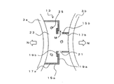
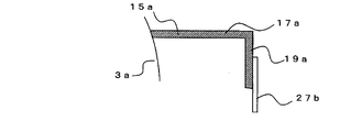
- FIG. 6A, FIG. 6B, and FIG. 6C are views showing a state in which a seal member is provided on the arm portion 19a.
- a seal member 27a is provided on the outer surface of the arm portion 19a so as to extend toward the distal end of the arm portion 19a.
- the seal member 27a is a material that can be elastically plastically deformed.
- a metal such as a thin steel plate or a resin such as rubber can be used.
- the seal member is provided in a range from the upper side of the steel pipe sheet pile 3 to at least the upper bottom 11 (FIG. 1A). This is because, in the lower water bottom portion 9 (FIG. 1A), the surrounding earth and sand plays a role of a sealing member as described above.
- the sealing member 27a may be curved in advance.
- the seal member 27b may be provided straight with respect to the arm portion 19a. In any case, the seal member can be deformed in contact with the base portion 17b on the steel pipe sheet pile 3b side to be joined, thereby closing the gap between the arm portion 19a and the base portion 17b. In the following description, an example using the seal member 27a will be described.
- FIG. 6C is a diagram showing a state in which the steel pipe sheet piles 3a and 3b are connected.
- the arm portion 19a of the pair of L-shaped members 15a is provided with a seal member 27a protruding from the arm portion 19a in the inner direction.
- the tip of the seal member 27a contacts the outer surface of the base portion 17b of the steel pipe sheet pile 3b to be joined. Since the seal member 27a can be elasto-plastically deformed, the seal member 27a also follows the displacement of the steel pipe sheet piles 3a and 3b (displacement as shown in FIG. 4B), and the gap between the arm portion 19a and the base portion 17b is closed. Therefore, even if the gap between the arm portion 19a and the base portion 17b is closed by the aggregate 25, the concrete 23 that flows out slightly (in the direction of arrow O in the figure) can be more reliably prevented.
- FIG. 7A shows the L-shaped member 15a in a state where the seal member 27a is provided.
- 7A is a front view seen from the joining direction side of the L-shaped member 15a
- FIG. 7B is a cross-sectional view taken along line PP in FIG. 7A
- FIG. 7C is a cross-sectional view taken along line QQ in FIG.
- the seal member 27 a is provided along the L-shaped member 15 a in the axial direction of the steel pipe sheet pile 3.
- a tapered portion 29 is provided above the seal member 27a.
- the tapered portion 29 is formed so that the distance between the tips of the pair of seal members 27a increases upward. That is, a tapered portion 29 is formed above the seal member 27a so that the width (horizontal direction length) of the seal member 27a gradually decreases upward.
- the horizontal length of the seal member 27a is short near the upper end of the steel pipe sheet pile 3b.
- the seal member 27a provided on the outer surface of the arm portion 19a does not protrude from the tip end of the arm portion 19a in the vicinity of the upper end, and the interval between the pair of arm portions 19a is ensured. That is, in FIG. 7B, the L-shaped member 15b to be joined is illustrated by a dotted line, but the base portion 17b of the L-shaped member 15b does not contact the seal member 27a but contacts the arm portion 19a.
- the seal member 27a does not contact the L-shaped member 15b. For this reason, the insertability of the L-shaped member 15b is not affected, and the workability is excellent.
- the seal member 27a is below the taper portion 29 of the seal member 27a (the portion located below the water surface) by a length sufficient for the seal member 27a to close the gap from the tip of the arm portion 19a. It protrudes and contacts the base 17b. For this reason, the gap between the arm portion 19a and the base portion 17b is closed by the seal member 27a. Therefore, concrete does not flow out of this gap.
- the hole 21 is provided only in the lower water bottom 9 and the seal member 27a is provided only in the upper water bottom 11.
- the sealing member 27a may be provided up to the bottom bottom 9, and the hole 21 may be formed in the bottom top 11. Even if the hole 21 is formed in the upper water bottom 11, leakage of the concrete can be prevented by making the size of the hole 21 smaller than the size of the aggregate 25 or combining it with the seal member 27a.
- the steel pipe sheet piles can be easily joined to each other, the concrete filling property is excellent, and the concrete can be reliably prevented from flowing out into water. Moreover, since the cross-sectional area enclosed by the L-shaped members 15a and 15b is large, a high shear strength can be obtained at the joint.
- the steel pipe sheet piles 3a and 3b are joined by the joint 13 using the L-shaped members 15a and 15b, for example, a pair of L-shaped members 15b may be inserted between the pair of L-shaped members 15a.
- the concrete 23 as the filler includes an aggregate 25, and the gap between the tip of the arm portion 19 a of the L-shaped member 15 a and the outer surface of the base portion 17 b of the L-shaped member 15 b is smaller than the size of the aggregate 25. For this reason, the aggregate 25 is clogged in this gap, and further outflow of the concrete 23 can be suppressed.
- the gap between the distal end of the arm portion 19b of the L-shaped member 15b and the inner surface of the base portion 17a of the L-shaped member 15a is sufficiently large with respect to the size of the aggregate 25. For this reason, the concrete 23 is reliably filled in the space between the L-shaped members 15a and 15b.
- the concrete 23 enters the hole 21, and the adhesion strength between the concrete 23 and the L-shaped member 15b can be increased. For this reason, a high shear strength can be obtained at the joint. Further, since the size of the hole 21 is sufficiently larger than the size of the aggregate 25, the concrete 23 passes through the hole 21 when the concrete 23 is placed in the space between the L-shaped members 15a and 15b. . For this reason, the concrete 23 can be more reliably filled into the space.
- the sealing member 27a when the sealing member 27a is provided in the water bottom upper part 11, the outflow of the concrete 23 from the clearance gap between the arm part 19a front-end
- the seal member 27a has the taper portion 29 at the top, the seal member 27a does not hinder the insertion when the L-type member 15b is inserted into the L-type member 15a. For this reason, the L-shaped member 15 b can be inserted along the tapered portion 29.
- the adhesion strength between the concrete 23 and the L-shaped members 15a and 15b is improved. Accordingly, the shear strength of the joint is improved.
- connection structure for joining the steel pipe sheet piles is the first steel pipe sheet pile, the second steel pipe sheet pile adjacent to the first steel pipe sheet pile, the first arm portion, and the first base portion.
- a concrete portion including an aggregate placed in a space surrounded by an L-shaped member and the pair of second L-shaped members, and the gap between the first arm portion and the second base portion is The clearance between the second arm portion and the first base portion is smaller than the size of the aggregate particles, and the aggregate
- a plurality of holes may be provided at predetermined intervals in the axial direction on at least a part of the side surface of the second L-shaped member.
- the size of the hole may be twice or more the size of the aggregate grain.
- a seal member that extends toward the second L-shaped member and contacts the second L-shaped member may be provided on at least a part of the first arm portion. Further, the seal member may have a tapered portion whose width gradually increases downward from the upper end of the first L-shaped member.
- the first L-shaped member and the second L-shaped member have a contact surface that contacts the concrete portion, and at least one of the first L-shaped member and the second L-shaped member. Irregularities may be formed on the contact surface.
Landscapes
- Engineering & Computer Science (AREA)
- Structural Engineering (AREA)
- Chemical & Material Sciences (AREA)
- Composite Materials (AREA)
- Life Sciences & Earth Sciences (AREA)
- General Life Sciences & Earth Sciences (AREA)
- Mining & Mineral Resources (AREA)
- Paleontology (AREA)
- Civil Engineering (AREA)
- General Engineering & Computer Science (AREA)
- Bulkheads Adapted To Foundation Construction (AREA)
Abstract
Description
本願は、2009年6月19日に、日本に出願された特願2009-146271号に基づき優先権を主張し、その内容をここに援用する。
(1)本発明の第一の態様は、鋼管矢板同士の接続構造であって、第1鋼管矢板の側方に互いに内方に向けて接合された一対の第1のL型部材と、前記第1鋼管矢板と隣り合う第2鋼管矢板の側方に、前記第1のL型部材と対向するように設けられ、互いに外方に向けて接合された一対の第2のL型部材と、を具備する。
一対の前記第2のL型部材は、一対の前記第1のL型部材の内部に配設され、一対の前記第1のL型部材および一対の前記第2のL型部材とで囲まれた空間には骨材を含むコンクリートが打設され、前記第1のL型部材の先端と前記第2のL型部材との隙間は、前記骨材の粒の大きさよりも小さく、前記第2のL型部材の先端と前記第1のL型部材との隙間は、前記骨材の粒の大きさの2倍以上である。
(2)上記(1)に記載の鋼管矢板同士の接続構造では、前記第2のL型部材の少なくとも一部の側面には、軸方向に所定間隔で複数の孔が設けられてもよい。
(3)上記(2)に記載の鋼管矢板同士の接続構造では、前記孔の大きさは、前記骨材の粒の大きさの2倍以上であってもよい。
(4)上記(1)~(3)のいずれか1項に記載の鋼管矢板同士の接続構造では、前記第1のL型部材の先端部近傍の少なくとも一部には、前記第2のL型部材側に向けて延在する、前記第2のL型部材と接触可能なシール部材が設けられてもよい。
(5)上記(4)に記載の鋼管矢板同士の接続構造では、前記シール部材は、前記第1のL型部材の上端から下方に向けて徐々に幅が大きくなるテーパ部を有してもよい。
(6)上記(1)~(5)に記載の鋼管矢板同士の接続構造では、前記第1のL型部材および/または前記第2のL型部材の前記コンクリートの接触面には凹凸が形成されてもよい。
(7)本発明の第二の態様は、複数の鋼管矢板が略鉛直方向に水中に設置され、鋼管矢板同士が継手で接合された構造体である。第1鋼管矢板の側方に互いに内方に向けて接合された一対の第1のL型部材と、前記第1鋼管矢板と隣り合う第2鋼管矢板の側方に、前記第1のL型部材と対向するように設けられ、互いに外方に向けて接合された一対の第2のL型部材とを具備する接続構造を用い、一対の前記第2のL型部材は、一対の前記第1のL型部材に嵌りこみ、一対の前記第1のL型部材および一対の前記第2のL型部材とで囲まれた空間には骨材を含むコンクリートが打設され、前記第1のL型部材の先端と前記第2のL型部材との隙間は、前記骨材の粒の大きさよりも小さく、前記第2のL型部材の先端と前記第1のL型部材との隙間は、前記骨材の粒の大きさの2倍よりも大きく、前記接続構造の、少なくとも水底下への埋設部においては、前記第2のL型部材側面に軸方向に所定間隔で孔が設けられ、前記継手構造の、少なくとも水底よりも上方部においては、前記第1のL型部材の外方先端部近傍に前記第2のL型部材側に向けて延在する、前記第2のL型部材と接触可能なシール部材が設けられる構造体である。
(8)上記(7)に記載の構造体では、前記第1のL型部材および/または前記第2のL型部材の前記コンクリートの接触面には凹凸が形成されてもよい。
上記(2)に記載の構成によれば、第2のL型部材の一部に複数の孔を設けることにより、孔を通じてコンクリートが流れるため、L型部材同士の接続構造内部に、確実にコンクリートを充填することができる。また、孔にコンクリートが入りこむことでコンクリートとL型部材との付着強度が向上する。
上記(3)に記載の構成によれば、孔の大きさが骨材の粒の大きさの2倍以上であるため、より確実にコンクリートを充填することができる。
上記(4)に記載の構成によれば、第1のL型部材の先端部近傍の一部に、第2のL型部材側に向けて、第2のL型部材と接触可能なシール部材が設けられるため、L型部材同士の隙間からコンクリートが漏れだすことをより確実に防止することができる。
上記(5)に記載の構成によれば、第1のL型部材の上端から下方に向けて徐々にシール部材の幅が大きくなるテーパ部を設けることで、隣接する鋼管矢板の第2のL型部材を容易に挿入することができる。このため作業が容易である。
上記(6)に記載の構成によれば、第1のL型部材および/または第2のL型部材のコンクリートの接触面に凹凸が形成されるため、コンクリートとの付着強度が増加して、より強固な接続構造を得ることができる。
上記(7)に記載の構成によれば、簡易な構造で施工性に優れ、強度の高い構造体を得ることができる。特に、一対のL型部材で接続構造が構成されるため、施工性に優れ、水底より下の部分に位置する第2のL型部材に孔を設けることで、コンクリートの充填性を高めるとともに、コンクリートとL型部材との付着強度を高めることができる。孔が外方に露出する場合であっても、水底下であれば、それ以上コンクリートが流出することがなく、水の汚濁の問題もない。
また、水底より上の部分にはシール部材が設けられるため、骨材によって隙間が埋められてもなお残るわずかな隙間からのコンクリートの流出を確実に抑えることができ、水の汚濁を防止することができる。
上記(8)に記載の構成によれば、第1のL型部材および/または第2のL型部材のコンクリート接触面に凹凸が形成されるため、コンクリートに対する付着強度が増加して、より強固な接続構造を有する構造体を得ることができる。
前記第2のL型部材の少なくとも一部の側面には、軸方向に所定間隔で複数の孔が設けられてもよい。
また、前記孔の大きさは、前記骨材の粒の大きさの2倍以上であってもよい。
また、前記第1アーム部の少なくとも一部には、前記第2のL型部材側に向けて延在し、前記第2のL型部材と接触するシール部材が設けられていてもよい。
また、前記シール部材は、前記第1のL型部材の上端から下方に向けて徐々に幅が大きくなるテーパ部を有してもよい。
また、前記第1のL型部材および前記第2のL型部材は、前記コンクリート部に接触する接触面を有し、前記第1のL型部材および前記第2のL型部材の少なくとも一方の前記接触面には、凹凸が形成されていてもよい。
3、3a、3b 鋼管矢板
5 水底
7 底版
9 水底下部
11 水底上部
13 継手
15a、15b L型部材
17a、17b 基部
19a、19b アーム部
21 孔
23 コンクリート
25 骨材
27a、27b シール部材
29 テーパ部
Claims (8)
- 第1鋼管矢板の側方に互いに内方に向けて接合された一対の第1のL型部材と、
前記第1鋼管矢板と隣り合う第2鋼管矢板の側方に、前記第1のL型部材と対向するように設けられ、互いに外方に向けて接合された一対の第2のL型部材と、
を具備し、
一対の前記第2のL型部材は、一対の前記第1のL型部材の内部に配設され、
一対の前記第1のL型部材および一対の前記第2のL型部材とで囲まれた空間には骨材を含むコンクリートが打設され、
前記第1のL型部材の先端と前記第2のL型部材との隙間は、前記骨材の粒の大きさよりも小さく、
前記第2のL型部材の先端と前記第1のL型部材との隙間は、前記骨材の粒の大きさの2倍以上である
ことを特徴とする鋼管矢板同士の接続構造。 - 前記第2のL型部材の少なくとも一部の側面には、軸方向に所定間隔で複数の孔が設けられる
ことを特徴とする請求項1記載の鋼管矢板同士の接続構造。 - 前記孔の大きさは、前記骨材の粒の大きさの2倍以上である
ことを特徴とする請求項2記載の鋼管矢板同士の接続構造。 - 前記第1のL型部材の先端部近傍の少なくとも一部には、前記第2のL型部材側に向けて、前記第2のL型部材と接触可能なシール部材が設けられる
ことを特徴とする請求項1から請求項3のいずれか一項に記載の鋼管矢板同士の接続構造。 - 前記シール部材は、前記第1のL型部材の上端から下方に向けて徐々に幅が大きくなるテーパ部を有する
ことを特徴とする請求項4記載の鋼管矢板同士の接続構造。 - 前記第1のL型部材および前記第2のL型部材の少なくとも一方の前記コンクリートの接触面には凹凸が形成される
ことを特徴とする請求項1から請求項3のいずれか一項に記載の鋼管矢板同士の接続構造。 - 複数の鋼管矢板が略鉛直方向に水中に設置され、鋼管矢板同士が継手で接合された構造体であって、
第1鋼管矢板の側方に互いに内方に向けて接合された一対の第1のL型部材と、前記第1鋼管矢板と隣り合う第2鋼管矢板の側方に、前記第1のL型部材と対向するように設けられ、互いに外方に向けて接合された一対の第2のL型部材とを具備する接続構造を用い、
一対の前記第2のL型部材は、一対の前記第1のL型部材に嵌りこみ、
一対の前記第1のL型部材および一対の前記第2のL型部材とで囲まれた空間には骨材を含むコンクリートが打設され、
前記第1のL型部材の先端と前記第2のL型部材との隙間は、前記骨材の粒の大きさよりも小さく、
前記第2のL型部材の先端と前記第1のL型部材との隙間は、前記骨材の粒の大きさの2倍よりも大きく、
前記接続構造の、少なくとも水底下への埋設部においては、前記第2のL型部材側面に軸方向に所定間隔で孔が設けられ、
前記継手構造の、少なくとも水底よりも上方部においては、前記第1のL型部材の外方先端部近傍に前記第2のL型部材側に向けて、前記第2のL型部材と接触可能なシール部材が設けられる
ことを特徴とする構造体。 - 前記第1のL型部材および前記第2のL型部材の少なくとも一方の前記コンクリートの接触面には凹凸が形成されることを特徴とする請求項7記載の構造体。
Priority Applications (2)
| Application Number | Priority Date | Filing Date | Title |
|---|---|---|---|
| CN201080026593.9A CN102803615B (zh) | 2009-06-19 | 2010-06-15 | 钢管板桩彼此的连接构造以及构造体 |
| AU2010261247A AU2010261247B2 (en) | 2009-06-19 | 2010-06-15 | Structure for connecting steel pipe sheet piles, and structure body |
Applications Claiming Priority (2)
| Application Number | Priority Date | Filing Date | Title |
|---|---|---|---|
| JP2009146271A JP5231344B2 (ja) | 2009-06-19 | 2009-06-19 | 鋼管矢板同士の接続構造および構造体 |
| JP2009-146271 | 2009-06-19 |
Publications (1)
| Publication Number | Publication Date |
|---|---|
| WO2010146836A1 true WO2010146836A1 (ja) | 2010-12-23 |
Family
ID=43356168
Family Applications (1)
| Application Number | Title | Priority Date | Filing Date |
|---|---|---|---|
| PCT/JP2010/003971 Ceased WO2010146836A1 (ja) | 2009-06-19 | 2010-06-15 | 鋼管矢板同士の接続構造および構造体 |
Country Status (5)
| Country | Link |
|---|---|
| JP (1) | JP5231344B2 (ja) |
| CN (1) | CN102803615B (ja) |
| AU (1) | AU2010261247B2 (ja) |
| TW (1) | TW201116671A (ja) |
| WO (1) | WO2010146836A1 (ja) |
Cited By (1)
| Publication number | Priority date | Publication date | Assignee | Title |
|---|---|---|---|---|
| CN113216228A (zh) * | 2021-01-13 | 2021-08-06 | 中交第三航务工程局有限公司 | 一种组合桩围堰的施工工艺 |
Families Citing this family (3)
| Publication number | Priority date | Publication date | Assignee | Title |
|---|---|---|---|---|
| CN104775529B (zh) * | 2015-02-16 | 2017-05-17 | 中交一航局第一工程有限公司 | 装配式构件的止水结构及其施工方法 |
| CN112227382A (zh) * | 2020-10-19 | 2021-01-15 | 中建一局集团建设发展有限公司 | 兼具止水功能的双排桩结构及其施工方法 |
| CN113700013A (zh) * | 2021-08-20 | 2021-11-26 | 中建五局土木工程有限公司 | 高喷灌浆与粘土心墙结合的土石围堰防渗施工方法 |
Citations (2)
| Publication number | Priority date | Publication date | Assignee | Title |
|---|---|---|---|---|
| JPS57105331U (ja) * | 1980-12-16 | 1982-06-29 | ||
| JP2004360440A (ja) * | 2003-05-14 | 2004-12-24 | Taisei Rotec Corp | 止水壁継手部の止水方法 |
Family Cites Families (5)
| Publication number | Priority date | Publication date | Assignee | Title |
|---|---|---|---|---|
| JP2001207442A (ja) * | 2000-01-31 | 2001-08-03 | Taiheiyo Cement Corp | 矢 板 |
| JP3747198B2 (ja) * | 2002-12-18 | 2006-02-22 | 株式会社データ・トゥ | 鋼管矢板井筒基礎 |
| JP2004353337A (ja) * | 2003-05-29 | 2004-12-16 | Jfe Steel Kk | 鋼管矢板の継手部材及び継手構造 |
| JP4674052B2 (ja) * | 2004-03-30 | 2011-04-20 | 新日本製鐵株式会社 | 鋼管矢板継手、鋼管矢板の継手構造および鋼管矢板基礎 |
| CN1837512B (zh) * | 2006-04-07 | 2011-04-20 | 上海市政工程设计研究总院 | 一种钢板桩和钢管桩组合围堰及其制作方法 |
-
2009
- 2009-06-19 JP JP2009146271A patent/JP5231344B2/ja not_active Expired - Fee Related
-
2010
- 2010-06-14 TW TW99119262A patent/TW201116671A/zh unknown
- 2010-06-15 CN CN201080026593.9A patent/CN102803615B/zh not_active Expired - Fee Related
- 2010-06-15 WO PCT/JP2010/003971 patent/WO2010146836A1/ja not_active Ceased
- 2010-06-15 AU AU2010261247A patent/AU2010261247B2/en not_active Ceased
Patent Citations (2)
| Publication number | Priority date | Publication date | Assignee | Title |
|---|---|---|---|---|
| JPS57105331U (ja) * | 1980-12-16 | 1982-06-29 | ||
| JP2004360440A (ja) * | 2003-05-14 | 2004-12-24 | Taisei Rotec Corp | 止水壁継手部の止水方法 |
Cited By (1)
| Publication number | Priority date | Publication date | Assignee | Title |
|---|---|---|---|---|
| CN113216228A (zh) * | 2021-01-13 | 2021-08-06 | 中交第三航务工程局有限公司 | 一种组合桩围堰的施工工艺 |
Also Published As
| Publication number | Publication date |
|---|---|
| AU2010261247B2 (en) | 2015-09-24 |
| CN102803615B (zh) | 2014-04-02 |
| JP5231344B2 (ja) | 2013-07-10 |
| CN102803615A (zh) | 2012-11-28 |
| JP2011001767A (ja) | 2011-01-06 |
| AU2010261247A1 (en) | 2012-01-19 |
| TW201116671A (en) | 2011-05-16 |
Similar Documents
| Publication | Publication Date | Title |
|---|---|---|
| WO2010146836A1 (ja) | 鋼管矢板同士の接続構造および構造体 | |
| JP2017179985A (ja) | 排水路形成用薄板部材による排水路及びその排水路の施工方法 | |
| JP4882096B2 (ja) | 遮水壁材の継手充填用注入材及び該注入材を使用した遮水壁の施工方法 | |
| TW200416329A (en) | Steel wall and the manufacture method thereof | |
| CN204785312U (zh) | 中水管道和中水输送系统 | |
| CN202247998U (zh) | 一种地下连续墙接头清理器 | |
| JP2001248152A (ja) | 鋼矢板および鋼矢板継手部の止水構造 | |
| JP3651342B2 (ja) | 鋼矢板継手部の止水構造 | |
| CN115852937A (zh) | 地下连续墙接头及地下连续墙的构筑方法 | |
| CN210315913U (zh) | 一种地漏安装结构 | |
| JP4997424B2 (ja) | 樋管の止水壁構造 | |
| KR200444942Y1 (ko) | 농업용 수로 | |
| CN208236419U (zh) | 一种顶管机出洞穿墙止水环结构 | |
| CN203297826U (zh) | 耐冲刷灰管弯头结构 | |
| CN110468718A (zh) | 一种可周转使用的桥梁泄水孔预埋装置 | |
| KR200351618Y1 (ko) | 시공성이 우수한 관 세척기 | |
| JP2002227187A (ja) | 鋼管矢板の継手およびその施工法 | |
| CN207633209U (zh) | 一种桥梁纵向接缝密封防水结构 | |
| JP3247720U (ja) | 取水用水路ブロック | |
| CN217811171U (zh) | 顶管安装平台 | |
| CN111005326A (zh) | 一种混凝土管涵 | |
| JP2013194355A (ja) | 既設杭の補強構造及び補強方法 | |
| JP2023144800A (ja) | 鋼管矢板壁用継手セットおよびその製造方法ならびに鋼管矢板 | |
| JP3751297B2 (ja) | 護岸の構築方法 | |
| CN101793026B (zh) | 一种搅拌桩止水型压顶梁 |
Legal Events
| Date | Code | Title | Description |
|---|---|---|---|
| WWE | Wipo information: entry into national phase |
Ref document number: 201080026593.9 Country of ref document: CN |
|
| 121 | Ep: the epo has been informed by wipo that ep was designated in this application |
Ref document number: 10789217 Country of ref document: EP Kind code of ref document: A1 |
|
| WWE | Wipo information: entry into national phase |
Ref document number: 2010261247 Country of ref document: AU |
|
| NENP | Non-entry into the national phase |
Ref country code: DE |
|
| ENP | Entry into the national phase |
Ref document number: 2010261247 Country of ref document: AU Date of ref document: 20100615 Kind code of ref document: A |
|
| 122 | Ep: pct application non-entry in european phase |
Ref document number: 10789217 Country of ref document: EP Kind code of ref document: A1 |