WO2010143354A1 - ワークの切断方法 - Google Patents
ワークの切断方法 Download PDFInfo
- Publication number
- WO2010143354A1 WO2010143354A1 PCT/JP2010/003108 JP2010003108W WO2010143354A1 WO 2010143354 A1 WO2010143354 A1 WO 2010143354A1 JP 2010003108 W JP2010003108 W JP 2010003108W WO 2010143354 A1 WO2010143354 A1 WO 2010143354A1
- Authority
- WO
- WIPO (PCT)
- Prior art keywords
- workpiece
- cutting
- wire
- temperature
- slurry
- Prior art date
- Legal status (The legal status is an assumption and is not a legal conclusion. Google has not performed a legal analysis and makes no representation as to the accuracy of the status listed.)
- Ceased
Links
Images




Classifications
-
- B—PERFORMING OPERATIONS; TRANSPORTING
- B28—WORKING CEMENT, CLAY, OR STONE
- B28D—WORKING STONE OR STONE-LIKE MATERIALS
- B28D5/00—Fine working of gems, jewels, crystals, e.g. of semiconductor material; apparatus or devices therefor
- B28D5/04—Fine working of gems, jewels, crystals, e.g. of semiconductor material; apparatus or devices therefor by tools other than rotary type, e.g. reciprocating tools
- B28D5/045—Fine working of gems, jewels, crystals, e.g. of semiconductor material; apparatus or devices therefor by tools other than rotary type, e.g. reciprocating tools by cutting with wires or closed-loop blades
-
- B—PERFORMING OPERATIONS; TRANSPORTING
- B24—GRINDING; POLISHING
- B24B—MACHINES, DEVICES, OR PROCESSES FOR GRINDING OR POLISHING; DRESSING OR CONDITIONING OF ABRADING SURFACES; FEEDING OF GRINDING, POLISHING, OR LAPPING AGENTS
- B24B27/00—Other grinding machines or devices
- B24B27/06—Grinders for cutting-off
- B24B27/0633—Grinders for cutting-off using a cutting wire
Definitions
- the present invention relates to a technique for cutting a workpiece into a wafer by a wire saw.
- a wire saw presses a workpiece against a wire array spirally wound between a plurality of wire guides, and supplies a slurry in which free abrasive grains are mixed with oil-based or water-soluble coolant to the contact portion between the workpiece and the wire.
- it is an apparatus that simultaneously cuts a large number of wafers by the grinding action of loose abrasive grains. Specifically, at the time of reciprocating travel of the wire row, cutting is performed by scraping the workpiece at the bottom of the groove while pressing the free abrasive grains in the supplied slurry against the inner part of the wire groove (cutting groove of the workpiece) with each wire.
- the workpiece is cut into a wafer shape by free abrasive grains being rubbed against the back of the wire groove by the reciprocating wire. Due to the friction generated at this time, the cutting part generates heat, the workpiece is thermally expanded during cutting, and the wire guide is caused by frictional heat with the wire, frictional heat generated at the bearing part that supports the wire guide, etc. Due to thermal expansion, the relative position between the wire array spirally wound around the wire guide and the workpiece was changed during cutting.
- Warp Due to the expansion and contraction of the workpiece, the change in the relative position between the wire row and the workpiece increases, the curvature of the cutting locus drawn on the workpiece also increases, and the Warp deteriorates. As a feature of Warp caused by such a workpiece temperature, the shape in the vicinity of both ends of the workpiece tends to be particularly deteriorated starting from the central portion in the longitudinal direction of the workpiece.
- the present invention has been made in view of the above-described problems, and it is an object of the present invention to provide a workpiece cutting method that can easily and effectively suppress the occurrence of Warp when cutting a cylindrical workpiece with a wire saw.
- a cylindrical workpiece is pressed against a wire row formed by winding a wire spirally between a plurality of wire guides, and the workpiece and the wire are
- the workpiece cutting method of cutting the workpiece into a wafer shape by running the wire while supplying slurry to the contact portion the workpiece is cut before the start of cutting the slurry to be supplied, at a temperature equal to or higher than the temperature.
- a method for cutting a workpiece wherein the workpiece is cut after being heated to a temperature equal to or lower than a maximum temperature of the workpiece reached during the cutting of the workpiece.
- the temperature of the slurry supplied during the cutting of the workpiece can be made constant.
- the cutting method can be easily implemented, and the temperature of the workpiece can be controlled without performing complicated slurry temperature control during cutting.
- the height difference can be reduced to suppress the expansion and contraction of the workpiece, and the effect of improving Warp can be achieved.
- a cylindrical workpiece is pressed against a wire row formed by winding a wire spirally between a plurality of wire guides, and slurry is supplied to a contact portion between the workpiece and the wire.
- the workpiece cutting method for cutting the workpiece into a wafer shape by running the workpiece the workpiece reaches the highest temperature during cutting of the workpiece at a temperature higher than the temperature at which cutting of the supplied slurry is started before the cutting is started. Since the workpiece is cut after being heated to a temperature below the temperature, the rapid temperature change of the workpiece due to the contact between the slurry and the workpiece is suppressed, and the difference in temperature of the workpiece from the start of cutting to the end of cutting is reduced. Therefore, the amount of expansion and contraction of the workpiece can be suppressed, and the generation of Warp can be easily and effectively suppressed.
- Warp generated when a cylindrical workpiece such as a silicon ingot is cut with a wire saw affects not only the quality after cutting but also the quality of the final product. Therefore, with the miniaturization of design rules, improvement in the quality of the cutting shape in cutting a workpiece such as a silicon ingot by a wire saw has been an issue.
- There are various generation factors for such warp there is a warp due to the temperature change of the workpiece. Specifically, the workpiece is caused by contact with the slurry supplied during cutting or generation of frictional heat. This is caused by the expansion and contraction of the workpiece due to the increase in temperature of the workpiece and the decrease in the temperature of the workpiece due to the decrease in the frictional heat generated because the length of the wire entering the workpiece in the latter half of the cutting is reduced.
- Warp caused by such a workpiece temperature
- the shape in the vicinity of both ends of the workpiece tends to deteriorate particularly starting from the central portion in the longitudinal direction of the workpiece.
- the present inventors have conducted intensive studies to solve such problems.
- the maximum temperature of the workpiece being cut does not depend on the temperature of the workpiece at the start of cutting, and if the temperature of the slurry supplied during cutting of the workpiece is constant, the temperature of the workpiece at the time of cutting It was found that the temperature was almost constant at the temperature to which frictional heat was applied. Then, the workpiece is heated to a temperature within the range of the slurry temperature at the start of cutting and the maximum temperature of the workpiece reached during cutting, before the start of cutting. It was conceived that the difference in temperature of the workpiece during cutting can be reduced without causing a change, and as a result, the warp could be greatly improved by suppressing the amount of expansion and contraction of the workpiece, thereby completing the present invention. It was.
- FIG. 1 is a schematic view showing an example of a wire saw that can be used in the workpiece cutting method of the present invention.
- FIG. 2 is a schematic view showing an example of the workpiece feeding mechanism of the wire saw.
- the wire saw 1 mainly includes a wire 2 for cutting the workpiece W, a wire guide 3 for winding the wire 2, a wire tension applying mechanism 4 for applying tension to the wire 2, 4 ′, a workpiece feeding mechanism 5 that feeds a workpiece W to be cut relatively downward, a slurry supply mechanism 6 that supplies slurry at the time of cutting, and the like.
- the wire 2 is unwound from one wire reel 7 and passes through a traverser 8 through a wire tension applying mechanism 4 including a powder clutch (constant torque motor 9), a dancer roller (dead weight) (not shown), and the like.
- a wire row is formed by winding the wire 2 around the wire guide 3.
- the wire 2 is wound around the wire reel 7 ′ through the other wire tension applying mechanism 4 ′.
- the wire guide 3 is a roller in which polyurethane resin is press-fitted around a steel cylinder and grooves are cut on the surface thereof at a constant pitch.
- a wire tension applying mechanism 4 is applied to the wire 2 wound around the wire guide 3.
- the wire 2 can be moved in the reciprocating direction by the driving motor 10 while applying an appropriate tension.
- the workpiece feeding mechanism 5 includes a workpiece holding unit 11, an LM guide 12, and a workpiece feeding main body 13 for pushing down while holding the workpiece W.
- the work W is bonded to the contact plate 14, and the contact plate 14 is held by the work plate 15. Then, the work W is held by the work holding unit 11 through the contact plate 14 and the work plate 15.
- the work W held in this way can be sent out at a feed speed programmed in advance by driving the work holding unit 11 along the LM guide 12 by computer control.
- the workpiece W held by the workpiece holding portion 11 of the workpiece feeding mechanism 5 is thus sent to the wire 2 which is positioned below the workpiece feeding mechanism 5 and reciprocates in the axial direction when cutting.
- the wire 2 is cut and fed downward until the wire 2 reaches the contact plate 14.
- a nozzle 17 is disposed above the wire 2, and when cutting the workpiece W, the slurry can be supplied from the slurry supply mechanism 6 to the contact portion between the workpiece W and the wire 2 through the nozzle 17. It is like that.
- the slurry supply mechanism 6 is connected to a nozzle 17 from a slurry tank 18 via a slurry chiller 16, and the supplied slurry can be supplied from the nozzle 17 with a supply temperature controlled by the slurry chiller 16.
- the workpiece cutting method of the present invention when the wire saw shown in FIG. 1 configured as described above is used will be described below.
- the workpiece W to be cut is held by the workpiece feeding mechanism 5. Further, tension is applied to the wire 2 to reciprocate in the axial direction.
- the workpiece W is heated before starting the cutting of the workpiece W.
- the workpiece W may be heated before the start of cutting, and is not limited to the order of holding the workpiece W, running the wire 2, and the like.
- work W is not specifically limited, For example, it can heat using a thermostat, a hotplate, a warm air type heater, a lamp type heater, etc.
- the temperature at which the workpiece W is heated before the start of cutting is set to be equal to or higher than the temperature at the start of cutting the slurry to be supplied and equal to or lower than the maximum temperature of the workpiece W reached during the cutting of the workpiece W.
- the maximum temperature of the workpiece W can be obtained in advance, for example, by experiments. As described above, when the temperature of the workpiece W to be heated before the start of cutting is set to be equal to or higher than the temperature at the start of cutting of the slurry to be supplied, it is possible to suppress the temperature of the workpiece due to contact between the workpiece and the slurry from rapidly increasing.
- this temperature is set to be equal to or lower than the maximum temperature of the workpiece W reached during the cutting of the workpiece W, it is possible to suppress a rapid decrease in the temperature of the workpiece due to contact between the workpiece and the slurry, and an increase in time for heating. In addition, the economical efficiency and workability of electric power for heating are not deteriorated.
- the temperature of the workpiece W can be measured by providing thermocouples on both end faces in the longitudinal direction of the workpiece W, for example, as shown in FIG. And the average value of the temperature measured with both these thermocouples can be made into the temperature of the workpiece
- the workpiece W held by the workpiece feeding mechanism 5 is relatively lowered, and the workpiece W is pressed against a wire row formed by winding the wire 2 in a spiral shape between the plurality of wire guides 3.
- the slurry is supplied to the contact portion between the workpiece W and the wire 2 by the slurry supply mechanism 6.
- the temperature of the slurry to be supplied can be controlled to a desired temperature by the slurry chiller 16 and can be, for example, 15 ° C. to 30 ° C., but is not particularly limited thereto.
- the kind of slurry to be used is not particularly limited, and the same type as that of the conventional one can be used.
- GC silicon carbide
- abrasive grains dispersed in a liquid can be used.
- the workpiece W is cut and fed into the wire row to cut the workpiece W into a wafer shape. Then, the workpiece W is cut and fed until the wire 2 reaches the contact plate 14, and the cutting of the workpiece W is completed. Thereafter, the cut workpiece W can be pulled out from the wire row by reversing the feeding direction of the workpiece W.
- the magnitude of the tension applied to the wire 2, the traveling speed of the wire 2, and the like can be set as appropriate.
- the traveling speed of the wire can be set to 400 to 800 m / min.
- disconnection can be about 60 s, for example. However, these conditions are not limited to this.
- the workpiece W is heated to a temperature within the range of the temperature at the start of cutting of the slurry to be supplied and the maximum temperature of the workpiece W reached during the cutting of the workpiece W before the cutting starts, and then the workpiece W is cut
- the slurry and the workpiece are in contact with each other, it is possible to suppress a sudden change in the temperature of the workpiece due to the temperature difference between the two, and the maximum temperature of the workpiece W reached during cutting is the maximum temperature of the workpiece W at the start of cutting. Since it does not depend on the temperature, the difference in temperature of the workpiece W from the start of cutting to the end of cutting can be reduced, and the amount of expansion and contraction of the workpiece W can be suppressed.
- the workpiece W is pushed down and cut and fed.
- the workpiece W may be sent out by pushing the wire row upward.
- the temperature of the slurry supplied during the cutting of the workpiece can be made constant.
- the maximum temperature of the workpiece being cut does not depend on the temperature of the workpiece at the start of cutting, and if the temperature of the slurry supplied during cutting of the workpiece is constant It has been discovered that the frictional heat at the time of cutting is added to the temperature of this slurry, and it becomes almost constant.
- the temperature of the workpiece W to be heated before the start of cutting can be easily set according to the maximum temperature obtained, and Warp can be easily suppressed without performing complicated slurry temperature control during cutting. A cutting method that can be performed.
- the workpiece cutting method of the present application does not exclude the control to change the temperature of the slurry being cut. That is, in addition to heating before the start of cutting, the temperature difference of the workpiece W being cut can be reduced more accurately by controlling the temperature of the slurry being cut to be changed. You can also.
- Example 1 Using a wire saw as shown in FIG. 1, a cylindrical silicon ingot having a diameter of 300 mm and a length of 200 mm was cut into a wafer under the cutting conditions shown in Table 1.
- the temperature of the workpiece W to be heated before the start of cutting was set to 24.2 ° C., and the temperature of the slurry was controlled to be constant during cutting at 24 ° C.
- the temperature of the workpiece from the start of cutting to the completion of cutting was measured, and the warp of the cut wafer was evaluated.
- the temperature of the workpiece was measured with thermocouples provided on both end faces of the workpiece, and an average value of the measured temperatures was adopted.
- FIG. 5 shows a Warp shape of a cross section in the feed direction of the workpiece.
- Warp due to the temperature of the workpiece appears prominently at both ends of the workpiece. Therefore, in FIG. 5, a part of one end of the workpiece is extracted. Specifically, from the Warp measurement data, 1 on the new wire supply side of the wire is extracted. The data of 11 wafers extracted every 5 wafers from the first wafer is shown. As shown in FIG. 5, it can be seen that, compared with the results of Comparative Examples 1 and 2 to be described later, the curvature in the vicinity of the end of the workpiece is suppressed and a good Warp shape is obtained.
- the workpiece cutting method of the present application can reduce the difference in the temperature of the workpiece from the start of cutting to the end of cutting, thereby suppressing the expansion and contraction amount of the workpiece, and easily and effectively generating Warp. It was confirmed that it could be suppressed.
- Example 2 A silicon ingot was cut into a wafer under the same conditions as in Example 1 except that the temperature of the workpiece W heated before the start of cutting was 28 ° C., and evaluated in the same manner as in Example 1. The result of the measured temperature is shown in FIG. As shown in FIG. 4, the maximum temperature of the workpiece during cutting is 38.9 ° C., and compared with Comparative Examples 1 and 2 and Example 1 described later, there is a difference in the temperature of the workpiece from the start of cutting to the end of cutting. It turned out that it was reduced. Moreover, the average value of Warp of the whole wafer after cutting was 5.2 ⁇ m, which was a better value than that of Example 1, which was 27% improved from Comparative Example 1 described later.
- FIG. 6 shows a Warp shape in the same manner as in the first embodiment. As shown in FIG. 6, it can be seen that the curvature in the vicinity of the end portion of the workpiece is further suppressed as compared with the result of Example 1, and a good Warp shape is obtained.
- Example 1 The silicon ingot was cut under the same conditions as in Example 1 except that the cutting was started without heating the workpiece W before the cutting was started, and evaluation was made in the same manner as in Example 1.
- the result of the measured temperature is shown in FIG.
- the workpiece W before the start of cutting is 20.4 ° C.
- the maximum temperature of the workpiece during cutting is 39.2 ° C., which is almost the same as in Example 1, from the start of cutting to the end of cutting. It was found that the difference in temperature of the workpiece was larger than that in Example 1 and Example 2.
- the average value of Warp of the whole wafer after cutting is 7.1 ⁇ m, which is worse than that of Example 1 and Example 2.
- FIG. 7 shows the Warp shape in the same manner as in the first embodiment. As shown in FIG. 7, it can be seen that the vicinity of the end portion of the workpiece is strongly curved, causing the Warp to deteriorate.
- Example 2 The silicon ingot is cut under the same conditions as in Example 1 except that the workpiece W is heated to 39.7 ° C., which is higher than the maximum temperature of the workpiece being cut, before cutting is started, and cutting is started. Evaluation was performed in the same manner as in Example 1. At this time, the maximum temperature of the workpiece during cutting was 39.2 ° C., which was almost the same as in Example 1. Note that the expected maximum temperature of the workpiece during cutting was obtained in advance by experiments. The result of the measured temperature is shown in FIG. As shown in FIG. 4, it can be seen that the temperature of the workpiece W rapidly decreases due to contact with the slurry after the start of cutting, and the workpiece temperature is rapidly reversed in the vicinity of the cutting position of 50 mm. Moreover, it turned out that the average value of Warp of the whole wafer after a cutting
- FIG. 8 shows a Warp shape in the same manner as in the first embodiment.
- the influence of the rapid decrease in the workpiece temperature as shown in FIG. 4 appears in the cut surface shape of the wafer, causing the Warp to deteriorate.
- the temperature at which the workpiece W is heated before the start of cutting needs to be equal to or higher than the temperature at the start of cutting of the slurry to be supplied and lower than the maximum temperature of the workpiece reached during the cutting of the workpiece. is there.
- the present invention is not limited to the above embodiment.
- the above-described embodiment is an exemplification, and the present invention has any configuration that has substantially the same configuration as the technical idea described in the claims of the present invention and that exhibits the same effects. Are included in the technical scope.
Landscapes
- Engineering & Computer Science (AREA)
- Mechanical Engineering (AREA)
- Processing Of Stones Or Stones Resemblance Materials (AREA)
- Finish Polishing, Edge Sharpening, And Grinding By Specific Grinding Devices (AREA)
- Mechanical Treatment Of Semiconductor (AREA)
Abstract
本発明は、複数のワイヤガイド間に螺旋状にワイヤを巻回することによって形成されるワイヤ列に円柱状のワークを押圧し、前記ワークとワイヤとの接触部にスラリを供給しながら前記ワイヤを走行させることによって、前記ワークをウェーハ状に切断するワークの切断方法において、切断開始前に前記ワークを、前記供給するスラリの切断開始時の温度以上、前記ワークの切断中に達するワークの最高温度以下の温度に加温してから該ワークを切断することを特徴とするワークの切断方法である。これにより、ワイヤソーによる円柱状のワークの切断において、Warpの発生を簡単に効果的に抑制することができるワークの切断方法が提供される。
Description
本発明は、ワイヤソーによってワークをウェーハ状に切断する技術に関する。
ワイヤソーとは、複数本のワイヤガイド間に螺旋状に巻回されたワイヤ列にワークを押圧し、ワークとワイヤとの接触部に油性又は水溶性のクーラントに遊離砥粒を混入したスラリを供給することにより、遊離砥粒の研削作用によって同時に多数枚のウェーハに切断する装置である。具体的には、ワイヤ列の往復走行時に、供給されたスラリ中の遊離砥粒を、各ワイヤによりワイヤ溝(ワークの切断溝)の奥部に押しつけながら溝底部のワークを削り取ることによって切断する。
このようにワークは、往復走行するワイヤによりワイヤ溝の奥部に遊離砥粒が擦りつけられることにより、ウェーハ状に切断される。この際に発生する摩擦により、切断部が発熱することによって、ワークは切断中に熱膨張し、また、ワイヤガイドはワイヤとの摩擦熱やワイヤガイドを支承するベアリング部で発生する摩擦熱等による熱膨張により軸方向に伸び、このためワイヤガイドに螺旋状に巻回されたワイヤ列とワークとの相対位置が切断中に変化していた。
これらワークの熱膨張や、ワイヤガイドの軸方向の伸びによるワイヤ列とワークとの相対位置の変化は、ワイヤによりワークに描かれる切断軌跡を湾曲させ、この切断軌跡の湾曲が、ウェーハ加工後の形状測定においてWarpとして検出される問題があった。
上記した切断時の摩擦熱が変動することによって、ウェーハの温度が変動して、ウェーハ表面にうねりが生じるという問題に対して、ワイヤとウェーハとが同時に接触している長さ2Lとワイヤ列数pとの積に応じた熱量を供給するスラリから吸熱することにより、ウェーハの切断部の温度を略一定に保つことでうねりを抑制するとされるワイヤソー切断方法が開示されている(特許文献1参照)。
上記した切断時の摩擦熱が変動することによって、ウェーハの温度が変動して、ウェーハ表面にうねりが生じるという問題に対して、ワイヤとウェーハとが同時に接触している長さ2Lとワイヤ列数pとの積に応じた熱量を供給するスラリから吸熱することにより、ウェーハの切断部の温度を略一定に保つことでうねりを抑制するとされるワイヤソー切断方法が開示されている(特許文献1参照)。
しかし、このような切断方法を実施するためには、追加の装置と複雑な制御が必要であり、製造コストも高くなってしまう。
また、ワークが円柱状のインゴットである場合、切断開始時においてはワークに侵入するワイヤ長が短いため発生する摩擦熱は低く、ワーク温度も低いが、切断の進行とともにワークに侵入するワイヤ長が長くなり、発生する摩擦熱が増加してワークは膨張する。一方、切断後半部ではワークに侵入するワイヤ長が縮小するため発生する摩擦熱が低下し、ワーク温度も低下するためワークは収縮する。
また、ワークが円柱状のインゴットである場合、切断開始時においてはワークに侵入するワイヤ長が短いため発生する摩擦熱は低く、ワーク温度も低いが、切断の進行とともにワークに侵入するワイヤ長が長くなり、発生する摩擦熱が増加してワークは膨張する。一方、切断後半部ではワークに侵入するワイヤ長が縮小するため発生する摩擦熱が低下し、ワーク温度も低下するためワークは収縮する。
このワークの膨張収縮によりワイヤ列とワークとの相対位置の変化が大きくなり、ワークに描かれる切断軌跡の湾曲も大きくなり、Warpが悪化してしまう。
このようなワーク温度に起因したWarpの特徴として、ワークの長手方向の中央部を起点としてワークの両端近傍の形状が特に悪化する傾向にある。
このようなワーク温度に起因したWarpの特徴として、ワークの長手方向の中央部を起点としてワークの両端近傍の形状が特に悪化する傾向にある。
本発明は前述のような問題に鑑みてなされたもので、ワイヤソーによる円柱状のワークの切断において、Warpの発生を簡単に効果的に抑制することができるワークの切断方法を提供することを目的とする。
上記目的を達成するために、本発明によれば、複数のワイヤガイド間に螺旋状にワイヤを巻回することによって形成されるワイヤ列に円柱状のワークを押圧し、前記ワークとワイヤとの接触部にスラリを供給しながら前記ワイヤを走行させることによって、前記ワークをウェーハ状に切断するワークの切断方法において、切断開始前に前記ワークを、前記供給するスラリの切断開始時の温度以上、前記ワークの切断中に達するワークの最高温度以下の温度に加温してから該ワークを切断することを特徴とするワークの切断方法が提供される。
このように、切断開始前に前記ワークを、前記供給するスラリの切断開始時の温度以上、前記ワークの切断中に達するワークの最高温度以下の温度に加温してから該ワークを切断すれば、スラリとワークの接触によるワークの急激な温度変化を抑制しつつ、切断開始から切断終了までのワークの温度の高低差を縮小させてワークの膨張収縮量を抑制することができ、Warpの発生を簡単に効果的に抑制することができる。
またこのとき、前記ワークの切断中に供給するスラリの温度を一定とすることができる。
このように、前記ワークの切断中に供給するスラリの温度を一定とすれば、簡単に実施することができる切断方法となり、切断中に複雑なスラリの温度制御を行わなくてもワークの温度の高低差を縮小させてワークの膨張収縮を抑制し、Warpを改善する効果を奏すことができる。
このように、前記ワークの切断中に供給するスラリの温度を一定とすれば、簡単に実施することができる切断方法となり、切断中に複雑なスラリの温度制御を行わなくてもワークの温度の高低差を縮小させてワークの膨張収縮を抑制し、Warpを改善する効果を奏すことができる。
本発明では、複数のワイヤガイド間に螺旋状にワイヤを巻回することによって形成されるワイヤ列に円柱状のワークを押圧し、前記ワークとワイヤとの接触部にスラリを供給しながら前記ワイヤを走行させることによって、前記ワークをウェーハ状に切断するワークの切断方法において、切断開始前に前記ワークを、前記供給するスラリの切断開始時の温度以上、前記ワークの切断中に達するワークの最高温度以下の温度に加温してから該ワークを切断するので、スラリとワークの接触によるワークの急激な温度変化を抑制しつつ、切断開始から切断終了までのワークの温度の高低差を縮小させてワークの膨張収縮量を抑制することができ、Warpの発生を簡単に効果的に抑制することができる。
以下、本発明について実施の形態を説明するが、本発明はこれに限定されるものではない。
ワイヤソーで円柱状のワーク、例えばシリコンインゴットを切断する際に発生するWarpは切断後の品質だけではなく最終製品の品質にも影響を与えている。そのため、デザインルールの微細化に伴い、ワイヤソーによるシリコンインゴットなどのワークの切断における切断形状の品質向上が課題となっている。
このようなWarpには様々な発生要因があるが、その中でワークの温度変化に起因するWarpがあり、具体的には、切断中に供給するスラリとの接触や摩擦熱の発生などによるワークの温度上昇と、切断後半部にワークに侵入するワイヤ長が縮小するために発生する摩擦熱の低下に伴うワークの温度低下とによるワークの膨張収縮によって引き起こされる。
ワイヤソーで円柱状のワーク、例えばシリコンインゴットを切断する際に発生するWarpは切断後の品質だけではなく最終製品の品質にも影響を与えている。そのため、デザインルールの微細化に伴い、ワイヤソーによるシリコンインゴットなどのワークの切断における切断形状の品質向上が課題となっている。
このようなWarpには様々な発生要因があるが、その中でワークの温度変化に起因するWarpがあり、具体的には、切断中に供給するスラリとの接触や摩擦熱の発生などによるワークの温度上昇と、切断後半部にワークに侵入するワイヤ長が縮小するために発生する摩擦熱の低下に伴うワークの温度低下とによるワークの膨張収縮によって引き起こされる。
このようなワーク温度起因のWarpの特徴として、ワークの長手方向の中央部を起点としてワークの両端近傍の形状が特に悪化する傾向にある。
そこで、本発明者等はこのような問題を解決すべく鋭意検討を重ねた。その結果、切断中のワークの最高温度は、切断開始時のワークの温度に依存せず、さらに、ワークの切断中に供給するスラリの温度が一定であれば、このスラリの温度に切断時の摩擦熱を加えた温度でほぼ一定となることを発見した。そして、切断開始前にワークを、切断開始時のスラリの温度とワーク切断中に達するワークの最高温度の範囲内の温度に加温することにより、ワークとスラリの温度差によるワークの急激な温度変化を発生させることなく、切断中のワークの温度の高低差を縮小させることができ、その結果、ワークの膨張収縮量を抑制してWarpを大幅に改善できることに想到し、本発明を完成させた。
図1は、本発明のワークの切断方法で用いることができるワイヤソーの一例を示す概略図である。また、図2はこのワイヤソーのワーク送り機構の一例を示す概略図である。
図1に示すように、このワイヤソー1は、主に、ワークWを切断するためのワイヤ2、ワイヤ2を巻回するワイヤガイド3、ワイヤ2に張力を付与するためのワイヤ張力付与機構4、4’、切断するワークWを相対的に下方へと送り出すワーク送り機構5、切断時にスラリを供給するスラリ供給機構6等で構成されている。
図1に示すように、このワイヤソー1は、主に、ワークWを切断するためのワイヤ2、ワイヤ2を巻回するワイヤガイド3、ワイヤ2に張力を付与するためのワイヤ張力付与機構4、4’、切断するワークWを相対的に下方へと送り出すワーク送り機構5、切断時にスラリを供給するスラリ供給機構6等で構成されている。
ワイヤ2は、一方のワイヤリール7から繰り出され、トラバーサ8を介してパウダクラッチ(定トルクモータ9)やダンサローラ(デッドウェイト)(不図示)等からなるワイヤ張力付与機構4を経て、ワイヤガイド3に入っている。ワイヤ2がこのワイヤガイド3に巻回されることによってワイヤ列が形成される。そして、ワイヤ2はもう一方のワイヤ張力付与機構4’を経てワイヤリール7’に巻き取られている。
また、ワイヤガイド3は鉄鋼製円筒の周囲にポリウレタン樹脂を圧入し、その表面に一定のピッチで溝を切ったローラであり、このワイヤガイド3に巻回されたワイヤ2にワイヤ張力付与機構4によって適当な張力を付与しながら、駆動用モータ10によってワイヤ2を往復方向に走行させることができるようになっている。
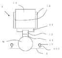
また、図2に示すように、ワーク送り機構5は、ワークWを保持しつつ押し下げるためのワーク保持部11、LMガイド12、ワーク送り本体部13を備えている。ワークWは当て板14に接着されており、また、この当て板14はワークプレート15により保持されている。そして、これらの当て板14、ワークプレート15を介して、ワーク保持部11によりワークWが保持される。このようにして保持されたワークWを、コンピュータ制御でLMガイド12に沿ってワーク保持部11を駆動させることにより、予めプログラムされた送り速度で送り出すことが可能となっている。
このようにワーク送り機構5のワーク保持部11によって保持されたワークWは、切断を行う際、ワーク送り機構5より下方に位置し、軸方向に往復走行するワイヤ2へと送り出されてワイヤ列に押し当てられ、ワイヤ2が当て板14に到達するまで下方に切り込み送りされる。
また、ワイヤ2の上方にはノズル17が配置されており、ワークWの切断を行うときには、スラリ供給機構6からノズル17を通じて、ワークWとワイヤ2との接触部にスラリを供給することができるようになっている。このスラリ供給機構6は、スラリタンク18から、スラリチラー16を介してノズル17に接続されており、供給されるスラリはスラリチラー16により供給温度が制御されてノズル17から供給できるようになっている。
このように構成された図1に示すワイヤソーを用いた場合の、本発明のワークの切断方法について以下説明する。
まず、図2に示すように、切断するワークWをワーク送り機構5により保持する。また、ワイヤ2に張力を付与して軸方向へ往復走行させる。
まず、図2に示すように、切断するワークWをワーク送り機構5により保持する。また、ワイヤ2に張力を付与して軸方向へ往復走行させる。
そして、ワークWの切断を開始する前にワークWを加温する。ここで、ワークWの加温は切断開始前に行っていれば良く、ワークWの保持、ワイヤ2の走行などとの順番に限定されることはなく、例えば、ワークWを加温してからワークWを保持するようにしても良い。また、ワークWを加温する方法は特に限定されず、例えば、恒温槽、ホットプレート、温風式加熱器、ランプ式加熱器などを用いて加温することができる。
この際、切断開始前にワークWを加温する温度は、供給するスラリの切断開始時の温度以上、ワークWの切断中に達するワークWの最高温度以下にする。ワークWの最高温度は、例えば、事前に実験などによって、予め求めておくことができる。
このように、切断開始前に加温するワークWの温度を、供給するスラリの切断開始時の温度以上にすれば、ワークとスラリの接触によるワークの温度が急激に上昇するのを抑制できる。また、この温度をワークWの切断中に達するワークWの最高温度以下とすれば、ワークとスラリの接触によるワークの温度が急激に低下するのを抑制できるし、加温のための時間の増加や、加温するための電力等にかかる経済性や作業性が悪化することもない。
このように、切断開始前に加温するワークWの温度を、供給するスラリの切断開始時の温度以上にすれば、ワークとスラリの接触によるワークの温度が急激に上昇するのを抑制できる。また、この温度をワークWの切断中に達するワークWの最高温度以下とすれば、ワークとスラリの接触によるワークの温度が急激に低下するのを抑制できるし、加温のための時間の増加や、加温するための電力等にかかる経済性や作業性が悪化することもない。
また、ワークWの温度は、例えば、図3に示すように、ワークWの長手方向の両端面に熱電対を設けて測定することができる。そして、これら両熱電対で測定した温度の平均値をワークWの温度とすることができる。
次に、ワーク送り機構5によって保持したワークWを相対的に下降させて、複数のワイヤガイド3間に螺旋状にワイヤ2を巻回することによって形成されるワイヤ列にワークWを押圧する。また、スラリ供給機構6によってワークWとワイヤ2との接触部にスラリを供給する。この供給するスラリの温度はスラリチラー16により所望の温度に制御することができ、例えば、15℃~30℃とすることができるが、特にこれに限定されない。
またここで、使用するスラリの種類は特に限定されず、従来と同様のものを用いることができ、例えばGC(炭化珪素)砥粒を液体に分散させたものを用いることができる。
またここで、使用するスラリの種類は特に限定されず、従来と同様のものを用いることができ、例えばGC(炭化珪素)砥粒を液体に分散させたものを用いることができる。
このようにワイヤ2を走行させながらワークWとワイヤ2との接触部にスラリを供給した状態で、ワークWをワイヤ列に対して切り込み送りさせてワークWをウェーハ状に切断していく。そして、ワイヤ2が当て板14に到達するまでワークWを切り込み送りさせ、ワークWの切断を完了させる。その後、ワークWの送り出し方向を逆転させることにより、ワイヤ列から切断済みワークWを引き抜くようにすることができる。
ここで、ワイヤ2に付与する張力の大きさや、ワイヤ2の走行速度等は適宜設定することができる。例えば、ワイヤの走行速度を、400~800m/minとすることができる。また、ワーク切断時のワイヤ2を往復走行させる際のワイヤ反転サイクルを、例えば60s程度とすることができる。しかし、これらの条件は、これに限定されるわけではない。
このように、切断開始前にワークWを、供給するスラリの切断開始時の温度とワークWの切断中に達するワークWの最高温度の範囲内の温度に加温してから該ワークWを切断すれば、スラリとワークの接触の際に両者の温度差によってワークの温度が急激に変化するのを抑制することができるし、切断中に達するワークWの最高温度は切断開始時のワークWの温度に依存しないので、切断開始から切断終了までのワークWの温度の高低差を縮小させることができ、ワークWの膨張収縮量を抑制可能となる。その結果、ワークWの膨張収縮により発生していたワイヤ列とワークWとの相対位置の変化が抑制され、Warpの発生を抑制することができる。また、このような方法であれば、複雑なワークの温度制御も、そのための追加の装置も必要とせず、従来の装置をそのまま使用して簡単に実施することができるし、製造コストの増加も抑制することができる。
ここで、図2に示すようなワーク送り機構5の例では、ワークWを下方へと押し下げて切り込み送りを行っているが、本発明において、ワークの送り出しは相対的に押し下げることにより行われれば良い。すなわち、ワークWを下方に送るのではなく、ワイヤ列を上方へと押し上げることによって、ワークWの送り出しを行うような構成となっていても良い。
このとき、ワークの切断中に供給するスラリの温度を一定とすることができる。
上記したように、本願の発明者等によって、切断中のワークの最高温度は、切断開始時のワークの温度に依存せず、さらに、ワークの切断中に供給するスラリの温度が一定であれば、このスラリの温度に切断時の摩擦熱を加えた温度でほぼ一定となることが発見されており、スラリの温度を一定とすることで、ワークの切断中に達するワークの最高温度を容易に求めることができる。そして、この求めた最高温度に応じて切断開始前に加温するワークWの温度を容易に設定することができ、切断中に複雑なスラリの温度制御を行うこともなく、Warpを簡単に抑制することができる切断方法となる。
上記したように、本願の発明者等によって、切断中のワークの最高温度は、切断開始時のワークの温度に依存せず、さらに、ワークの切断中に供給するスラリの温度が一定であれば、このスラリの温度に切断時の摩擦熱を加えた温度でほぼ一定となることが発見されており、スラリの温度を一定とすることで、ワークの切断中に達するワークの最高温度を容易に求めることができる。そして、この求めた最高温度に応じて切断開始前に加温するワークWの温度を容易に設定することができ、切断中に複雑なスラリの温度制御を行うこともなく、Warpを簡単に抑制することができる切断方法となる。
但し、本願のワークの切断方法は、切断中のスラリの温度を変更するように制御することを排除するものではない。すなわち、切断開始前に加温することに加えて、切断中のスラリの温度を変更するように制御することによって、より精度良く切断中のワークWの温度の高低差を縮小させるようにすることもできる。
以下、本発明の実施例及び比較例を示して本発明をより具体的に説明するが、本発明はこれらに限定されるものではない。
(実施例1)
図1に示すようなワイヤソーを用い、表1に示すような切断条件で、直径300mm、長さ200mmの円柱状のシリコンインゴットをウェーハ状に切断した。ここで、切断開始前に加温するワークWの温度を24.2℃とし、スラリの温度を24℃で切断中に一定となるように制御した。そして、切断開始前から切断完了までのワークの温度を測定し、切断したウェーハのWarpについて評価した。ワークの温度は、図3に示すように、ワークの両端面に設けた熱電対で測定し、それら測定した温度の平均値を採用した。
図1に示すようなワイヤソーを用い、表1に示すような切断条件で、直径300mm、長さ200mmの円柱状のシリコンインゴットをウェーハ状に切断した。ここで、切断開始前に加温するワークWの温度を24.2℃とし、スラリの温度を24℃で切断中に一定となるように制御した。そして、切断開始前から切断完了までのワークの温度を測定し、切断したウェーハのWarpについて評価した。ワークの温度は、図3に示すように、ワークの両端面に設けた熱電対で測定し、それら測定した温度の平均値を採用した。
測定した温度の結果を図4に示す。図4に示すように、切断中のワークの最高温度は38.6℃であり、後述する比較例1、2と比べ、切断開始から切断終了までのワークの温度の高低差が縮小されていることが分かった。また、切断後のウェーハ全体のWarpの平均値は5.9μmであり、後述する比較例1より17%改善していた。
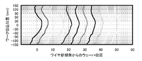
また、ワークの送り方向断面のWarp形状を示したものを図5に示す。前記のようにワークの温度起因によるWarpはワークの両端に顕著に現れるため、図5においてはワークの片端の一部を抜き出し、具体的には、Warp測定データからワイヤの新線供給側の1枚目のウェーハから5枚おきに11枚のウェーハのデータを抜き出したものを示している。図5に示すように、後述する比較例1、2の結果と比較し、ワークの端部近傍の湾曲が抑えられ、良好なWarp形状が得られていることが分かる。
このように、本願のワークの切断方法は、切断開始から切断終了までのワークの温度の高低差を縮小させてワークの膨張収縮量を抑制することができ、Warpの発生を簡単に効果的に抑制することができることを確認できた。
このように、本願のワークの切断方法は、切断開始から切断終了までのワークの温度の高低差を縮小させてワークの膨張収縮量を抑制することができ、Warpの発生を簡単に効果的に抑制することができることを確認できた。
(実施例2)
切断開始前に加温するワークWの温度を28℃とした以外、実施例1と同様な条件でシリコンインゴットをウェーハ状に切断し、実施例1と同様に評価した。
測定した温度の結果を図4に示す。図4に示すように、切断中のワークの最高温度は38.9℃であり、後述する比較例1、2及び実施例1と比べ、切断開始から切断終了までのワークの温度の高低差が縮小されていることが分かった。また、切断後のウェーハ全体のWarpの平均値は5.2μmと実施例1よりもさらに良好な値を得ることができ、後述する比較例1より27%改善していた。
切断開始前に加温するワークWの温度を28℃とした以外、実施例1と同様な条件でシリコンインゴットをウェーハ状に切断し、実施例1と同様に評価した。
測定した温度の結果を図4に示す。図4に示すように、切断中のワークの最高温度は38.9℃であり、後述する比較例1、2及び実施例1と比べ、切断開始から切断終了までのワークの温度の高低差が縮小されていることが分かった。また、切断後のウェーハ全体のWarpの平均値は5.2μmと実施例1よりもさらに良好な値を得ることができ、後述する比較例1より27%改善していた。
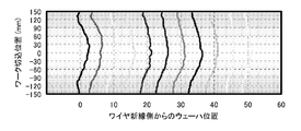
また、実施例1と同様にしてWarp形状を示したものを図6に示す。図6に示すように、実施例1の結果と比較してワークの端部近傍の湾曲がさらに抑えられ、良好なWarp形状が得られていることが分かる。
(比較例1)
切断開始前にワークWを加温せずに切断を開始した以外実施例1と同様な条件でシリコンインゴットを切断し、実施例1と同様に評価した。
測定した温度の結果を図4に示す。図4に示すように、切断開始前のワークWは20.4℃であり、切断中のワークの最高温度は実施例1とほぼ同様の39.2℃であり、切断開始から切断終了までのワークの温度の高低差が実施例1、実施例2と比べ大きくなっていることが分かった。また、切断後のウェーハ全体のWarpの平均値は7.1μmと実施例1、実施例2と比べ悪化していることが分かった。
切断開始前にワークWを加温せずに切断を開始した以外実施例1と同様な条件でシリコンインゴットを切断し、実施例1と同様に評価した。
測定した温度の結果を図4に示す。図4に示すように、切断開始前のワークWは20.4℃であり、切断中のワークの最高温度は実施例1とほぼ同様の39.2℃であり、切断開始から切断終了までのワークの温度の高低差が実施例1、実施例2と比べ大きくなっていることが分かった。また、切断後のウェーハ全体のWarpの平均値は7.1μmと実施例1、実施例2と比べ悪化していることが分かった。
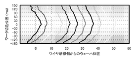
また、実施例1と同様にしてWarp形状を示したものを図7に示す。図7に示すように、ワークの端部近傍が強く湾曲し、Warpの悪化を引き起こしていることが分かる。
(比較例2)
切断開始前にワークWを予想される切断中のワークの最高温度よりも高い温度、39.7℃に加温して切断を開始した以外実施例1と同様な条件でシリコンインゴットを切断し、実施例1と同様に評価した。このとき、切断中のワークの最高温度は実施例1とほぼ同様の39.2℃であった。尚、予想される切断中のワークの最高温度は事前に実験によって求めておいた。
測定した温度の結果を図4に示す。図4に示すように、切断開始後、ワークWの温度はスラリとの接触により急激に低下し、切り込み位置50mm付近でワーク温度が急激に反転していることが分かる。また、切断後のウェーハ全体のWarpの平均値は9.6μmと実施例1、実施例2と比べ大幅に悪化していることが分かった。
切断開始前にワークWを予想される切断中のワークの最高温度よりも高い温度、39.7℃に加温して切断を開始した以外実施例1と同様な条件でシリコンインゴットを切断し、実施例1と同様に評価した。このとき、切断中のワークの最高温度は実施例1とほぼ同様の39.2℃であった。尚、予想される切断中のワークの最高温度は事前に実験によって求めておいた。
測定した温度の結果を図4に示す。図4に示すように、切断開始後、ワークWの温度はスラリとの接触により急激に低下し、切り込み位置50mm付近でワーク温度が急激に反転していることが分かる。また、切断後のウェーハ全体のWarpの平均値は9.6μmと実施例1、実施例2と比べ大幅に悪化していることが分かった。
また、実施例1と同様にしてWarp形状を示したものを図8に示す。図8に示すように、図4に示すようなワーク温度の急激な低下による影響がウェーハの切断面形状に現われており、Warpの悪化を引き起こしていることが分かる。
このように、Warpを改善するためには、切断開始前にワークWを加熱する温度を、供給するスラリの切断開始時の温度以上、ワークの切断中に達するワークの最高温度以下にする必要がある。
このように、Warpを改善するためには、切断開始前にワークWを加熱する温度を、供給するスラリの切断開始時の温度以上、ワークの切断中に達するワークの最高温度以下にする必要がある。

なお、本発明は、上記実施形態に限定されるものではない。上記実施形態は例示であり、本発明の特許請求の範囲に記載された技術的思想と実質的に同一な構成を有し、同様な作用効果を奏するものは、いかなるものであっても本発明の技術的範囲に包含される。
Claims (2)
- 複数のワイヤガイド間に螺旋状にワイヤを巻回することによって形成されるワイヤ列に円柱状のワークを押圧し、前記ワークとワイヤとの接触部にスラリを供給しながら前記ワイヤを走行させることによって、前記ワークをウェーハ状に切断するワークの切断方法において、
切断開始前に前記ワークを、前記供給するスラリの切断開始時の温度以上、前記ワークの切断中に達するワークの最高温度以下の温度に加温してから該ワークを切断することを特徴とするワークの切断方法。
- 前記ワークの切断中に供給するスラリの温度を一定とすることを特徴とする請求項1に記載のワークの切断方法。
Applications Claiming Priority (2)
| Application Number | Priority Date | Filing Date | Title |
|---|---|---|---|
| JP2009139562A JP5201086B2 (ja) | 2009-06-10 | 2009-06-10 | ワークの切断方法 |
| JP2009-139562 | 2009-06-10 |
Publications (1)
| Publication Number | Publication Date |
|---|---|
| WO2010143354A1 true WO2010143354A1 (ja) | 2010-12-16 |
Family
ID=43308617
Family Applications (1)
| Application Number | Title | Priority Date | Filing Date |
|---|---|---|---|
| PCT/JP2010/003108 Ceased WO2010143354A1 (ja) | 2009-06-10 | 2010-05-06 | ワークの切断方法 |
Country Status (3)
| Country | Link |
|---|---|
| JP (1) | JP5201086B2 (ja) |
| TW (1) | TW201105475A (ja) |
| WO (1) | WO2010143354A1 (ja) |
Cited By (2)
| Publication number | Priority date | Publication date | Assignee | Title |
|---|---|---|---|---|
| JP2010284743A (ja) * | 2009-06-10 | 2010-12-24 | Shin Etsu Handotai Co Ltd | ワークの切断方法 |
| CN114872212A (zh) * | 2022-04-22 | 2022-08-09 | 浙江晶盛机电股份有限公司 | 一种砂浆温度控制方法、系统和切片机 |
Families Citing this family (7)
| Publication number | Priority date | Publication date | Assignee | Title |
|---|---|---|---|---|
| JP5590001B2 (ja) | 2011-10-04 | 2014-09-17 | 信越半導体株式会社 | ワークの切断方法及びワイヤソー |
| JP6183074B2 (ja) * | 2013-09-03 | 2017-08-23 | 新日鐵住金株式会社 | 反りの低減が可能なマルチワイヤー加工方法及びマルチワイヤー加工装置 |
| JP6489853B2 (ja) * | 2015-02-03 | 2019-03-27 | 昭和電工株式会社 | マルチワイヤー加工方法及びマルチワイヤー加工装置 |
| TWI577770B (zh) * | 2015-12-10 | 2017-04-11 | Nanya Plastics Corp | An ultraviolet hardening type transparent adhesive |
| WO2018012313A1 (ja) * | 2016-07-13 | 2018-01-18 | 信越半導体株式会社 | ワイヤソー装置及びワークの切断方法 |
| CN108044819B (zh) * | 2017-12-07 | 2020-04-03 | 苏州阿特斯阳光电力科技有限公司 | 一种硅棒切割方法 |
| CN111952063B (zh) * | 2020-06-29 | 2022-01-04 | 扬州宝宣机械有限公司 | 锰环加工工艺 |
Citations (3)
| Publication number | Priority date | Publication date | Assignee | Title |
|---|---|---|---|---|
| WO2005039824A1 (ja) * | 2003-10-27 | 2005-05-06 | Mitsubishi Denki Kabushiki Kaisha | マルチワイヤソー |
| JP2006192555A (ja) * | 2005-01-17 | 2006-07-27 | Toshiba Ceramics Co Ltd | ワイヤソー用研削液、及び、インゴットの切断方法 |
| JP2008078473A (ja) * | 2006-09-22 | 2008-04-03 | Shin Etsu Handotai Co Ltd | 切断方法 |
Family Cites Families (1)
| Publication number | Priority date | Publication date | Assignee | Title |
|---|---|---|---|---|
| JP5201086B2 (ja) * | 2009-06-10 | 2013-06-05 | 信越半導体株式会社 | ワークの切断方法 |
-
2009
- 2009-06-10 JP JP2009139562A patent/JP5201086B2/ja active Active
-
2010
- 2010-05-06 WO PCT/JP2010/003108 patent/WO2010143354A1/ja not_active Ceased
- 2010-05-13 TW TW99115314A patent/TW201105475A/zh unknown
Patent Citations (3)
| Publication number | Priority date | Publication date | Assignee | Title |
|---|---|---|---|---|
| WO2005039824A1 (ja) * | 2003-10-27 | 2005-05-06 | Mitsubishi Denki Kabushiki Kaisha | マルチワイヤソー |
| JP2006192555A (ja) * | 2005-01-17 | 2006-07-27 | Toshiba Ceramics Co Ltd | ワイヤソー用研削液、及び、インゴットの切断方法 |
| JP2008078473A (ja) * | 2006-09-22 | 2008-04-03 | Shin Etsu Handotai Co Ltd | 切断方法 |
Cited By (3)
| Publication number | Priority date | Publication date | Assignee | Title |
|---|---|---|---|---|
| JP2010284743A (ja) * | 2009-06-10 | 2010-12-24 | Shin Etsu Handotai Co Ltd | ワークの切断方法 |
| CN114872212A (zh) * | 2022-04-22 | 2022-08-09 | 浙江晶盛机电股份有限公司 | 一种砂浆温度控制方法、系统和切片机 |
| CN114872212B (zh) * | 2022-04-22 | 2024-05-07 | 浙江晶盛机电股份有限公司 | 一种砂浆温度控制方法、系统和切片机 |
Also Published As
| Publication number | Publication date |
|---|---|
| TW201105475A (en) | 2011-02-16 |
| JP2010284743A (ja) | 2010-12-24 |
| JP5201086B2 (ja) | 2013-06-05 |
Similar Documents
| Publication | Publication Date | Title |
|---|---|---|
| JP5201086B2 (ja) | ワークの切断方法 | |
| JP5056859B2 (ja) | ワイヤソーによるワークの切断方法およびワイヤソー | |
| JP5007706B2 (ja) | ワークの切断方法 | |
| JP4816511B2 (ja) | 切断方法およびワイヤソー装置 | |
| US8167681B2 (en) | Slicing method | |
| CN101517710B (zh) | 切断方法以及外延晶片的制造方法 | |
| US9776340B2 (en) | Method for slicing ingot and wire saw | |
| JP6402700B2 (ja) | ワークの切断方法及びワイヤソー | |
| JP5590001B2 (ja) | ワークの切断方法及びワイヤソー | |
| JP7020286B2 (ja) | インゴットの切断方法及びワイヤーソー | |
| WO2008035513A1 (fr) | procédé de découpe | |
| WO2012144136A1 (ja) | ワイヤソーの運転再開方法及びワイヤソー | |
| KR20160122795A (ko) | 실리콘 웨이퍼의 제조 방법 및 실리콘 웨이퍼 | |
| CN111511504B (zh) | 工件切断方法及线锯 | |
| WO2015075869A1 (ja) | ワークの切断方法 | |
| JP6693460B2 (ja) | ワークの切断方法 | |
| JP2016135529A (ja) | ワークの切断方法 | |
| JP7020454B2 (ja) | ワークの切断方法及びワイヤソー |
Legal Events
| Date | Code | Title | Description |
|---|---|---|---|
| 121 | Ep: the epo has been informed by wipo that ep was designated in this application |
Ref document number: 10785886 Country of ref document: EP Kind code of ref document: A1 |
|
| NENP | Non-entry into the national phase |
Ref country code: DE |
|
| 122 | Ep: pct application non-entry in european phase |
Ref document number: 10785886 Country of ref document: EP Kind code of ref document: A1 |