WO2010143280A1 - 電動車両および電動車両の制御方法 - Google Patents
電動車両および電動車両の制御方法 Download PDFInfo
- Publication number
- WO2010143280A1 WO2010143280A1 PCT/JP2009/060591 JP2009060591W WO2010143280A1 WO 2010143280 A1 WO2010143280 A1 WO 2010143280A1 JP 2009060591 W JP2009060591 W JP 2009060591W WO 2010143280 A1 WO2010143280 A1 WO 2010143280A1
- Authority
- WO
- WIPO (PCT)
- Prior art keywords
- power storage
- storage device
- sub power
- voltage
- selected sub
- Prior art date
- Legal status (The legal status is an assumption and is not a legal conclusion. Google has not performed a legal analysis and makes no representation as to the accuracy of the status listed.)
- Ceased
Links
Images








Classifications
-
- B—PERFORMING OPERATIONS; TRANSPORTING
- B60—VEHICLES IN GENERAL
- B60L—PROPULSION OF ELECTRICALLY-PROPELLED VEHICLES; SUPPLYING ELECTRIC POWER FOR AUXILIARY EQUIPMENT OF ELECTRICALLY-PROPELLED VEHICLES; ELECTRODYNAMIC BRAKE SYSTEMS FOR VEHICLES IN GENERAL; MAGNETIC SUSPENSION OR LEVITATION FOR VEHICLES; MONITORING OPERATING VARIABLES OF ELECTRICALLY-PROPELLED VEHICLES; ELECTRIC SAFETY DEVICES FOR ELECTRICALLY-PROPELLED VEHICLES
- B60L3/00—Electric devices on electrically-propelled vehicles for safety purposes; Monitoring operating variables, e.g. speed, deceleration or energy consumption
- B60L3/0023—Detecting, eliminating, remedying or compensating for drive train abnormalities, e.g. failures within the drive train
- B60L3/0046—Detecting, eliminating, remedying or compensating for drive train abnormalities, e.g. failures within the drive train relating to electric energy storage systems, e.g. batteries or capacitors
-
- B—PERFORMING OPERATIONS; TRANSPORTING
- B60—VEHICLES IN GENERAL
- B60K—ARRANGEMENT OR MOUNTING OF PROPULSION UNITS OR OF TRANSMISSIONS IN VEHICLES; ARRANGEMENT OR MOUNTING OF PLURAL DIVERSE PRIME-MOVERS IN VEHICLES; AUXILIARY DRIVES FOR VEHICLES; INSTRUMENTATION OR DASHBOARDS FOR VEHICLES; ARRANGEMENTS IN CONNECTION WITH COOLING, AIR INTAKE, GAS EXHAUST OR FUEL SUPPLY OF PROPULSION UNITS IN VEHICLES
- B60K6/00—Arrangement or mounting of plural diverse prime-movers for mutual or common propulsion, e.g. hybrid propulsion systems comprising electric motors and internal combustion engines
- B60K6/20—Arrangement or mounting of plural diverse prime-movers for mutual or common propulsion, e.g. hybrid propulsion systems comprising electric motors and internal combustion engines the prime-movers consisting of electric motors and internal combustion engines, e.g. HEVs
- B60K6/22—Arrangement or mounting of plural diverse prime-movers for mutual or common propulsion, e.g. hybrid propulsion systems comprising electric motors and internal combustion engines the prime-movers consisting of electric motors and internal combustion engines, e.g. HEVs characterised by apparatus, components or means specially adapted for HEVs
- B60K6/36—Arrangement or mounting of plural diverse prime-movers for mutual or common propulsion, e.g. hybrid propulsion systems comprising electric motors and internal combustion engines the prime-movers consisting of electric motors and internal combustion engines, e.g. HEVs characterised by apparatus, components or means specially adapted for HEVs characterised by the transmission gearings
- B60K6/365—Arrangement or mounting of plural diverse prime-movers for mutual or common propulsion, e.g. hybrid propulsion systems comprising electric motors and internal combustion engines the prime-movers consisting of electric motors and internal combustion engines, e.g. HEVs characterised by apparatus, components or means specially adapted for HEVs characterised by the transmission gearings with the gears having orbital motion
-
- B—PERFORMING OPERATIONS; TRANSPORTING
- B60—VEHICLES IN GENERAL
- B60K—ARRANGEMENT OR MOUNTING OF PROPULSION UNITS OR OF TRANSMISSIONS IN VEHICLES; ARRANGEMENT OR MOUNTING OF PLURAL DIVERSE PRIME-MOVERS IN VEHICLES; AUXILIARY DRIVES FOR VEHICLES; INSTRUMENTATION OR DASHBOARDS FOR VEHICLES; ARRANGEMENTS IN CONNECTION WITH COOLING, AIR INTAKE, GAS EXHAUST OR FUEL SUPPLY OF PROPULSION UNITS IN VEHICLES
- B60K6/00—Arrangement or mounting of plural diverse prime-movers for mutual or common propulsion, e.g. hybrid propulsion systems comprising electric motors and internal combustion engines
- B60K6/20—Arrangement or mounting of plural diverse prime-movers for mutual or common propulsion, e.g. hybrid propulsion systems comprising electric motors and internal combustion engines the prime-movers consisting of electric motors and internal combustion engines, e.g. HEVs
- B60K6/42—Arrangement or mounting of plural diverse prime-movers for mutual or common propulsion, e.g. hybrid propulsion systems comprising electric motors and internal combustion engines the prime-movers consisting of electric motors and internal combustion engines, e.g. HEVs characterised by the architecture of the hybrid electric vehicle
- B60K6/44—Series-parallel type
- B60K6/445—Differential gearing distribution type
-
- B—PERFORMING OPERATIONS; TRANSPORTING
- B60—VEHICLES IN GENERAL
- B60L—PROPULSION OF ELECTRICALLY-PROPELLED VEHICLES; SUPPLYING ELECTRIC POWER FOR AUXILIARY EQUIPMENT OF ELECTRICALLY-PROPELLED VEHICLES; ELECTRODYNAMIC BRAKE SYSTEMS FOR VEHICLES IN GENERAL; MAGNETIC SUSPENSION OR LEVITATION FOR VEHICLES; MONITORING OPERATING VARIABLES OF ELECTRICALLY-PROPELLED VEHICLES; ELECTRIC SAFETY DEVICES FOR ELECTRICALLY-PROPELLED VEHICLES
- B60L3/00—Electric devices on electrically-propelled vehicles for safety purposes; Monitoring operating variables, e.g. speed, deceleration or energy consumption
- B60L3/04—Cutting off the power supply under fault conditions
-
- B—PERFORMING OPERATIONS; TRANSPORTING
- B60—VEHICLES IN GENERAL
- B60L—PROPULSION OF ELECTRICALLY-PROPELLED VEHICLES; SUPPLYING ELECTRIC POWER FOR AUXILIARY EQUIPMENT OF ELECTRICALLY-PROPELLED VEHICLES; ELECTRODYNAMIC BRAKE SYSTEMS FOR VEHICLES IN GENERAL; MAGNETIC SUSPENSION OR LEVITATION FOR VEHICLES; MONITORING OPERATING VARIABLES OF ELECTRICALLY-PROPELLED VEHICLES; ELECTRIC SAFETY DEVICES FOR ELECTRICALLY-PROPELLED VEHICLES
- B60L50/00—Electric propulsion with power supplied within the vehicle
- B60L50/10—Electric propulsion with power supplied within the vehicle using propulsion power supplied by engine-driven generators, e.g. generators driven by combustion engines
- B60L50/16—Electric propulsion with power supplied within the vehicle using propulsion power supplied by engine-driven generators, e.g. generators driven by combustion engines with provision for separate direct mechanical propulsion
-
- B—PERFORMING OPERATIONS; TRANSPORTING
- B60—VEHICLES IN GENERAL
- B60L—PROPULSION OF ELECTRICALLY-PROPELLED VEHICLES; SUPPLYING ELECTRIC POWER FOR AUXILIARY EQUIPMENT OF ELECTRICALLY-PROPELLED VEHICLES; ELECTRODYNAMIC BRAKE SYSTEMS FOR VEHICLES IN GENERAL; MAGNETIC SUSPENSION OR LEVITATION FOR VEHICLES; MONITORING OPERATING VARIABLES OF ELECTRICALLY-PROPELLED VEHICLES; ELECTRIC SAFETY DEVICES FOR ELECTRICALLY-PROPELLED VEHICLES
- B60L50/00—Electric propulsion with power supplied within the vehicle
- B60L50/50—Electric propulsion with power supplied within the vehicle using propulsion power supplied by batteries or fuel cells
- B60L50/60—Electric propulsion with power supplied within the vehicle using propulsion power supplied by batteries or fuel cells using power supplied by batteries
- B60L50/61—Electric propulsion with power supplied within the vehicle using propulsion power supplied by batteries or fuel cells using power supplied by batteries by batteries charged by engine-driven generators, e.g. series hybrid electric vehicles
-
- B—PERFORMING OPERATIONS; TRANSPORTING
- B60—VEHICLES IN GENERAL
- B60L—PROPULSION OF ELECTRICALLY-PROPELLED VEHICLES; SUPPLYING ELECTRIC POWER FOR AUXILIARY EQUIPMENT OF ELECTRICALLY-PROPELLED VEHICLES; ELECTRODYNAMIC BRAKE SYSTEMS FOR VEHICLES IN GENERAL; MAGNETIC SUSPENSION OR LEVITATION FOR VEHICLES; MONITORING OPERATING VARIABLES OF ELECTRICALLY-PROPELLED VEHICLES; ELECTRIC SAFETY DEVICES FOR ELECTRICALLY-PROPELLED VEHICLES
- B60L58/00—Methods or circuit arrangements for monitoring or controlling batteries or fuel cells, specially adapted for electric vehicles
- B60L58/10—Methods or circuit arrangements for monitoring or controlling batteries or fuel cells, specially adapted for electric vehicles for monitoring or controlling batteries
- B60L58/12—Methods or circuit arrangements for monitoring or controlling batteries or fuel cells, specially adapted for electric vehicles for monitoring or controlling batteries responding to state of charge [SoC]
- B60L58/14—Preventing excessive discharging
-
- B—PERFORMING OPERATIONS; TRANSPORTING
- B60—VEHICLES IN GENERAL
- B60L—PROPULSION OF ELECTRICALLY-PROPELLED VEHICLES; SUPPLYING ELECTRIC POWER FOR AUXILIARY EQUIPMENT OF ELECTRICALLY-PROPELLED VEHICLES; ELECTRODYNAMIC BRAKE SYSTEMS FOR VEHICLES IN GENERAL; MAGNETIC SUSPENSION OR LEVITATION FOR VEHICLES; MONITORING OPERATING VARIABLES OF ELECTRICALLY-PROPELLED VEHICLES; ELECTRIC SAFETY DEVICES FOR ELECTRICALLY-PROPELLED VEHICLES
- B60L58/00—Methods or circuit arrangements for monitoring or controlling batteries or fuel cells, specially adapted for electric vehicles
- B60L58/10—Methods or circuit arrangements for monitoring or controlling batteries or fuel cells, specially adapted for electric vehicles for monitoring or controlling batteries
- B60L58/12—Methods or circuit arrangements for monitoring or controlling batteries or fuel cells, specially adapted for electric vehicles for monitoring or controlling batteries responding to state of charge [SoC]
- B60L58/15—Preventing overcharging
-
- B—PERFORMING OPERATIONS; TRANSPORTING
- B60—VEHICLES IN GENERAL
- B60L—PROPULSION OF ELECTRICALLY-PROPELLED VEHICLES; SUPPLYING ELECTRIC POWER FOR AUXILIARY EQUIPMENT OF ELECTRICALLY-PROPELLED VEHICLES; ELECTRODYNAMIC BRAKE SYSTEMS FOR VEHICLES IN GENERAL; MAGNETIC SUSPENSION OR LEVITATION FOR VEHICLES; MONITORING OPERATING VARIABLES OF ELECTRICALLY-PROPELLED VEHICLES; ELECTRIC SAFETY DEVICES FOR ELECTRICALLY-PROPELLED VEHICLES
- B60L58/00—Methods or circuit arrangements for monitoring or controlling batteries or fuel cells, specially adapted for electric vehicles
- B60L58/10—Methods or circuit arrangements for monitoring or controlling batteries or fuel cells, specially adapted for electric vehicles for monitoring or controlling batteries
- B60L58/18—Methods or circuit arrangements for monitoring or controlling batteries or fuel cells, specially adapted for electric vehicles for monitoring or controlling batteries of two or more battery modules
-
- B—PERFORMING OPERATIONS; TRANSPORTING
- B60—VEHICLES IN GENERAL
- B60L—PROPULSION OF ELECTRICALLY-PROPELLED VEHICLES; SUPPLYING ELECTRIC POWER FOR AUXILIARY EQUIPMENT OF ELECTRICALLY-PROPELLED VEHICLES; ELECTRODYNAMIC BRAKE SYSTEMS FOR VEHICLES IN GENERAL; MAGNETIC SUSPENSION OR LEVITATION FOR VEHICLES; MONITORING OPERATING VARIABLES OF ELECTRICALLY-PROPELLED VEHICLES; ELECTRIC SAFETY DEVICES FOR ELECTRICALLY-PROPELLED VEHICLES
- B60L58/00—Methods or circuit arrangements for monitoring or controlling batteries or fuel cells, specially adapted for electric vehicles
- B60L58/10—Methods or circuit arrangements for monitoring or controlling batteries or fuel cells, specially adapted for electric vehicles for monitoring or controlling batteries
- B60L58/24—Methods or circuit arrangements for monitoring or controlling batteries or fuel cells, specially adapted for electric vehicles for monitoring or controlling batteries for controlling the temperature of batteries
-
- B—PERFORMING OPERATIONS; TRANSPORTING
- B60—VEHICLES IN GENERAL
- B60L—PROPULSION OF ELECTRICALLY-PROPELLED VEHICLES; SUPPLYING ELECTRIC POWER FOR AUXILIARY EQUIPMENT OF ELECTRICALLY-PROPELLED VEHICLES; ELECTRODYNAMIC BRAKE SYSTEMS FOR VEHICLES IN GENERAL; MAGNETIC SUSPENSION OR LEVITATION FOR VEHICLES; MONITORING OPERATING VARIABLES OF ELECTRICALLY-PROPELLED VEHICLES; ELECTRIC SAFETY DEVICES FOR ELECTRICALLY-PROPELLED VEHICLES
- B60L7/00—Electrodynamic brake systems for vehicles in general
- B60L7/10—Dynamic electric regenerative braking
- B60L7/14—Dynamic electric regenerative braking for vehicles propelled by AC motors
-
- B—PERFORMING OPERATIONS; TRANSPORTING
- B60—VEHICLES IN GENERAL
- B60L—PROPULSION OF ELECTRICALLY-PROPELLED VEHICLES; SUPPLYING ELECTRIC POWER FOR AUXILIARY EQUIPMENT OF ELECTRICALLY-PROPELLED VEHICLES; ELECTRODYNAMIC BRAKE SYSTEMS FOR VEHICLES IN GENERAL; MAGNETIC SUSPENSION OR LEVITATION FOR VEHICLES; MONITORING OPERATING VARIABLES OF ELECTRICALLY-PROPELLED VEHICLES; ELECTRIC SAFETY DEVICES FOR ELECTRICALLY-PROPELLED VEHICLES
- B60L7/00—Electrodynamic brake systems for vehicles in general
- B60L7/10—Dynamic electric regenerative braking
- B60L7/16—Dynamic electric regenerative braking for vehicles comprising converters between the power source and the motor
-
- B—PERFORMING OPERATIONS; TRANSPORTING
- B60—VEHICLES IN GENERAL
- B60W—CONJOINT CONTROL OF VEHICLE SUB-UNITS OF DIFFERENT TYPE OR DIFFERENT FUNCTION; CONTROL SYSTEMS SPECIALLY ADAPTED FOR HYBRID VEHICLES; ROAD VEHICLE DRIVE CONTROL SYSTEMS FOR PURPOSES NOT RELATED TO THE CONTROL OF A PARTICULAR SUB-UNIT
- B60W10/00—Conjoint control of vehicle sub-units of different type or different function
- B60W10/04—Conjoint control of vehicle sub-units of different type or different function including control of propulsion units
- B60W10/08—Conjoint control of vehicle sub-units of different type or different function including control of propulsion units including control of electric propulsion units, e.g. motors or generators
-
- B—PERFORMING OPERATIONS; TRANSPORTING
- B60—VEHICLES IN GENERAL
- B60W—CONJOINT CONTROL OF VEHICLE SUB-UNITS OF DIFFERENT TYPE OR DIFFERENT FUNCTION; CONTROL SYSTEMS SPECIALLY ADAPTED FOR HYBRID VEHICLES; ROAD VEHICLE DRIVE CONTROL SYSTEMS FOR PURPOSES NOT RELATED TO THE CONTROL OF A PARTICULAR SUB-UNIT
- B60W10/00—Conjoint control of vehicle sub-units of different type or different function
- B60W10/24—Conjoint control of vehicle sub-units of different type or different function including control of energy storage means
- B60W10/26—Conjoint control of vehicle sub-units of different type or different function including control of energy storage means for electrical energy, e.g. batteries or capacitors
-
- B—PERFORMING OPERATIONS; TRANSPORTING
- B60—VEHICLES IN GENERAL
- B60W—CONJOINT CONTROL OF VEHICLE SUB-UNITS OF DIFFERENT TYPE OR DIFFERENT FUNCTION; CONTROL SYSTEMS SPECIALLY ADAPTED FOR HYBRID VEHICLES; ROAD VEHICLE DRIVE CONTROL SYSTEMS FOR PURPOSES NOT RELATED TO THE CONTROL OF A PARTICULAR SUB-UNIT
- B60W20/00—Control systems specially adapted for hybrid vehicles
- B60W20/10—Controlling the power contribution of each of the prime movers to meet required power demand
- B60W20/13—Controlling the power contribution of each of the prime movers to meet required power demand in order to stay within battery power input or output limits; in order to prevent overcharging or battery depletion
-
- H—ELECTRICITY
- H01—ELECTRIC ELEMENTS
- H01M—PROCESSES OR MEANS, e.g. BATTERIES, FOR THE DIRECT CONVERSION OF CHEMICAL ENERGY INTO ELECTRICAL ENERGY
- H01M10/00—Secondary cells; Manufacture thereof
- H01M10/42—Methods or arrangements for servicing or maintenance of secondary cells or secondary half-cells
- H01M10/44—Methods for charging or discharging
- H01M10/441—Methods for charging or discharging for several batteries or cells simultaneously or sequentially
-
- H—ELECTRICITY
- H02—GENERATION; CONVERSION OR DISTRIBUTION OF ELECTRIC POWER
- H02J—ELECTRIC POWER NETWORKS; CIRCUIT ARRANGEMENTS OR SYSTEMS FOR SUPPLYING OR DISTRIBUTING ELECTRIC POWER; SYSTEMS FOR STORING ELECTRIC ENERGY
- H02J4/00—Circuit arrangements for mains or distribution networks not specified as AC or DC; Circuit arrangements for mains or distribution networks combining AC and DC sections or sub-networks
- H02J4/20—Networks integrating separated AC and DC power sections
- H02J4/25—Networks integrating separated AC and DC power sections for transfer of electric power between AC and DC networks, e.g. for supplying the DC section within a load from an AC mains system
-
- H—ELECTRICITY
- H02—GENERATION; CONVERSION OR DISTRIBUTION OF ELECTRIC POWER
- H02J—ELECTRIC POWER NETWORKS; CIRCUIT ARRANGEMENTS OR SYSTEMS FOR SUPPLYING OR DISTRIBUTING ELECTRIC POWER; SYSTEMS FOR STORING ELECTRIC ENERGY
- H02J7/00—Circuit arrangements for charging or discharging batteries or for supplying loads from batteries
- H02J7/02—Circuit arrangements for charging or discharging batteries or for supplying loads from batteries for charging batteries from AC mains by converters
-
- B—PERFORMING OPERATIONS; TRANSPORTING
- B60—VEHICLES IN GENERAL
- B60K—ARRANGEMENT OR MOUNTING OF PROPULSION UNITS OR OF TRANSMISSIONS IN VEHICLES; ARRANGEMENT OR MOUNTING OF PLURAL DIVERSE PRIME-MOVERS IN VEHICLES; AUXILIARY DRIVES FOR VEHICLES; INSTRUMENTATION OR DASHBOARDS FOR VEHICLES; ARRANGEMENTS IN CONNECTION WITH COOLING, AIR INTAKE, GAS EXHAUST OR FUEL SUPPLY OF PROPULSION UNITS IN VEHICLES
- B60K1/00—Arrangement or mounting of electrical propulsion units
- B60K1/02—Arrangement or mounting of electrical propulsion units comprising more than one electric motor
-
- B—PERFORMING OPERATIONS; TRANSPORTING
- B60—VEHICLES IN GENERAL
- B60L—PROPULSION OF ELECTRICALLY-PROPELLED VEHICLES; SUPPLYING ELECTRIC POWER FOR AUXILIARY EQUIPMENT OF ELECTRICALLY-PROPELLED VEHICLES; ELECTRODYNAMIC BRAKE SYSTEMS FOR VEHICLES IN GENERAL; MAGNETIC SUSPENSION OR LEVITATION FOR VEHICLES; MONITORING OPERATING VARIABLES OF ELECTRICALLY-PROPELLED VEHICLES; ELECTRIC SAFETY DEVICES FOR ELECTRICALLY-PROPELLED VEHICLES
- B60L2210/00—Converter types
- B60L2210/10—DC to DC converters
- B60L2210/14—Boost converters
-
- B—PERFORMING OPERATIONS; TRANSPORTING
- B60—VEHICLES IN GENERAL
- B60L—PROPULSION OF ELECTRICALLY-PROPELLED VEHICLES; SUPPLYING ELECTRIC POWER FOR AUXILIARY EQUIPMENT OF ELECTRICALLY-PROPELLED VEHICLES; ELECTRODYNAMIC BRAKE SYSTEMS FOR VEHICLES IN GENERAL; MAGNETIC SUSPENSION OR LEVITATION FOR VEHICLES; MONITORING OPERATING VARIABLES OF ELECTRICALLY-PROPELLED VEHICLES; ELECTRIC SAFETY DEVICES FOR ELECTRICALLY-PROPELLED VEHICLES
- B60L2220/00—Electrical machine types; Structures or applications thereof
- B60L2220/10—Electrical machine types
- B60L2220/14—Synchronous machines
-
- B—PERFORMING OPERATIONS; TRANSPORTING
- B60—VEHICLES IN GENERAL
- B60L—PROPULSION OF ELECTRICALLY-PROPELLED VEHICLES; SUPPLYING ELECTRIC POWER FOR AUXILIARY EQUIPMENT OF ELECTRICALLY-PROPELLED VEHICLES; ELECTRODYNAMIC BRAKE SYSTEMS FOR VEHICLES IN GENERAL; MAGNETIC SUSPENSION OR LEVITATION FOR VEHICLES; MONITORING OPERATING VARIABLES OF ELECTRICALLY-PROPELLED VEHICLES; ELECTRIC SAFETY DEVICES FOR ELECTRICALLY-PROPELLED VEHICLES
- B60L2240/00—Control parameters of input or output; Target parameters
- B60L2240/40—Drive Train control parameters
- B60L2240/42—Drive Train control parameters related to electric machines
- B60L2240/423—Torque
-
- B—PERFORMING OPERATIONS; TRANSPORTING
- B60—VEHICLES IN GENERAL
- B60L—PROPULSION OF ELECTRICALLY-PROPELLED VEHICLES; SUPPLYING ELECTRIC POWER FOR AUXILIARY EQUIPMENT OF ELECTRICALLY-PROPELLED VEHICLES; ELECTRODYNAMIC BRAKE SYSTEMS FOR VEHICLES IN GENERAL; MAGNETIC SUSPENSION OR LEVITATION FOR VEHICLES; MONITORING OPERATING VARIABLES OF ELECTRICALLY-PROPELLED VEHICLES; ELECTRIC SAFETY DEVICES FOR ELECTRICALLY-PROPELLED VEHICLES
- B60L2250/00—Driver interactions
- B60L2250/26—Driver interactions by pedal actuation
-
- B—PERFORMING OPERATIONS; TRANSPORTING
- B60—VEHICLES IN GENERAL
- B60W—CONJOINT CONTROL OF VEHICLE SUB-UNITS OF DIFFERENT TYPE OR DIFFERENT FUNCTION; CONTROL SYSTEMS SPECIALLY ADAPTED FOR HYBRID VEHICLES; ROAD VEHICLE DRIVE CONTROL SYSTEMS FOR PURPOSES NOT RELATED TO THE CONTROL OF A PARTICULAR SUB-UNIT
- B60W20/00—Control systems specially adapted for hybrid vehicles
-
- B—PERFORMING OPERATIONS; TRANSPORTING
- B60—VEHICLES IN GENERAL
- B60W—CONJOINT CONTROL OF VEHICLE SUB-UNITS OF DIFFERENT TYPE OR DIFFERENT FUNCTION; CONTROL SYSTEMS SPECIALLY ADAPTED FOR HYBRID VEHICLES; ROAD VEHICLE DRIVE CONTROL SYSTEMS FOR PURPOSES NOT RELATED TO THE CONTROL OF A PARTICULAR SUB-UNIT
- B60W2510/00—Input parameters relating to a particular sub-units
- B60W2510/24—Energy storage means
- B60W2510/242—Energy storage means for electrical energy
- B60W2510/244—Charge state
-
- B—PERFORMING OPERATIONS; TRANSPORTING
- B60—VEHICLES IN GENERAL
- B60W—CONJOINT CONTROL OF VEHICLE SUB-UNITS OF DIFFERENT TYPE OR DIFFERENT FUNCTION; CONTROL SYSTEMS SPECIALLY ADAPTED FOR HYBRID VEHICLES; ROAD VEHICLE DRIVE CONTROL SYSTEMS FOR PURPOSES NOT RELATED TO THE CONTROL OF A PARTICULAR SUB-UNIT
- B60W2510/00—Input parameters relating to a particular sub-units
- B60W2510/24—Energy storage means
- B60W2510/242—Energy storage means for electrical energy
- B60W2510/246—Temperature
-
- B—PERFORMING OPERATIONS; TRANSPORTING
- B60—VEHICLES IN GENERAL
- B60W—CONJOINT CONTROL OF VEHICLE SUB-UNITS OF DIFFERENT TYPE OR DIFFERENT FUNCTION; CONTROL SYSTEMS SPECIALLY ADAPTED FOR HYBRID VEHICLES; ROAD VEHICLE DRIVE CONTROL SYSTEMS FOR PURPOSES NOT RELATED TO THE CONTROL OF A PARTICULAR SUB-UNIT
- B60W2540/00—Input parameters relating to occupants
- B60W2540/12—Brake pedal position
-
- H—ELECTRICITY
- H01—ELECTRIC ELEMENTS
- H01M—PROCESSES OR MEANS, e.g. BATTERIES, FOR THE DIRECT CONVERSION OF CHEMICAL ENERGY INTO ELECTRICAL ENERGY
- H01M10/00—Secondary cells; Manufacture thereof
- H01M10/42—Methods or arrangements for servicing or maintenance of secondary cells or secondary half-cells
- H01M10/44—Methods for charging or discharging
-
- Y—GENERAL TAGGING OF NEW TECHNOLOGICAL DEVELOPMENTS; GENERAL TAGGING OF CROSS-SECTIONAL TECHNOLOGIES SPANNING OVER SEVERAL SECTIONS OF THE IPC; TECHNICAL SUBJECTS COVERED BY FORMER USPC CROSS-REFERENCE ART COLLECTIONS [XRACs] AND DIGESTS
- Y02—TECHNOLOGIES OR APPLICATIONS FOR MITIGATION OR ADAPTATION AGAINST CLIMATE CHANGE
- Y02E—REDUCTION OF GREENHOUSE GAS [GHG] EMISSIONS, RELATED TO ENERGY GENERATION, TRANSMISSION OR DISTRIBUTION
- Y02E60/00—Enabling technologies; Technologies with a potential or indirect contribution to GHG emissions mitigation
- Y02E60/10—Energy storage using batteries
-
- Y—GENERAL TAGGING OF NEW TECHNOLOGICAL DEVELOPMENTS; GENERAL TAGGING OF CROSS-SECTIONAL TECHNOLOGIES SPANNING OVER SEVERAL SECTIONS OF THE IPC; TECHNICAL SUBJECTS COVERED BY FORMER USPC CROSS-REFERENCE ART COLLECTIONS [XRACs] AND DIGESTS
- Y02—TECHNOLOGIES OR APPLICATIONS FOR MITIGATION OR ADAPTATION AGAINST CLIMATE CHANGE
- Y02T—CLIMATE CHANGE MITIGATION TECHNOLOGIES RELATED TO TRANSPORTATION
- Y02T10/00—Road transport of goods or passengers
- Y02T10/60—Other road transportation technologies with climate change mitigation effect
- Y02T10/62—Hybrid vehicles
-
- Y—GENERAL TAGGING OF NEW TECHNOLOGICAL DEVELOPMENTS; GENERAL TAGGING OF CROSS-SECTIONAL TECHNOLOGIES SPANNING OVER SEVERAL SECTIONS OF THE IPC; TECHNICAL SUBJECTS COVERED BY FORMER USPC CROSS-REFERENCE ART COLLECTIONS [XRACs] AND DIGESTS
- Y02—TECHNOLOGIES OR APPLICATIONS FOR MITIGATION OR ADAPTATION AGAINST CLIMATE CHANGE
- Y02T—CLIMATE CHANGE MITIGATION TECHNOLOGIES RELATED TO TRANSPORTATION
- Y02T10/00—Road transport of goods or passengers
- Y02T10/60—Other road transportation technologies with climate change mitigation effect
- Y02T10/64—Electric machine technologies in electromobility
-
- Y—GENERAL TAGGING OF NEW TECHNOLOGICAL DEVELOPMENTS; GENERAL TAGGING OF CROSS-SECTIONAL TECHNOLOGIES SPANNING OVER SEVERAL SECTIONS OF THE IPC; TECHNICAL SUBJECTS COVERED BY FORMER USPC CROSS-REFERENCE ART COLLECTIONS [XRACs] AND DIGESTS
- Y02—TECHNOLOGIES OR APPLICATIONS FOR MITIGATION OR ADAPTATION AGAINST CLIMATE CHANGE
- Y02T—CLIMATE CHANGE MITIGATION TECHNOLOGIES RELATED TO TRANSPORTATION
- Y02T10/00—Road transport of goods or passengers
- Y02T10/60—Other road transportation technologies with climate change mitigation effect
- Y02T10/70—Energy storage systems for electromobility, e.g. batteries
-
- Y—GENERAL TAGGING OF NEW TECHNOLOGICAL DEVELOPMENTS; GENERAL TAGGING OF CROSS-SECTIONAL TECHNOLOGIES SPANNING OVER SEVERAL SECTIONS OF THE IPC; TECHNICAL SUBJECTS COVERED BY FORMER USPC CROSS-REFERENCE ART COLLECTIONS [XRACs] AND DIGESTS
- Y02—TECHNOLOGIES OR APPLICATIONS FOR MITIGATION OR ADAPTATION AGAINST CLIMATE CHANGE
- Y02T—CLIMATE CHANGE MITIGATION TECHNOLOGIES RELATED TO TRANSPORTATION
- Y02T10/00—Road transport of goods or passengers
- Y02T10/60—Other road transportation technologies with climate change mitigation effect
- Y02T10/7072—Electromobility specific charging systems or methods for batteries, ultracapacitors, supercapacitors or double-layer capacitors
-
- Y—GENERAL TAGGING OF NEW TECHNOLOGICAL DEVELOPMENTS; GENERAL TAGGING OF CROSS-SECTIONAL TECHNOLOGIES SPANNING OVER SEVERAL SECTIONS OF THE IPC; TECHNICAL SUBJECTS COVERED BY FORMER USPC CROSS-REFERENCE ART COLLECTIONS [XRACs] AND DIGESTS
- Y02—TECHNOLOGIES OR APPLICATIONS FOR MITIGATION OR ADAPTATION AGAINST CLIMATE CHANGE
- Y02T—CLIMATE CHANGE MITIGATION TECHNOLOGIES RELATED TO TRANSPORTATION
- Y02T10/00—Road transport of goods or passengers
- Y02T10/60—Other road transportation technologies with climate change mitigation effect
- Y02T10/72—Electric energy management in electromobility
Definitions
- the present invention relates to an electric vehicle and an electric vehicle control method, and more particularly to control of an electric vehicle equipped with a power supply system including a main power storage device and a plurality of sub power storage devices.
- electric vehicles such as electric vehicles, hybrid vehicles, and fuel cell vehicles have been developed and put into practical use as environmentally friendly vehicles.
- These electric vehicles are equipped with an electric motor for generating vehicle driving force and a power supply system for supplying electric motor driving power including an electric storage device.
- Patent Document 1 Japanese Patent Application Laid-Open No. 2008-109840
- Patent Document 2 Japanese Patent Application Laid-Open No. 2003-209969
- Patent Document 3 in Japanese Patent Application Laid-Open No. 2008-167620, in a vehicle equipped with a main power storage device and a plurality of sub power storage devices, a converter corresponding to the main power storage device and a plurality of sub power storage devices are disclosed. Describes a configuration of a power supply device provided with a converter shared by the. According to this configuration, it is possible to increase the amount of energy that can be stored while suppressing the number of elements of the device.
- one of the plurality of sub power storage devices is selectively connected to the converter, and the driving power of the vehicle driving motor is supplied by the main power storage device and the selected sub power storage device. Is done.
- a power supply device when the SOC (State of Charge) of the sub power storage device in use decreases, a plurality of sub power storage devices are sequentially used so as to connect the new sub power storage device and the converter.
- the travel distance EV (Electric Vehicle) travel distance
- the present invention has been made to solve such problems, and an object of the present invention is to provide a sub power storage in an electric vehicle equipped with a power supply system including a main power storage device and a plurality of sub power storage devices. This is to prevent the device separation process from adversely affecting the braking of the electric vehicle.
- the present invention is an electric vehicle.
- the electric vehicle includes a motor, an inverter, a main power storage device, a feed line, a first voltage converter, a plurality of sub power storage devices, a second voltage converter, a connection unit, and a connection control unit.
- the motor can generate vehicle drive power and can perform regenerative braking.
- the inverter controls the motor.
- the power supply line supplies power to the inverter to generate vehicle driving power by the motor, and transmits power output from the inverter by regenerative braking of the motor.
- the first voltage converter is provided between the power supply line and the main power storage device, and is configured to perform bidirectional voltage conversion.
- the plurality of sub power storage devices are provided in parallel with each other.
- the second voltage converter is provided between the plurality of sub power storage devices and the power supply line, and performs bidirectional voltage conversion between the selected sub power storage device and the power supply line among the plurality of sub power storage devices.
- the connection unit is provided between the plurality of sub power storage devices and the second voltage converter, and is configured to connect and disconnect the selected sub power storage device with respect to the second voltage converter.
- the connection control unit sets the selected sub power storage device to the second voltage based on the state of charge of the selected sub power storage device when there is no new sub power storage device exchangeable with the selected sub power storage device. It is configured to perform a separation process for disconnecting from the converter.
- the travel control unit is configured to execute a braking process for controlling the inverter for regenerative braking by the motor.
- the selection control unit is configured to prohibit the execution of the other process during the execution of one of the disconnection process by the connection control unit and the braking process by the travel control unit.
- the separation process includes first to fourth processes.
- the first process is a process of determining whether or not it is necessary to disconnect the selected sub power storage device from the second voltage converter based on the state of charge of the selected sub power storage device.
- the voltage of the power supply line is higher than the output voltage of the main power storage device and the output voltage of the selected sub power storage device.
- the first voltage converter is controlled so that
- the third process is a process of setting the input / output power upper limit value by the selected sub power storage device to zero after the voltage of the power supply line reaches a predetermined voltage.
- the fourth process is a process of controlling the connection unit so that the selected sub power storage device is disconnected from the second voltage converter in response to the input / output power upper limit value being set to zero.
- the connection control unit is configured to execute a disconnection determination unit configured to execute the first process, a boost instruction unit configured to execute the second process, and a third process A power limiting unit configured to perform the fourth process.
- the power limiting unit is configured to gradually decrease the input / output power upper limit value to zero when the third process is executed.
- one process is a braking process.
- the other process is a separation process.
- one process is a separation process.
- the other process is a braking process.
- the electric vehicle further includes a hydraulic brake and a brake control unit.
- the hydraulic brake can generate the braking force of the electric vehicle independently of the regenerative braking by the motor.
- the brake control unit is configured to execute braking using only the hydraulic brake when a braking request for the electric vehicle is generated during the disconnection process.
- the present invention is a method for controlling an electric vehicle.
- the electric vehicle includes a motor, an inverter, a main power storage device, a feed line, a first voltage converter, a plurality of sub power storage devices, a second voltage converter, a connection unit, and a control device.
- the motor can generate vehicle drive power and can perform regenerative braking.
- the inverter controls the motor.
- the power supply line supplies power to the inverter to generate vehicle driving power by the motor, and transmits power output from the inverter by regenerative braking of the motor.
- the first voltage converter is provided between the power supply line and the main power storage device, and is configured to perform bidirectional voltage conversion.
- the plurality of sub power storage devices are provided in parallel with each other.
- the second voltage converter is provided between the plurality of sub power storage devices and the power supply line, and performs bidirectional voltage conversion between the selected sub power storage device and the power supply line among the plurality of sub power storage devices.
- the connection unit is provided between the plurality of sub power storage devices and the second voltage converter, and is configured to connect and disconnect the selected sub power storage device with respect to the second voltage converter.
- the control device is configured to control the inverter and the connection. According to the control method, when there is no new sub power storage device exchangeable with the selected sub power storage device, the selected sub power storage device is subjected to the second voltage conversion based on the state of charge of the selected sub power storage device.
- the separation process includes first to fourth processes.
- the first process is a process of determining whether or not it is necessary to disconnect the selected sub power storage device from the second voltage converter based on the state of charge of the selected sub power storage device.
- the voltage of the power supply line is higher than the output voltage of the main power storage device and the output voltage of the selected sub power storage device.
- the first voltage converter is controlled so that
- the third process is a process of setting the input / output power upper limit value by the selected sub power storage device to zero after the voltage of the power supply line reaches a predetermined voltage.
- the fourth process is a process of controlling the connection unit so that the selected sub power storage device is disconnected from the second voltage converter in response to the input / output power upper limit value being set to zero.
- the step of executing the separation process includes a step of executing the first process, a step of executing the second process, a step of executing the third process, and a step of executing the fourth process. .
- the step of executing the third process includes a step of gradually decreasing the input / output power upper limit value to zero.
- one process is a braking process.
- the other process is a separation process.
- one process is a separation process.
- the other process is a braking process.
- the electric vehicle further includes a hydraulic brake capable of generating a braking force of the electric vehicle independently of the regenerative braking by the motor.
- the control device is configured to control braking by the hydraulic brake.
- the control method further includes a step of executing braking using only the hydraulic brake when a braking request for the electric vehicle is generated during the disconnection process.
- the present invention in an electric vehicle equipped with a power supply system including a main power storage device and a plurality of sub power storage devices, it is possible to prevent the disconnection process of the sub power storage device from adversely affecting braking of the electric vehicle. .
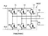
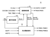
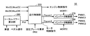
- FIG. 2 is a circuit diagram showing a detailed configuration of each inverter shown in FIG. 1. It is a circuit diagram which shows the detailed structure of each converter shown in FIG. It is a functional block diagram of the control apparatus 30 shown in FIG. It is a functional block diagram of the electric system control part 31 shown in FIG. It is a functional block diagram explaining the structure of the charging / discharging control part 52 shown in FIG. It is a flowchart which shows the rough process sequence of the separation process of the selection sub electrical storage apparatus in the power supply system of the electric vehicle by embodiment of this invention. It is a flowchart explaining the detail of the disconnection determination process of the selection sub electrical storage apparatus shown in FIG.
- FIG. 12 It is a figure for demonstrating the relationship between a user's brake operation amount and the execution amount of regenerative braking. It is a functional block diagram explaining the structure of 30 A of control apparatuses with which the electric vehicle which concerns on Embodiment 2 is provided. It is a functional block diagram explaining the structure of 31 A of electric system control parts shown in FIG. 12 is a flowchart illustrating details of a separation determination process according to the second embodiment. It is a flowchart explaining the process of 53 A of selection control parts shown in FIG. It is a flowchart explaining the process of the brake control part 32A shown in FIG.
- FIG. 1 is a diagram showing a main configuration of an electric vehicle according to Embodiment 1 of the present invention.
- electric vehicle 1 includes batteries BA, BB1, and BB2, which are power storage devices, connection portions 39A and 39B, converters 12A and 12B, smoothing capacitors C1, C2, and CH, and voltage sensor 10A. , 10B1, 10B2, 13, 21A, 21B, temperature sensors 11A, 11B1, 11B2, current sensors 9A, 9B1, 9B2, power supply line PL2, inverters 14, 22, motor generators MG1, MG2, and wheels 2 Power split mechanism 3, engine 4, and control device 30.
- batteries BA, BB1, and BB2 which are power storage devices, connection portions 39A and 39B, converters 12A and 12B, smoothing capacitors C1, C2, and CH, and voltage sensor 10A.
- Power split mechanism 3 engine 4, and control device 30.
- the power supply system for the electric vehicle shown in the present embodiment includes a battery BA that is a main power storage device, a power supply line PL2 that supplies power to inverter 14 that drives motor generator MG2, and a main power storage device (BA) and power supply line PL2.
- Converter 12A that is a voltage converter that is provided between and a voltage converter that performs bidirectional voltage conversion, batteries BB1 and BB2 that are a plurality of sub power storage devices provided in parallel to each other, and a plurality of sub power storage devices (BB1) , BB2) and a power supply line PL2 and a converter 12B that is a voltage converter that performs bidirectional voltage conversion.
- the voltage converter (12B) is selectively connected to any one of the plurality of sub power storage devices (BB1, BB2), and performs bidirectional voltage conversion with the power feed line PL2.
- the sub power storage device (one of BB1 or BB2) and the main power storage device (BA) can output, for example, the maximum power allowed for the electrical load (22, MG2) connected to the power supply line by simultaneous use.
- the chargeable capacity is set as shown.
- EV Electric Vehicle
- running without using the engine can run at maximum power. If the power storage state of the sub power storage device deteriorates, the sub power storage device may be replaced and run further. If the power of the sub power storage device is consumed, the maximum power can be traveled without using the sub power storage device by using the engine in addition to the main power storage device.
- the converter 12B is shared by a plurality of sub power storage devices, so that the number of converters need not be increased by the number of power storage devices.
- a battery may be added in parallel to the batteries BB1 and BB2.
- the main power storage device and the sub power storage device mounted on the electric vehicle can be externally charged.
- electrically powered vehicle 1 further includes a battery charging device (charging converter) 6 for connection to an external power supply 8 which is a commercial power supply of AC 100V, for example.
- the battery charging device (6) converts alternating current into direct current and regulates the voltage to supply charging power for the battery.
- the configuration enabling external charging includes a system in which the neutral point of the stator coils of motor generators MG1 and MG2 is connected to an AC power supply, and converters 12A and 12B combined to form an AC / DC converter. A functioning method may be used.
- Smoothing capacitor C1 is connected between power supply line PL1A and ground line SL2.
- the voltage sensor 21 ⁇ / b> A detects the voltage VLA across the smoothing capacitor C ⁇ b> 1 and outputs it to the control device 30.
- Converter 12A can boost the voltage across terminals of smoothing capacitor C1 and supply the boosted voltage to power supply line PL2.
- Smoothing capacitor C2 is connected between power supply line PL1B and ground line SL2.
- the voltage sensor 21B detects the voltage VLB across the smoothing capacitor C2 and outputs it to the control device 30.
- Converter 12B can boost the voltage across terminals of smoothing capacitor C2 and supply it to power supply line PL2.
- Smoothing capacitor CH smoothes the voltage boosted by converters 12A and 12B.
- the voltage sensor 13 detects the inter-terminal voltage VH of the smoothing capacitor CH and outputs it to the control device 30.
- converters 12A and 12B can step down voltage VH between terminals smoothed by smoothing capacitor CH and supply it to power supply lines PL1A and PL1B.
- the inverter 14 converts the DC voltage supplied from the converter 12B and / or 12A into a three-phase AC voltage and outputs it to the motor generator MG1.
- Inverter 22 converts the DC voltage applied from converters 12B and / or 12A into a three-phase AC voltage and outputs the same to motor generator MG2.
- the power split mechanism 3 is a mechanism that is coupled to the engine 4 and the motor generators MG1 and MG2 and distributes power between them.
- a planetary gear mechanism having three rotating shafts of a sun gear, a planetary carrier, and a ring gear can be used.
- rotation of two of the three rotation shafts is determined, rotation of the other one rotation shaft is forcibly determined.
- the rotating shaft of motor generator MG2 is coupled to wheel 2 by a reduction gear and a differential gear (not shown). Further, a reduction gear for the rotation shaft of motor generator MG2 may be further incorporated in power split device 3.
- Connection portion 39A includes a system main relay SMR2 connected between the positive electrode of battery BA and power supply line PL1A, a system main relay SMR1 connected in series with system main relay SMR2, and a limiting resistor R, A system main relay SMR3 connected between a negative electrode (ground line SL1) of battery BA and node N2 is included.
- System main relays SMR1 to SMR3 are controlled to be in a conductive state (ON) / non-conductive state (OFF) in accordance with relay control signals CONT1 to CONT3 given from control device 30, respectively.
- the voltage sensor 10A measures the voltage VBA between the terminals of the battery BA. Furthermore, the temperature sensor 11A measures the temperature TA of the battery BA, and the current sensor 9A measures the input / output current IA of the battery BA. Measurement values obtained by these sensors are output to the control device 30. Based on these measured values, the control device 30 monitors the state of the battery BA represented by SOC (State of Charge).
- SOC State of Charge
- Connection portion 39B is provided between power supply line PL1B and ground line SL2 and batteries BB1 and BB2.
- Connection unit 39B includes relay SR1 connected between the positive electrode of battery BB1 and power supply line PL1B, relay SR1G connected between the negative electrode of battery BB1 and ground line SL2, and the positive electrode and power supply line of battery BB2.
- Relay SR2 connected between PL1B and relay SR2G connected between the negative electrode of battery BB2 and ground line SL2.
- Relays SR1 and SR2 are controlled to be in a conductive state (ON) / non-conductive state (OFF) in accordance with relay control signals CONT4 and CONT5 given from control device 30, respectively.
- Relays SR1G and SR2G are controlled to be in a conductive state (ON) / non-conductive state (OFF) in accordance with relay control signals CONT6 and CONT7 given from control device 30, respectively.
- ground line SL2 extends through converters 12A and 12B to inverters 14 and 22 side.
- Voltage sensors 10B1 and 10B2 measure voltages VBB1 and VBB2 between terminals of batteries BB1 and BB2, respectively. Furthermore, temperature sensors 11B1 and 11B2 measure temperatures TBB1 and TBB2 of batteries BB1 and BB2, respectively. Current sensors 9B1 and 9B2 measure input / output currents IB1 and IB2 of batteries BB1 and BB2. Measurement values obtained by these sensors are output to the control device 30. Based on these measured values, control device 30 monitors the states of batteries BB1 and BB2 represented by SOC.
- batteries BA, BB1, and BB2 for example, secondary batteries such as lead storage batteries, nickel metal hydride batteries, and lithium ion batteries, large-capacity capacitors such as electric double layer capacitors, and the like can be used.
- secondary batteries such as lead storage batteries, nickel metal hydride batteries, and lithium ion batteries, large-capacity capacitors such as electric double layer capacitors, and the like can be used.
- the storage capacity of each power storage device can be determined according to conditions such as traveling performance required for the electric vehicle 1, for example. Therefore, the storage capacities of the main power storage device and the sub power storage device may be different. In addition, the storage capacities may be different among the plurality of sub power storage devices. However, in the embodiment of the present invention, the storage capacities (maximum values of power that can be stored) of the batteries BA, BB1, and BB2 are all the same.
- the inverter 14 is connected to the power supply line PL2 and the ground line SL2. Inverter 14 receives the boosted voltage from converters 12A and / or 12B and drives motor generator MG1 to start engine 4, for example. Inverter 14 returns the electric power generated by motor generator MG1 by the power transmitted from engine 4 to converters 12A and 12B. At this time, converters 12A and 12B are controlled by control device 30 so as to operate as a step-down converter.
- Current sensor 24 detects the current flowing through motor generator MG1 as motor current value MCRT1, and outputs motor current value MCRT1 to control device 30.
- the inverter 22 is connected in parallel with the inverter 14 to the power supply line PL2 and the ground line SL2. Inverter 22 converts the DC voltage output from converters 12 ⁇ / b> A and 12 ⁇ / b> B into a three-phase AC voltage and outputs the same to motor generator MG ⁇ b> 2 driving wheel 2. Inverter 22 returns the electric power generated in motor generator MG2 to converters 12A and 12B along with regenerative braking. At this time, converters 12A and 12B are controlled by control device 30 so as to operate as a step-down converter.
- Current sensor 25 detects the current flowing through motor generator MG2 as motor current value MCRT2, and outputs motor current value MCRT2 to control device 30.
- the control device 30 is composed of a CPU (Central Processing Unit) (not shown) and an electronic control unit (ECU) with a built-in memory, and based on a map and a program stored in the memory, an operation using measured values from each sensor. Perform processing. Note that a part of the control device 30 may be configured to execute predetermined numerical / logical operation processing by hardware such as an electronic circuit.
- CPU Central Processing Unit
- ECU electronice control unit
- control device 30 includes torque command values and rotational speeds of motor generators MG1, MG2, voltages VBA, VBB1, VBB2, VLA, VLB, VH, motor current values MCRT1, MCRT2, and a start signal.
- Receive IGON Control device 30 provides control signal PWUA for instructing boost to converter 12A, control signal PWDA for instructing step-down, control signal PWFA for fixing the upper and lower arms of converter 12A to an on state and an off state, and Outputs a shutdown signal instructing operation prohibition.
- control device 30 provides control signal PWUB for instructing boost to converter 12B, control signal PWDB for instructing step-down, and control signal PWFB for fixing the upper and lower arms of converter 12B to the on state and the off state, respectively. And a shutdown signal instructing prohibition of operation.
- control device 30 provides control signal PWMI1 for giving a drive instruction to convert inverter 14 to a DC voltage that is output from converters 12A and 12B into an AC voltage for driving motor generator MG1, and motor generator MG1.
- control signal PWMC1 for performing a regeneration instruction for converting the generated AC voltage into a DC voltage and returning it to the converters 12A and 12B is output.
- control device 30 converts control signal PWMI2 for instructing inverter 22 to drive to convert DC voltage into AC voltage for driving motor generator MG2, and AC voltage generated by motor generator MG2 to DC voltage.
- a control signal PWMC2 for performing a regeneration instruction for conversion and returning to the converters 12A and 12B is output.
- the electric vehicle 1 further includes a brake pedal 40, a brake pedal stroke sensor 41, and a hydraulic brake 42.
- the brake pedal 40 is operated by a user (driver).
- the brake pedal stroke sensor 41 detects the amount of pedal stroke when the user depresses the brake pedal 40, and outputs the detection result to the control device 30.
- Control device 30 controls regenerative braking by motor generator MG2 and braking by hydraulic brake 42 based on the detected pedal stroke amount. For this purpose, the control device 30 transmits a signal BRK to the hydraulic brake 42.
- FIG. 2 is a circuit diagram showing a detailed configuration of each inverter shown in FIG.
- inverter 14 includes a U-phase arm 15, a V-phase arm 16, and a W-phase arm 17.
- U-phase arm 15, V-phase arm 16, and W-phase arm 17 are connected in parallel between power supply line PL2 and ground line SL2.
- U-phase arm 15 includes IGBT (Insulated Gate Bipolar Transistor) elements Q3 and Q4, IGBT elements Q3 and Q4, and anti-parallel diodes D3 and D4 respectively connected in series between power supply line PL2 and ground line SL2. including.
- the cathode of diode D3 is connected to the collector of IGBT element Q3, and the anode of diode D3 is connected to the emitter of IGBT element Q3.
- the cathode of diode D4 is connected to the collector of IGBT element Q4, and the anode of diode D4 is connected to the emitter of IGBT element Q4.
- V-phase arm 16 includes IGBT elements Q5 and Q6 connected in series between power supply line PL2 and ground line SL2, and antiparallel diodes D5 and D6, respectively. Connections of IGBT elements Q5 and Q6 and antiparallel diodes D5 and D6 are the same as those of U-phase arm 15.
- W-phase arm 17 includes IGBT elements Q7 and Q8 connected in series between power supply line PL2 and ground line SL2, and antiparallel diodes D7 and D8, respectively. Connection of IGBT elements Q7 and Q8 and antiparallel diodes D7 and D8 is the same as that of U-phase arm 15.
- the IGBT element is shown as a representative example of a power semiconductor switching element that can be controlled on and off. That is, a power semiconductor switching element such as a bipolar transistor or a field effect transistor can be used in place of the IGBT element.
- each phase arm is connected to each phase end of each phase coil of motor generator MG1. That is, motor generator MG1 is a three-phase permanent magnet synchronous motor, and one end of each of three coils of U, V, and W phases is connected to the midpoint.
- the other end of the U-phase coil is connected to a line UL drawn from the connection node of IGBT elements Q3 and Q4.
- the other end of the V-phase coil is connected to a line VL drawn from the connection node of IGBT elements Q5 and Q6.
- the other end of the W-phase coil is connected to a line WL drawn from the connection node of IGBT elements Q7 and Q8.
- inverter 22 in FIG. 1 is also different in that it is connected to motor generator MG2, but since the internal circuit configuration is the same as that of inverter 14, detailed description thereof will not be repeated.
- FIG. 2 shows that the control signals PWMI and PWMC are given to the inverter, but this is for avoiding complicated description. As shown in FIG. 1, separate control signals PWMI1 are used. , PWMC1 and control signals PWMI2 and PWMC2 are input to inverters 14 and 22, respectively.
- FIG. 3 is a circuit diagram showing a detailed configuration of each converter shown in FIG.
- converter 12A includes a reactor L1 having one end connected to power supply line PL1A, IGBT elements Q1, Q2 connected in series between power supply line PL2 and ground line SL2, Including anti-parallel diodes D1, D2.
- reactor L1 The other end of reactor L1 is connected to the emitter of IGBT element Q1 and the collector of IGBT element Q2.
- the cathode of diode D1 is connected to the collector of IGBT element Q1, and the anode of diode D1 is connected to the emitter of IGBT element Q1.
- the cathode of diode D2 is connected to the collector of IGBT element Q2, and the anode of diode D2 is connected to the emitter of IGBT element Q2.
- IGBT elements Q1, Q2 correspond to the upper arm and the lower arm, respectively.
- FIG. 1 shows that the control signals PWU, PWD, and PWF are given to the converter, but this is for the purpose of avoiding the complicated description.
- Signals PWUA, PWDA, PWFA and control signals PWUB, PWDB, PWFB are input to converters 12A, 12B, respectively.
- motor generator MG ⁇ b> 1 includes battery BA (main power storage device) and sub power storage device selected from batteries BB ⁇ b> 1 and BB ⁇ b> 2 (hereinafter also referred to as “selected sub power storage device BB”). Power is exchanged with MG2.
- battery BA main power storage device
- sub power storage device selected from batteries BB ⁇ b> 1 and BB ⁇ b> 2 hereinafter also referred to as “selected sub power storage device BB”. Power is exchanged with MG2.
- control device 30 Based on detection values of voltage sensor 10A, temperature sensor 11A and current sensor 9A, control device 30 includes SOC (BA) indicating the remaining capacity of the main power storage device, and input upper limit power Win (M) indicating the upper limit value of the charging power. And an output upper limit power Wout (M) indicating the upper limit value of the discharge power.
- SOC BA
- M input upper limit power Win
- M output upper limit power Wout
- control device 30 determines SOC (BB) and input / output upper limit power Win (S) for selected sub power storage device BB based on the detection values of voltage sensors 10B1, 10B2, temperature sensors 11B1, 11B2, and current sensors 9B1, 9B2. ), Wout (S).
- the SOC is indicated by the ratio (%) of the current charge amount to the full charge state of each battery.
- Win and Wout are indicated as upper limit values of electric power so that the battery (BA, BB1, BB2) is not overcharged or overdischarged even when the electric power is discharged for a predetermined time (for example, about 10 seconds).
- FIG. 4 is a functional block diagram of the control device 30 shown in FIG.
- Each functional block shown in FIG. 4 is realized by execution of a predetermined program stored in advance by the control device 30 and / or arithmetic processing by an electronic circuit (hardware) in the control device 30.
- the control device 30 includes an electrical system control unit 31 and a brake control unit 32.
- the electrical system control unit 31 comprehensively controls the electrical system shown in FIG.
- the electrical system control unit 31 determines the values of voltages VBA, VBB1, VBB2, VLA, VLB, VH, values of currents IA, IB1, IB2, temperatures TA, TBB1, TBB2, and motor current values MCRT1, MCRT2. receive.
- the electric system control unit 31 outputs relay control signals CONT1 to CONT7, and control signals PWMI1, PWMC1, PWMI2, PWMC2, PWUA, PWDA, PWUB, and PWDB.
- the brake control unit 32 calculates a regenerative brake request amount RQ based on the detection result of the brake pedal stroke sensor 41 and outputs a signal BRK to the hydraulic brake 42.
- the electric system control unit 31 generates a control signal PWMC2 (regeneration instruction) for controlling the inverter 22 based on the regenerative brake request amount RQ, and outputs the control signal PWMC2 to the inverter 22.
- PWMC2 regeneration instruction
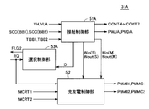
- FIG. 5 is a functional block diagram of the electrical system control unit 31 shown in FIG. With reference to FIG. 5, the electrical system control unit 31 includes a connection control unit 51, a charge / discharge control unit 52, and a selection control unit 53.
- Connection control unit 51 receives values of voltages VH, VLA, SOC (BB1), SOC (BB2), and temperatures TBB1 and TBB2. Connection control unit 51 outputs signals CONT4 to CONT7 and signal PWUA (or PWDA) for switching the selected sub power storage device and disconnecting the selected sub power storage device from converter 12B. The disconnection process of the selected sub power storage device will be described in detail later.
- the connection control unit 51 receives a flag FLG1 (disconnection permission flag) indicating permission of disconnection of the selected sub power storage device from the converter 12B.
- flag FLG1 disconnection permission flag
- flag FLG1 is turned on.
- flag FLG1 is turned off.
- the value of the flag FLG1 is switched between “1” and “0”. For example, the “ON state” corresponds to a state where the value of the flag FLG1 is 1, and the “OFF state” corresponds to a state where the value of the flag FLG1 is 0.
- connection control unit 51 further outputs Win (M), Wout (M), Win (S), and Wout (S).
- the charging / discharging control unit 52 performs charging / discharging control of the main power storage device and the sub power storage device when the electric vehicle 1 is traveling. Specifically, charge / discharge control unit 52 executes power distribution control between engine 4 and motor generators MG1, MG2. Therefore, the charge / discharge control unit 52 receives the motor current values MCRT1, MVCRT2, the regenerative brake request amount RQ, the input upper limit power Win (M), Win (S), and the output upper limit power Wout (M), Wout (S). Thus, charging / discharging of main power storage device BA and sub power storage devices BB1, BB2 is controlled in accordance with input upper limit power Win (M), Win (S) or output upper limit power Wout (M), Wout (S).
- the selection control unit 53 sets the flag FLG1 to the OFF state when receiving the regenerative brake request amount RQ.
- the selection control unit 53 sets the flag FLG1 to the on state.
- the connection control unit 51 performs the disconnection process of the selected sub power storage device until the flag FLG1 switches from the off state to the on state. Wait to do. That is, the separation process of the selected sub power storage device is prohibited during regenerative braking. Note that the disconnection process is executed after the regenerative braking is completed.
- FIG. 6 is a functional block diagram illustrating the configuration of the charge / discharge control unit 52 shown in FIG.
- charge / discharge control unit 52 includes a travel control unit 250, a total power calculation unit 260, and inverter control units 270 and 280.
- the total power calculation unit 260 calculates the total required power Pttl for the entire electric vehicle 1 based on the vehicle speed and the pedal operation (accelerator pedal). Note that the total required power Pttl can also include power (engine output) required for generating battery charging power by the motor generator MG1 in accordance with the vehicle situation.
- the traveling control unit 250 includes the input / output upper limit powers Win (M) and Wout (M) of the main power storage device BA, the input / output upper limit powers Win (S) and Wout (S) of the selected sub power storage device BB, and total power calculation.
- the total required power Pttl from the unit 260 and the regenerative brake request (RQ) when the brake pedal is operated are input.
- Traveling control unit 250 has a total input / output power of motor generators MG1 and MG2 that is limited in charging (Win (M) + Win (S)) and discharging (Wout (M) for main power storage device BA and selected sub power storage device BB. ) + Wout (S)), torque command values Tqcom1 and Tqcom2 as motor control commands are generated.
- the vehicle drive power by motor generator MG2 and the vehicle drive power by engine 4 are distributed so that total required power Pttl is ensured.
- the operation of the engine 4 is suppressed by maximizing the use of externally charged battery power, or the vehicle driving power by the engine 4 is set corresponding to a region where the engine 4 can operate with high efficiency. By this, high fuel consumption vehicle travel control is realized.
- the inverter control unit 270 generates control signals PWMI1 and PWMC1 for the inverter 14 based on the torque command value Tqcom1 and the motor current value MCRT1 of the motor generator MG1.
- inverter control unit 280 generates control signals PWMI2 and PWMC2 for inverter 22 based on torque command value Tqcom2 and motor current value MCRT2 of motor generator MG2.
- the traveling control unit 250 generates an engine control command according to the set value of the vehicle driving power by the set engine. Further, the operation of the engine 4 is controlled by a control device (engine ECU) (not shown) in accordance with the engine control command.
- the total required power Pttl is equal to or lower than the output upper limit power Wout (M) + Wout (S) for the entire battery. In some cases, the vehicle travels only by the vehicle driving power by the motor generator MG2 without operating the engine 4. On the other hand, when the total required power Pttl exceeds Wout (M) + Wout (S), the engine 4 is started.
- control device 30 drives between engine 4 and motor generator MG2 so that battery SOC is maintained at a predetermined target value.
- Control power power distribution That is, traveling control in which the engine 4 is more easily operated than in the EV mode is performed.
- control device 30 operates from EV mode to HV mode based on the average value of the SOC of main power storage device BA and the SOC of selected sub power storage device BB (hereinafter simply referred to as “average value of SOC”). It is determined whether or not it is necessary to switch the travel mode to. Specifically, when the average value of the SOC falls below a predetermined threshold value, control device 30 determines that switching from the EV mode to the HV mode is necessary.
- charge / discharge control is performed such that the power of the selected sub power storage device BB is preferentially used over the main power storage device BA. For this reason, when the SOC of the selected sub power storage device BB in use while the vehicle is traveling decreases, it becomes necessary to switch the selected sub power storage device BB. For example, when the battery BB1 is selected as the selected sub power storage device BB at the time of starting the vehicle, a connection switching process for disconnecting the battery BB1 from the converter 12B and connecting the battery BB2 as the new selected sub power storage device BB to the converter 12B is performed. It needs to be executed.
- the battery BB2 which is newly selected as the selected sub power storage device BB, generally has a higher output voltage than the battery BB1 used so far.
- the output voltage may be different between the main power storage device BA and the selected sub power storage device BB in use.
- the converter is arranged so that voltage VH is higher than the voltages (VBA, VBB) of the power storage device when both main power storage device and selected sub power storage device are used and when selected sub power storage device BB is switched.
- At least one of 12A and 12B performs a boosting operation. This can prevent a short circuit between the main power storage device and the selected sub power storage device.
- the lower limit value of voltage VH is also restricted from the viewpoint of controlling motor generators MG1 and MG2. Specifically, voltage VH is preferably higher than the induced voltage of motor generators MG1, MG2. Therefore, in practice, the voltage VH is controlled to be higher than both the lower limit value based on battery constraints and the lower limit value based on motor control.
- the voltage VH can be reduced from the motor control surface, and typically the boost in converters 12A and 12B is not required. Even so, it is necessary to boost the converters 12A and 12B in order to satisfy the lower limit value based on the battery constraint.
- FIG. 7 is a flowchart showing a schematic processing procedure of the disconnection process of the selected sub power storage device in the power system of the electric vehicle according to the embodiment of the present invention.
- 8 to 12 are flowcharts illustrating details of steps S100, S200, S300, S400, and S500 of FIG.
- the control device 30 (connection control unit 51) can repeatedly execute the control processing procedure according to the flowcharts shown in FIGS. 8 to 12 at a predetermined cycle by executing a predetermined program stored in advance at a predetermined cycle. Thereby, the separation process of the sub power storage device in the power supply system of the electric vehicle according to the embodiment of the present invention can be realized.
- step S ⁇ b> 100 control device 30 executes a separation determination process for the selected sub power storage device.
- steps S200 to S500 are executed.
- steps S200 to S500 are substantially not executed.
- step S200 control device 30 executes pre-separation boosting processing, and in step S300, the power limit is changed so that an excessive charge / discharge request is not generated for the power supply system during the sub-storage device disconnection period. Execute the process.
- step S400 control device 30 executes processing for actually disconnecting selected sub power storage device BB from converter 12B.
- step S500 control device 30 executes a boost stop process for stopping the boost process executed in step S200.
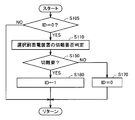
- FIG. 8 is a flowchart for explaining the details of the separation determination process (S100) of the selected sub power storage device shown in FIG.
- variable ID -1, 0 to 4 is set.
- the SOC of the sub power storage device in use falls below a predetermined determination value (threshold value) and there is no new sub power storage device that can be exchanged with the selected sub power storage device in use, It is determined that the power storage device needs to be disconnected.
- step S150 the control device 30 confirms the separation necessity determination result in step S110.
- control device 30 determines in step S155 whether flag FLG1 (separation permission flag) is on.
- flag FLG1 is on (when YES is determined in step S155)
- FIG. 9 is a flowchart for explaining the details of the pre-separation boosting process (S200) shown in FIG.
- ID 1 and a disconnection request for the selected sub power storage device BB is made and the disconnection process is started (when YES is determined in S205)
- the control device 30 performs the power supply line in step S210.
- a boost command for converter 12A is generated so as to boost voltage VH of PL2 to a predetermined voltage V1.
- predetermined voltage V1 is set to a voltage higher than the higher one of the output voltages of main power storage device BA and selected sub power storage device BB (for example, BB2).
- predetermined voltage V1 may be determined each time with a margin according to the output voltages of main power storage device BA and selected sub power storage device BB at that time.
- step S210 the control device 30 determines whether the voltage VH has reached the predetermined voltage V1 based on the detection value of the voltage sensor 13 in step S220. For example, when VH ⁇ V1 is maintained for a predetermined time, step S220 is determined as YES.
- the control device 30 advances the ID from 1 to 2.
- ID ⁇ 1 NO in S205
- the subsequent steps S210 to S230 are skipped.
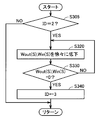
- step S200 the control device 30 executes a power limit changing process as shown in FIG.
- FIG. 10 is a flowchart for explaining the details of the power limit changing process (S300) shown in FIG.
- control device 30 gradually decreases the absolute values of input / output upper limit powers Win (S) and Wout (S) of selected sub power storage device BB in step S320.
- Wout (S) and Win (S) are gradually decreased toward 0 according to a predetermined constant rate.
- Wout (S) and Win (S) are decreased stepwise, the upper limit value of the torque (powering torque and regenerative torque) of motor generator MG2 decreases discontinuously. That is, there is a possibility that the torque of motor generator MG2 is suddenly limited. If such behavior of the motor generator MG2 is transmitted to the drive shaft, there is a possibility that an influence on vehicle behavior such as vehicle vibration may occur.
- the upper limit value of the torque of motor generator MG2 can be smoothly reduced by gradually decreasing the absolute values of Wout (S) and Win (S) according to a predetermined constant rate. Therefore, since the torque of motor generator MG2 can be avoided from being suddenly limited, the influence on the vehicle behavior as described above can be avoided.
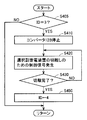
- control device 30 executes the sub power storage device disconnection process in step S400.
- FIG. 11 is a flowchart illustrating details of the sub-power storage device disconnection process (S400) shown in FIG.
- ID ⁇ 3 NO in S405
- the processes in subsequent steps S410 to S450 are skipped.
- control device 30 stops converter 12B as preparation for disconnection of the sub power storage device in step S410. That is, in converter 12B, IGBT elements Q1, Q2 are forcibly turned off in response to the shutdown command.
- Control device 30 generates a relay control signal for disconnecting the selected sub power storage device from converter 12B in step S420. For example, when sub power storage device BB2 is a selected sub power storage device, control device 30 generates relay control signals CONT5 and CONT7 to turn off relays SR2 and SR2G.
- control device 30 determines whether or not the separation is completed in step S430. When the disconnection is completed (YES in S430), control device 30 advances the ID from 3 to 4 in step S450.
- ID 4 indicates a state where disconnection between the sub power storage device and the converter 12B is completed.
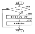
- step S400 When the separation process in step S400 is completed, the control device 30 executes the pressure increase stop process in step S500.
- FIG. 12 is a flowchart for explaining the details of the boost stop processing (S500) shown in FIG.
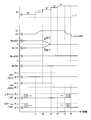
- FIG. 13 shows operation waveforms in the disconnection process of the selected sub power storage device in the power supply system for the electric vehicle according to the embodiment of the present invention described with reference to FIGS.
- disconnection determination processing based on the SOC of the currently selected sub power storage device is executed at a predetermined cycle.
- step S200 the pre-separation boosting process (step S200) is executed, and the voltage VH of the feed line PL2 is raised toward the predetermined voltage V1 by the converter 12A.
- the ID is changed from 1 to 2.
- converter 12B is controlled to stop charging / discharging of currently selected sub power storage device (battery BB1). Alternatively, converter 12B may shut down from time t1.
- the ID is changed from 2 to 3.
- the boosting by the converter 12A is allowed to stop.
- the switching operation of converter 12A is stopped after time t6. That is, after time t6, the upper arm of converter 12A is fixed on, while the lower arm of converter 12A is fixed off. In this case, voltage VH decreases to voltage VBA of main power storage device BA.
- the switching operation of converter 12A is continued even after time t6.
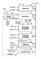
- Each functional block shown in FIG. 14 is realized by the control device 30 by software processing by execution of a predetermined program or a dedicated electronic circuit (hardware processing).
- disconnection determination unit 100 receives flag FLG1, and SOC (BB1) and SOC (BB2) indicating the state of charge of batteries BB1 and BB2. Isolation determination unit 100 determines whether or not the SOC of selected sub power storage device BB currently in use has decreased below a predetermined threshold when the variable ID shared between the functional blocks is 0. Further, disconnection determination unit 100 determines whether or not there remains a new sub power storage device that can be exchanged with the currently selected sub power storage device based on SOC (BB1) and SOC (BB2). The above determination processing is executed at a predetermined cycle.
- disconnection determination unit 100 selects the selected sub power storage device based on the state of charge SOC (BB) of the selected sub power storage device when no new sub power storage device that can be exchanged with the currently selected sub power storage device remains. It is determined whether or not it is necessary to disconnect power storage device BB from converter 12B. Disconnection determination unit 100 changes the ID from 0 to 1 when the selected sub power storage device needs to be disconnected and flag FLG1 is on. Thereby, a disconnection request for the selected sub power storage device is generated. When the flag FLG1 is off, the separation determination unit 100 sets the ID to -1. That is, the function of the separation determination unit 100 corresponds to the process of step S100 in FIG.
- BB state of charge SOC
- Converter control unit 200 generates control signals PWUA and PWDA for converter 12A based on voltages VH and VLA and voltage command value VHref so that voltage VH of power supply line PL2 becomes voltage command value VHref.
- the power limiting unit 120 sets the input / output upper limit power Win (S), Wout (S) of the selected sub power storage device BB.
- the input / output upper limit powers Win (S) and Wout (S) are the SOC (SOC (BB1) or SOC (BB2)), battery temperature (TBB1 or TBB2), and output of the battery selected as the selected sub power storage device BB. It is set based on the voltage (VBB1 or VBB2).
- Win (S) and Wout (S) reach 0, the ID is changed from 2 to 3.
- the power limiting unit 120 fixes the input / output upper limit powers Win (S) and Wout (S) to 0. That is, the function of the power limiting unit 120 corresponds to the processing in steps S320 to S340 in FIG.
- the power limiting unit 130 sets the input / output upper limit power Win (M) and Wout (M) of the main power storage device BA.
- Input / output upper limit power Win (M), Wout (M) is set based on SOC (BA), temperature TA, and voltage VBA of main power storage device BA.
- Converter control unit 200 generates control signal PWFA for fixing the upper arm of converter 12A to ON in response to a command from boost stop permission unit 150.
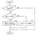
- FIG. 15 is a flowchart for explaining flag setting processing by the selection control unit 53 in FIG.
- the control device 30 selection control unit 53
- the control device 30 can repeatedly execute the control processing procedure according to the flowchart shown in FIG. 15 at a predetermined cycle by executing a predetermined program stored in advance at a predetermined cycle.
- selection control unit 53 determines whether or not regenerative braking of motor generator MG2 is being executed in step S10. The selection control unit 53 determines that the regenerative braking of the motor generator MG2 is being executed if the regenerative brake request amount RQ is a value other than 0, and if the regenerative brake request amount RQ is 0, the regenerative brake request amount RQ is determined. It is determined that braking is not being executed. If it is determined that regenerative braking is being executed (YES in step S10), the selection control unit 53 turns off the flag FLG1 (separation permission flag) in step S11. That is, selection control unit 53 prohibits disconnection of the selected sub power storage device. On the other hand, when it is determined that regenerative braking is not being executed (NO in step S10), selection control unit 53 turns on flag FLG1 in step S12. In other words, selection control unit 53 allows the selected sub power storage device to be disconnected.
- disconnection processing of the selected sub power storage device is prohibited during execution of the regenerative braking. Thereby, stable regenerative braking can be realized. This point will be described in detail.
- the braking force of the electric vehicle will decrease.
- a method for preventing such a problem a method of increasing the braking force by the hydraulic brake as the amount of execution of the regenerative brake decreases can be considered.
- the response of the hydraulic brake is lower than that of regenerative braking. Therefore, when the absolute value of the rate of change of the input / output upper limit power is larger than the rate of increase of the braking force by the hydraulic brake, for example, the driver may have the impression that the braking effectiveness has weakened. .
- the power corresponding to the regenerative brake request amount can be received by both the main power storage device and the selected sub power storage device. Therefore, the regenerative brake execution amount can be matched with the regenerative brake request amount. That is, braking control during normal braking is executed. Therefore, according to the first embodiment, it is possible to prevent the disconnection process of the sub power storage device from adversely affecting the braking of the electric vehicle.
- electrically powered vehicle 1 ⁇ / b> A according to Embodiment 2 of the present invention is different from electrically powered vehicle 1 in that control device 30 ⁇ / b> A is provided instead of control device 30.
- the configuration of the other part of the electric vehicle 1A is the same as the configuration of the corresponding part of the electric vehicle 1. Therefore, the control device 30A will be described in detail below.
- FIG. 17 is a functional block diagram illustrating a configuration of a control device 30A included in the electric vehicle according to the second embodiment. Note that each functional block shown in FIG. 17 is realized by execution of a predetermined program stored in advance by the control device 30A and / or arithmetic processing by an electronic circuit (hardware) in the control device 30A.
- control device 30A includes an electric system control unit 31A and a brake control unit 32A.
- Electric system control unit 31A turns off flag FLG2 during the disconnection process of the selected sub power storage device, and outputs flag FLG2 to brake control unit 32A.
- the electric system control unit 31A comprehensively controls the electric system of the electric vehicle 1A shown in FIG.
- the brake control unit 32A sets the regenerative brake request amount RQ to 0 in order to prohibit regenerative braking by the motor generator MG2.
- the brake control unit 32A may stop the generation of the regenerative brake request amount RQ when the flag FLG2 is off.
- the brake control unit 32A calculates the regenerative brake request amount RQ, and the calculated regenerative brake request amount RQ Is output to the electrical system control unit 31A.
- the regenerative brake request amount RQ is calculated based on, for example, the vehicle speed and the operation amount of the brake pedal 40 detected by the brake pedal stroke sensor 41.
- the electrical system control unit 31A generates a control signal PWMC2 (regeneration instruction) for controlling the inverter 22 based on the calculated regenerative brake request amount RQ, and outputs the control signal PWMC2 to the inverter 22.
- PWMC2 regeneration instruction
- the value of the flag FLG2 switches between “1” and “0”. For example, “ON state” corresponds to a state where the value of the flag FLG2 is 1, and “OFF state” corresponds to a state where the value of the flag FLG2 is 0.
- FIG. 18 is a functional block diagram illustrating the configuration of the electrical system control unit 31A shown in FIG. 18 and 5, electrical system control unit 31A is different from electrical system control unit 31 in that it includes connection control unit 51A and selection control unit 53A in place of connection control unit 51 and selection control unit 53, respectively. .
- the configuration of the other part of the electrical system control unit 31A is the same as the configuration of the corresponding part of the electrical system control unit 31.
- connection control unit 51A outputs the variable ID (-1, 0 to 4) to the selection control unit 53A.
- Selection control unit 53A determines whether or not the disconnection process of the selected sub power storage device is being executed based on the variable ID. If selection control unit 53A determines that the disconnection process of the selected sub power storage device is being executed, it turns off flag FLG2. On the other hand, when selection control unit 53A determines that the separation process of the selected sub power storage device is not executed based on the variable ID, it turns on flag FLG2.
- the procedure of the disconnection process of the selected sub power storage device according to the second embodiment is the same as the process procedure shown in the flowchart of FIG. However, the second embodiment is different from the first embodiment in the processing of step S100 (selected sub power storage device disconnection determination processing).
- FIG. 19 is a flowchart illustrating details of the separation determination process (S100) according to the second embodiment.
- the separation determination process according to the second embodiment is different from the separation determination process according to the first embodiment in that the process of step S ⁇ b> 155 is omitted.
- control device 30A connection control unit 51A
- connection control unit 51A differs from the connection control unit 51 shown in FIG. 14 in that the variable ID is output to the selection control unit 53A and the flag FLG1 is not input. It is the same. Therefore, the configuration of the functional part for disconnection processing of the selected sub power storage device in connection control unit 51A is the same as the configuration shown in FIG.
- FIG. 20 is a flowchart illustrating the processing of the selection control unit 53A illustrated in FIG.
- the selection control unit 53A can repeatedly execute the control processing procedure according to the flowchart shown in FIG. 20 at a predetermined cycle by executing a predetermined program stored in advance at a predetermined cycle.
- selection control unit 53A determines whether or not the selected sub power storage device is being disconnected based on the variable ID output from connection control unit 51A (step S20). Specifically, if the variable ID is ⁇ 1 or 0, selection control unit 53A determines that the selected sub power storage device disconnection process is not being executed. On the other hand, if the variable ID is any one of 1 to 4, selection control unit 53A determines that the selected sub power storage device disconnection process is being executed. If selection control unit 53A determines that the disconnection process of the selected sub power storage device is being executed (YES in step S20), it inhibits regenerative braking. That is, the selection control unit 53A turns off the flag FLG2. On the other hand, if selection control unit 53A determines that switching control of the selected sub power storage device is not being executed (NO determination in step S20), it permits regenerative braking. That is, the selection control unit 53A turns on the flag FLG2.
- FIG. 21 is a flowchart for explaining processing of the brake control unit 32A shown in FIG.
- Control device 30 can repeatedly execute a control processing procedure according to the flowchart shown in FIG. 21 at a predetermined cycle by executing a predetermined program stored in advance at a predetermined cycle.
- the brake control unit 32A determines whether or not the user operates the brake pedal 40 based on the detection result of the brake pedal stroke sensor 41 (step S30).
- the operation of the brake pedal 40 by the user means generation of a braking request. That is, in step S30, it is determined whether a braking request has occurred.
- step S31 When it is determined that the user has operated the brake pedal 40 (when YES is determined in step S30), the brake control unit 32A determines whether or not regenerative braking is permitted based on the flag FLG2 (step S31).
- flag FLG2 When flag FLG2 is on, that is, when regenerative braking is permitted (when YES is determined in step S31), brake control unit 32A calculates regenerative brake request amount RQ, and further by regenerative brake and hydraulic brake 42. Braking is executed (step S32).
- flag FLG2 is off, that is, when regenerative braking is prohibited (NO in step S31)
- brake control unit 32A sets regenerative brake request amount RQ to 0 and braking by hydraulic brake 42. Is executed (step S33).
- regenerative braking (power generation) by motor generator MG2 is prohibited during execution of the disconnection process of the selected sub power storage device.
- braking by only the hydraulic brake is executed. Therefore, it is possible to prevent the driver's impression about the responsiveness of the vehicle to the operation of the brake pedal from changing. Therefore, according to the second embodiment, it is possible to prevent the disconnection process of the sub power storage device from adversely affecting the braking of the electric vehicle.
- an electric vehicle equipped with a series / parallel type hybrid system capable of transmitting engine power divided into drive wheels and a generator by a power split mechanism is shown.
- the present invention is applied to, for example, a series hybrid vehicle, an electric vehicle, and a fuel cell vehicle in which an engine is used only for driving a generator and an axle driving force is generated only by a motor that uses electric power generated by the generator. Is also applicable. Since any of these vehicles can be regeneratively braked by a motor for driving the vehicle, the present invention is applicable.
Landscapes
- Engineering & Computer Science (AREA)
- Transportation (AREA)
- Mechanical Engineering (AREA)
- Power Engineering (AREA)
- Life Sciences & Earth Sciences (AREA)
- Sustainable Development (AREA)
- Sustainable Energy (AREA)
- Chemical & Material Sciences (AREA)
- Combustion & Propulsion (AREA)
- Manufacturing & Machinery (AREA)
- Chemical Kinetics & Catalysis (AREA)
- Electrochemistry (AREA)
- General Chemical & Material Sciences (AREA)
- Automation & Control Theory (AREA)
- Electric Propulsion And Braking For Vehicles (AREA)
- Hybrid Electric Vehicles (AREA)
Abstract
Description
本発明は、ある局面では、電動車両である。電動車両は、モータと、インバータと、主蓄電装置と、給電ラインと、第1の電圧変換器と、複数の副蓄電装置と、第2の電圧変換器と、接続部と、接続制御部と、走行制御部と、選択制御部とを備える。モータは、車両駆動パワーを発生可能であるととともに、回生制動を行なうことが可能である。インバータは、モータを制御する。給電ラインは、モータによる車両駆動パワーの発生のためにインバータに給電するとともに、モータの回生制動によってインバータから出力された電力を伝送する。第1の電圧変換器は、給電ラインと主蓄電装置との間に設けられ、双方向の電圧変換を行なうように構成される。複数の副蓄電装置は、互いに並列に設けられる。第2の電圧変換器は、複数の副蓄電装置と給電ラインとの間に設けられ、複数の副蓄電装置のうちの選択された副蓄電装置と給電ラインの間で双方向の電圧変換を行なうように構成される。接続部は、複数の副蓄電装置と第2の電圧変換器との間に設けられ、第2の電圧変換器に対する選択された副蓄電装置の接続および切離しを行なうように構成される。接続制御部は、選択された副蓄電装置と交換可能な新たな副蓄電装置が存在しないときに、選択された副蓄電装置の充電状態に基づいて、選択された副蓄電装置を第2の電圧変換器から切り離すための切離処理を実行するように構成される。走行制御部は、モータによる回生制動のためにインバータを制御する制動処理を実行するように構成される。選択制御部は、接続制御部による切離処理および走行制御部による制動処理のいずれか一方の処理の実行中に、他方の処理の実行を禁止するように構成される。
好ましくは、一方の処理は、切離処理である。他方の処理は、制動処理である。
好ましくは、一方の処理は、切離処理である。他方の処理は、制動処理である。
図1は、本発明の実施の形態1に係る電動車両の主たる構成を示す図である。
図2を参照して、インバータ14は、U相アーム15と、V相アーム16と、W相アーム17とを含む。U相アーム15、V相アーム16、およびW相アーム17は、給電ラインPL2と接地ラインSL2との間に並列に接続される。
図3を参照して、コンバータ12Aは、一方端が電源ラインPL1Aに接続されるリアクトルL1と、給電ラインPL2と接地ラインSL2との間に直列に接続されるIGBT素子Q1,Q2と、それぞれの逆並列ダイオードD1,D2とを含む。
図1を参照して、本発明の実施の形態2に係る電動車両1Aは、制御装置30に代えて制御装置30Aを備える点において電動車両1と異なる。なお電動車両1Aの他の部分の構成は電動車両1の対応する部分の構成と同様である。したがって、以下では制御装置30Aについて詳細に説明する。
図20は、図18に示した選択制御部53Aの処理を説明するフローチャートである。選択制御部53Aは、予め記憶した所定プログラムを所定周期で実行することによって、図20に示されるフローチャートに従う制御処理手順を所定周期で繰り返し実行することができる。
Claims (12)
- [規則91に基づく訂正 24.02.2010]
車両駆動パワーを発生可能であるととともに、回生制動を行なうことが可能なモータ(MG2)と、
前記モータ(MG2)を制御するためのインバータ(22)と、
主蓄電装置(BA)と、
前記モータ(MG2)による前記車両駆動パワーの発生のために前記インバータ(22)に給電するとともに、前記モータ(MG2)の前記回生制動によって前記インバータ(22)から出力された電力を伝送するための給電ライン(PL2)と、
前記給電ライン(PL2)と前記主蓄電装置(BA)との間に設けられ、双方向の電圧変換を行なうように構成された第1の電圧変換器(12A)と、
互いに並列に設けられた複数の副蓄電装置(BB1,BB2)と、
前記複数の副蓄電装置(BB1,BB2)と前記給電ライン(PL2)との間に設けられ、前記複数の副蓄電装置(BB1,BB2)のうちの選択された副蓄電装置と前記給電ライン(PL2)の間で双方向の電圧変換を行なうように構成された第2の電圧変換器(12B)と、
前記複数の副蓄電装置(BB1,BB2)と前記第2の電圧変換器(12B)との間に設けられ、前記第2の電圧変換器(12B)に対する前記選択された副蓄電装置の接続および切離しを行なうように構成された接続部(39B)と、
前記選択された副蓄電装置と交換可能な新たな副蓄電装置が存在しないときに、前記選択された副蓄電装置の充電状態に基づいて、前記選択された副蓄電装置を前記第2の電圧変換器(12B)から切り離すための切離処理を実行するように構成された接続制御部(51,51A)と、
前記モータ(MG2)による前記回生制動のために前記インバータ(22)を制御する制動処理を実行するように構成された走行制御部(250)と、
前記接続制御部による前記切離処理および前記走行制御部(250)による前記制動処理のいずれか一方の処理の実行中に、他方の処理の実行を禁止するように構成された選択制御部(53,53A)とを備える、電動車両。 - 前記切離処理は、
前記選択された副蓄電装置の前記充電状態に基づいて、前記選択された副蓄電装置を前記第2の電圧変換器(12B)から切り離すことの要否を判定する第1の処理と、
前記選択された副蓄電装置の切離が必要と判断されたときに、前記給電ライン(PL2)の電圧(VH)が、前記主蓄電装置(BA)の出力電圧および前記選択された副蓄電装置の出力電圧よりも高い所定の電圧となるように前記第1の電圧変換器(12A)を制御する第2の処理と、
前記給電ラインの電圧が前記所定の電圧に達した後に、前記選択副蓄電装置による入出力電力上限値(Win(S),Wout(S))を零に設定する第3の処理と、
前記入出力電力上限値(Win(S),Wout(S))が零に設定されたことに応じて、前記選択された副蓄電装置が前記第2の電圧変換器(12B)から切り離されるように前記接続部(39B)を制御する第4の処理とを含み、
前記接続制御部(51,51A)は、
前記第1の処理を実行するように構成された切離判定部(100)と、
前記第2の処理を実行するように構成された昇圧指示部(110)と、
前記第3の処理を実行するように構成された電力制限部(120)と、
前記第4の処理を実行するように構成された切離制御部(140)とを含む、請求の範囲第1項に記載の電動車両。 - 前記電力制限部(120)は、前記第3の処理の実行時に前記入出力電力上限値を零まで漸減するように構成される、請求の範囲第2項に記載の電動車両。
- 前記一方の処理は、前記制動処理であり、
前記他方の処理は、前記切離処理である、請求の範囲第1項に記載の電動車両。 - 前記一方の処理は、前記切離処理であり、
前記他方の処理は、前記制動処理である、請求の範囲第1項に記載の電動車両。 - 前記電動車両は、
前記モータ(MG2)による前記回生制動とは独立に前記電動車両の制動力を発生可能な油圧ブレーキ(42)と、
前記切離処理の実行中に前記電動車両の制動要求が生じた場合に、前記油圧ブレーキ(42)のみによる制動を実行するように構成されたブレーキ制御部(32A)とをさらに備える、請求の範囲第5項に記載の電動車両。 - 電動車両の制御方法であって、前記電動車両は、
車両駆動パワーを発生可能であるととともに、回生制動を行なうことが可能なモータ(MG2)と、
前記モータ(MG2)を制御するためのインバータ(22)と、
主蓄電装置(BA)と、
前記モータ(MG2)による前記車両駆動パワーの発生のために前記インバータ(22)に給電するとともに、前記モータ(MG2)の前記回生制動によって前記インバータ(22)から出力された電力を伝送するための給電ライン(PL2)と、
前記給電ライン(PL2)と前記主蓄電装置(BA)との間に設けられ、双方向の電圧変換を行なうように構成された第1の電圧変換器(12A)と、
互いに並列に設けられた複数の副蓄電装置(BB1,BB2)と、
前記複数の副蓄電装置(BB1,BB2)と前記給電ライン(PL2)との間に設けられ、前記複数の副蓄電装置(BB1,BB2)のうちの選択された副蓄電装置と前記給電ライン(PL2)の間で双方向の電圧変換を行なうように構成された第2の電圧変換器(12B)と、
前記複数の副蓄電装置(BB1,BB2)と前記第2の電圧変換器(12B)との間に設けられ、前記第2の電圧変換器(12B)に対する前記選択された副蓄電装置の接続および切離しを行なうように構成された接続部(39B)と、
前記インバータ(22)および前記接続部(39B)を制御するように構成された制御装置(30,30A)とを備え、
前記制御方法は、
前記選択された副蓄電装置と交換可能な新たな副蓄電装置が存在しないときに、前記選択された副蓄電装置の充電状態に基づいて、前記選択された副蓄電装置を前記第2の電圧変換器(12B)から切り離すための切離処理を実行するステップ(S100-S500)と、
前記モータ(MG2)による前記回生制動のために前記インバータ(22)を制御する制動処理を実行するステップ(S10,S22)と、
前記切離処理および前記制動処理のいずれか一方の処理の実行中に、他方の処理の実行を禁止するステップ(S10-S12,S20-S22)とを備える、電動車両の制御方法。 - 前記切離処理は、
前記選択された副蓄電装置の前記充電状態に基づいて、前記選択された副蓄電装置を前記第2の電圧変換器(12B)から切り離すことの要否を判定する第1の処理と、
前記選択された副蓄電装置の切離が必要と判断されたときに、前記給電ライン(PL2)の電圧(VH)が、前記主蓄電装置(BA)の出力電圧および前記選択された副蓄電装置の出力電圧よりも高い所定の電圧となるように前記第1の電圧変換器(12A)を制御する第2の処理と、
前記給電ラインの電圧が前記所定の電圧に達した後に、前記選択副蓄電装置による入出力電力上限値(Win(S),Wout(S))を零に設定する第3の処理と、
前記入出力電力上限値が零に設定されたときに、前記選択された副蓄電装置が前記第2の電圧変換器から切り離されるように前記接続部を制御する第4の処理とを含み、
前記切離処理を実行するステップ(S100-S500)は、
前記第1の処理を実行するステップ(S100)と、
前記第2の処理を実行するステップ(S200)と、
前記第3の処理を実行するステップ(S300)と、
前記第4の処理を実行するステップ(S400)とを含む、請求の範囲第7項に記載の電動車両の制御方法。 - 前記第3の処理を実行するステップは、
前記入出力電力上限値を零まで漸減するステップ(S320,S330)を含む、請求の範囲第8項に記載の電動車両の制御方法。 - 前記一方の処理は、前記制動処理であり、
前記他方の処理は、前記切離処理である、請求の範囲第7項に記載の電動車両の制御方法。 - 前記一方の処理は、前記切離処理であり、
前記他方の処理は、前記制動処理である、請求の範囲第7項に記載の電動車両の制御方法。 - 前記電動車両は、
前記モータ(MG2)による前記回生制動とは独立に前記電動車両の制動力を発生可能な油圧ブレーキ(42)をさらに備え、
前記制御装置(30)は、前記油圧ブレーキ(42)による制動を制御するように構成され、
前記制御方法は、
前記切離処理の実行中に前記電動車両の制動要求が生じた場合に、前記油圧ブレーキ(42)のみによる制動を実行するステップ(S30,S31,S33)をさらに備える、請求の範囲第11項に記載の電動車両の制御方法。
Priority Applications (5)
| Application Number | Priority Date | Filing Date | Title |
|---|---|---|---|
| US13/260,487 US8509978B2 (en) | 2009-06-10 | 2009-06-10 | Electric powered vehicle and control method for the same |
| PCT/JP2009/060591 WO2010143280A1 (ja) | 2009-06-10 | 2009-06-10 | 電動車両および電動車両の制御方法 |
| CN200980159834.4A CN102802999B (zh) | 2009-06-10 | 2009-06-10 | 电动车辆及其电动车辆的控制方法 |
| EP09845805.2A EP2444269B1 (en) | 2009-06-10 | 2009-06-10 | Electric vehicle and method for controlling electric vehicle |
| JP2011518175A JP5029784B2 (ja) | 2009-06-10 | 2009-06-10 | 電動車両および電動車両の制御方法 |
Applications Claiming Priority (1)
| Application Number | Priority Date | Filing Date | Title |
|---|---|---|---|
| PCT/JP2009/060591 WO2010143280A1 (ja) | 2009-06-10 | 2009-06-10 | 電動車両および電動車両の制御方法 |
Publications (1)
| Publication Number | Publication Date |
|---|---|
| WO2010143280A1 true WO2010143280A1 (ja) | 2010-12-16 |
Family
ID=43308548
Family Applications (1)
| Application Number | Title | Priority Date | Filing Date |
|---|---|---|---|
| PCT/JP2009/060591 Ceased WO2010143280A1 (ja) | 2009-06-10 | 2009-06-10 | 電動車両および電動車両の制御方法 |
Country Status (5)
| Country | Link |
|---|---|
| US (1) | US8509978B2 (ja) |
| EP (1) | EP2444269B1 (ja) |
| JP (1) | JP5029784B2 (ja) |
| CN (1) | CN102802999B (ja) |
| WO (1) | WO2010143280A1 (ja) |
Cited By (4)
| Publication number | Priority date | Publication date | Assignee | Title |
|---|---|---|---|---|
| JP2012161216A (ja) * | 2011-02-03 | 2012-08-23 | Toyota Motor Corp | 車両および車両用制御方法 |
| JP2012249365A (ja) * | 2011-05-25 | 2012-12-13 | Shin Kobe Electric Mach Co Ltd | リチウムイオン電池を搭載した電動カート及び電動カート用リチウムイオン電池の充電方法 |
| JP2017147829A (ja) * | 2016-02-16 | 2017-08-24 | 本田技研工業株式会社 | 電力供給システム及び輸送機器、並びに、電力伝送システムの制御方法 |
| TWI606670B (zh) * | 2016-09-30 | 2017-11-21 | 尼克森微電子股份有限公司 | 制動能源回收模組 |
Families Citing this family (21)
| Publication number | Priority date | Publication date | Assignee | Title |
|---|---|---|---|---|
| JP5099229B2 (ja) * | 2008-10-31 | 2012-12-19 | トヨタ自動車株式会社 | ハイブリッド車両およびその制御方法 |
| WO2010050045A1 (ja) * | 2008-10-31 | 2010-05-06 | トヨタ自動車株式会社 | 電動車両の電源システム、電動車両および電動車両の制御方法 |
| EP2441616A4 (en) | 2009-06-10 | 2017-05-17 | Toyota Jidosha Kabushiki Kaisha | Hybrid vehicle and control method thereof |
| KR101229441B1 (ko) * | 2011-03-18 | 2013-02-06 | 주식회사 만도 | 배터리 충전 장치 |
| JP5781854B2 (ja) * | 2011-07-19 | 2015-09-24 | 日立オートモティブシステムズ株式会社 | 車両制御装置 |
| EP2811549B1 (en) * | 2013-06-07 | 2018-09-19 | Autoliv Development AB | Over-current responsive device |
| US10046646B2 (en) * | 2013-09-06 | 2018-08-14 | Samsung Sdi Co., Ltd. | Power conversion system for electric vehicles |
| US10202042B2 (en) * | 2013-10-04 | 2019-02-12 | Samsung Sdi Co., Ltd. | Electric vehicle power conversion system |
| KR101875996B1 (ko) * | 2015-06-17 | 2018-07-06 | 현대자동차주식회사 | 친환경 차량용 양방향 컨버터 제어 장치 및 방법 |
| US9800188B2 (en) * | 2015-09-15 | 2017-10-24 | Regal Beloit America, Inc. | Hybrid drive circuit for variable speed induction motor |
| KR101776403B1 (ko) * | 2015-10-08 | 2017-09-07 | 현대자동차주식회사 | 환경차량용 배터리충전기의 운전 방법 |
| KR101755984B1 (ko) * | 2016-02-12 | 2017-07-20 | 현대자동차주식회사 | Dct 탑재 하이브리드 차량의 제어방법 |
| JP6520796B2 (ja) * | 2016-04-08 | 2019-05-29 | 株式会社デンソー | 回転電機の制御装置 |
| WO2019058821A1 (ja) * | 2017-09-22 | 2019-03-28 | 株式会社村田製作所 | 蓄電装置 |
| JP6888512B2 (ja) * | 2017-10-16 | 2021-06-16 | トヨタ自動車株式会社 | ハイブリッド自動車 |
| JP6919492B2 (ja) * | 2017-10-18 | 2021-08-18 | トヨタ自動車株式会社 | 燃料電池車両および燃料電池車両の制御方法 |
| DE102018203915A1 (de) * | 2018-03-14 | 2019-09-19 | Audi Ag | HV-Energiespeicher |
| KR102565333B1 (ko) * | 2018-12-12 | 2023-08-16 | 현대자동차주식회사 | 모터 구동 시스템을 이용한 충전 시스템의 제어 장치 |
| JP7622349B2 (ja) * | 2020-03-27 | 2025-01-28 | 株式会社Gsユアサ | 蓄電装置 |
| JP7408594B2 (ja) * | 2021-03-25 | 2024-01-05 | 本田技研工業株式会社 | 車両及び制御装置 |
| US20250388089A1 (en) * | 2024-06-25 | 2025-12-25 | Fca Us Llc | Electrical braking system for electrified vehicle |
Citations (6)
| Publication number | Priority date | Publication date | Assignee | Title |
|---|---|---|---|---|
| JP2003209969A (ja) | 2001-12-06 | 2003-07-25 | General Motors Corp <Gm> | 電動モータ電源管理システム |
| JP2004312863A (ja) * | 2003-04-07 | 2004-11-04 | Hitachi Ltd | 鉄道車両用電力変換器の制御装置 |
| JP2004359032A (ja) * | 2003-06-03 | 2004-12-24 | Sony Corp | 電動アシスト自転車及び電動車両 |
| JP2008109840A (ja) | 2006-09-28 | 2008-05-08 | Toyota Motor Corp | 電源システムおよびそれを備えた車両、電源システムの制御方法ならびにその制御方法をコンピュータに実行させるためのプログラムを記録したコンピュータ読取可能な記録媒体 |
| JP2008167620A (ja) | 2007-01-04 | 2008-07-17 | Toyota Motor Corp | 車両の電源装置および車両 |
| JP2008220084A (ja) * | 2007-03-06 | 2008-09-18 | Toyota Motor Corp | 車両の電源装置および車両の電源装置の制御方法 |
Family Cites Families (3)
| Publication number | Priority date | Publication date | Assignee | Title |
|---|---|---|---|---|
| JP4131395B2 (ja) * | 2003-02-21 | 2008-08-13 | 株式会社デンソー | 車両用回生制動装置 |
| JP2006174543A (ja) * | 2004-12-13 | 2006-06-29 | Honda Motor Co Ltd | ハイブリッド車両における回生電力制御装置 |
| JP4285458B2 (ja) * | 2005-08-08 | 2009-06-24 | トヨタ自動車株式会社 | 車両の電源装置およびその制御方法 |
-
2009
- 2009-06-10 WO PCT/JP2009/060591 patent/WO2010143280A1/ja not_active Ceased
- 2009-06-10 JP JP2011518175A patent/JP5029784B2/ja active Active
- 2009-06-10 EP EP09845805.2A patent/EP2444269B1/en not_active Not-in-force
- 2009-06-10 CN CN200980159834.4A patent/CN102802999B/zh not_active Expired - Fee Related
- 2009-06-10 US US13/260,487 patent/US8509978B2/en active Active
Patent Citations (6)
| Publication number | Priority date | Publication date | Assignee | Title |
|---|---|---|---|---|
| JP2003209969A (ja) | 2001-12-06 | 2003-07-25 | General Motors Corp <Gm> | 電動モータ電源管理システム |
| JP2004312863A (ja) * | 2003-04-07 | 2004-11-04 | Hitachi Ltd | 鉄道車両用電力変換器の制御装置 |
| JP2004359032A (ja) * | 2003-06-03 | 2004-12-24 | Sony Corp | 電動アシスト自転車及び電動車両 |
| JP2008109840A (ja) | 2006-09-28 | 2008-05-08 | Toyota Motor Corp | 電源システムおよびそれを備えた車両、電源システムの制御方法ならびにその制御方法をコンピュータに実行させるためのプログラムを記録したコンピュータ読取可能な記録媒体 |
| JP2008167620A (ja) | 2007-01-04 | 2008-07-17 | Toyota Motor Corp | 車両の電源装置および車両 |
| JP2008220084A (ja) * | 2007-03-06 | 2008-09-18 | Toyota Motor Corp | 車両の電源装置および車両の電源装置の制御方法 |
Non-Patent Citations (1)
| Title |
|---|
| See also references of EP2444269A4 |
Cited By (5)
| Publication number | Priority date | Publication date | Assignee | Title |
|---|---|---|---|---|
| JP2012161216A (ja) * | 2011-02-03 | 2012-08-23 | Toyota Motor Corp | 車両および車両用制御方法 |
| JP2012249365A (ja) * | 2011-05-25 | 2012-12-13 | Shin Kobe Electric Mach Co Ltd | リチウムイオン電池を搭載した電動カート及び電動カート用リチウムイオン電池の充電方法 |
| JP2017147829A (ja) * | 2016-02-16 | 2017-08-24 | 本田技研工業株式会社 | 電力供給システム及び輸送機器、並びに、電力伝送システムの制御方法 |
| TWI606670B (zh) * | 2016-09-30 | 2017-11-21 | 尼克森微電子股份有限公司 | 制動能源回收模組 |
| US10668815B2 (en) | 2016-09-30 | 2020-06-02 | Niko Semiconductor Co., Ltd. | Brake energy recovery module |
Also Published As
| Publication number | Publication date |
|---|---|
| EP2444269A4 (en) | 2013-04-10 |
| US20120022738A1 (en) | 2012-01-26 |
| EP2444269A1 (en) | 2012-04-25 |
| JP5029784B2 (ja) | 2012-09-19 |
| CN102802999A (zh) | 2012-11-28 |
| JPWO2010143280A1 (ja) | 2012-11-22 |
| US8509978B2 (en) | 2013-08-13 |
| EP2444269B1 (en) | 2016-11-30 |
| CN102802999B (zh) | 2014-02-26 |
Similar Documents
| Publication | Publication Date | Title |
|---|---|---|
| JP5029784B2 (ja) | 電動車両および電動車両の制御方法 | |
| JP5141773B2 (ja) | 電動車両および電動車両の制御方法 | |
| JP5024454B2 (ja) | 電動車両の電源システムおよびその制御方法 | |
| JP5141772B2 (ja) | 電動車両の電源システムおよびその制御方法 | |
| JP5099230B2 (ja) | 電動車両の電源システムおよびその制御方法 | |
| JP4798305B2 (ja) | 電動車両の電源システムおよびその制御方法 | |
| JP5152408B2 (ja) | ハイブリッド車両およびその制御方法 | |
| JP4888600B2 (ja) | 電動車両の電源システム、電動車両および電動車両の制御方法 | |
| JP4743342B2 (ja) | 電動車両の電源システム、電動車両および電動車両の電源システムの制御方法 | |
| JP5099229B2 (ja) | ハイブリッド車両およびその制御方法 | |
| JP5229120B2 (ja) | 電動車両の電源システムおよび電動車両 | |
| JP2011172400A (ja) | 電動車両の電源システムおよび電動車両 |
Legal Events
| Date | Code | Title | Description |
|---|---|---|---|
| WWE | Wipo information: entry into national phase |
Ref document number: 200980159834.4 Country of ref document: CN |
|
| 121 | Ep: the epo has been informed by wipo that ep was designated in this application |
Ref document number: 09845805 Country of ref document: EP Kind code of ref document: A1 |
|
| WWE | Wipo information: entry into national phase |
Ref document number: 13260487 Country of ref document: US |
|
| WWE | Wipo information: entry into national phase |
Ref document number: 2011518175 Country of ref document: JP |
|
| NENP | Non-entry into the national phase |
Ref country code: DE |
|
| REEP | Request for entry into the european phase |
Ref document number: 2009845805 Country of ref document: EP |
|
| WWE | Wipo information: entry into national phase |
Ref document number: 2009845805 Country of ref document: EP |