WO2010137533A1 - 表面処理蛍光体粒子の製造方法及び表面処理蛍光体粒子 - Google Patents
表面処理蛍光体粒子の製造方法及び表面処理蛍光体粒子 Download PDFInfo
- Publication number
- WO2010137533A1 WO2010137533A1 PCT/JP2010/058663 JP2010058663W WO2010137533A1 WO 2010137533 A1 WO2010137533 A1 WO 2010137533A1 JP 2010058663 W JP2010058663 W JP 2010058663W WO 2010137533 A1 WO2010137533 A1 WO 2010137533A1
- Authority
- WO
- WIPO (PCT)
- Prior art keywords
- phosphor particles
- phosphor
- treated
- aqueous solution
- particles
- Prior art date
- Legal status (The legal status is an assumption and is not a legal conclusion. Google has not performed a legal analysis and makes no representation as to the accuracy of the status listed.)
- Ceased
Links
Images


Classifications
-
- C—CHEMISTRY; METALLURGY
- C09—DYES; PAINTS; POLISHES; NATURAL RESINS; ADHESIVES; COMPOSITIONS NOT OTHERWISE PROVIDED FOR; APPLICATIONS OF MATERIALS NOT OTHERWISE PROVIDED FOR
- C09K—MATERIALS FOR MISCELLANEOUS APPLICATIONS, NOT PROVIDED FOR ELSEWHERE
- C09K11/00—Luminescent materials, e.g. electroluminescent or chemiluminescent
- C09K11/08—Luminescent materials, e.g. electroluminescent or chemiluminescent containing inorganic luminescent materials
- C09K11/77—Luminescent materials, e.g. electroluminescent or chemiluminescent containing inorganic luminescent materials containing rare earth metals
- C09K11/7728—Luminescent materials, e.g. electroluminescent or chemiluminescent containing inorganic luminescent materials containing rare earth metals containing europium
- C09K11/7734—Aluminates
-
- C—CHEMISTRY; METALLURGY
- C09—DYES; PAINTS; POLISHES; NATURAL RESINS; ADHESIVES; COMPOSITIONS NOT OTHERWISE PROVIDED FOR; APPLICATIONS OF MATERIALS NOT OTHERWISE PROVIDED FOR
- C09K—MATERIALS FOR MISCELLANEOUS APPLICATIONS, NOT PROVIDED FOR ELSEWHERE
- C09K11/00—Luminescent materials, e.g. electroluminescent or chemiluminescent
- C09K11/02—Use of particular materials as binders, particle coatings or suspension media therefor
- C09K11/025—Use of particular materials as binders, particle coatings or suspension media therefor non-luminescent particle coatings or suspension media
-
- C—CHEMISTRY; METALLURGY
- C09—DYES; PAINTS; POLISHES; NATURAL RESINS; ADHESIVES; COMPOSITIONS NOT OTHERWISE PROVIDED FOR; APPLICATIONS OF MATERIALS NOT OTHERWISE PROVIDED FOR
- C09K—MATERIALS FOR MISCELLANEOUS APPLICATIONS, NOT PROVIDED FOR ELSEWHERE
- C09K11/00—Luminescent materials, e.g. electroluminescent or chemiluminescent
- C09K11/08—Luminescent materials, e.g. electroluminescent or chemiluminescent containing inorganic luminescent materials
- C09K11/59—Luminescent materials, e.g. electroluminescent or chemiluminescent containing inorganic luminescent materials containing silicon
- C09K11/592—Chalcogenides
- C09K11/595—Chalcogenides with zinc or cadmium
-
- C—CHEMISTRY; METALLURGY
- C09—DYES; PAINTS; POLISHES; NATURAL RESINS; ADHESIVES; COMPOSITIONS NOT OTHERWISE PROVIDED FOR; APPLICATIONS OF MATERIALS NOT OTHERWISE PROVIDED FOR
- C09K—MATERIALS FOR MISCELLANEOUS APPLICATIONS, NOT PROVIDED FOR ELSEWHERE
- C09K11/00—Luminescent materials, e.g. electroluminescent or chemiluminescent
- C09K11/08—Luminescent materials, e.g. electroluminescent or chemiluminescent containing inorganic luminescent materials
- C09K11/77—Luminescent materials, e.g. electroluminescent or chemiluminescent containing inorganic luminescent materials containing rare earth metals
- C09K11/7728—Luminescent materials, e.g. electroluminescent or chemiluminescent containing inorganic luminescent materials containing rare earth metals containing europium
- C09K11/77342—Silicates
Definitions
- the present invention relates to a method for producing surface-treated phosphor particles and surface-treated phosphor particles.
- an ultraviolet excitation light emitting element for example, a backlight for a liquid crystal display, a three-wavelength fluorescent lamp, a high load fluorescent lamp, etc.
- whose excitation source of the phosphor is ultraviolet
- Vacuum ultraviolet-excited light emitting device for example, plasma display panel, rare gas lamp, etc.
- white LED which is light emitted from a blue LED or ultraviolet LED as an excitation source
- electron beam excited light-emitting device whose excitation source is an electron beam for example, a cathode ray tube, a field emission display, a surface electric field display, etc.
- a light emitting element X-ray imaging apparatus etc. whose excitation source is X-rays, etc.
- the phosphor emits light when irradiated with the excitation source as described above.
- characteristics such as luminance, color purity, durability, charging characteristics, and particle diameter
- an optimum phosphor is selected according to the environment in which it is used.
- BaMgAl 10 O 17 : Eu 2+ (commonly referred to as BAM) or CaMgSi 2 O 6 : Eu 2+ (commonly known as CMS) has been known as a blue phosphor for ultraviolet-excited light-emitting elements and vacuum ultraviolet-excited light-emitting elements. .
- LaPO 4 : Ce 3+ , Tb 3+ and Zn 2 SiO 4 : Mn 2+ are known as green phosphors
- Y 2 O 3 : Eu 3+ and (Y, Gd) BO 3 : Eu 3+ are known as red phosphors. Yes.
- a phosphor When such a phosphor is used in a device such as a display, usually, phosphor particles are mixed with a solvent or a binder to prepare a slurry or paste, and these are applied or printed on a portion to be a light emitting surface of a substrate, Thereafter, the fluorescent layer is formed by a method of removing the solvent and the binder by drying and heating.
- the phosphor when the phosphor receives a thermal history, the luminance of the phosphor may decrease. This phenomenon is generally referred to as phosphor deterioration due to firing.
- the brightness of the phosphor that continues to receive high energy such as ultraviolet light and vacuum ultraviolet light that is the excitation source will decrease, or the emission color (emission wavelength) of the phosphor will decrease. Sometimes it changes. These phenomena are generally referred to as long-term deterioration of the phosphor, lifetime problems, and the like.
- a method of coating the surface of the phosphor particles with a material having excellent durability may be employed (see, for example, Patent Documents 1 to 5).
- the material used for coating include nitrides, fluorides, carbonates, complex oxides, and organic substances in addition to simple oxides such as Al 2 O 3 and SiO 2 .
- the present invention makes it possible to sufficiently suppress the decrease in luminance due to the thermal history received in the stage of manufacturing various devices using phosphor particles while maintaining the initial luminance sufficiently high. Is the main purpose.
- the present invention provides phosphor particles and their surfaces in a dispersion obtained by mixing an aqueous solution containing lanthanum and an aqueous solution containing phosphoric acid in the presence of the phosphor particles.
- a method for producing surface-treated phosphor particles comprising a step of forming surface-treated phosphor particles having lanthanum phosphate attached to the surface.
- lanthanum phosphate is generated by a coprecipitation reaction, and lanthanum phosphate adheres to the surface of the phosphor particles, whereby surface-treated phosphor particles can be produced without firing. Therefore, the initial luminance of the phosphor particles can be maintained at a sufficiently high level. Furthermore, according to the present surface-treated phosphor particles, a decrease in luminance due to a thermal history received at the stage of manufacturing various devices including the phosphor particles is sufficiently suppressed.
- the phosphor particles are (Ba 1-xz Sr x Eu z ) MgAl 10 O 17 (x is 0 ⁇ x ⁇ 0.5, z is 0.01 ⁇ z ⁇ 0. 2), (Ca 1-yz Sr y Eu z ) MgSi 2 O 6 (y satisfies 0 ⁇ y ⁇ 1, z satisfies 0.001 ⁇ z ⁇ 0.1) , Y + z ⁇ 1, or a phosphor represented by (Zn 2 ⁇ w Mn w ) SiO 4 (w satisfies 0.001 ⁇ w ⁇ 0.1). It is preferable.
- the phosphor particles contain BaMgAl 10 O 17 : Eu 2+ , there is a problem particularly in the firing deterioration and long-term deterioration of the phosphor.
- the phosphor particles contain a phosphor represented by Ca 1-y Sr y MgSi 2 O 6 : Eu 2+ (y is 0 to 1), a problem of so-called temperature quenching tends to occur.
- the temperature of the device rises due to incident energy, heat generation of an electronic circuit, and the like, and the temperature of the phosphor rises accordingly, and the luminance of the device may decrease.
- Such a phenomenon is called temperature quenching of the phosphor, and this causes a change in the color of the display and illumination.
- the phosphor particles contain a phosphor represented by Zn 2 SiO 4 : Mn 2+ , a decrease in luminance due to mercury adsorption tends to be a problem.
- the present invention is also useful in that these problems can be avoided.
- the production method of the present invention preferably further comprises a step of recovering the surface-treated phosphor particles from the dispersion by a method in which the surface-treated phosphor particles are not heated to 200 ° C. or higher.
- the surface-treated phosphor particles are used for manufacturing a device without firing at a high temperature of about 300 to 600 ° C., for example. be able to. As a result, the initial luminance reduction of the phosphor particles can be particularly effectively prevented.
- the present invention also provides phosphor particles, a lanthanum phosphate adhering to the surface of the phosphor particles by a method of mixing an aqueous solution containing lanthanum and an aqueous solution containing phosphoric acid in the presence of the phosphor particles.
- a surface-treated phosphor particle is provided.
- the luminance is sufficiently lowered due to the thermal history received in the production of various devices using the phosphor particles. It is possible to suppress.
- the phosphor particles are (Ba 1-xz Sr x Eu z ) MgAl 10 O 17 (x is 0 ⁇ x ⁇ 0.5, z is 0.01 ⁇ (Ca 1 ⁇ yz Sr y Eu z ) MgSi 2 O 6 (y is 0 ⁇ y ⁇ 1, z is 0.001 ⁇ z ⁇ 0). .1 and y + z ⁇ 1), or (Zn 2 ⁇ w Mn w ) SiO 4 (w satisfies 0.001 ⁇ w ⁇ 0.1). It is preferable to contain a phosphor.
- the mass ratio of lanthanum phosphate based on the mass of the phosphor particles is preferably 0.01 to 5% by mass.
- the mass ratio of the phosphor particles decreases and the relative luminance decreases, so the mass ratio of lanthanum phosphate based on the mass of the phosphor particles is within the above range. preferable.
- lanthanum phosphate is generated by a coprecipitation reaction and adheres to the surface of the phosphor particles, thereby producing the surface-treated phosphor particles without performing a firing treatment. be able to. Therefore, the initial luminance of the phosphor particles can be maintained at a sufficiently high level. Furthermore, according to the present surface-treated phosphor particles, a decrease in luminance due to a thermal history received at the stage of manufacturing various devices including the phosphor particles is sufficiently suppressed.
- 2 is an electron micrograph of surface-treated phosphor particles.
- the phosphor particles and the surface thereof are adhered in a dispersion obtained by mixing an aqueous solution containing lanthanum and an aqueous solution containing phosphoric acid in the presence of the phosphor particles.
- the phosphor constituting the phosphor particles is not particularly limited, but BaMgAl 10 O 17 : Eu 2+ is preferably used from the viewpoint of improving firing deterioration.
- Ca 1-y Sr y MgSi 2 O 6 : Eu 2+ (y is 0 to 1) is preferably used from the viewpoint of improving temperature quenching.
- a backlight for a liquid crystal display which is a main use of a phosphor, and a device for generating ultraviolet rays as an excitation source using mercury, deterioration due to mercury adsorption of the phosphor causes a decrease in luminance.
- Zn 2 SiO 4 : Mn 2+ is particularly preferably used from such a viewpoint.
- BaMgAl 10 O 17 : Eu 2+ and Ca 1-y Sr y MgSi 2 O 6 : Eu 2+ (y is 0 to 1) can also be preferably used.
- the same effect can be obtained with Ba 1-x Sr x MgAl 10 O 17 : Eu 2+ (where x is 0 to 0.5) in which a part of Ba in BaMgAl 10 O 17 : Eu 2+ is substituted with Sr. it can.
- the method for producing the phosphor particles is not particularly limited, and in addition to a general solid phase reaction method, a coprecipitation method, a sol-gel method, a hydrothermal method, or the like can be used.
- a general solid phase reaction method a coprecipitation method, a sol-gel method, a hydrothermal method, or the like.
- oxides, carbonates, hydroxides, etc. containing metal elements constituting the phosphor are used as raw materials and weighed so as to have the same molar ratio of the phosphor as the target composition. They are mixed, pulverized and fired.
- the target phosphor can be obtained by firing in a hydrogen-containing reducing atmosphere at about 1400 ° C. You may repeat baking, washing
- each phosphor particle can be obtained by the same operation as BaMgAl 10 O 17 : Eu 2+ .
- the surface treatment (coating) of the phosphor particles is performed by a so-called coprecipitation method.
- Lanthanum phosphate is mainly attached to the surface of the phosphor particles, but other materials may be used in combination as necessary.
- lanthanum phosphate By mixing an aqueous solution containing lanthanum and an aqueous solution containing phosphoric acid, lanthanum phosphate is generated by a coprecipitation reaction. By performing this coprecipitation reaction in the presence of the phosphor particles, the generated lanthanum phosphate adheres to the surface of the phosphor particles to form surface-treated phosphor particles. The entire surface of the phosphor particles need not be covered with lanthanum phosphate, and a part of the surface of the phosphor particles themselves may be exposed.
- the aqueous solution containing phosphoric acid contains water and phosphoric acid (H 3 PO 4 ) or a salt thereof dissolved in water. Further, the pH value of the aqueous solution may be adjusted with ammonia or the like.
- the phosphate salt for example, ammonium phosphate ((NH 4 ) 2 HPO 4 ) is used. By using an aqueous solution containing these phosphoric acid or phosphate, mixing of other metal ions is suppressed.
- the phosphorus concentration of the aqueous solution containing phosphoric acid is preferably 0.001 mol / L to 0.1 mol / L, more preferably 0.005 mol / L to 0.05 mol / L, and particularly preferably about 0.01 mol / L.
- the concentration is too high, the phosphor tends to dissolve with an acid, and the produced lanthanum phosphate particles tend to aggregate. If the concentration is too low, lanthanum phosphate tends to be difficult to adhere to the surface of the phosphor particles.
- phosphor particles are dispersed in an aqueous solution containing phosphoric acid to prepare a dispersion, and an aqueous solution containing lanthanum is added thereto.
- the amount of the phosphor particles in the dispersion is not necessarily limited, but is preferably about 10 g to 10000 g, more preferably about 100 g to 1000 g with respect to 1 L of the aqueous solution containing phosphoric acid. It is adjusted to the optimum amount according to the specific gravity, particle size, etc. of the phosphor particles. It is desirable that the phosphor particles are not substantially settled in the dispersion so that the lanthanum phosphate is uniformly attached to the surface of the phosphor particles. For this purpose, it is desirable to continue stirring the dispersion with a stirring bar, a magnetic stirrer, or the like during the coprecipitation reaction.
- An aqueous solution containing lanthanum can be obtained, for example, by dissolving a lanthanum compound such as lanthanum nitrate (La (NO 3 ) 3 ) or lanthanum acetate (La (CH 3 COO) 3 ) in water.
- a lanthanum compound such as lanthanum nitrate (La (NO 3 ) 3 ) or lanthanum acetate (La (CH 3 COO) 3
- the lanthanum concentration of the aqueous solution containing lanthanum is preferably 0.001 mol / L to 0.1 mol / L, more preferably 0.005 mol / L to 0.05 mol / L, and particularly preferably about 0.01 mol / L. is there.
- the speed at which the aqueous solution containing lanthanum is added to the dispersion containing phosphoric acid varies depending on the concentration and temperature of the solution, and is not necessarily limited, but is about 0.0001 mol / min to 0.01 mol / min. .
- the reaction may be performed under phosphorus-excess conditions. This is because unreacted phosphorus can be easily removed by washing.
- a method of mixing an aqueous solution containing lanthanum and an aqueous solution containing phosphoric acid in the presence of the phosphor particles to obtain a dispersion is obtained by dispersing the phosphor particles in the aqueous solution containing phosphoric acid as described above. Therefore, the method is not limited to the method of adding an aqueous solution containing lanthanum.
- phosphor particles may be dispersed in an aqueous solution containing lanthanum, and an aqueous solution containing phosphoric acid may be added thereto.
- the solution can be heated at any time before and after mixing (before, during or after mixing). Good.
- the temperature is not higher than the boiling point of the liquid, and in the case of an aqueous solution, it is not higher than about 100 ° C., preferably 70 to 90 ° C.
- the surface-treated phosphor particles generated in the dispersion liquid are taken out by a method such as filtration, and the surplus is removed from the taken-out surface-treated phosphor particles by washing with pure water. Thereafter, the washed phosphor particles are dried by heating at less than 200 ° C., preferably 60 to 120 ° C. By such a method, the surface-treated phosphor particles can be recovered from the dispersion without heating at 200 ° C. or higher. When the surface phosphor particles are aggregated by drying, crushing may be performed.
- the amount of lanthanum phosphate adhering to the surface of the phosphor particles is not particularly limited, but may be the minimum necessary to obtain the desired property improvement. Since lanthanum phosphate does not substantially absorb ultraviolet rays, there is little influence on the luminance due to adhesion to the phosphor particle surface. However, when the adhesion amount of lanthanum phosphate, which is a non-luminescent material, increases, the volume fraction of the phosphor particles tends to decrease and the relative luminance tends to decrease. From such a viewpoint, the amount of lanthanum phosphate attached is preferably 0.01 to 5% by mass, more preferably 0.1 to 1% by mass based on the mass of the phosphor particles.
- a spectrophotometer FP-6500 product name, manufactured by JASCO Corporation was used to measure the luminance of the phosphor particles.
- BaMgAl 10 O 17 Eu 2+
- 0.1 indicates a ratio of replacing a part of Ba with Eu.
- Example 1 An aqueous solution containing phosphoric acid (H 3 PO 4 ) was used as the aqueous solution containing phosphorus, and an aqueous lanthanum nitrate (La (NO 3 ) 3 ) solution was used as the aqueous solution containing lanthanum.
- H 3 PO 4 phosphoric acid
- La (NO 3 ) 3 aqueous lanthanum nitrate
- the slurry (dispersion) was filtered, and the extracted solid content was washed with water (50 ml ⁇ 3 times).
- the solid content after washing with water is dried by heating at 120 ° C. for 1 hour, and pulverized with a menor mortar, so that lanthanum phosphate (LaPO 4 ) is adhered to the surface of the phosphor particles by 0.2% by mass. Body particles could be obtained.
- LaPO 4 lanthanum phosphate
- Example 2 12.5 g of BaMgAl 10 O 17 : Eu 2+ as blue phosphor particles was added to 37.5 ml of 0.01 M phosphoric acid aqueous solution while stirring to prepare a slurry dispersion. To this dispersion, 12.5 ml of 0.01M La (NO 3 ) 3 aqueous solution was dropped, and the temperature of the liquid was raised to 75 ° C. to complete the coprecipitation reaction. Thereafter, the slurry (dispersion) was filtered, and the extracted solid content was washed with water (50 ml ⁇ 3 times).
- LaPO 4 lanthanum phosphate
- Example 3 To 60.0 ml of 0.01 M phosphoric acid aqueous solution, 4.0 g of BaMgAl 10 O 17 : Eu 2+ as blue phosphor particles was added with stirring to prepare a slurry dispersion. To this dispersion, 20.0 ml of 0.01 M La (NO 3 ) 3 aqueous solution was dropped, and the liquid temperature was raised to 75 ° C. to complete the coprecipitation reaction. Thereafter, the slurry (dispersion) was filtered, and the extracted solid content was washed with water (50 ml ⁇ 3 times). The solid content after washing with water is dried by heating at 120 ° C. for 1 hour, and pulverized with a menor mortar, so that lanthanum phosphate (LaPO 4 ) adheres to the surface of the phosphor particles by 1.0% by mass. Body particles could be obtained.
- LaPO 4 lanthanum phosphate
- the surface-treated phosphor particles exhibit a rather high luminance as compared with the surface-untreated phosphor particles before the heat treatment, and the luminance decreases after being subjected to the heat treatment at 600 ° C. was very small. From this, it was confirmed that the surface-treated phosphor particles sufficiently suppress the decrease in luminance due to the thermal history received in the stage of manufacturing various devices using the phosphor. On the other hand, in the case of phosphor particles that have not been subjected to surface treatment, the luminance has decreased relatively greatly after the heat treatment.
- FIG. 1 is a graph showing the relationship between the brightness and temperature of each phosphor particle of Example 2 and Comparative Example (surface untreated).
- the surface-treated phosphor particles clearly showed less decrease in luminance when the temperature was increased from room temperature to 100 ° C. compared to the surface-untreated phosphor particles.
- FIG. 2 is an electron micrograph of the surface-treated phosphor particles (surface adhesion amount 0.5 mass%) obtained in Example 2. Also from FIG. 2, it was confirmed that lanthanum phosphate was adhered to the surface of the phosphor particles.
- lanthanum phosphate is generated by a coprecipitation reaction and adheres to the surface of the phosphor particles, thereby producing the surface-treated phosphor particles without performing a firing treatment. be able to. Therefore, the initial luminance of the phosphor particles can be maintained at a sufficiently high level. Furthermore, according to the present surface-treated phosphor particles, a decrease in luminance due to a thermal history received at the stage of manufacturing various devices including the phosphor particles is sufficiently suppressed.
Landscapes
- Chemical & Material Sciences (AREA)
- Engineering & Computer Science (AREA)
- Materials Engineering (AREA)
- Organic Chemistry (AREA)
- Inorganic Chemistry (AREA)
- Luminescent Compositions (AREA)
Abstract
ランタンを含有する水溶液とリン酸を含有する水溶液とを、蛍光体粒子の存在下で混合して得られる分散液中で、蛍光体粒子及びその表面に付着したリン酸ランタンを有する表面処理蛍光体粒子を形成させる工程を備える、表面処理蛍光体粒子の製造方法。
Description
本発明は、表面処理蛍光体粒子の製造方法及び表面処理蛍光体粒子に関する。
蛍光体が用いられている発光素子としては、蛍光体の励起源が紫外線である紫外線励起発光素子(例えば、液晶ディスプレイ用バックライト、3波長型蛍光ランプ、高負荷蛍光ランプ等)、励起源が真空紫外線である真空紫外線励起発光素子(例えば、プラズマディスプレイパネル、希ガスランプ等)、励起源が青色LED若しくは紫外LEDの発する光である白色LED、励起源が電子線である電子線励起発光素子(例えば、ブラウン管、フィールドエミッションディスプレイ、表面電界ディスプレイ等)、励起源がX線である発光素子(X線撮像装置等)等が挙げられる。
蛍光体は、上記のような励起源を照射することにより発光する。輝度、色純度、耐久性、帯電特性、粒子径等の特性に関して、使用される環境に応じて最適な蛍光体が選択されている。例えば、紫外線励起発光素子、真空紫外線励起発光素子の青色蛍光体としては、従来からBaMgAl10O17:Eu2+(通称BAM)、あるいはCaMgSi2O6:Eu2+(通称CMS)が知られている。緑色蛍光体としては、LaPO4:Ce3+,Tb3+やZn2SiO4:Mn2+、赤色蛍光体としてはY2O3:Eu3+や(Y,Gd)BO3:Eu3+が知られている。
このような蛍光体をディスプレイ等のデバイスに用いる場合、通常、蛍光体粒子を溶剤やバインダーとともに混合してスラリーやペーストを準備し、これらを基板等の発光面となる部位に塗布または印刷し、その後、乾燥及び加熱により溶剤やバインダーを除去する方法により、蛍光層が形成される。このようにデバイスを製造する際に蛍光体が熱履歴を受けることにより、蛍光体の輝度が低下することがある。この現象は一般に蛍光体の焼成劣化等といわれている。また、デバイスを長期間にわたり使用(点灯)すると、励起源である紫外線、真空紫外線等の高エネルギーの入射を受け続けた蛍光体の輝度が低下したり、蛍光体の発光色(発光波長)が変化したりすることもある。これらの現象は、一般に蛍光体の長期劣化、寿命問題等といわれている。
このような蛍光体の劣化の対策のために、例えば、蛍光体粒子の表面を耐久性に優れる材料で被覆する方法が採用されることがある(例えば、特許文献1~5参照)。被覆に使用される材料としては、例えば、Al2O3やSiO2等の単純酸化物に加え、窒化物、フッ化物、炭酸塩、複合酸化物、有機物等がある。
上述したような、蛍光体粒子の表面を耐久性に優れる材料で被覆する方法によれば、蛍光体の焼成劣化や寿命問題に関しては、ある程度の効果を得ることも可能である。しかし、蛍光体粒子を各種材料で被覆する際に必要とされる加熱等の影響により、蛍光体粒子の初期の輝度が低下するという問題があった。
そこで、本発明は、初期の輝度を十分に高く維持しながら、しかも、蛍光体粒子を用いた各種デバイスを製造する段階で受ける熱履歴による輝度の低下も十分に抑制することを可能にすることを主な目的とする。
上記課題を解決するために、本発明は、ランタンを含有する水溶液とリン酸を含有する水溶液とを、蛍光体粒子の存在下で混合して得られる分散液中で、蛍光体粒子及びその表面に付着したリン酸ランタンを有する表面処理蛍光体粒子を形成させる工程を備える、表面処理蛍光体粒子の製造方法を提供する。
上記分散液中では、共沈反応によりリン酸ランタンが生成し、蛍光体粒子表面にリン酸ランタンが付着することによって、焼成処理を行わずに表面処理蛍光体粒子を製造することができる。そのため、蛍光体粒子の初期の輝度を十分に高いレベルに維持することができる。さらに、本表面処理蛍光体粒子によれば、蛍光体粒子を備える各種デバイスを製造する段階で受ける熱履歴による輝度の低下も十分に抑制される。
本発明の製造方法においては、蛍光体粒子は、(Ba1-x-zSrxEuz)MgAl10O17(xは0≦x≦0.5、zは0.01≦z≦0.2を満たす。)で表される蛍光体、(Ca1-y-zSryEuz)MgSi2O6(yは0≦y≦1、zは0.001≦z≦0.1を満たし、y+z≦1である。)で表される蛍光体、又は(Zn2-wMnw)SiO4(wは0.001≦w≦0.1を満たす。)で表される蛍光体を含むことが好ましい。
蛍光体粒子がBaMgAl10O17:Eu2+を含む場合、特に蛍光体の焼成劣化及び長期劣化に課題がある。一方、蛍光体粒子がCa1-ySryMgSi2O6:Eu2+(yは0~1を示す)で表される蛍光体を含む場合、いわゆる温度消光の問題が生じやすい。蛍光体を用いたデバイスを点灯すると入射エネルギーや電子回路の発熱等によりデバイスの温度が上昇し、それに伴い蛍光体の温度も上昇して、その輝度が低下することがある。このような現象は蛍光体の温度消光といわれており、これがディスプレイや照明の色味が変わる原因となっている。蛍光体粒子がZn2SiO4:Mn2+で表される蛍光体を含む場合、水銀の吸着による輝度低下が問題となりやすい。本発明は、これらの問題を回避できるという点でも有用である。
本発明の製造方法においては、表面処理蛍光体粒子が200℃以上に加熱されない方法により表面処理蛍光体粒子を分散液中から回収する工程を更に備えることが好ましい。
200℃以上に加熱されない方法により表面処理蛍光体粒子を分散液中から回収することにより、表面処理蛍光体粒子を例えば約300~600℃の高温での焼成を経ることなくデバイスの製造等に用いることができる。その結果、蛍光体粒子の初期の輝度低下を特に効果的に防止することができる。
また、本発明は、蛍光体粒子と、ランタンを含有する水溶液とリン酸を含有する水溶液とを蛍光体粒子の存在下で混合する方法により、蛍光体粒子の表面に付着させたリン酸ランタンとを備える、表面処理蛍光体粒子を提供する。
上記本発明に係る表面処理蛍光体粒子によれば、初期の輝度を十分に高く維持しながら、しかも、蛍光体粒子を用いた各種デバイスを製造する段階で受ける熱履歴による輝度の低下も十分に抑制することが可能である。
本発明の上記の表面処理蛍光体粒子においては、蛍光体粒子が(Ba1-x-zSrxEuz)MgAl10O17(xは0≦x≦0.5、zは0.01≦z≦0.2を満たす。)で表される蛍光体、(Ca1-y-zSryEuz)MgSi2O6(yは0≦y≦1、zは0.001≦z≦0.1を満たし、y+z≦1である。)で表される蛍光体、又は、(Zn2-wMnw)SiO4(wは0.001≦w≦0.1を満たす。)で表される蛍光体を含むことが好ましい。
本発明の上記表面処理蛍光体粒子においては、蛍光体粒子の質量を基準としたリン酸ランタンの質量比が0.01~5質量%であることが好ましい。
リン酸ランタンの質量が増加すると蛍光体粒子の質量比が低下し、相対的な輝度が低下することから、蛍光体粒子の質量を基準としたリン酸ランタンの質量比は上記範囲であることが好ましい。
本発明の表面処理蛍光体粒子の製造方法によれば、共沈反応によりリン酸ランタンが生成し、蛍光体粒子表面に付着することによって、焼成処理を行わずに表面処理蛍光体粒子を製造することができる。そのため、蛍光体粒子の初期の輝度を十分に高いレベルに維持することができる。さらに、本表面処理蛍光体粒子によれば、蛍光体粒子を備える各種デバイスを製造する段階で受ける熱履歴による輝度の低下も十分に抑制される。
以下、本発明の好適な実施形態について詳細に説明する。ただし、本発明は以下の実施形態に限定されるものではない。
本実施形態に係る製造方法は、ランタンを含有する水溶液とリン酸を含有する水溶液とを、蛍光体粒子の存在下で混合して得られる分散液中で、蛍光体粒子及びその表面に付着したリン酸ランタンを有する表面処理蛍光体粒子を形成させる工程と、分散液から表面処理蛍光体粒子を回収する工程とを備える。
蛍光体粒子を構成する蛍光体は特に限定されないが、焼成劣化が改善されるという観点からはBaMgAl10O17:Eu2+が好適に用いられる。一方、温度消光の改善の観点からはCa1-ySryMgSi2O6:Eu2+(yは0~1を示す)が好適に用いられる。また蛍光体の主要用途である液晶ディスプレイ用バックライト等で、励起源である紫外線を水銀を利用して生成するデバイスについては、蛍光体の水銀吸着による劣化が輝度低下の原因となる。リン酸ランタンは水銀の吸着を阻害する効果も有することから、そのような観点からは特にZn2SiO4:Mn2+が好適に用いられる。またBaMgAl10O17:Eu2+並びにCa1-ySryMgSi2O6:Eu2+(yは0~1を示す)も好適に用いることができる。BaMgAl10O17:Eu2+のBaの一部をSrに置換したBa1-xSrxMgAl10O17:Eu2+(xは0~0.5を示す)についても同様の効果を得ることができる。
蛍光体粒子の製法は特に限定されず、一般的な固相反応法に加え、共沈法、ゾル-ゲル法、水熱法等を用いることができる。最も一般的な固相反応法では、蛍光体を構成する金属元素を含む酸化物、炭酸塩、水酸化物等を原料とし、目標組成である蛍光体のモル比と同じになるように秤量し、それらを混合、粉砕した後に焼成する。青色蛍光体BaMgAl10O17:Eu2+の場合、例えばBaCO3、3MgCO3・Mg(OH)2、Al2O3及びEu2O3を原料として用い、これらをBa:Mg:Al:Eu=1-z:1:10:zのモル比となるように秤量する。ここでzはBaの一部をEuに置換する割合を示し、一般的にはz=0.01~0.2程度の値である。秤量した原料を混合後、1400℃程度の水素含有還元雰囲気下で焼成することで目的の蛍光体を得ることができる。必要に応じて複数回の焼成、洗浄及び粉砕を繰り返してもよい。
Ca1-ySryMgSi2O6:Eu2+の場合、例えば、CaCO3、SrCO3、3MgCO3・Mg(OH)2、SiO2及びEu2O3を原料として用い、所定のモル比でこれらを混合する。また、Zn2SiO4:Mn2+の場合、例えばZnO、SiO2、及びMnO2を原料として用い、これらを所定のモル比で混合する。その他はBaMgAl10O17:Eu2+と同様の操作により、各蛍光体粒子を得ることができる。
蛍光体粒子の表面処理(コーティング)は、いわゆる共沈法により行われる。蛍光体粒子表面には主としてリン酸ランタンが付着されるが、必要により他の材料を併用してもよい。
ランタンを含有する水溶液とリン酸を含有する水溶液とを混合することにより、共沈反応によりリン酸ランタンが生成する。この共沈反応を蛍光体粒子の存在下で行うことにより、生成したリン酸ランタンが蛍光体粒子の表面に付着して、表面処理蛍光体粒子が形成される。蛍光体粒子表面の全面がリン酸ランタンにより被覆されている必要はなく、蛍光体粒子自体の表面の一部が露出していてもよい。
リン酸を含有する水溶液は、水と、水に溶解したリン酸(H3PO4)又はその塩とを含有する。また水溶液はアンモニア等でpH値を調整してもよい。リン酸の塩としては、例えばリン酸アンモニウム((NH4)2HPO4)が用いられる。これらリン酸又はリン酸塩を含有する水溶液を用いることにより、他の金属イオンの混入が抑制される。リン酸を含有する水溶液のリン濃度は0.001mol/L~0.1mol/Lが好ましく、より好ましくは0.005mol/L~0.05mol/Lであり、特に好ましくは0.01mol/L程度である。濃度が高すぎると蛍光体が酸で溶解したり、生成するリン酸ランタンの粒子が凝集する傾向がある。濃度が低すぎるとリン酸ランタンが蛍光体粒子の表面に付着しにくくなる傾向がある。
例えば、このリン酸を含有する水溶液に蛍光体粒子を分散させて分散液を調製し、そこにランタンを含有する水溶液が加えられる。分散液中の蛍光体粒子の量は必ずしも限定されないが、リン酸を含有する水溶液1Lに対し、好ましくは10g~10000g、より好ましくは100g~1000g程度である。蛍光体粒子の比重、粒径等に応じて最適量に調整される。リン酸ランタンが蛍光体粒子表面に均一に付着するように、蛍光体粒子は分散液中で実質的に沈降していないことが望ましい。そのためには、共沈反応中、攪拌棒、マグネチックスターラー等により分散液を攪拌し続けることが望ましい。
ランタンを含有する水溶液は、例えば硝酸ランタン(La(NO3)3)、酢酸ランタン(La(CH3COO)3)等のランタン化合物を水に溶解して得ることができる。ランタンを含有する水溶液のランタン濃度は0.001mol/L~0.1mol/Lが好ましく、より好ましくは0.005mol/L~0.05mol/Lであり、特に好ましくは0.01mol/L程度である。
ランタンを含有する水溶液をリン酸を含む分散液に添加する速度は、溶液の濃度や温度等により最適条件が変動し、必ずしも限定されないが、0.0001mol/分~0.01mol/分程度である。ランタンとリン酸の割合は量論比であるLa:P=1:1でよいが、未反応のランタンイオンが漏出したり元のランタン塩に戻ったりしないように、La:P=1:3のようにリン過剰条件で行ってもよい。未反応のリンは洗浄により容易に除去することができるからである。
ランタンを含有する水溶液とリン酸を含有する水溶液とを、蛍光体粒子の存在下で混合して分散液を得る方法は、上述のようにリン酸を含有する水溶液に蛍光体粒子を分散させてから、ランタンを含有する水溶液を添加する方法に限定されることはない。例えば、ランタンを含有する水溶液に蛍光体粒子を分散させ、そこにリン酸を含有する水溶液を添加してもよい。
混合によるリン酸ランタンの生成は室温でもほぼ瞬時に完了するので、特に加熱操作は必須ではない。しかし反応を完全に終了させるため、また生成したリン酸ランタンの粒径や結晶性を制御するために混合前後の任意の時点(混合前、混合中又は混合後)で溶液を加温してもよい。この場合、温度は液の沸点以下であり、水溶液の場合は約100℃以下であり、70~90℃が好ましい。
分散液中に生成した表面処理蛍光体粒子を、濾過等の方法により取り出し、取り出された表面処理蛍光体粒子から純水による洗浄で余剰分を除去する。その後、洗浄された蛍光体粒子を200℃未満、好ましくは60~120℃の加熱により、乾燥する。このような方法により、表面処理蛍光体粒子を、200℃以上の加熱をともなうことなく分散液中から回収することができる。乾燥によって表面蛍光体粒子が凝集した場合、解砕を行ってもよい。
蛍光体粒子の表面のリン酸ランタンの付着量については特に限定はされないが、目的とする特性改善が得られる必要最小限でよい。リン酸ランタンは紫外線を実質的に吸収しないことから、蛍光体粒子表面への付着による輝度への影響は少ない。ただし、非発光材料であるリン酸ランタンの付着量が増加すると、蛍光体粒子の体積分率が低下して、相対的な輝度が低下する傾向がある。係る観点から、リン酸ランタンの付着量は蛍光体粒子の質量を基準として0.01~5質量%が好ましく、0.1~1質量%がさらに好ましい。
以下に実施例を挙げて本発明についてより具体的に説明する。ただし、本発明は以下の実施例に限定されるものではない。本実施例においては、蛍光体粒子の輝度を測定するために、分光光度計FP-6500(製品名、日本分光社製)を用いた。
青色蛍光体BaMgAl10O17:Eu2+を作製するために、BaCO3、3MgCO3・Mg(OH)2、Al2O3並びにEu2O3を原料として用い、これらをモル比がBa:Mg:Al:Eu=1-0.1:1:10:0.1となるように秤量した。ここで0.1はBaの一部をEuに置換する割合を示す。秤量した原料を混合後、1400℃程度の水素含有還元雰囲気下で焼成することで目的の蛍光体粒子を得た。
(実施例1)
リンを含有する水溶液としてはリン酸(H3PO4)水溶液を用い、ランタンを含有する水溶液としては硝酸ランタン(La(NO3)3)水溶液を用いた。0.01Mのリン酸水溶液37.5mlに、攪拌しながら青色蛍光体粒子であるBaMgAl10O17:Eu2+5.0gを加え、スラリー状の分散液を作製した。この分散液に対して、0.01MのLa(NO3)3水溶液を12.5ml滴下し、液温を75℃まで昇温することで共沈反応を完結させた。その後、スラリー(分散液)をろ過し、取り出された固形分を水洗(50ml×3回)した。水洗後の固形分を120℃で1時間の加熱により乾燥し、メノー乳鉢で解砕することで、リン酸ランタン(LaPO4)が蛍光体粒子の表面に0.2質量%付着した表面処理蛍光体粒子を得ることができた。
リンを含有する水溶液としてはリン酸(H3PO4)水溶液を用い、ランタンを含有する水溶液としては硝酸ランタン(La(NO3)3)水溶液を用いた。0.01Mのリン酸水溶液37.5mlに、攪拌しながら青色蛍光体粒子であるBaMgAl10O17:Eu2+5.0gを加え、スラリー状の分散液を作製した。この分散液に対して、0.01MのLa(NO3)3水溶液を12.5ml滴下し、液温を75℃まで昇温することで共沈反応を完結させた。その後、スラリー(分散液)をろ過し、取り出された固形分を水洗(50ml×3回)した。水洗後の固形分を120℃で1時間の加熱により乾燥し、メノー乳鉢で解砕することで、リン酸ランタン(LaPO4)が蛍光体粒子の表面に0.2質量%付着した表面処理蛍光体粒子を得ることができた。
(実施例2)
0.01Mのリン酸水溶液37.5mlに、攪拌しながら青色蛍光体粒子であるBaMgAl10O17:Eu2+12.5gを加え、スラリー状の分散液を作製した。この分散液に対して、0.01MのLa(NO3)3水溶液を12.5ml滴下し、液温を75℃まで昇温することで共沈反応を完結させた。その後、スラリー(分散液)をろ過し、取り出された固形分を水洗(50ml×3回)した。水洗後の固形分を120℃で1時間の加熱により乾燥し、メノー乳鉢で解砕することで、リン酸ランタン(LaPO4)が蛍光体粒子の表面に0.5質量%付着した表面処理蛍光体粒子を得ることができた。
0.01Mのリン酸水溶液37.5mlに、攪拌しながら青色蛍光体粒子であるBaMgAl10O17:Eu2+12.5gを加え、スラリー状の分散液を作製した。この分散液に対して、0.01MのLa(NO3)3水溶液を12.5ml滴下し、液温を75℃まで昇温することで共沈反応を完結させた。その後、スラリー(分散液)をろ過し、取り出された固形分を水洗(50ml×3回)した。水洗後の固形分を120℃で1時間の加熱により乾燥し、メノー乳鉢で解砕することで、リン酸ランタン(LaPO4)が蛍光体粒子の表面に0.5質量%付着した表面処理蛍光体粒子を得ることができた。
(実施例3)
0.01Mのリン酸水溶液60.0mlに、撹拌しながら青色蛍光体粒子であるBaMgAl10O17:Eu2+4.0gを加え、スラリー状の分散液を作製した。この分散液に対して、0.01MのLa(NO3)3水溶液を20.0ml滴下し、液温を75℃まで昇温することで共沈反応を完結させた。その後、スラリー(分散液)をろ過し、取り出された固形分を水洗(50ml×3回)した。水洗後の固形分を120℃で1時間の加熱により乾燥し、メノー乳鉢で解砕することで、リン酸ランタン(LaPO4)が蛍光体粒子の表面に1.0質量%付着した表面処理蛍光体粒子を得ることができた。
0.01Mのリン酸水溶液60.0mlに、撹拌しながら青色蛍光体粒子であるBaMgAl10O17:Eu2+4.0gを加え、スラリー状の分散液を作製した。この分散液に対して、0.01MのLa(NO3)3水溶液を20.0ml滴下し、液温を75℃まで昇温することで共沈反応を完結させた。その後、スラリー(分散液)をろ過し、取り出された固形分を水洗(50ml×3回)した。水洗後の固形分を120℃で1時間の加熱により乾燥し、メノー乳鉢で解砕することで、リン酸ランタン(LaPO4)が蛍光体粒子の表面に1.0質量%付着した表面処理蛍光体粒子を得ることができた。
(熱処理による輝度変化の評価)
実施例1~3で得られた表面処理蛍光体粒子と、表面処理を行っていない蛍光体粒子を、600℃で熱処理し、熱処理前後の各蛍光体粒子の室温での輝度(熱処理前の表面未処理の蛍光体粒子の輝度を100とする相対値)を測定した。結果を表1に示す。
実施例1~3で得られた表面処理蛍光体粒子と、表面処理を行っていない蛍光体粒子を、600℃で熱処理し、熱処理前後の各蛍光体粒子の室温での輝度(熱処理前の表面未処理の蛍光体粒子の輝度を100とする相対値)を測定した。結果を表1に示す。

表1に示されるように、表面処理蛍光体粒子は、熱処理前に表面未処理の蛍光体粒子と比較してむしろ高い輝度を発現し、しかも、600℃の熱処理を受けた後も輝度の低下は非常に小さかった。このことから、表面処理蛍光体粒子によれば、蛍光体を用いた各種デバイスを製造する段階で受ける熱履歴による輝度の低下が十分に抑制されることが確認された。一方、表面未処理の蛍光体粒子の場合、熱処理後に輝度が比較的大きく低下した。
(輝度の温度依存性評価)
実施例1~3で得られた表面処理蛍光体粒子と、表面処理を行っていない蛍光体粒子を、室温(25℃)から100℃まで加熱し、その際の各蛍光体粒子の輝度の変化を測定した。結果を表2に示す。図1は、実施例2及び比較例(表面未処理)の各蛍光体粒子の輝度と温度との関係を示すグラフである。
実施例1~3で得られた表面処理蛍光体粒子と、表面処理を行っていない蛍光体粒子を、室温(25℃)から100℃まで加熱し、その際の各蛍光体粒子の輝度の変化を測定した。結果を表2に示す。図1は、実施例2及び比較例(表面未処理)の各蛍光体粒子の輝度と温度との関係を示すグラフである。
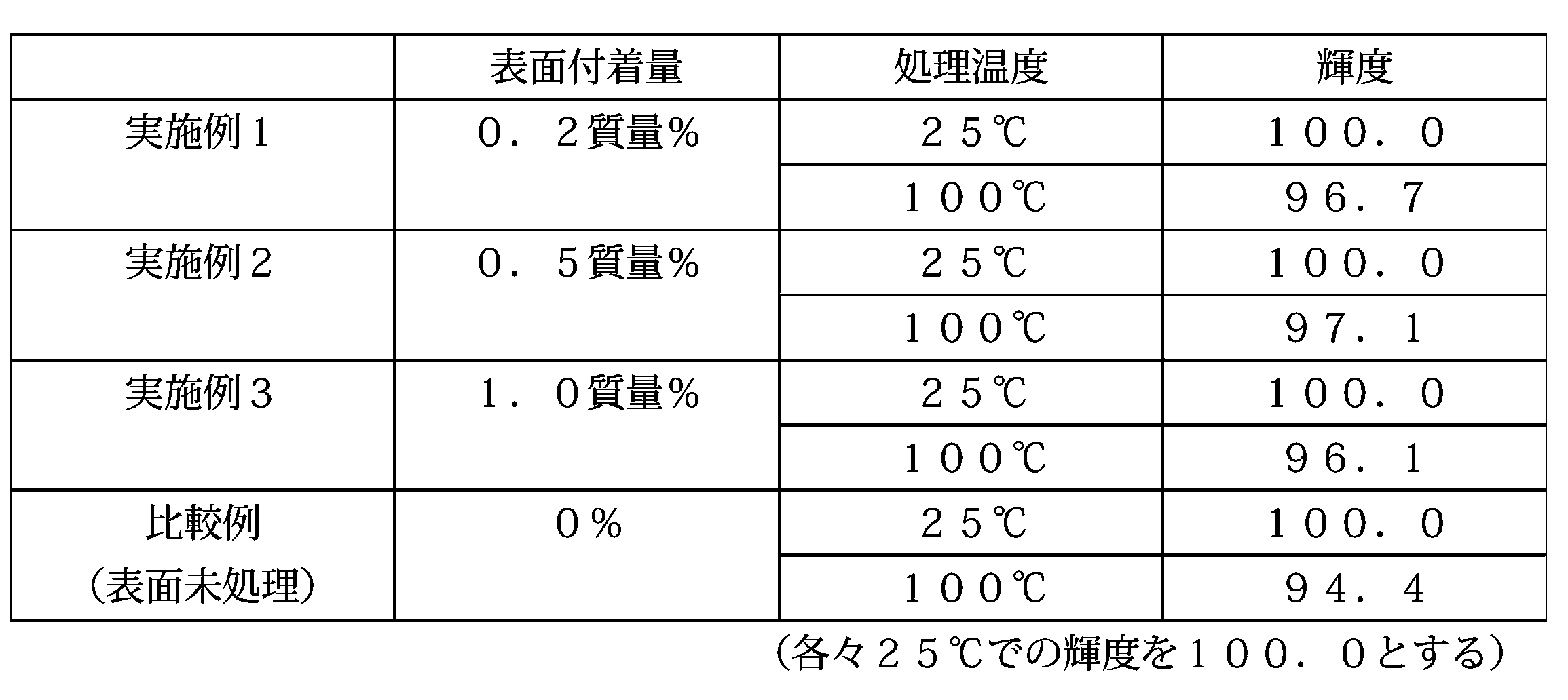
表2及び図1に示されるように、表面処理蛍光体粒子は、表面未処理の蛍光体粒子と比較して、室温から100℃へ温度が上昇した際の輝度の低下が明らかに少なかった。
(表面処理蛍光体粒子の観察)
図2は、実施例2で得られた表面処理蛍光体粒子(表面付着量0.5質量%)の電子顕微鏡写真である。図2からも、蛍光体粒子の表面にリン酸ランタンが付着していることが確認された。
図2は、実施例2で得られた表面処理蛍光体粒子(表面付着量0.5質量%)の電子顕微鏡写真である。図2からも、蛍光体粒子の表面にリン酸ランタンが付着していることが確認された。
本発明の表面処理蛍光体粒子の製造方法によれば、共沈反応によりリン酸ランタンが生成し、蛍光体粒子表面に付着することによって、焼成処理を行わずに表面処理蛍光体粒子を製造することができる。そのため、蛍光体粒子の初期の輝度を十分に高いレベルに維持することができる。さらに、本表面処理蛍光体粒子によれば、蛍光体粒子を備える各種デバイスを製造する段階で受ける熱履歴による輝度の低下も十分に抑制される。
Claims (10)
- ランタンを含有する水溶液とリン酸を含有する水溶液とを、蛍光体粒子の存在下で混合して得られる分散液中で、当該蛍光体粒子及びその表面に付着したリン酸ランタンを有する表面処理蛍光体粒子を形成させる工程を備える、表面処理蛍光体粒子の製造方法。
- 前記蛍光体粒子が(Ba1-x-zSrxEuz)MgAl10O17(xは0≦x≦0.5、zは0.01≦z≦0.2を満たす。)で表される蛍光体を含む、請求項1に記載の製造方法。
- 前記蛍光体粒子が(Ca1-y-zSryEuz)MgSi2O6(yは0≦y≦1、zは0.001≦z≦0.1を満たし、y+z≦1である。)で表される蛍光体を含む、請求項1に記載の製造方法。
- 前記蛍光体粒子が(Zn2-wMnw)SiO4(wは0.001≦w≦0.1を満たす。)で表される蛍光体を含む、請求項1に記載の製造方法。
- 当該表面処理蛍光体粒子が200℃以上に加熱されない方法により当該表面処理蛍光体粒子を前記分散液中から回収する工程を更に備える、請求項1~4のいずれか一項に記載の製造方法。
- 蛍光体粒子と、
ランタンを含有する水溶液とリン酸を含有する水溶液とを当該蛍光体粒子の存在下で混合する方法により、当該蛍光体粒子の表面に付着させたリン酸ランタンと、
を備える、表面処理蛍光体粒子。 - 前記蛍光体粒子が(Ba1-x-zSrxEuz)MgAl10O17(xは0≦x≦0.5、zは0.01≦z≦0.2を満たす。)で表される蛍光体を含む、請求項6に記載の表面処理蛍光体粒子。
- 前記蛍光体粒子が(Ca1-y-zSryEuz)MgSi2O6(yは0≦y≦1、zは0.001≦z≦0.1を満たし、y+z≦1である。)で表される蛍光体を含む、請求項6に記載の表面処理蛍光体粒子。
- 前記蛍光体粒子が(Zn2-wMnw)SiO4(wは0.001≦w≦0.1を満たす。)で表される蛍光体を含む、請求項6に記載の表面処理蛍光体粒子。
- 前記蛍光体粒子の質量を基準とした前記リン酸ランタンの質量比が0.01~5質量%である、請求項6~9のいずれか一項に記載の表面処理蛍光体粒子。
Applications Claiming Priority (2)
| Application Number | Priority Date | Filing Date | Title |
|---|---|---|---|
| JP2009-129305 | 2009-05-28 | ||
| JP2009129305A JP2010275426A (ja) | 2009-05-28 | 2009-05-28 | 表面処理蛍光体粒子の製造方法及び表面処理蛍光体粒子 |
Publications (1)
| Publication Number | Publication Date |
|---|---|
| WO2010137533A1 true WO2010137533A1 (ja) | 2010-12-02 |
Family
ID=43222643
Family Applications (1)
| Application Number | Title | Priority Date | Filing Date |
|---|---|---|---|
| PCT/JP2010/058663 Ceased WO2010137533A1 (ja) | 2009-05-28 | 2010-05-21 | 表面処理蛍光体粒子の製造方法及び表面処理蛍光体粒子 |
Country Status (3)
| Country | Link |
|---|---|
| JP (1) | JP2010275426A (ja) |
| TW (1) | TW201109422A (ja) |
| WO (1) | WO2010137533A1 (ja) |
Families Citing this family (5)
| Publication number | Priority date | Publication date | Assignee | Title |
|---|---|---|---|---|
| US20150137037A1 (en) * | 2012-06-08 | 2015-05-21 | Denki Kagaku Kogyo Kabushiki Kaisha | Method for treating surface of phosphor, phosphor, light-emitting device, and illumination device |
| US10153405B2 (en) | 2016-02-26 | 2018-12-11 | Nichia Corporation | Fluorescent material, light emitting device, and method for producing fluorescent material |
| US9879179B2 (en) | 2016-03-30 | 2018-01-30 | Nichia Corporation | Fluorescent material, light-emitting device, and method for producing fluorescent material |
| JP6485467B2 (ja) * | 2016-03-30 | 2019-03-20 | 日亜化学工業株式会社 | 蛍光体、発光装置及び蛍光体の製造方法 |
| JP7795084B2 (ja) * | 2022-01-27 | 2026-01-07 | 日亜化学工業株式会社 | 蛍光体及びその製造方法 |
Citations (7)
| Publication number | Priority date | Publication date | Assignee | Title |
|---|---|---|---|---|
| JP2004182907A (ja) * | 2002-12-04 | 2004-07-02 | Matsushita Electric Ind Co Ltd | 赤色蛍光体およびこれを用いた蛍光ランプ |
| JP2005303289A (ja) * | 2004-02-23 | 2005-10-27 | Lumileds Lighting Us Llc | 燐光体変換型発光デバイス |
| JP2006269938A (ja) * | 2005-03-25 | 2006-10-05 | Nichia Chem Ind Ltd | 発光装置、発光素子用蛍光体及びその製造方法 |
| JP2007281484A (ja) * | 2006-04-10 | 2007-10-25 | Samsung Electro Mech Co Ltd | 白色発光ダイオードおよびその製造方法 |
| WO2008012266A1 (fr) * | 2006-07-28 | 2008-01-31 | Rhodia Operations | Precurseurs de luminophores et luminophores coeur-coquille |
| JP2008523169A (ja) * | 2004-12-07 | 2008-07-03 | コーニンクレッカ フィリップス エレクトロニクス エヌ ヴィ | 放射線源とルミネッセンス材料を含む照明システム |
| JP2009068001A (ja) * | 2007-08-21 | 2009-04-02 | Nichia Corp | 蛍光体及びそれを用いた蛍光ランプ |
-
2009
- 2009-05-28 JP JP2009129305A patent/JP2010275426A/ja active Pending
-
2010
- 2010-05-21 WO PCT/JP2010/058663 patent/WO2010137533A1/ja not_active Ceased
- 2010-05-26 TW TW099116831A patent/TW201109422A/zh unknown
Patent Citations (7)
| Publication number | Priority date | Publication date | Assignee | Title |
|---|---|---|---|---|
| JP2004182907A (ja) * | 2002-12-04 | 2004-07-02 | Matsushita Electric Ind Co Ltd | 赤色蛍光体およびこれを用いた蛍光ランプ |
| JP2005303289A (ja) * | 2004-02-23 | 2005-10-27 | Lumileds Lighting Us Llc | 燐光体変換型発光デバイス |
| JP2008523169A (ja) * | 2004-12-07 | 2008-07-03 | コーニンクレッカ フィリップス エレクトロニクス エヌ ヴィ | 放射線源とルミネッセンス材料を含む照明システム |
| JP2006269938A (ja) * | 2005-03-25 | 2006-10-05 | Nichia Chem Ind Ltd | 発光装置、発光素子用蛍光体及びその製造方法 |
| JP2007281484A (ja) * | 2006-04-10 | 2007-10-25 | Samsung Electro Mech Co Ltd | 白色発光ダイオードおよびその製造方法 |
| WO2008012266A1 (fr) * | 2006-07-28 | 2008-01-31 | Rhodia Operations | Precurseurs de luminophores et luminophores coeur-coquille |
| JP2009068001A (ja) * | 2007-08-21 | 2009-04-02 | Nichia Corp | 蛍光体及びそれを用いた蛍光ランプ |
Also Published As
| Publication number | Publication date |
|---|---|
| TW201109422A (en) | 2011-03-16 |
| JP2010275426A (ja) | 2010-12-09 |
Similar Documents
| Publication | Publication Date | Title |
|---|---|---|
| JP5224439B2 (ja) | 蛍光体、およびそれを用いた発光器具 | |
| CN101967376B (zh) | 发光物质 | |
| JP5234781B2 (ja) | 蛍光体とその製造方法および発光器具 | |
| KR101209488B1 (ko) | 효율적인, 녹색 발광 인광체 및 적색 발광 인광체와의 조합 | |
| JP5294245B2 (ja) | 蛍光体とその製造方法および発光器具 | |
| EP0921172A1 (en) | Method for producing a divalent europium-activated phosphor | |
| JP5578739B2 (ja) | アルカリ土類金属シリケート蛍光体及びその製造方法 | |
| KR20070041703A (ko) | 형광체를 이용한 조명기구 및 화상표시장치 | |
| CN1942553B (zh) | 白色发光二极管 | |
| JP5706441B2 (ja) | 放射線負荷に対する安定性及び大気湿度に対する耐性が改善されたストロンチウムオキシオルトシリケート蛍光体 | |
| JP2023522185A (ja) | 緑色発光蛍光体およびそのデバイス | |
| US6187225B1 (en) | Blue phosphor for plasma display and lamp application and method of making | |
| WO2010137533A1 (ja) | 表面処理蛍光体粒子の製造方法及び表面処理蛍光体粒子 | |
| WO2000001784A9 (en) | Small particle blue emitting lanthanum phosphate based phosphors for display and lamp applications and method of making | |
| JP5187817B2 (ja) | 蛍光体と発光器具 | |
| JP2015078317A (ja) | 蛍光体、その製造方法、発光装置、画像表示装置、顔料、および、紫外線吸収剤 | |
| CN101400758B (zh) | 铝酸盐系荧光体的制备方法和铝酸盐系荧光体 | |
| JP2006165266A (ja) | 発光装置 | |
| JP6729393B2 (ja) | 蛍光体及び発光装置並びに蛍光体の製造方法 | |
| JP2001234165A (ja) | 真空紫外線励起型蛍光体 | |
| JPH10298548A (ja) | 真空紫外線励起発光蛍光体およびその製造方法 | |
| WO2007066732A1 (ja) | 蛍光体とその製造方法および発光器具 | |
| RU2236432C2 (ru) | Красноизлучающий фотолюминофор для экранов плазменных панелей и способ его получения | |
| JP3754701B2 (ja) | 蛍光体及びそれを使用した発光素子 | |
| JP5014814B2 (ja) | 真空紫外線励起蛍光体 |
Legal Events
| Date | Code | Title | Description |
|---|---|---|---|
| 121 | Ep: the epo has been informed by wipo that ep was designated in this application |
Ref document number: 10780488 Country of ref document: EP Kind code of ref document: A1 |
|
| NENP | Non-entry into the national phase |
Ref country code: DE |
|
| 122 | Ep: pct application non-entry in european phase |
Ref document number: 10780488 Country of ref document: EP Kind code of ref document: A1 |