WO2010137515A1 - 画像表示装置および方法 - Google Patents
画像表示装置および方法 Download PDFInfo
- Publication number
- WO2010137515A1 WO2010137515A1 PCT/JP2010/058539 JP2010058539W WO2010137515A1 WO 2010137515 A1 WO2010137515 A1 WO 2010137515A1 JP 2010058539 W JP2010058539 W JP 2010058539W WO 2010137515 A1 WO2010137515 A1 WO 2010137515A1
- Authority
- WO
- WIPO (PCT)
- Prior art keywords
- image
- display
- field image
- field
- color
- Prior art date
- Legal status (The legal status is an assumption and is not a legal conclusion. Google has not performed a legal analysis and makes no representation as to the accuracy of the status listed.)
- Ceased
Links
Images











Classifications
-
- G—PHYSICS
- G09—EDUCATION; CRYPTOGRAPHY; DISPLAY; ADVERTISING; SEALS
- G09G—ARRANGEMENTS OR CIRCUITS FOR CONTROL OF INDICATING DEVICES USING STATIC MEANS TO PRESENT VARIABLE INFORMATION
- G09G3/00—Control arrangements or circuits, of interest only in connection with visual indicators other than cathode-ray tubes
- G09G3/20—Control arrangements or circuits, of interest only in connection with visual indicators other than cathode-ray tubes for presentation of an assembly of a number of characters, e.g. a page, by composing the assembly by combination of individual elements arranged in a matrix no fixed position being assigned to or needed to be assigned to the individual characters or partial characters
- G09G3/2007—Display of intermediate tones
-
- H—ELECTRICITY
- H04—ELECTRIC COMMUNICATION TECHNIQUE
- H04N—PICTORIAL COMMUNICATION, e.g. TELEVISION
- H04N21/00—Selective content distribution, e.g. interactive television or video on demand [VOD]
- H04N21/40—Client devices specifically adapted for the reception of or interaction with content, e.g. set-top-box [STB]; Operations thereof
- H04N21/43—Processing of content or additional data, e.g. demultiplexing additional data from a digital video stream; Elementary client operations, e.g. monitoring of home network or synchronising decoder's clock; Client middleware
- H04N21/431—Generation of visual interfaces for content selection or interaction; Content or additional data rendering
- H04N21/4318—Generation of visual interfaces for content selection or interaction; Content or additional data rendering by altering the content in the rendering process, e.g. blanking, blurring or masking an image region
-
- H—ELECTRICITY
- H04—ELECTRIC COMMUNICATION TECHNIQUE
- H04N—PICTORIAL COMMUNICATION, e.g. TELEVISION
- H04N21/00—Selective content distribution, e.g. interactive television or video on demand [VOD]
- H04N21/40—Client devices specifically adapted for the reception of or interaction with content, e.g. set-top-box [STB]; Operations thereof
- H04N21/43—Processing of content or additional data, e.g. demultiplexing additional data from a digital video stream; Elementary client operations, e.g. monitoring of home network or synchronising decoder's clock; Client middleware
- H04N21/442—Monitoring of processes or resources, e.g. detecting the failure of a recording device, monitoring the downstream bandwidth, the number of times a movie has been viewed, the storage space available from the internal hard disk
- H04N21/44213—Monitoring of end-user related data
- H04N21/44218—Detecting physical presence or behaviour of the user, e.g. using sensors to detect if the user is leaving the room or changes his face expression during a TV programme
-
- H—ELECTRICITY
- H04—ELECTRIC COMMUNICATION TECHNIQUE
- H04N—PICTORIAL COMMUNICATION, e.g. TELEVISION
- H04N5/00—Details of television systems
- H04N5/14—Picture signal circuitry for video frequency region
- H04N5/144—Movement detection
-
- H—ELECTRICITY
- H04—ELECTRIC COMMUNICATION TECHNIQUE
- H04N—PICTORIAL COMMUNICATION, e.g. TELEVISION
- H04N5/00—Details of television systems
- H04N5/44—Receiver circuitry for the reception of television signals according to analogue transmission standards
- H04N5/57—Control of contrast or brightness
-
- H—ELECTRICITY
- H04—ELECTRIC COMMUNICATION TECHNIQUE
- H04N—PICTORIAL COMMUNICATION, e.g. TELEVISION
- H04N9/00—Details of colour television systems
- H04N9/12—Picture reproducers
- H04N9/31—Projection devices for colour picture display, e.g. using electronic spatial light modulators [ESLM]
- H04N9/3102—Projection devices for colour picture display, e.g. using electronic spatial light modulators [ESLM] using two-dimensional electronic spatial light modulators
- H04N9/3111—Projection devices for colour picture display, e.g. using electronic spatial light modulators [ESLM] using two-dimensional electronic spatial light modulators for displaying the colours sequentially, e.g. by using sequentially activated light sources
-
- H—ELECTRICITY
- H04—ELECTRIC COMMUNICATION TECHNIQUE
- H04N—PICTORIAL COMMUNICATION, e.g. TELEVISION
- H04N9/00—Details of colour television systems
- H04N9/12—Picture reproducers
- H04N9/31—Projection devices for colour picture display, e.g. using electronic spatial light modulators [ESLM]
- H04N9/3179—Video signal processing therefor
-
- H—ELECTRICITY
- H04—ELECTRIC COMMUNICATION TECHNIQUE
- H04N—PICTORIAL COMMUNICATION, e.g. TELEVISION
- H04N9/00—Details of colour television systems
- H04N9/64—Circuits for processing colour signals
- H04N9/646—Circuits for processing colour signals for image enhancement, e.g. vertical detail restoration, cross-colour elimination, contour correction, chrominance trapping filters
-
- G—PHYSICS
- G09—EDUCATION; CRYPTOGRAPHY; DISPLAY; ADVERTISING; SEALS
- G09G—ARRANGEMENTS OR CIRCUITS FOR CONTROL OF INDICATING DEVICES USING STATIC MEANS TO PRESENT VARIABLE INFORMATION
- G09G2310/00—Command of the display device
- G09G2310/02—Addressing, scanning or driving the display screen or processing steps related thereto
- G09G2310/0235—Field-sequential colour display
-
- G—PHYSICS
- G09—EDUCATION; CRYPTOGRAPHY; DISPLAY; ADVERTISING; SEALS
- G09G—ARRANGEMENTS OR CIRCUITS FOR CONTROL OF INDICATING DEVICES USING STATIC MEANS TO PRESENT VARIABLE INFORMATION
- G09G2320/00—Control of display operating conditions
- G09G2320/02—Improving the quality of display appearance
- G09G2320/0242—Compensation of deficiencies in the appearance of colours
-
- G—PHYSICS
- G09—EDUCATION; CRYPTOGRAPHY; DISPLAY; ADVERTISING; SEALS
- G09G—ARRANGEMENTS OR CIRCUITS FOR CONTROL OF INDICATING DEVICES USING STATIC MEANS TO PRESENT VARIABLE INFORMATION
- G09G2320/00—Control of display operating conditions
- G09G2320/02—Improving the quality of display appearance
- G09G2320/0261—Improving the quality of display appearance in the context of movement of objects on the screen or movement of the observer relative to the screen
Definitions
- the present invention relates to an image display apparatus and method for performing color image display by a field sequential method.
- the first method is additive color mixing based on the space color mixing principle. More specifically, the individual sub-pixels of the three primary colors of light of R (red), G (green) and B (blue) are finely arranged in a plane, and each color light is discriminated using the spatial resolution of the human eye Disable and mix colors in the same screen to obtain a color image.
- Most of the first system such as the cathode ray tube system, the PDP (plasma display) system, and the liquid crystal system, which are currently on the market, correspond.
- a display device of a type that modulates light from a light source (backlight) to display an image using this first method for example, an element represented by a liquid crystal element, which does not emit light itself is used as a modulation element
- the following problems occur. That is, in the same screen, three drive circuits for driving the sub-pixels are required to correspond to the respective RGB colors. In addition, RGB color filters are required. Furthermore, since the color filter is present, the light utilization factor is reduced to 1/3 by the light from the light source being absorbed by the color filter.
- the second method is additive color mixing by time mixing. More specifically, the three primary colors of RGB light are divided along the time axis, and planar images of the respective primary colors are sequentially displayed as time passes (time-sequentially). Then, by switching the respective screens at an unrecognizable speed using the time resolution of the human eye, each color light can not be distinguished by time mixing due to the integration effect in the time direction of the eye, and a color image is obtained by time mixing. Is displayed.
- This method is generally called field sequential method.
- the second method is currently mainly used for the modulation method of a high-intensity high-heat light source such as a projector (projection display method) in which a decrease in light amount tends to cause a fatal heat loss. Also, the second method has been studied in various ways because it has the merit of high utilization efficiency of light.
- the second method has serious visual disadvantages.
- the basic principle of display is to switch each screen at a speed that can not be recognized using the time resolution of the human eye.
- the RGB images displayed sequentially in order of time do not mix well due to complex factors such as the restriction on the optic nerve of the eye and the sense of image recognition of the human brain.
- the image of each primary color is viewed as an afterimage, etc., and a significant discomfort is observed It causes a display phenomenon called color breaking which is given to a person.
- Patent Document 1 there is known a technique for reducing color breakup by providing a field in which white light component periods are mixed in each field of RGB field sequential (see, for example, Patent Document 1).
- Patent Document 2 there is a technique of extracting a white component and newly inserting a W field between RGBRGB... Sequentially to prevent color breakup by four sequential processes of RGB W RGB W. It is known (for example, refer patent document 2).
- Patent Document 3 There is also known a technique for preventing color breakup by extracting image information and changing the color origin coordinates of the primary color (basic color) itself to be processed.
- Patent Documents 4 to 7 various proposals for improving the display in the field sequential system have been proposed (see Patent Documents 4 to 7).
- Patent No. 3912999 gazette Patent No. 3878030 gazette JP 2008-310286 A Japanese Patent Application Publication No. 2007-264211 Japanese Patent Publication No. 2008-510347 Patent No. 3977675
- Patent Document 4 defines a case where a portion with high color purity of saturated color does not exist in an image as a mild image, and in that case, color mixing is achieved by lighting the entire white color component with backlight. It prevents cracking.
- the to-be-colored image parts with high saturation which are not mild images are scattered in the same image plane. For this reason, the presence of a portion having a high degree of saturation in the screen lowers the saturation by turning on the entire surface of the mixed color, so the partial color purity in the screen is not compatible with the removal of the color break.
- Patent Document 5 describes the luminance on the retina using various space-time diagrams and a retina diagram.
- color breakup is reduced by a configuration such as RGBKKK with K as a black screen.
- the diagram showing the luminance distribution on the retina described in Patent Document 5 is described as a trapezoid of a center symmetry despite the fact that the target image is decomposed into an integration of images having different luminances of RGB.
- the luminance component to be synthesized is a primary color image that is not a uniform black and white image, the luminance on the left and right of the eye-following reference on the retina is not actually in central symmetry as shown in the figure. . That is, the figure lacks strictness, and in fact, as shown in FIG.
- Patent Document 6 detects a moving part of a video signal for the purpose of correcting and correcting the displacement of the image on the retina caused by moving image tracking, and shifts the display video side from the beginning to the moving direction It is a plan to take measures by displaying. In this method, it is effective while following the part in question, but whether to follow or not is a subjectivity problem on the observer side. For this reason, the processing of adding a shift to the originally unshifted image is aggravated due to the fixed vision or simultaneous display of objects with different moving directions, etc., thereby further deteriorating the color breakup. It has a serious disadvantage of being perceived and can not be put to practical use.
- Patent Document 7 describes a scheme of distributing RGBYeMgCy at 6-fold speed.
- this proposal there is no concept of a luminance center for eye tracking, and it has been confirmed by the inventors of the present invention that, in fact, measures against color breakup have no effect as compared with the later-described display method proposed in the present application.
- the present invention has been made in view of such problems, and an object thereof is to provide an image display apparatus and method capable of suppressing the occurrence of color breakup in moving image tracking in the field sequential system. is there.
- An image display apparatus separates an input image into a plurality of color component images required for color display in frame units, and generates field images of a plurality of colors for display according to the field sequential method.
- the display order control unit that variably controls the display order in one frame period of field images of multiple colors in frame units, and the multiple colors by field sequential method
- a display unit for time-divisionally displaying the field images of the above when the display order control unit displays the moving image on the display unit, the retina is recognized by the field image group constituting one frame or the field image group constituting two temporally consecutive frames.
- the combined luminance distribution of the field image group above is maximum in the central part and the luminance decreases as going to the peripheral part, and the field image of multiple colors is spread so that the spread of the combined luminance distribution becomes symmetrical. It controls the display order of.
- the observer when the moving image is displayed on the display unit, the observer can receive the field image group constituting one frame or the field image group constituting two temporally consecutive frames.
- the composite luminance distribution of the field image group on the retina to be recognized becomes maximum in the central part and the luminance becomes lower as going to the peripheral part, and the spread of the composite luminance distribution becomes symmetrical.
- the display order of field images of multiple colors is controlled.
- the composite luminance distribution of the field image group on the retina recognized by the observer has the maximum luminance in the central portion. Since the display order of field images of multiple colors is controlled so that the luminance decreases as going to the periphery and the spread of the combined luminance distribution becomes symmetrical, the field of view of human vision It is possible to suppress the occurrence of color breakup in moving image tracking in the sequential method.
- FIG. 7 is an explanatory view showing the configuration of a subfield image in one frame period displayed by the image display device according to the first embodiment, with the vertical axis as a display signal level.
- FIG. 7 is an explanatory view showing the configuration of a subfield image in one frame period displayed by the image display device according to the first embodiment, with the vertical axis as a display luminance level. It is an explanatory view showing typically the display state of the picture by the image display device concerning a 1st embodiment.
- FIG. 6 is an explanatory view of a follow line of sight (following velocity line) in the case of following a moving object displayed on a display. It is explanatory drawing which shows the spatial frequency characteristic of the human eye with respect to chromaticity. It is explanatory drawing which shows the spatial frequency characteristic of the human eye with respect to the moving speed of a display object.
- FIG. 14 is an explanatory view showing the configuration of a subfield image in one frame period displayed by the image display device according to the second embodiment, with the vertical axis as a display signal level.
- FIG. 14 is an explanatory view showing the configuration of a subfield image in one frame period displayed by the image display device according to the second embodiment, with the vertical axis as a display luminance level.
- FIG. 21 is an explanatory view schematically showing a combined luminance distribution of two frame periods on the retina in the display state shown in FIG. 19; It is explanatory drawing which shows typically the display condition of the image by the image display apparatus which concerns on 5th Embodiment, (A) is the description which shows the state which partially thinned out the red component from the display condition shown in FIG. FIG. 21 (B) is an explanatory view showing a state in which the red color component is partially thinned out from the display state shown in FIG. 19 and the display interval is further reduced. It is an explanatory view showing typically the display state of the picture by the image display device concerning a 6th embodiment.
- FIG. 22 is explanatory drawing which shows typically the luminance distribution on the retina by the 1st flame
- FIG. 22 (B) is an explanatory view schematically showing a luminance distribution on the retina by the second frame in the display state shown in FIG. (C) is explanatory drawing which shows typically the luminance distribution of the synthesis
- (A) is explanatory drawing which shows typically the luminance distribution on the retina by the 1st flame
- FIG. 24 (B) is an explanatory view schematically showing a luminance distribution on the retina by the second frame in the display state shown in FIG. 24.
- (C) is explanatory drawing which shows typically the luminance distribution of the synthesis
- the display state when a moving object is displayed by dividing an image of one frame into three color field images in order of R, G, B by the conventional field sequential method is schematically shown together with the luminance distribution on the retina FIG. It is explanatory drawing about the color break which arises by the conventional field sequential system. It is explanatory drawing which showed the luminance distribution on the retina in the display state shown in FIG. 28 more correctly.
- FIG. 1 shows a configuration example of an image display device according to a first embodiment of the present invention.
- the image display apparatus includes a display control unit 1 to which a video signal including R, G and B color image signals representing an input image is input.
- a display panel 2 and a backlight 3 which are controlled by the display control unit 1 and perform color image display by the field sequential method are also provided.
- the display panel 2 performs image display in synchronization with the emission of each color light of the backlight 3.
- the display panel 2 is configured to time-divisionally display a plurality of field images by the field sequential method in accordance with the display order based on the control of the display control unit 1.
- the display panel 2 is made of, for example, a transmissive liquid crystal panel that displays an image by controlling passage of light emitted from the backlight 3 with liquid crystal molecules.
- a plurality of display pixels are regularly arranged two-dimensionally.
- the backlight 3 is a light source unit capable of emitting a plurality of types of color light necessary for color image display in a time division manner for each color light. Under the control of the display control unit 1, the backlight 3 is driven to emit light in accordance with the input video signal.
- the backlight 3 is disposed, for example, on the back side of the display panel 2 so as to illuminate the display panel 2.
- the backlight 3 can be configured using, for example, a light emitting diode (LED) as a light emitting element (light source).
- the backlight 3 is configured to be able to emit light of a plurality of colors independently by planarly arranging a plurality of LEDs in a two-dimensional manner, for example.
- the light emitting element is not limited to the LED.
- the backlight 3 is constituted of, for example, at least a combination of a red LED emitting red light, a green LED emitting green light, and a blue LED emitting blue light. Then, under the control of the display control unit 1, the LEDs of each color emit light (lit) independently to emit primary colors, and achromatic color (black and white) emission and complementary colors are emitted by additive color mixture of each color light.
- the achromatic color means black, gray, and white having only lightness among hue, lightness, and saturation which are three attributes of color.
- the backlight 3 can emit, for example, yellow which is one of complementary colors by turning off the blue LED and emitting red and green LEDs.
- light emission can be performed in any color other than the complementary color or the white color by adjusting the amount of light emission of each color LED and simultaneously emitting light with an appropriate color balance.
- the display control unit 1 generates a field image of a plurality of colors for display according to the field sequential method using a color image included in the video signal as an input image, and variably controls the display order of the field images of the plurality of colors It is possible to
- the display control unit 1 includes an image processing unit 11, a display order control unit 12, an output signal selection switcher 18, and a backlight color light selection switcher 19.
- the display panel 2 and the backlight 3 correspond to one specific example of the “display unit” in the present invention.
- the image processing unit 11 and the output signal selection switcher 18 correspond to a specific example of the “signal processing unit” in the present invention.
- the display order control unit 12 corresponds to one specific example of the “display order control unit” in the present invention.
- the image processing unit 11 divides an input image into a plurality of color component images required for color display in frame units, and generates field images of a plurality of colors for display according to the field sequential method. Specifically, the input image is decomposed into a plurality of color component images into primary color images of red component, green component and blue component, and field images of a plurality of colors are divided into red field image, green field image and blue field image. It is designed to generate field images.
- the output signal selection switcher 18 selectively outputs the field images of a plurality of colors generated by the image processing unit 11 to the display panel 2 under the control of the display order control unit 12.
- the backlight color light selection switcher 19 is configured to control the light emission color and the light emission timing of the backlight 3 under the control of the display order control unit 12.
- the backlight color light selection switcher 19 controls the light emission of the backlight 3 in synchronization with the timing of the field image to be displayed and appropriately emits the color light required for the field image to be displayed.
- the display order control unit 12 can change the display order of field images of a plurality of colors generated by the image processing unit 11 within one frame period on a frame basis via the output signal selection switcher 18 and the backlight color light selection switcher 19. It is to control.
- the display order control unit 12 controls the output order of field images of a plurality of colors displayed on the display panel 2 through the output signal selection switcher 18.
- the display order control unit 12 also controls the light emission order of the light emission color of the backlight 3 through the backlight color light selection switcher 19.
- the display order control unit 12 determines that the synthetic luminance distribution of the field image group on the retina, which is recognized by the observer by the field image group constituting one frame, has a predetermined distribution.
- the display order of field images of a plurality of colors is controlled to be a shape.
- the predetermined distribution shape is in consideration of human visual characteristics described later, and the luminance is maximized at the central portion and becomes lower as it goes to the peripheral portion, and the spread of the synthetic luminance distribution is symmetrical. It has a shape that
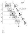
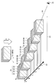
- FIG. 27 shows the concept of image display in the field sequential method.
- an image of one frame is divided into a plurality of color component image (field image) groups.
- FIG. 27 is a space-time diagram showing how an image of one frame group moves spatially to the right with the passage of time.
- each frame image is displayed in the order of frames A, B, C, D.
- Each frame image is divided into four color sub-fields.
- the A frame is divided into color subfields A1, A2. It is configured as a group of frame units as divided into A3 and A4.
- An arrow 22 indicates the passage of time
- an arrow 23 indicates a space axis (image display position coordinate axis).
- Arrow 24 indicates the center of observation (observation reference) by observer 25.
- the spatial notation by this three-dimensional illustration is not general, and the display as a plan view like FIG. 28 of a viewpoint which looks like a bird's-eye view from the direction of upper arrow H is general.
- description will be made using the display type of FIG.
- FIG. 28 shows a state in which a frame unit image divided into three fields of R, G and B by the field sequential method moves in the right direction (upper part of the figure). Each field image is displayed in the display order of R, G, and B within one frame period.
- the follow vision reference axis (following gaze) 20 is assumed to be at the center position of the G field image displayed at the center in one frame period.
- FIG. 28 also shows an overlapping image (brightness distribution on the retina) in tracking viewing on the retina (lower part of the figure).
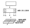
- color shifts called apparent color break occur before and after the moving direction. That is, when the original image is white in the field configuration as shown in FIG. 28 and the original image is moved to the right, as shown in FIG. .
- the luminance distribution on the retina shown in the lower part of FIG. 28 is incorrect. Therefore, the luminance distribution on the retina is more accurately shown in FIG.
- the "retinal stimulation level" is used as the unit of the vertical axis, this retinal stimulation level may be approximately close to the luminance after visual sensitivity processing.
- there are various conversion formulas according to various standards but in the present embodiment, simple ones are used to make the explanation easy to understand. This is a luminance conversion equation in which standard visual sensitivity characteristics are added to each of R, G, and B primary color signals.
- Display method in the present embodiment The display method according to the present embodiment will be described based on the above-described display method according to the prior art. Considering human visual characteristics, when moving images are displayed, if the luminance energy becomes high in the middle in time within one frame period and the luminance distribution becomes a predetermined shape that is temporally symmetrical, color is displayed. It is believed that cracking can be suppressed. The present embodiment realizes such a display method.
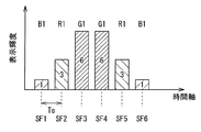
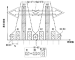
- FIG. 2 shows the configuration of the subfield image in one frame period displayed in the present embodiment, with the vertical axis as the display signal level.
- the black level signal level is 0, and the white level signal level is 255.
- Ts indicates the display interval of subfields.
- one frame is divided into six subfields SF1 to SF6, and six subfield images are displayed.
- the display order control unit 12 performs control such that the green color field image G1 is displayed continuously for two fields at a temporally central position within one frame period.
- the display order control unit 12 also causes the red field image R1 and the blue field image B1 to be red and blue, respectively, as viewed from the temporal center position, before and after the green field image G1 of two fields in time.
- the display sequence of the field image of each color is controlled so as to be displayed in order. That is, control is performed so as to be displayed in the order of B, R, G, G, R, and B.
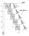
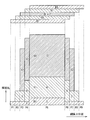
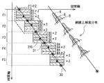
- FIG. 4 schematically shows the display state of the moving image in the present embodiment.
- FIG. 4 shows how a frame image composed of the field image group shown in FIGS. 2 and 3 moves in the right direction.
- the vertical axis is a time axis (sec)
- the horizontal axis is a space axis.
- the unit of the space axis is arbitrary, such as deg, mm, or pix (pixel unit).
- an image (brightness distribution on the retina) overlapping in tracking vision on the retina is simply illustrated for each frame.
- the follow line of sight 30 is represented by a line connecting the luminance gravity centers 31 of the respective frames.
- the luminance gravity center 31 is assumed to be at the center position of the green field image G1 displayed at the center in one frame period.
- FIG. 5 schematically shows the luminance distribution on the retina in one frame period in the display state shown in FIG. 4 for each color component.
- FIG. 6 further schematically shows the combined luminance distribution of each color on the retina.
- P1 to P11 indicate regions on the retina.
- the ratio of the luminance of each color in each area is indicated by a numerical value.
- the ratio of each color in each area is indicated by the numerical value of the signal level.
- the synthetic luminance of the field image group on the retina is recognized by the observer by the field image group constituting one frame.
- the distribution is maximum at the central portion (region P6 in FIGS. 5 and 6).
- the luminance decreases as going to the peripheral portion, and the spread of the combined luminance distribution is symmetrical.
- FIGS. 5 and 6 an example is shown in which white is displayed, so colors are mainly determined by the red component and the blue component in the peripheral portion (near areas P1, 2 or P10, 11) on the retina. There is a gap.
- the color shift of the peripheral portion is hardly recognized.
- human visual characteristics it is easy to recognize the brightness of the brightness in the order of green, red and blue.
- the frequency resolution (spatial resolution) of the human eye is high in the order of green, red and blue. That is, there is a characteristic that it is easy to recognize a color shift for green, and it is relatively difficult to recognize a color shift for blue. According to such a visual characteristic, according to the present embodiment, it is possible to suppress the occurrence of color breakup in moving image tracking vision.
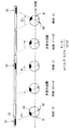
- FIG. 7 schematically shows the movement of the eyeball 61 in the case where the moving body 52 displayed on the display 51 is followed.
- FIG. 8 shows the follow line of sight (following velocity line) in the case where the moving object is viewed.
- the moving object 52 is intermittently displayed on the display 51 at time t0, t1 and t2 across the non-display interval t0 to t1 and t1 to t2.
- the light from the displayed moving body 52 forms an image on the retina 62 through the lens 63 of the eyeball 61.
- the image observer moves the eyeball 61 at a constant angular velocity ⁇ close to the moving speed to capture the display image while moving It is known to follow the body.
- the eyeball 61 moves in a predictive manner at a speed corresponding to the space-time at which the image appears and is displayed next even while the image disappears (non-display section). continue.
- the follow-up average velocity is temporarily assumed to be A (deg / sec).
- A deg / sec
- the exact mechanism of the action of the cerebrum's visual nervous system has not been clarified so that the velocity A is determined to be equal to ⁇ , the data obtained from previous experiments and experimental facts have not become clear. It is possible to guess.
- the color-based perception time it is known that there is a difference in the color-based perception speed depending on the approximate color order of R> G> B when the luminance is the same or the luminance is the same.
- FIG. 11 (A) shows the relationship between the presentation time of light stimulation and the apparent brightness.
- FIG. 11 (B) shows the sensory intensity change of the apparent brightness due to the difference in color.
- FIG. 11A there are visual characteristics in which the luminance is brighter and the display time can be felt brighter when the presentation time is short.
- FIG. 11B there is an order by color at the time when the brightness of the apparent light peaks. In this way, temporal sensitivities are in the order of red and green, but the visual sensitivity of luminance is 3 times for red and 6 for green, and there are double differences. Therefore, it is surmised that the green sensitivity is generally high when the field sequential image of the RGB three-color system is followed, and it greatly contributes to the configuration of the moving velocity line (following line of sight).
- the tracking average velocity A is not determined depending only on the visual characteristics, but also depends on the function of the visual nerve center in the brain.
- image information from the eye is visually processed by the brain.
- the eye movement muscle is controlled by the brain to follow the image.
- the brain makes the "more visible image” ⁇ " high-brightness, clear image "the approximate observation center. Make a judgment.
- the follow-up viewing speed is substantially servo-controlled by the brain at a speed at which a good image can be obtained. Therefore, it is considered that the observation center to be followed up is a portion serving as the luminance gravity center in the synthetic luminance distribution on the retina.
- the color with the high luminance level is approximately green. Therefore, the green field image G is considered as the luminance center of gravity of the combined field image group, and the average velocity line focusing on the moving velocity of this is taken as GV.
- the composite follow-up view in which the other colors overlap does not necessarily coincide with the GV, and as a whole, the high-brightness part becomes the follow-up view as a result of the image in which the colors are superimposed.
- the movement speed ⁇ of the viewpoint performed by the eyeball at this time is represented by a solid line as the follow line of sight 30 in the space-time view (FIG. 4) of the present embodiment.
- the inclination of the follow line of sight 30 represents the velocity ⁇ .
- the fields of the respective colors are displayed in such a display order that the spatial deviation of the composite image is minimized when substantially following the moving speed ⁇ of the luminance centroid 31 of the composite image of the field image group. Make up the image. As a result, it is possible to reduce color breakup as shown in FIGS. 29 and 30 which is perceived when displayed in the conventional RGB display system.
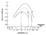
- FIG. 9 shows the spatial frequency characteristics of the human eye with respect to the chromaticity.
- FIG. 9 shows characteristics in the case of a sine wave pattern at the time of still image observation, which is not completely equivalent to Landolt's ring visual acuity, but as relative contrast sensitivity, in the order of green>red> blue, at an image frequency of 500 KHz or more , Indicates that there is a mutual difference of about 6 dB (times).
- red and blue have the meaning that the same luminance is obtained at about 200 KHz for blue, 1.3 MHz for red, and 2.6 MHz for green if the peaks that feel the same contrast are the same.
- Knowledge is used in band compression techniques for color signals such as NTSC television.
- FIG. 10 shows the spatial frequency characteristics of the human eye with respect to the movement speed of the display object.
- the moving speed at a peripheral position (12.degree. ECC) and a characteristic at a moving speed of 2 deg / sec and 0.25 deg / sec observed at the fovea on the retina (0.degree. ECC) The characteristic at the time of observing 20 deg / sec and 2 deg / sec is shown.
- FIG. 10 there is a decrease in visual acuity under the condition of displaying moving images in luminance stimulation. Journal of the Television Society Vol. 40, no. 1 (1986), pp. 46-53 or Vol. 40, no.
- the visual angular velocity which can follow the movement speed is It is said that 0 ⁇ ⁇ ⁇ 24 deg / s.
- the resolution decreases to 1/3 or less at a tracking speed of 20 deg / sec. From this, the allowable limit at the time of a still picture of the degree of deviation of each color of the synthetic image on the retina according to the display time position from the follow-up gaze depends on the moving speed.
- the follow-up line of sight 30 is determined depending on the luminance distribution on the retina obtained as a result of the space-time diagram (FIG. 4), and the spatial spread of the image is Become bigger or smaller.
- the shift allowance shown in FIG. 12 is a diagram in which the frequency resolution is regarded as a shift allowance. Blue is considered to be difficult to distinguish easily, even if there is a spatial spread of 7 times the red (14 times the green). Since the spatial resolution of red is equal to or less than half of that of green according to FIG. 9 at the time of still image observation, in FIG. 12, red is drawn to be twice as wide as green with respect to green. In practice, a high brightness image will tend to have a reduced shift allowance and a low brightness image will be mitigated. Taken together, the tolerance of the shift becomes a ratio that is slightly larger than the reciprocal of the luminance ratio, and according to the moving speed, the perception ability declines and the condition is further relaxed.
- the inter-frame image movement amount depends on the movement speed.
- Amount of shift (spread) amount of image movement between frames / number of fields in one frame (1)
- FIG. 13 shows the configuration of the subfield image in one frame period displayed in the present embodiment, with the vertical axis as the display signal level.
- the signal level of the black level is 0, the signal level of the white level is 255, and the display of a white image (image of the white level) is performed.
- FIG. 14 is an explanatory view showing the configuration of the subfield image of FIG. 13 with the vertical axis as the display luminance level.
- one frame is divided into five subfields SF1 to SF5, and five subfield images are displayed.
- the image processing unit 11 (FIG. 1) generates an image in which the signal level is doubled with respect to the signal level of the green component in the input image for the green field image.
- the display order control unit 12 performs control such that a green field image G1 whose signal level is doubled is displayed at a temporally central position within one frame period.
- the display order control unit 12 also displays the red field image R1 and the blue field image B1 in order of red and blue as viewed from the temporal center position respectively before and after the green field image G1.
- Control the display sequence of the field image of each color That is, control is performed so as to be displayed in the order of B, R, G (double luminance), R, and B.
- the luminance of the green field image is displayed twice, specifically, the light emission amount of the backlight 3 is controlled.
- FIG. 15 schematically shows the display state of the moving image in the present embodiment, similarly to the space-time diagram of FIG. 4.
- an image (brightness distribution on the retina) overlapping in tracking vision on the retina is simply illustrated for each frame.
- the follow line of sight 30 is represented by a line connecting the luminance gravity centers 31 of the respective frames.
- the luminance gravity center 31 is at the center position of the green field image G1 displayed at the center in one frame period.
- FIG. 16 schematically shows, for each color component, the luminance distribution on the retina in one frame period in the display state shown in FIG.
- the synthetic luminance distribution of the field image group on the retina which is recognized by the observer by the field image group constituting one frame, is The luminance is maximum at the central portion (region P5 in FIG. 16).
- the luminance decreases as going to the peripheral portion, and the spread of the combined luminance distribution is symmetrical. Therefore, also in the present embodiment, in consideration of the human visual characteristics, the color shift of the peripheral portion is hardly recognized, and the occurrence of the color breakup in the moving image tracking can be suppressed.
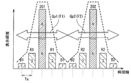
- FIG. 17 shows the display state of the two frame period displayed in the second embodiment, with the vertical axis as the display luminance level.
- FIG. 18 shows the display state of the two frame period displayed in the present embodiment, with the vertical axis as the display luminance level.
- Gp1 indicates the field image group according to the first frame F1
- Gp2 indicates the entire mass of the field image group according to the second frame F2.
- field images blue field images
- FIG. 17 shows the display state of the two frame period displayed in the second embodiment, with the vertical axis as the display luminance level.
- Gp1 indicates the field image group according to the first frame F1
- Gp2 indicates the entire mass of the field image group according to the second frame F2.
- field images blue field images
- the image processing unit 11 (FIG. 1) generates an image in which the signal level is doubled with respect to the signal level of the green component in the input image for the green field image. Also, a first combined blue field image is generated by combining two blue field images (B0 + B1) between the immediately preceding frame F0 and the current frame F1. Furthermore, a second composite blue field image is generated by combining the two blue field images (B1 + B2) between the current frame F1 and the temporally subsequent frame F2.
- the display order control unit 12 performs display control such that the first composite blue field image is shared and displayed at the same time between the immediately preceding frame F0 and the current frame F1. In addition, display control is performed such that the second composite blue field image is displayed in common at the same time between the current frame and the one frame later in time.
- the display order control unit 12 causes the green field image G1 whose signal level is doubled to be displayed at the temporally central position between the first combined blue field image and the second combined blue field image. Make it And, between the first composite blue field image and the green field image G1, and between the green field image G1 and the second composite blue field image, a red field image R1 is displayed, respectively. Control the display sequence of field images.
- the first composite blue field image (B0 + B1) to the second composite blue field image (B1 + B2) are considered as a field image group constituting one frame, the field on the retina
- the composite luminance distribution of the image group has the maximum luminance at the center.
- the luminance decreases as going to the peripheral portion, and the spread of the combined luminance distribution becomes symmetrical. Therefore, also in the present embodiment, in consideration of the human visual characteristics, the color shift of the peripheral portion is hardly recognized, and the occurrence of the color breakup in the moving image tracking can be suppressed.
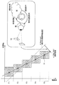
- FIG. 19 schematically shows the display state of the moving image in the present embodiment, similarly to the space-time diagram of FIG. 4.
- FIG. 19 simply shows an image (brightness distribution on the retina) overlapping for follow-up on the retina for each frame
- the retina on the display state shown in FIG. 19 is further shown in FIG.
- the synthetic luminance distribution of the field image group on the retina which is recognized by the observer by the field image group constituting one frame, is predetermined.
- the display order of field images of a plurality of colors was controlled so as to have a distribution shape.
- the retina is recognized by the display order control unit 12 not by the field image group constituting one frame but by the field image group constituting two temporally consecutive frames.
- the display order of the field images of a plurality of colors is controlled so that the composite luminance distribution above has a predetermined distribution shape.
- the display order control unit 12 controls the display order of the field images of a plurality of colors in the first frame F1 and the second frame F2 which are temporally continuous to be different. Then, as shown in FIG. 20, the synthetic luminance distribution of the field image group on the retina is recognized by the observer by the field image group for two frames, and the luminance becomes maximum at the central portion and goes to the peripheral portion. Make the brightness lower. And the display order of the field image of a plurality of colors is controlled so that the spread of the combined luminance distribution becomes symmetrical.
- the image processing unit 11 (FIG. 1) generates an image in which the signal level is doubled with respect to the signal level of the green component and the blue component in the input image for the green field image and the blue field image, respectively. Do. Within the display period of the first frame, the display order control unit 12 generates a blue field image B1 whose signal level is doubled, a red field image R1, a green field image G1 whose signal level is doubled, and a red color The display sequence of the field images of each color is controlled so as to be displayed in the order of the field images R1.
- the red field image R2, the green field image G2 in which the signal level is doubled, the red field image R2 and the blue field image B2 in which the signal level is doubled are displayed in this order Control the display sequence of the field image of each color.
- the display order of the colors of the field image group in the second frame F2 is reversed with respect to the first frame F1.
- the follow line of sight 30 is represented by a line connecting the luminance gravity centers 31 in a state where two frames are synthesized.
- the luminance gravity center 31 does not coincide with the center position 31G of the green field image.
- the composite luminance distribution of the field image group on the retina which is recognized by the observer by the field images of two frames, has the maximum luminance at the central portion.
- the luminance decreases as going to the peripheral portion, and the spread of the combined luminance distribution becomes symmetrical. Therefore, also in the present embodiment, in consideration of the human visual characteristics, the color shift of the peripheral portion is hardly recognized, and the occurrence of the color breakup in the moving image tracking can be suppressed.
- FIG. 21B schematically shows the display state of the moving image in the present embodiment, similarly to the space-time diagram of FIG. 4.
- FIG. 21A shows a state in which the red component is partially thinned out from the display state shown in FIG.
- display order control unit 12 partially thins out the red component from the display state shown in FIG. Display control is performed.
- the composite luminance distribution of the field image group on the retina which is recognized by the observer by the field images of two frames, has the maximum luminance at the central portion.
- the luminance decreases as going to the peripheral portion, and the spread of the combined luminance distribution becomes symmetrical. Therefore, also in the present embodiment, in consideration of the human visual characteristics, the color shift of the peripheral portion is hardly recognized, and the occurrence of the color breakup in the moving image tracking can be suppressed.
- FIG. 22 schematically shows the display state of the moving image in the present embodiment, similarly to the space-time diagram of FIG. Although an image (brightness distribution on the retina) overlapping in follow-up vision on the retina is simply illustrated in FIG. 22 for each frame, the display state shown in FIG. 7 schematically shows a combined luminance distribution of two frame periods on the retina in FIG.
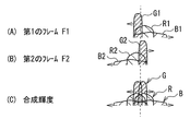
- FIG. 23A schematically shows the luminance distribution on the retina by the field image group of the first frame F1 in the display state shown in FIG.
- FIG. 23B schematically shows the luminance distribution on the retina by the field image group of the second frame F2 in the display state shown in FIG.
- FIG. 23C schematically shows a state in which the luminance distributions shown in FIGS. 23A and 23B are synthesized.
- the composite luminance distribution on the retina has a predetermined distribution shape in which the display order control unit 12 recognizes the observer by the field image group constituting two temporally consecutive frames. Control the display order of field images of multiple colors.
- the display order control unit 12 controls the display order of the field images of a plurality of colors in the first frame F1 and the second frame F2 which are temporally continuous to be different.
- the synthetic luminance distribution of the field image group on the retina is recognized by the observer by the field image group for two frames, and the luminance becomes maximum at the central portion and goes to the peripheral portion Make the brightness lower.
- the display order of the field image of a plurality of colors is controlled so that the spread of the combined luminance distribution becomes symmetrical.
- the image processing unit 11 (FIG. 1) generates three-color field images of a red field image, a green field image, and a blue field image as field images of a plurality of colors.
- the display order control unit 12 controls the display sequence of the field images of each color so that the blue field image B1, the red field image R1, and the green field image G1 are displayed in order in the display period of the first frame F1. .
- the display sequence of the field images of each color is controlled so that the green field image G2, the red field image R2 and the blue field image B2 are displayed in order.
- the display order of the colors of the field image group in the second frame F2 is reversed with respect to the first frame F1.
- the display order control unit 12 inserts the non-display section K for one field period between the display period of the first frame F1 and the display period of the second frame F2. Display control.
- FIG. 22 shows an example in which the non-display section K is placed at the beginning of the second frame F2, the non-display section K may be provided at the end of the first frame F1 instead. It is substantially the same.
- the follow-up line of sight 30 is represented by a line connecting the luminance gravity centers 31 in a state in which two frames are synthesized.
- the luminance gravity center 31 does not coincide with the center position 31G of the green field image or the center position 31R of the red field image.
- the composite luminance distribution of the field image group on the retina which is recognized by the observer by the field images of two frames, has the maximum luminance at the central portion.
- the luminance decreases as going to the peripheral portion, and the spread of the combined luminance distribution becomes symmetrical. Therefore, also in the present embodiment, in consideration of the human visual characteristics, the color shift of the peripheral portion is hardly recognized, and the occurrence of the color breakup in the moving image tracking can be suppressed.
- FIG. 24 schematically shows a display state of an image according to a comparative example to the sixth embodiment (FIG. 22).
- FIG. 24 an image (brightness distribution on the retina) overlapping for follow-up on the retina is simply illustrated for each frame, but the display state shown in FIG. 24 is further shown in FIG. 7 schematically shows a combined luminance distribution of two frame periods on the retina in FIG.
- FIG. 25A schematically shows the luminance distribution on the retina by the field image group of the first frame F1 in the display state shown in FIG.
- FIG. 25B schematically shows the luminance distribution on the retina by the field image group of the second frame F2 in the display state shown in FIG.
- FIG. 25C schematically shows a state in which the luminance distributions shown in FIGS. 25A and 25B are synthesized.
- the display order of field images of each color in each frame is the same as in the display method of FIG.
- the non-display section K is not provided between the adjacent frames.
- the synthetic luminance distribution of the field image group on the retina is recognized by the observer by the field image group for two frames, as shown in FIG. Is far from the predetermined distribution shape for not being recognized. That is, in the luminance distribution on the retina by the first frame F1 (FIG. 25 (A)) and the luminance distribution on the retina by the second frame F2 (FIG. 25 (B)) And are not separated sufficiently on the retina. For this reason, it looks like a double image spatially.
- FIG. 26 shows an example of the configuration of a display device that performs such backlight control.
- the backlight 33 is capable of independent light emission control for each partial light emission area 36 in accordance with an input video signal.
- the light source is configured by combining LEDs of each color of red LED 3R that emits red light, green LED 3G that emits green light, and blue LED 3B that emits blue light, and emits a plurality of color lights by additively mixing each color light It is supposed to At least one such light source is disposed in the partial light emitting area 36.
- the present invention is not limited to the above embodiments, and various modifications are possible.
- the case is shown in which field images of three primary colors of red, green and blue are generated as time-division display as field images of multiple colors, but colors different from these three primary colors are used Color display may be performed.
- pure three primary colors may be used to perform color display with other three colors having slightly different hues.
- field images of complementary colors of three colors such as yellow (Ye), cyan (Cy), and magenta (Mg) may be generated as field images of a plurality of colors and displayed in a time division manner.
- Ye is a composite color of R and G
- Cy is a composite color of G and B
- Mg is a composite color of R and B.
- the order of height of frequency resolution and width of band sensitivity by human eyes is in the order of Ye>Cy> Mg.
Landscapes
- Engineering & Computer Science (AREA)
- Multimedia (AREA)
- Signal Processing (AREA)
- Health & Medical Sciences (AREA)
- General Health & Medical Sciences (AREA)
- Social Psychology (AREA)
- Computer Networks & Wireless Communication (AREA)
- Databases & Information Systems (AREA)
- Physics & Mathematics (AREA)
- Computer Hardware Design (AREA)
- General Physics & Mathematics (AREA)
- Theoretical Computer Science (AREA)
- Control Of Indicators Other Than Cathode Ray Tubes (AREA)
- Liquid Crystal Display Device Control (AREA)
- Liquid Crystal (AREA)
- Video Image Reproduction Devices For Color Tv Systems (AREA)
Abstract
Description
[画像表示装置の全体構成]
図1は、本発明の第1の実施の形態に係る画像表示装置の構成例を示している。この画像表示装置は、入力画像を表すR,G,Bのカラー画像信号が含まれた映像信号が入力される表示制御部1を備えている。また、表示制御部1によって制御され、フィールドシーケンシャル方式によってカラー画像表示を行う表示パネル2およびバックライト3を備えている。
表示制御部1は、映像信号に含まれるカラー画像を入力画像として、フィールドシーケンシャル方式による表示用の複数色のフィールド画像を生成すると共に、それら複数色のフィールド画像の表示順序をフレーム単位で可変制御することが可能となっている。表示制御部1は、画像処理部11と、表示順序制御部12と、出力信号選択スイッチャ18と、バックライト色光選択スイッチャ19とを有している。
表示順序制御部12は、表示パネル2において移動画像を表示したときに、1フレームを構成するフィールド画像群によって観察者に認識される、網膜上でのフィールド画像群の合成輝度分布が所定の分布形状となるように複数色のフィールド画像の表示順序を制御する。所定の分布形状とは、後述する人間の視覚特性を考慮したものであり、中央部で輝度が最大となり周辺部に行くに連れて輝度が低くなり、かつ合成輝度分布の広がりが左右対称的となるような形状である。
この画像表示装置の動作(表示方法)について説明する前に、まず、従来技術との比較を行うために、従来技術によるフィールドシーケンシャル方式の表示手法およびその問題点について説明する。なお、以下の説明においては、特別な場合を除き、色覚特性と視聴環境は標準的なモデルを想定して説明する。標準的なモデルとして、観察者は正常色覚者であり、明所視の環境で画像を表示するものとする。
例えばSDTVでは、輝度成分Yは、
Y=0.299*R+0.587*G+0.114*B
で表される(*は乗算記号)。なお、厳密には各種規格による種々の変換式があるが、本実施の形態では説明を分かりやすくするため、平易なものを使用する。これは、R,G,Bの各原色信号に、標準的な視感度特性を加味した輝度変換式となっている。標準的な視感度特性を加味した場合、R,G,Bの各原色信号は輝度比率がおおよそ、
R:G:B=0.3:0.6:0.1となるように変換される。
このため、図28では、網膜上で全体的に平坦な輝度分布とされているが、視感度特性を考慮すると正確には図30に示したように、左右端部の輝度レベルの分布が異なっている。すなわち、図30に示したように、黄色成分Yeおよび赤色成分Rのずれが知覚される右側の部分32と、青色成分Bおよびシアン成分Cyのずれが知覚される左側の部分33とでは輝度分布が異なる。つまり、輝度のエネルギー分布が網膜合成画像上で不揃いになり、左右非対称で、いびつになる。
以上の従来技術による表示手法を踏まえて、本実施の形態における表示方法について説明する。人間の視覚特性を考慮すると、移動画像を表示したときに、1フレーム期間内で、時間的に中央で輝度エネルギーが高くなり、かつ時間的に対称的な所定形状の輝度分布になれば、色割れを抑制できると考えられる。本実施の形態は、そのような表示手法を実現したものである。
R:G:B=3:6:1で表される。
次に、人間の視覚特性についてより具体的に説明する。また、色ずれの認識との関係について説明する。
ω=(Δθ/Δt)
G=1として、R<2,B<14のような関係が成り立つ。
図12は、このような人間の視覚特性に基づいた空間的な色ずれの許容量を模式的に示している。
0≦ω≦24deg/s程度といわれている。一方で、図10に示したように、20deg/secの追従速度で、1/3以下の解像力に低下する特徴がある。このことから、追従視線からの表示時間位置による網膜上の合成イメージの各色の逸脱度合いの静止画時の許容量限度は、移動速度に依存する。本実施の形態の表示方法では、時空図(図4)の結果として求めた網膜上の輝度分布に依存して、追従視線30が決まると共に、移動速度に依存して、像の空間的広がりが大きくなったり小さくなったりする。広がりの範囲を静止画状態で限定すれば、動画時にはさらに悪くなり1/3の識別しかできないようになると考えられる。図12に示したずれ許容量は、周波数分解能をずれ許容量と見立てた図である。青は、赤に対して7倍のずれ(緑に対して14倍)の空間的広がりがあっても、容易に識別できにくいだろうことが考えられる。静止画観測時には図9より、赤の空間分解能が緑の半分以下であるので、図12では、緑に対して赤は2倍の空間的広がりが許容できるものとして描いている。実際には、輝度の高い画像は、ずれ許容量が減少し、輝度の低い画像は緩和される方向になる。総合すると、ずれの許容量は輝度比の逆数よりやや差の大きい比率になるとともに移動速度に応じて、知覚能力が衰えるのでさらに条件は緩和される。
ずれ(広がり)量=フレーム間画像移動量/1フレーム内フィールド枚数 …(1)
1. 図12に示したように、G=1として、R<2,B<14以下の帯域空間コントラスト視覚特性比(図9)を満たすずれにあること。
2. 動画時には移動速度に応じて、変化する帯域減衰の量以下に(1)式が収まっていること。
3. 追従視線を中心として、輝度分布の広がりが左右対称になっていること。
次に、本発明の第2の実施の形態に係る画像表示装置について説明する。なお、上記第1の実施の形態に係る画像表示装置と実質的に同一の構成部分には同一の符号を付し、適宜説明を省略する。
次に、本発明の第3の実施の形態に係る画像表示装置について説明する。なお、上記第1または第2の実施の形態に係る画像表示装置と実質的に同一の構成部分には同一の符号を付し、適宜説明を省略する。
次に、本発明の第4の実施の形態に係る画像表示装置について説明する。なお、上記第1ないし第3の実施の形態に係る画像表示装置と実質的に同一の構成部分には同一の符号を付し、適宜説明を省略する。
次に、本発明の第5の実施の形態に係る画像表示装置について説明する。なお、上記第1ないし第4の実施の形態に係る画像表示装置と実質的に同一の構成部分には同一の符号を付し、適宜説明を省略する。
次に、本発明の第6の実施の形態に係る画像表示装置について説明する。なお、上記第1ないし第5の実施の形態に係る画像表示装置と実質的に同一の構成部分には同一の符号を付し、適宜説明を省略する。
図24は、第6の実施の形態(図22)に対する比較例による画像の表示状態を模式的に示している。図24には、網膜上で追従視時に重なり合うイメージ(網膜上での輝度分布)を各フレームごとに簡易的に図示してあるが、図25(C)にさらに、図24に示した表示状態における網膜上での2フレーム期間の合成の輝度分布を模式的に示す。図25(A)は、図24に示した表示状態における第1のフレームF1のフィールド画像群による網膜上での輝度分布を模式的に示している。図25(B)は図24に示した表示状態における第2のフレームF2のフィールド画像群による網膜上での輝度分布を模式的に示している。図25(C)には、図25(A)と図25(B)とに示した輝度分布を合成した状態を模式的に示している。
次に、本発明の第7の実施の形態に係る画像表示装置について説明する。なお、上記第1ないし第6の実施の形態に係る画像表示装置と実質的に同一の構成部分には同一の符号を付し、適宜説明を省略する。
本発明は、上記各実施の形態に限定されず種々の変形実施が可能である。
以上の各実施の形態の説明では、複数色のフィールド画像として、赤色、緑色および青色の3原色のフィールド画像を生成して時分割表示する場合を例にしたが、これら3原色とは異なる色でカラー表示を行うものであっても良い。例えば純粋な3原色とは色相がわずかに異なる他の3色でカラー表示を行うものであっても良い。
Ye(=R+G)>Cy(=G+B)>Mg(=R+B)の順である。また、人間の眼による周波数分解能の高さと帯域感度の広さの順も、Ye>Cy>Mgの順である。従って、これら補色3色のフィールド画像群による時分割表示では、位置ずれや空間的広がりの相対的な許容量は、Yeが最も小さくMgが最も大きくなり、Ye>Cy>Mgの順に色ずれを認識しやすいと考えられる。従って、上記各実施の形態における、RGBの各色を、G→Ye,R→Cy,B→Mgと置き換えるような組み合わせで表示すれば、同様の色割れ低減効果が得られる。例えば上記第1の実施の形態における「B,R,G,G,R,B」の表示順に代えて、1フレーム期間内で「Mg,Cy,Ye,Ye,Cy,Mg」の表示順で表示する方法であっても良い。
Claims (11)
- 入力画像をフレーム単位でカラー表示に必要とされる複数の色成分画像に分解し、フィールドシーケンシャル方式による表示用の複数色のフィールド画像を生成する信号処理部と、
前記複数色のフィールド画像の1フレーム期間内での表示順序をフレーム単位で可変制御する表示順序制御部と、
前記表示順序制御部の制御に基づく表示順序に従って、フィールドシーケンシャル方式により前記複数色のフィールド画像を時分割表示する表示部と
を備え、
前記表示順序制御部は、
前記表示部において移動画像を表示したときに、1フレームを構成するフィールド画像群または時間的に連続する2フレームを構成するフィールド画像群によって観察者に認識される、網膜上での前記フィールド画像群の合成輝度分布が中央部で輝度が最大となり周辺部に行くに連れて輝度が低くなり、かつ前記合成輝度分布の広がりが左右対称的となるように、前記複数色のフィールド画像の表示順序を制御する
ようになされている画像表示装置。 - 前記信号処理部は、前記複数の色成分画像として前記入力画像を赤色成分、緑色成分、および青色成分の原色画像に分解し、前記複数色のフィールド画像として赤色フィールド画像、緑色フィールド画像、および青色フィールド画像の3色のフィールド画像を生成する
ようになされている請求項1に記載の画像表示装置。 - 前記表示順序制御部は、
1フレーム期間内で時間的な中心位置に前記緑色フィールド画像が表示され、かつ前記緑色フィールド画像に対して時間的に前と後とにそれぞれ、前記赤色フィールド画像および前記青色フィールド画像が前記時間的な中心位置から見て赤色、青色の順に表示されるように、各色のフィールド画像の表示順次を制御する
ようになされている請求項2に記載の画像表示装置。 - 前記表示順序制御部は、
1フレーム期間内で時間的な中心位置に前記緑色フィールド画像が2フィールド分、時間的に連続して表示され、かつ前記2フィールドの緑色フィールド画像に対して時間的に前と後とにそれぞれ、前記赤色フィールド画像および前記青色フィールド画像が前記時間的な中心位置から見て赤色、青色の順に表示されるように、各色のフィールド画像の表示順次を制御する
ようになされている請求項3に記載の画像表示装置。 - 前記信号処理部は、前記緑色フィールド画像については、前記入力画像における緑色成分の信号レベルに対して信号レベルを2倍にした画像を生成するようになされ、
前記表示順序制御部は、
1フレーム期間内で時間的な中心位置に、前記信号レベルが2倍にされた緑色フィールド画像が表示され、かつ前記緑色フィールド画像に対して時間的に前と後とにそれぞれ、前記赤色フィールド画像および前記青色フィールド画像が前記時間的な中心位置から見て赤色、青色の順に表示されるように、各色のフィールド画像の表示順次を制御する
ようになされている請求項3に記載の画像表示装置。 - 前記信号処理部は、前記緑色フィールド画像については、前記入力画像における緑色成分の信号レベルに対して信号レベルを2倍にした画像を生成するようになされ、かつ、時間的に1つ前のフレームと現在のフレームとの間で2つの青色フィールド画像を合成した第1の合成青色フィールド画像を生成すると共に、現在のフレームと時間的に1つ後のフレームとの間で2つの青色フィールド画像を合成した第2の合成青色フィールド画像を生成するようになされ、
前記表示順序制御部は、
時間的に1つ前のフレームと現在のフレームとの間で前記第1の合成青色フィールド画像が同一の時間に共通化して表示され、現在のフレームと時間的に1つ後のフレームとの間で前記第2の合成青色フィールド画像が同一の時間に共通化して表示されるように制御すると共に、前記第1の合成青色フィールド画像と前記第2の合成青色フィールド画像との間の時間的な中心位置に、前記信号レベルが2倍にされた緑色フィールド画像が表示され、かつ、前記第1の合成青色フィールド画像と前記緑色フィールド画像との間、および前記緑色フィールド画像と前記第2の合成青色フィールド画像との間にそれぞれ、前記赤色フィールド画像が表示されるように、各色のフィールド画像の表示順次を制御する
ようになされている請求項2に記載の画像表示装置。 - 前記表示順序制御部は、
時間的に連続する第1のフレームと第2のフレームとにおける前記複数色のフィールド画像の表示順序を異ならせるように制御すると共に、前記第1のフレームと前記第2のフレームとを構成する2フレーム分のフィールド画像群によって観察者に認識される、網膜上での前記フィールド画像群の合成輝度分布が中央部で輝度が最大となり周辺部に行くに連れて輝度が低くなり、かつ前記合成輝度分布の広がりが左右対称的となるように、前記複数色のフィールド画像の表示順序を制御する
ようになされている請求項1または2に記載の画像表示装置。 - 前記信号処理部は、前記複数色のフィールド画像として赤色フィールド画像、緑色フィールド画像、および青色フィールド画像の3色のフィールド画像を生成するようになされ、かつ、前記緑色フィールド画像および前記青色フィールド画像についてそれぞれ、前記入力画像における緑色成分および青色成分の信号レベルに対して信号レベルを2倍にした画像を生成するようになされ、
前記表示順序制御部は、
前記第1のフレームの表示期間内では、信号レベルが2倍にされた青色フィールド画像、赤色フィールド画像、信号レベルが2倍にされた緑色フィールド画像、および赤色フィールド画像の順に表示され、
前記第2のフレームの表示期間内では、赤色フィールド画像、信号レベルが2倍にされた緑色フィールド画像、赤色フィールド画像、および信号レベルが2倍にされた青色フィールド画像の順に表示されるように、各色のフィールド画像の表示順次を制御する
ようになされている請求項7に記載の画像表示装置。 - 前記信号処理部は、前記複数色のフィールド画像として赤色フィールド画像、緑色フィールド画像、および青色フィールド画像の3色のフィールド画像を生成するようになされ、
前記表示順序制御部は、
前記第1のフレームの表示期間内では、青色フィールド画像、赤色フィールド画像、および緑色フィールド画像の順に表示され、
前記第2のフレームの表示期間内では、緑色フィールド画像、赤色フィールド画像、および青色フィールド画像の順に表示されるように、各色のフィールド画像の表示順次を制御すると共に、
前記第1のフレームの表示期間と前記第2のフレームの表示期間との間に1フィールド期間分の非表示区間が挿入されるような表示制御を行う
ようになされている請求項7に記載の画像表示装置。 - 前記表示部は、
互いに独立して制御可能であると共に複数の色光を個別に射出可能であるように構成された複数の部分発光部を有する光源部と、
前記光源部から前記部分発光部単位で射出された色光を画像信号に基づいて変調する表示パネルとを有する
ものである請求項1または2に記載の画像表示装置。 - 信号処理部において、入力画像をフレーム単位でカラー表示に必要とされる複数の色成分画像に分解し、フィールドシーケンシャル方式による表示用の複数色のフィールド画像を生成するステップと、
前記複数色のフィールド画像の1フレーム期間内での表示順序を、表示順序制御部によってフレーム単位で可変制御するステップと、
前記表示順序制御部の制御に基づく表示順序に従って、フィールドシーケンシャル方式により前記複数色のフィールド画像を表示部に時分割表示するステップと
を含み、
前記表示順序制御部が、
前記表示部において移動画像を表示したときに、1フレームを構成するフィールド画像群または時間的に連続する2フレームを構成するフィールド画像群によって観察者に認識される、網膜上での前記フィールド画像群の合成輝度分布が中央部で輝度が最大となり周辺部に行くに連れて輝度が低くなり、かつ前記合成輝度分布の広がりが左右対称的となるように、前記複数色のフィールド画像の表示順序を制御する
ようになされている画像表示方法。
Priority Applications (2)
| Application Number | Priority Date | Filing Date | Title |
|---|---|---|---|
| US13/321,012 US20120062584A1 (en) | 2009-05-29 | 2010-05-20 | Image display apparatus and method |
| CN2010800224483A CN102439654A (zh) | 2009-05-29 | 2010-05-20 | 图像显示装置和方法 |
Applications Claiming Priority (2)
| Application Number | Priority Date | Filing Date | Title |
|---|---|---|---|
| JP2009130913A JP2010276966A (ja) | 2009-05-29 | 2009-05-29 | 画像表示装置および方法 |
| JP2009-130913 | 2009-05-29 |
Publications (1)
| Publication Number | Publication Date |
|---|---|
| WO2010137515A1 true WO2010137515A1 (ja) | 2010-12-02 |
Family
ID=43222625
Family Applications (1)
| Application Number | Title | Priority Date | Filing Date |
|---|---|---|---|
| PCT/JP2010/058539 Ceased WO2010137515A1 (ja) | 2009-05-29 | 2010-05-20 | 画像表示装置および方法 |
Country Status (5)
| Country | Link |
|---|---|
| US (1) | US20120062584A1 (ja) |
| JP (1) | JP2010276966A (ja) |
| CN (1) | CN102439654A (ja) |
| TW (1) | TW201117166A (ja) |
| WO (1) | WO2010137515A1 (ja) |
Cited By (1)
| Publication number | Priority date | Publication date | Assignee | Title |
|---|---|---|---|---|
| CN102280092A (zh) * | 2011-08-02 | 2011-12-14 | 华映视讯(吴江)有限公司 | 场序式液晶显示器的显示方法 |
Families Citing this family (16)
| Publication number | Priority date | Publication date | Assignee | Title |
|---|---|---|---|---|
| JP5883575B2 (ja) * | 2011-05-16 | 2016-03-15 | ピクストロニクス,インコーポレイテッド | 表示装置及びその制御方法 |
| JP2013044831A (ja) * | 2011-08-23 | 2013-03-04 | Seiko Epson Corp | プロジェクター |
| US8860660B2 (en) | 2011-12-29 | 2014-10-14 | Grinbath, Llc | System and method of determining pupil center position |
| US20130169532A1 (en) * | 2011-12-29 | 2013-07-04 | Grinbath, Llc | System and Method of Moving a Cursor Based on Changes in Pupil Position |
| US9292086B2 (en) | 2012-09-26 | 2016-03-22 | Grinbath, Llc | Correlating pupil position to gaze location within a scene |
| JP2014209175A (ja) * | 2013-03-27 | 2014-11-06 | キヤノン株式会社 | 画像表示装置 |
| CN103996382B (zh) * | 2014-05-07 | 2016-04-20 | 成都京东方光电科技有限公司 | 提高rgbw图像饱和度的方法及系统 |
| US10290256B2 (en) * | 2014-11-05 | 2019-05-14 | Sharp Kabushiki Kaisha | Field-sequential image display device and image display method |
| KR20170040429A (ko) * | 2015-10-02 | 2017-04-13 | 삼성디스플레이 주식회사 | 액정 표시 장치 |
| JP6706997B2 (ja) * | 2016-08-09 | 2020-06-10 | 株式会社Joled | 表示装置、表示装置の補正方法、表示装置の製造方法、および表示装置の表示方法 |
| WO2018092419A1 (ja) * | 2016-11-17 | 2018-05-24 | シャープ株式会社 | フィールドシーケンシャル方式の画像表示装置および画像表示方法 |
| JP7286331B2 (ja) * | 2019-02-06 | 2023-06-05 | 株式会社ジャパンディスプレイ | 表示方法 |
| CN111258135B (zh) * | 2020-03-25 | 2023-03-14 | 京东方科技集团股份有限公司 | 色偏补偿方法、装置及显示设备 |
| US11494883B1 (en) * | 2020-12-16 | 2022-11-08 | Meta Platforms Technologies, Llc | Image correction |
| CN117253456B (zh) * | 2023-09-18 | 2024-06-11 | 深圳市大我云读写科技有限公司 | 基于墨水屏的残影清除方法、装置、设备及存储介质 |
| CN117912415B (zh) * | 2024-01-23 | 2026-03-27 | 京东方科技集团股份有限公司 | 确定方法、确定装置、驱动装置、显示设备和计算机介质 |
Citations (7)
| Publication number | Priority date | Publication date | Assignee | Title |
|---|---|---|---|---|
| JPH0851633A (ja) * | 1994-01-07 | 1996-02-20 | Texas Instr Inc <Ti> | シーケンシャル・カラー画像化方法並びに装置 |
| JPH08248381A (ja) * | 1995-03-10 | 1996-09-27 | Sony Corp | 面順次カラー表示装置 |
| JP2001202057A (ja) * | 2000-01-21 | 2001-07-27 | Mitsubishi Electric Corp | 画像表示装置および画像表示方法 |
| JP2003233352A (ja) * | 2002-02-07 | 2003-08-22 | Matsushita Electric Ind Co Ltd | 液晶表示装置 |
| JP2003295833A (ja) * | 2002-03-29 | 2003-10-15 | Nippon Hoso Kyokai <Nhk> | 画像表示装置及びその駆動方法 |
| JP2009098574A (ja) * | 2007-10-19 | 2009-05-07 | Sony Corp | 画像処理装置、画像表示装置および画像処理方法 |
| JP2009282098A (ja) * | 2008-05-20 | 2009-12-03 | Sony Corp | 表示装置、表示装置の駆動方法および電子機器 |
Family Cites Families (6)
| Publication number | Priority date | Publication date | Assignee | Title |
|---|---|---|---|---|
| JPH11327492A (ja) * | 1998-05-20 | 1999-11-26 | Mitsubishi Electric Corp | 面順次カラー画像表示装置および面順次カラー画像表示方法 |
| JP4415386B2 (ja) * | 2005-02-28 | 2010-02-17 | セイコーエプソン株式会社 | 画像表示方法、画像表示処理プログラムおよび画像表示装置 |
| KR101227602B1 (ko) * | 2006-02-02 | 2013-01-29 | 삼성전자주식회사 | 필드 순차형 영상 표시 장치 및 그 구동 방법 |
| KR101471150B1 (ko) * | 2006-04-04 | 2014-12-09 | 삼성디스플레이 주식회사 | 액정표시장치 및 이의 구동 방법 |
| JP2008003375A (ja) * | 2006-06-23 | 2008-01-10 | Epson Imaging Devices Corp | 液晶表示装置及び電子機器 |
| JP2008026682A (ja) * | 2006-07-24 | 2008-02-07 | Mitsubishi Electric Corp | 色順次画像表示方法、および色順次画像表示装置 |
-
2009
- 2009-05-29 JP JP2009130913A patent/JP2010276966A/ja active Pending
-
2010
- 2010-05-12 TW TW099115109A patent/TW201117166A/zh unknown
- 2010-05-20 CN CN2010800224483A patent/CN102439654A/zh active Pending
- 2010-05-20 WO PCT/JP2010/058539 patent/WO2010137515A1/ja not_active Ceased
- 2010-05-20 US US13/321,012 patent/US20120062584A1/en not_active Abandoned
Patent Citations (7)
| Publication number | Priority date | Publication date | Assignee | Title |
|---|---|---|---|---|
| JPH0851633A (ja) * | 1994-01-07 | 1996-02-20 | Texas Instr Inc <Ti> | シーケンシャル・カラー画像化方法並びに装置 |
| JPH08248381A (ja) * | 1995-03-10 | 1996-09-27 | Sony Corp | 面順次カラー表示装置 |
| JP2001202057A (ja) * | 2000-01-21 | 2001-07-27 | Mitsubishi Electric Corp | 画像表示装置および画像表示方法 |
| JP2003233352A (ja) * | 2002-02-07 | 2003-08-22 | Matsushita Electric Ind Co Ltd | 液晶表示装置 |
| JP2003295833A (ja) * | 2002-03-29 | 2003-10-15 | Nippon Hoso Kyokai <Nhk> | 画像表示装置及びその駆動方法 |
| JP2009098574A (ja) * | 2007-10-19 | 2009-05-07 | Sony Corp | 画像処理装置、画像表示装置および画像処理方法 |
| JP2009282098A (ja) * | 2008-05-20 | 2009-12-03 | Sony Corp | 表示装置、表示装置の駆動方法および電子機器 |
Cited By (1)
| Publication number | Priority date | Publication date | Assignee | Title |
|---|---|---|---|---|
| CN102280092A (zh) * | 2011-08-02 | 2011-12-14 | 华映视讯(吴江)有限公司 | 场序式液晶显示器的显示方法 |
Also Published As
| Publication number | Publication date |
|---|---|
| US20120062584A1 (en) | 2012-03-15 |
| TW201117166A (en) | 2011-05-16 |
| JP2010276966A (ja) | 2010-12-09 |
| CN102439654A (zh) | 2012-05-02 |
Similar Documents
| Publication | Publication Date | Title |
|---|---|---|
| WO2010137515A1 (ja) | 画像表示装置および方法 | |
| CN101866624B (zh) | 图像显示装置 | |
| CN101763806B (zh) | 图像显示装置和图像显示方法 | |
| US8456413B2 (en) | Display device, drive method therefor, and electronic apparatus | |
| TWI508039B (zh) | 顯示裝置 | |
| US20160148584A1 (en) | Display device, method for driving display device, and electronic apparatus | |
| JP5505308B2 (ja) | 画像表示システム、画像表示装置および光シャッタ | |
| JP2002191055A (ja) | 時分割カラー表示装置および表示方法 | |
| US20090102864A1 (en) | Driving method for color sequential display | |
| US8696132B2 (en) | Image display system, image control apparatus, image control method, and optical shutter in which plural kinds of information are multiplexed and displayed on a display surface | |
| JP2010250061A5 (ja) | ||
| US9116357B2 (en) | Hybrid multiplexed 3D display and displaying method thereof | |
| JP4677091B2 (ja) | カラー画像表示装置 | |
| TWI434264B (zh) | 背光源驅動方法 | |
| CN103176277B (zh) | 混合多工式立体显示器及其显示方法 | |
| US7397484B2 (en) | Method for displaying an image | |
| US20080273006A1 (en) | Color-zone layout of light-emitting module and controlling method of color sequence | |
| WO2012157554A1 (ja) | 画像表示装置および画像表示方法 | |
| JP2008165048A (ja) | カラー表示装置およびカラー表示方法 | |
| WO2013150913A1 (ja) | 画像表示装置および画像表示方法 | |
| Langendijk | A novel spectrum‐sequential display design with a wide color gamut and reduced color breakup | |
| Zhang et al. | 65.2: A 120Hz Spatio‐Temporal Color Display Without Color Breakup |
Legal Events
| Date | Code | Title | Description |
|---|---|---|---|
| WWE | Wipo information: entry into national phase |
Ref document number: 201080022448.3 Country of ref document: CN |
|
| 121 | Ep: the epo has been informed by wipo that ep was designated in this application |
Ref document number: 10780470 Country of ref document: EP Kind code of ref document: A1 |
|
| WWE | Wipo information: entry into national phase |
Ref document number: 13321012 Country of ref document: US |
|
| NENP | Non-entry into the national phase |
Ref country code: DE |
|
| 122 | Ep: pct application non-entry in european phase |
Ref document number: 10780470 Country of ref document: EP Kind code of ref document: A1 |