WO2010137502A1 - 情報処理装置および方法 - Google Patents
情報処理装置および方法 Download PDFInfo
- Publication number
- WO2010137502A1 WO2010137502A1 PCT/JP2010/058422 JP2010058422W WO2010137502A1 WO 2010137502 A1 WO2010137502 A1 WO 2010137502A1 JP 2010058422 W JP2010058422 W JP 2010058422W WO 2010137502 A1 WO2010137502 A1 WO 2010137502A1
- Authority
- WO
- WIPO (PCT)
- Prior art keywords
- frame
- frame rate
- time
- unit
- image data
- Prior art date
- Legal status (The legal status is an assumption and is not a legal conclusion. Google has not performed a legal analysis and makes no representation as to the accuracy of the status listed.)
- Ceased
Links
Images


Classifications
-
- H—ELECTRICITY
- H04—ELECTRIC COMMUNICATION TECHNIQUE
- H04N—PICTORIAL COMMUNICATION, e.g. TELEVISION
- H04N21/00—Selective content distribution, e.g. interactive television or video on demand [VOD]
- H04N21/20—Servers specifically adapted for the distribution of content, e.g. VOD servers; Operations thereof
- H04N21/23—Processing of content or additional data; Elementary server operations; Server middleware
- H04N21/234—Processing of video elementary streams, e.g. splicing of video streams or manipulating encoded video stream scene graphs
- H04N21/2343—Processing of video elementary streams, e.g. splicing of video streams or manipulating encoded video stream scene graphs involving reformatting operations of video signals for distribution or compliance with end-user requests or end-user device requirements
- H04N21/234318—Processing of video elementary streams, e.g. splicing of video streams or manipulating encoded video stream scene graphs involving reformatting operations of video signals for distribution or compliance with end-user requests or end-user device requirements by decomposing into objects, e.g. MPEG-4 objects
-
- H—ELECTRICITY
- H04—ELECTRIC COMMUNICATION TECHNIQUE
- H04N—PICTORIAL COMMUNICATION, e.g. TELEVISION
- H04N21/00—Selective content distribution, e.g. interactive television or video on demand [VOD]
- H04N21/40—Client devices specifically adapted for the reception of or interaction with content, e.g. set-top-box [STB]; Operations thereof
- H04N21/43—Processing of content or additional data, e.g. demultiplexing additional data from a digital video stream; Elementary client operations, e.g. monitoring of home network or synchronising decoder's clock; Client middleware
- H04N21/4302—Content synchronisation processes, e.g. decoder synchronisation
- H04N21/4307—Synchronising the rendering of multiple content streams or additional data on devices, e.g. synchronisation of audio on a mobile phone with the video output on the TV screen
- H04N21/43072—Synchronising the rendering of multiple content streams or additional data on devices, e.g. synchronisation of audio on a mobile phone with the video output on the TV screen of multiple content streams on the same device
-
- H—ELECTRICITY
- H04—ELECTRIC COMMUNICATION TECHNIQUE
- H04N—PICTORIAL COMMUNICATION, e.g. TELEVISION
- H04N21/00—Selective content distribution, e.g. interactive television or video on demand [VOD]
- H04N21/20—Servers specifically adapted for the distribution of content, e.g. VOD servers; Operations thereof
- H04N21/23—Processing of content or additional data; Elementary server operations; Server middleware
- H04N21/234—Processing of video elementary streams, e.g. splicing of video streams or manipulating encoded video stream scene graphs
- H04N21/2343—Processing of video elementary streams, e.g. splicing of video streams or manipulating encoded video stream scene graphs involving reformatting operations of video signals for distribution or compliance with end-user requests or end-user device requirements
- H04N21/234381—Processing of video elementary streams, e.g. splicing of video streams or manipulating encoded video stream scene graphs involving reformatting operations of video signals for distribution or compliance with end-user requests or end-user device requirements by altering the temporal resolution, e.g. decreasing the frame rate by frame skipping
-
- H—ELECTRICITY
- H04—ELECTRIC COMMUNICATION TECHNIQUE
- H04N—PICTORIAL COMMUNICATION, e.g. TELEVISION
- H04N21/00—Selective content distribution, e.g. interactive television or video on demand [VOD]
- H04N21/20—Servers specifically adapted for the distribution of content, e.g. VOD servers; Operations thereof
- H04N21/23—Processing of content or additional data; Elementary server operations; Server middleware
- H04N21/242—Synchronization processes, e.g. processing of PCR [Program Clock References]
-
- H—ELECTRICITY
- H04—ELECTRIC COMMUNICATION TECHNIQUE
- H04N—PICTORIAL COMMUNICATION, e.g. TELEVISION
- H04N21/00—Selective content distribution, e.g. interactive television or video on demand [VOD]
- H04N21/80—Generation or processing of content or additional data by content creator independently of the distribution process; Content per se
- H04N21/85—Assembly of content; Generation of multimedia applications
- H04N21/854—Content authoring
- H04N21/8547—Content authoring involving timestamps for synchronizing content
-
- H—ELECTRICITY
- H04—ELECTRIC COMMUNICATION TECHNIQUE
- H04N—PICTORIAL COMMUNICATION, e.g. TELEVISION
- H04N7/00—Television systems
- H04N7/01—Conversion of standards, e.g. involving analogue television standards or digital television standards processed at pixel level
- H04N7/0127—Conversion of standards, e.g. involving analogue television standards or digital television standards processed at pixel level by changing the field or frame frequency of the incoming video signal, e.g. frame rate converter
Definitions
- the present invention relates to an information processing apparatus and method, and more particularly, to an information processing apparatus and method capable of more reliably realizing low-delay transmission synchronized reproduction of images.
- RTP Real-time Transport Protocol
- a time stamp is added to the packet as time information, thereby grasping the temporal relationship between the transmission side and the reception side. In this way, on the receiving side, synchronized reproduction (synchronous reproduction) is possible without being affected by packet transfer delay fluctuation (jitter) or the like.
- the encoding rate adjustment method include image quality, frame rate, and resolution. Which method it is desirable to adjust depends on the usage (application). For example, if the image size (resolution) is relatively large and fixed, and the rate control specifies a low rate for that resolution, it is better to adjust the frame rate than to adjust the image quality setting value. May feel high quality. In such a case, it is desirable to adjust the encoding rate by adjusting the frame rate.
- Low-delay transmission means that the transmission device starts (encodes) transmission before all the data of each picture of the moving image is captured by the capture device, and performs data transmission with a delay equal to or less than the frame interval, for example. It is.
- Synchronous playback means that the receiving device receives and transmits data transmitted from the transmitting device, decodes and plays it, and performs synchronized image display (output). That is, low-delay transmission synchronous reproduction is that the transmission device and the reception device perform these operations.
- a compression coding unit (compression coding block) is a unit of a picture or less.
- the compression-encoded block data generated by compression encoding in the transmission device is divided into a plurality of packets, and a time stamp value synchronized with the capture time of the input image data is added.
- the receiving apparatus performs synchronous reproduction of images based on the time stamp value added to each packet.
- the capture time here refers to the time when uncompressed video data captured by the capture device is input to the compression encoding module of the transmission device via a serial interface such as HD-SDI (High Definition Serial Serial Digital).
- HD-SDI High Definition Serial Serial Digital
- the time when the head data of each compression coding block is input is shown. That is, even within the same frame, a different capture time (that is, a time stamp value) is taken for each compression-coded block.
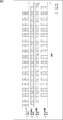
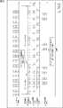
- Fig. 1 shows an example of a time chart for transmission at the sampling frame rate without dynamically changing the frame rate.
- processing is performed in order from the top. That is, first capture & CODEC (A in FIG. 1) is performed, then transmission device transmission (B in FIG. 1) is performed, reception device reception (C in FIG. 1) is performed, and finally reception device.
- Reproduction (D in FIG. 1) is performed.
- the direction from left to right indicates a time series.
- the processing time of each packet is represented by a square mark, the upper number in the square mark indicates a frame ID (Frame ID), that is, a serial number for each frame, and the lower number indicates a time stamp value.
- Each frame is assumed to be composed of 4 packets and 2 compression encoded blocks. The time stamp value is set incremented by 10 counts for each compression coding block.
- the playback interval (reproduction frame rate) is the same as the capture interval (capture frame rate) in capture & CODEC (A in FIG. 1). Packets necessary for reproduction are already received at the reproduction time in the reception apparatus reproduction (D in FIG. 1). That is, in this case, the receiving apparatus can perform synchronous reproduction in the receiving apparatus reproduction (D in FIG. 1).
- the transmission device transmits the image data after converting the frame rate of the image data to a frame rate lower than the sampling frame rate
- the transmission rate is smoothed by the transmission device or a transmission relay device (so-called router). Done. Therefore, there is a possibility that the time taken to transmit all the data of each picture varies depending on the post-conversion frame rate. As a result, there is a possibility that a problem may occur in synchronous reproduction in the receiving apparatus when the frame rate is dynamically changed.
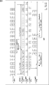
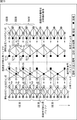
- FIG. 2 is a diagram showing an example of a time chart when the frame rate is dynamically converted.
- the processing flow is basically the same as in FIG. 1, but in this case, as shown in FIG. 2B, the transmission apparatus frame rate conversion processing output is performed in the transmission apparatus, and the frame number (Frame ID) ) After 3, some frames are thinned out and the frame rate is converted to 1/3.
- the transmission rate is smoothed before transmission by the transmission apparatus (C in FIG. 2), and the packet interval of the part subjected to frame rate conversion is longer than the previous packet interval.
- the packet interval for reception by the reception device (D in FIG. 2) also changes in the same manner as in transmission by the transmission device (C in FIG. 2). Therefore, in reproduction by the receiving apparatus (E in FIG. 2), reproduction is started when the first compressed encoded block data is received, and thereafter, synchronous reproduction is performed according to the difference value with respect to the time stamp of the first packet. Then, when the first compression-coded block of frame number (Frame ID) 3 is reproduced, the compression-coded block data of frame number (Frame ⁇ ID) 3 is not complete, and an incomplete video may be reproduced. was there. That is, there is a possibility that the video is broken and the synchronized reproduction cannot be realized.
- the receiving apparatus assumes a transmission time of picture data when the frame rate is the lowest, and is sufficient for the transmission time. It is conceivable to perform a synchronized reproduction by storing received data with a sufficient amount of data in a buffer.
- FIG. 3 is a diagram illustrating an example of a time chart in this case.
- the frame rate is dynamically converted on the transmission device side as in the case of FIG. 2.
- the receiving apparatus buffers the received data and reproduces it as shown in Receiving apparatus reproduction (E in FIG. 3), so that a predetermined delay is obtained in advance. Have time.
- the playback time of the first compression-coded block of frame number (Frame ID) 3 is later than in the case of FIG. 2, so that the compression-coded block data of frame number (Frame ID) 3 is complete, and the failure occurs. It is suppressed.
- the present invention has been proposed in view of such circumstances, and an object thereof is to more reliably realize low-delay transmission synchronized reproduction of images.
- a frame rate conversion means for converting a frame rate of moving image data in which a time stamp synchronized with a sampling time is assigned to each frame, and a frame rate conversion by the frame rate conversion means. Updating the time stamp of each frame after the frame rate conversion to a time before the time stamp before the update of the next frame after the frame rate conversion; and the time stamp is updated by the update means.
- An information processing apparatus comprising: transmission means for transmitting the updated moving image data to another information processing apparatus that determines a reproduction time of each frame based on the time stamp.
- the updating means updates the time stamp of each frame after the frame rate conversion to a time stamp of a frame positioned immediately before the next frame after the frame rate conversion in the state before the frame rate conversion. can do.
- the frame rate conversion means can convert the frame rate to a desired frame rate by thinning out part of the frame data from the moving image data.
- the frame rate conversion means can convert the frame rate to a desired frame rate by synthesizing a plurality of frames of the moving image data.
- the frame rate converting means converts a frame rate of moving image data in which an ID value synchronized with a sampling time of each frame is assigned for each predetermined data unit, and the updating means includes a frame rate by the frame rate converting means.
- the ID value after the frame rate conversion is updated, and the transmission means uses the moving image data in which the ID value is updated by the update means, and the reproduction time of each frame as the ID value.
- the information can be transmitted to another information processing apparatus determined based on the information.
- the frame rate conversion means converts the frame rate of the moving image data in which each frame is assigned a time stamp synchronized with the sampling time, and the update means converts the frame rate.
- the time stamp of each frame after frame conversion is updated to a time before the time stamp before the update of the next frame after the frame rate conversion, and the transmission means updates the time stamp.
- the moving image data is transmitted to another information processing apparatus that determines a reproduction time of each frame based on the time stamp.
- a frame rate converting means for converting a frame rate of moving image data in which a time stamp synchronized with a sampling time is assigned to each frame, and a frame after frame rate conversion by the frame rate converting means.
- Frame information that includes at least one of a rate and the number of frames skipped indicating the number of frames deleted by frame rate conversion by the frame rate conversion means, and is information for specifying the frame rate conversion.
- An adding unit for adding the frame rate converted by the rate converting unit to the moving image data; the moving image data to which the frame information has been added by the adding unit; the reproduction time of each frame; the time stamp; Sampling of image data Over DOO, and an information processing apparatus including a transmitting means for transmitting to another information processing apparatus is determined based on the frame rate or the frame skip number after the frame rate conversion that is included in the frame information.
- the frame rate converting means converts a frame rate of moving image data in which an ID value synchronized with a sampling time of each frame is assigned for each predetermined data unit, and the transmitting means converts the frame information by the adding means.
- the added moving image data is based on the playback time of each frame based on the ID value, the sampling rate of the moving image data, and the frame rate after the frame rate conversion included in the frame information or the number of frame skips. Can be transmitted to another information processing apparatus determined by the
- the frame rate conversion means converts the frame rate of the moving image data in which a time stamp synchronized with the sampling time is assigned to each frame
- the addition means converts the frame rate after the frame rate conversion.
- Frame information that includes at least one of the frame rate and the number of frame skips indicating the number of frames deleted by the frame rate conversion, and that specifies the frame rate conversion is converted into the frame rate converted frame information.
- the transmission means adds the moving image data to which the frame information is added to the moving image data, the reproduction time of each frame is included in the time stamp, the sampling rate of the moving image data, and the frame information.
- the frame rate after the frame rate conversion or the frame rate An information processing method for transmitting the other information processing apparatus for determining based on Musukippu number.
- a time stamp synchronized with a sampling time of each frame transmitted from another information processing apparatus, and a frame rate after frame rate conversion performed in the other information processing apparatus
- moving image data including at least one of the number of frame skips indicating the number of frames deleted by the frame rate conversion, to which frame information that is information for specifying the frame rate conversion is added.
- the reproduction time determining means divides a value obtained by subtracting 1 from an integer value of a quotient obtained by dividing the sampling rate by the frame rate included in the frame information by the sampling rate, and is calculated from the time stamp. A time delayed from the time by the division result can be determined as the reproduction time.
- the reproduction time determining means is configured to reproduce a time obtained by delaying the number of frame skips included in the frame information by a time corresponding to a division result of a sampling frame rate of the moving image data from the reproduction time calculated from the time stamp. The time can be determined.
- the receiving means receives an ID value for each predetermined data unit that is transmitted from another information processing apparatus and synchronized with a sampling time of each frame, and moving image data to which the frame information is added, and performs the reproduction
- the time determination unit uses the ID value, the sampling rate of the moving image data, and the frame rate after the frame rate conversion included in the frame information or the number of frame skips received by the reception unit.
- the reproduction time of each frame of moving image data can be determined.
- the receiving unit transmits a time stamp synchronized with a sampling time of each frame transmitted from another information processing apparatus, and frame rate conversion performed in the other information processing apparatus. Including at least one of the frame rate after the frame rate and the number of frame skips indicating the number of frames deleted by the frame rate conversion, to which the frame information that is information specifying the frame rate conversion is added.
- the image data is received, and the reproduction time determining means receives the time stamp, the sampling rate of the moving image data, and the frame rate after the frame rate conversion included in the frame information or the number of frame skips.
- Information processing for determining the reproduction time of each frame of the moving image data It is a method.
- the frame rate of moving image data in which a time stamp synchronized with the sampling time is assigned to each frame is converted, and the time of each frame after frame conversion is converted according to the conversion of the frame rate.
- the stamp is updated to the time before the time stamp before the update of the next frame after the frame rate conversion, and the moving image data with the updated time stamp determines the playback time of each frame based on the time stamp. It is transmitted to another information processing apparatus.
- the frame rate of moving image data in which a time stamp synchronized with the sampling time is assigned to each frame is converted, and the frame rate after frame rate conversion is deleted by frame rate conversion.
- the frame information that includes at least one of the frame skip numbers indicating the number of frames and specifies frame rate conversion is added to the frame rate converted moving image data, and the frame information is added.
- the moving image data determines the playback time of each frame based on the time stamp, the sampling rate of the moving image data, and the frame rate or the number of frame skips after frame rate conversion included in the frame information. Sent.
- a time stamp synchronized with the sampling time of each frame transmitted from another information processing apparatus, and a frame rate after frame rate conversion performed in the other information processing apparatus
- moving image data including at least one of frame skip counts indicating the number of frames deleted by frame rate conversion and including frame information, which is information for specifying frame rate conversion
- time The playback time of each frame of the received moving image data is determined using the stamp, the sampling rate of the moving image data, and the frame rate or the frame skip number after frame rate conversion included in the frame information.
- information can be processed.
- low-delay transmission synchronized playback of images can be realized more reliably.
- disassembly level 2. It is a basic diagram which shows roughly the flow of the wavelet transformation and wavelet inverse transformation by this invention. It is a block diagram which shows the structural example of the decoding part to which this invention is applied.
- First embodiment time stamp update
- Second embodiment encode process / decoding process
- Third embodiment providing frame rate information
- Fourth embodiment providing frame skip count
- Fifth embodiment personal computer
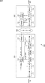
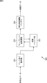
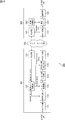
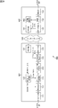
- FIG. 4 is a block diagram showing a configuration example of an information processing system to which the present invention is applied.
- the information processing system 100 is a system that performs low-delay transmission synchronous reproduction of moving images from the transmission apparatus 101 to the reception apparatus 102 via the Internet network 103. That is, the transmission apparatus 101 encodes the captured moving image, transfers the obtained encoded data to the reception apparatus 102 via the Internet network 103, and the reception apparatus 102 receives the encoded data and decodes it. And synchronously play back moving images.
- the transmission apparatus 101 encodes image data using a low-delay encoding method.
- the receiving apparatus 102 decodes the encoded data using a low-delay decoding method corresponding to the encoding method. Further, the transmission apparatus 101 dynamically changes the frame rate of the image data according to the bandwidth of the transmission path. The receiving apparatus 102 reproduces the image data at the frame rate changed by the transmitting apparatus 101 (performs synchronous reproduction).
- the receiving apparatus 102 adjusts the reproduction timing of each frame in accordance with the transmission timing shift caused by the smoothing of the transmission rate so that the reproduced image does not fail even at the low frame rate portion.
- the transmission apparatus 101 includes a capture unit 111, an encoding unit 112, a frame rate conversion unit 113, a time stamp control unit 114, a smoothing unit (Shaper) 115, an RTP transmission unit (RTP TX) 116, and an RTCP (RTP Control Protocol).
- Unit 121 and transmission rate control unit 122 are included in The transmission apparatus 101.
- the capture unit 111 captures the moving image (video IN) input to the transmission apparatus 101 at a predetermined frame rate, and supplies the data to the encoding unit 112.
- the encoding unit 112 encodes the image data supplied from the capture unit 111 with a predetermined encoding method at an encoding rate (Encode ⁇ ⁇ ⁇ Rate) specified by the transmission rate control unit 122.
- the encoding unit 112 calculates a time stamp value synchronized with the capture time for each piece of encoded data in the encoding unit. This time stamp value is referred to when the moving image is reproduced by the receiving device.
- the capture time means that the uncompressed moving image data captured by the capture device is input to the encoding unit 112 of the transmission apparatus 101 via a serial interface such as HD-SDI (High-Definition-Serial-Digital-Interface).
- HD-SDI High-Definition-Serial-Digital-Interface
- the time when the head data of each coding block is input is shown. That is, a plurality of encoded blocks having different capture times may exist in the same frame.
- a time stamp may be set for each encoding block which is a unit of encoding processing, a time stamp may be set for each frame, or a plurality of frames may be set.
- a time stamp may be set every time.
- the encoding unit 112 converts the encoded data obtained by encoding the image data into an RTP packet, adds the calculated time stamp value to the RTP packet as an RTP time stamp, and supplies the RTP packet to the frame rate conversion unit 113.
- the frame rate conversion unit 113 is a frame specified by the transmission rate control unit 122 by thinning out the frame rate of the encoded data supplied from the encoding unit 112, for example, a part of the frame (encoded data thereof). Convert to rate (Frame Rate).
- the frame rate conversion unit 113 converts the frame rate by image composition processing such as thinning processing and addition averaging processing, for example.
- the frame rate conversion unit 113 supplies the encoded data with the converted frame rate to the time stamp control unit 114.
- the frame rate conversion unit 113 omits the conversion process and converts the encoded data into This is supplied to the time stamp control unit 114.
- the time stamp control unit 114 adjusts the time stamp value (RTP time stamp) in accordance with a change in frame rate (such as a frame thinning rate). As will be described later, the receiving apparatus 102 reproduces the data at a time corresponding to the time stamp value. The time stamp control unit 114 updates the time stamp value to a value that does not cause the image to fail in this reproduction, as necessary. When the time stamp value is adjusted, the time stamp control unit 114 supplies the encoded data packet to the smoothing unit 115.
- a change in frame rate such as a frame thinning rate
- the smoothing unit 115 smoothes the transmission rate of the packet to a transmission rate specified by the transmission rate control unit 122. That is, the smoothing unit 115 temporarily holds the packet supplied from the time stamp control unit 114 and has a predetermined timing at which the transmission rate of the packet becomes a transmission rate (Transmission Rate) specified by the transmission rate control unit 122. The packet is supplied to the RTP transmitter 116 (at a predetermined time interval).
- the RTP transmission unit 116 transmits the packet supplied from the smoothing unit 115 to the receiving device 102 via the Internet network 103.
- the RTCP unit 121 communicates with the RTCP unit 141 of the receiving apparatus 102 via the Internet network 103, and acquires network status information for confirming the usable bandwidth of the Internet network 103 and the like. For example, the RTCP unit 121 exchanges network status information with the RTCP unit 141 by transmitting / receiving an RTCP / Sender / Report (SR) packet and an RTCP / Receiver / Report (RR) packet described in IETF / RFC / 3550.
- the network status information may include any information as long as it is information related to communication on the Internet network 103. For example, a round-trip transmission delay (so-called RTT (Round Trip Time)), a packet loss rate, and the like may be included. Of course, other parameters may be included.
- the RTCP unit 121 supplies the network status information thus exchanged to the transmission rate control unit 122.
- the transmission rate control unit 122 determines the encoding rate of the encoding process, the frame rate after frame rate conversion, the transmission rate of the packet, and the like based on the network status information supplied from the RTCP unit 121.
- the transmission rate control unit 122 supplies the encoding rate to the encoding unit 112, supplies the frame rate to the frame rate conversion unit 113, and supplies the transfer rate to the smoothing unit 115.
- the receiving apparatus 102 includes an RTP reception (RTP RX) unit 131, a reception buffer 132, a decoding unit 133, an RTCP unit 141, and a synchronization control unit 142.
- RTP RX RTP reception
- the RTP reception unit 131 communicates with the transmission device 101 via the Internet network 103, receives the packet transmitted from the RTP transmission unit 116, and supplies it to the reception buffer 132. Also, the RTP receiver 131 supplies information (Packet info) regarding the packet reception status to the RTCP unit 141.
- Packet info information regarding the packet reception status to the RTCP unit 141.
- the reception buffer 132 holds the packet supplied from the RTP reception unit 131.
- the reception buffer 132 is controlled by the synchronization control unit 142, extracts encoded data from the packet at a predetermined timing, and supplies the extracted data to the decoding unit 133.
- the decoding unit 133 decodes the encoded data supplied from the reception buffer 132 by a method corresponding to the encoding method of the encoding unit 112, and the obtained baseband image data is determined by the synchronization control unit 142. Output (playback) at the playback time (synchronous playback time).
- the RTCP unit 141 exchanges network status information with the RTCP unit 121 of the transmission apparatus 101 via the Internet network 103.
- the RTCP unit 141 supplies network status information including information regarding the reception status of the packet supplied from the RTP receiving unit 131 to the RTCP unit 121 as network status information.
- the synchronization control unit 142 determines the synchronous reproduction time of the encoded data of the encoding unit held in the reception buffer 132.
- the synchronization control unit 142 calculates the synchronized playback time using the time corresponding to the time stamp value of the encoded data.
- the synchronization control unit 142 supplies the synchronous reproduction time calculated as described above to the reception buffer 132, and supplies it to the decoding unit 133 together with the encoded data corresponding to the synchronous reproduction time.
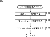
- the transmission rate control unit 122 executes rate control processing at a predetermined timing, and determines various rates based on the network status information supplied from the RTCP unit 121.
- the transmission rate control unit 122 determines the transmission rate in step S101.
- the method for determining the transmission rate is arbitrary.
- the transmission rate may be determined according to the method shown in IETF RFC3448 “TCP Friendly Rate Control (TFRC): Protocol Specification”.
- the transmission rate control unit 122 determines the frame rate after frame conversion in the frame rate conversion unit 113 based on the transmission rate determined in step S101.
- the frame rate after this conversion becomes the frame rate during transmission (transmission frame rate).
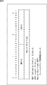
- the method for determining the frame rate is arbitrary. For example, a frame rate that optimizes the quality perceived by the user at each transmission rate is set in advance as shown in the graph of FIG. 6, and a frame rate corresponding to the transmission rate is set according to the graph. May be. It is desirable to change (set) the frame rate-transmission rate setting graph according to the characteristics of the application, the encoding unit, and the like.
- the data indicating the relationship between transmission rate and frame rate conversion as in the graph of FIG. 6 may be table information using representative points, or may be a mathematical expression or the like.
- the transmission rate control unit 122 determines the encoding rate.
- the encoding unit 112 of the transmission apparatus 101 performs the encoding process using the sampling frame rate (capture rate) of the original moving image as the frame rate regardless of the frame rate specified by the transmission rate control unit 122. .
- the frame rate conversion unit 113 performs frame rate conversion by thinning processing for thinning out some frames. Therefore, the transmission rate control unit 122 sets the encoding rate to R_e (bps), the transmission rate to R_t (bps), and the sampling frame rate to f_s () in order to make the data rate after frame rate conversion equal to the transmission rate.
- fps) and the converted frame rate is f_t (fps)
- the encoding rate R_e is set so as to satisfy the following expression (1).
- each rate may be controlled by a method other than that described above.
- the encoding unit 112 has a frame rate conversion function
- the transmission rate control unit 122 sets the encoding rate and the transmission rate to be equal, and supplies the encoding rate and the converted frame rate to the encoding unit 112. Also good.
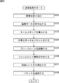
- Each unit of the transmission apparatus 101 executes transmission processing, and encodes and transmits image data at a rate based on rate control as described above.
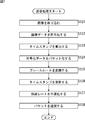
- An example of the flow of transmission processing will be described with reference to the flowchart of FIG.
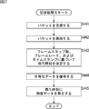
- step S121 the capture unit 111 captures a moving image (video data input from a video IN that is a video input IF via a video camera or the like) supplied from the outside.
- step S122 the encoding unit 112 encodes the supplied image data at the encoding rate specified by the transmission rate control unit 122.
- step S123 the encoding unit 112 calculates a time stamp value synchronized with the capture time based on the capture time information.
- step S124 the encoding unit 112 divides the encoded data obtained by encoding into, for example, a plurality of RTP packets.
- the encoding unit 112 adds the time stamp value calculated by the process of step S123 to the RTP packet as an RTP time stamp.
- step S125 the frame rate conversion unit 113 converts the frame rate specified by the transmission rate control unit 122, for example, by thinning out some frames.
- sampling frame rate f_s (fps) is converted to the converted transmission frame rate f_t (fps) will be described.
- f_s and f_t satisfy the relationship of the following formula (2).
- variable M indicates the frame decimation ratio.
- the frame rate conversion unit 113 extracts M-frames from the pre-conversion data at a frequency of one frame, and generates post-conversion data using the extracted frames.
- the pre-conversion frame data is F (n) (n is the frame serial number)
- the post-conversion frame data is F ′ (n) (n is the post-conversion frame serial number)
- the pre-conversion data D_o is expressed by the following equation (3 )
- the post-conversion data D′ _t can be expressed as the following formula (4).
- the frame rate conversion unit 113 may convert the frame rate by a method other than the frame thinning process.
- the frame rate conversion method is arbitrary.
- the frame rate may be converted by combining a plurality of consecutive frames by image combining processing such as addition averaging processing to reduce the number of frames.
- step S125 If the frame rate specified by the transmission rate control unit 122 is the same as the frame rate before conversion (sampling frame rate), the process of step S125 is omitted.
- step S126 the time stamp control unit 114 controls, for example, the RTP time stamp included in the RTP header part.
- the time stamp control unit 114 performs time stamp adjustment based on the frame decimation rate M of the converted frame data converted by the frame rate conversion unit 113.
- the pre-conversion frame data is F (n) (n is the serial number of the pre-conversion frame)
- the post-conversion frame data is F ′ (m) (m is the serial number of the post-conversion frame data)
- the encoded block before conversion The data is B (n, k)
- the encoded block data after conversion is B ′ (m, k) (k is the serial number of the encoded block in the frame data).
- the time stamp value of the encoded block data B (n, k) before conversion is assumed to be TS (n, k).
- a time stamp value before time stamp control of the encoded block data B ′ (m, k) after conversion is TS ′ (m, k).
- the time stamp value after time stamp control of the encoded block data B ′ (m, k) after conversion is TS ′′ (m, k).
- the frame decimation ratio is M.
- the converted frame data F ′ (m), the converted encoded block data B ′ (m, k), and the converted encoded block data B ′ (m, k) before time stamp control are respectively expressed as the following formulas (5) to (7).
- the time stamp value TS ′′ (m, k) after time stamp control of the converted encoded block data B ′ (m, k) is the converted frame data F ′ (m) and the next converted frame data F ′. It is adjusted according to the number of pre-conversion frames (M ⁇ 1) thinned out from (m + 1).
- the time stamp value TS ′′ (m, k) after the time stamp control is expressed by the following equation (8).
- the time stamp value after time stamp control is set to the same time stamp value as the encoded block data that matches the last pre-conversion frame data of the pre-conversion frame data thinned out after the corresponding frame.
- the time stamp value is not changed before and after the time stamp control.
- the time that the corresponding frame should have been allocated to the thinned frame is also used by smoothing the transmission rate. It is assumed that the data is smoothed and transmitted. Therefore, the last pre-conversion frame data in the pre-conversion frame data thinned out after the corresponding frame is matched so that it is synchronized with the arrival time of the end data of each smoothed frame data.
- the same time stamp value as the compressed encoded block data to be set is set.
- the smoothing unit 115 adjusts the packet transmission timing and smoothes the transmission rate. For example, the smoothing unit 115 smoothes the transmission rate by the same processing as Token-Bucket described in ITU-T / Recommendation / Y.1221 / Traffic / control / and / congestion / control / in / IP-based / networks.
- step S1208 the RTP transmitter 116 transmits a packet at a timing controlled by the smoother 115.
- the transmission process is terminated.
- each packet is transmitted sequentially.
- the processing of each step described above is executed as soon as preparation is completed, and the processing is repeated for the next data as soon as the processing in each processing unit is completed. Therefore, the processes described above are executed in parallel as appropriate.
- the smoothing process may be performed in a relay device such as a router or Ethernet (registered trademark) Switch outside the transmission device 101.
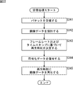
- the receiving device 102 executes reception processing and receives the packet transmitted as described above.
- the RTP reception unit 131 of the reception apparatus 102 receives the RTP packet transmitted from the transmission apparatus 101 in step S141.
- the reception buffer 132 holds the received RTP packet.
- step S143 the synchronization control unit 142 determines the synchronized reproduction time based on the time stamp information of each RTP packet stored in the reception buffer 132, for example.
- the time stamp value of the first RTP packet is TS_init
- the reception time of the RTP packet is T_init (sec)
- the RTP time stamp frequency is f_rtp (Hz)
- the playback offset time is T_play (sec)
- the reception time of the RTP packet with the time stamp value TS is T_r (TS).
- the reproduction time T_p (TS) of the RTP packet with the time stamp value TS can be calculated as in the following equation (9), for example.
- the playback time T_p (TS) of the RTP packet may be calculated by other methods.
- the playback offset time T_play indicates the offset time from the packet reception time to the playback time. This parameter is for reflecting a processing delay in the receiving apparatus 102.
- the transmission / reception device time offset time T_skew is an offset time for absorbing a difference in system clock frequency between the transmission / reception devices. For example, the value of the transmission / reception device time offset time T_skew is “0” immediately after the start of stream reception, and is corrected as shown in the following equation (10) at regular intervals.
- the synchronization control unit 142 causes the reception unit 132 to supply the decoding unit 133 with the synchronized playback time determined as described above and the compressed moving image data stored in the RTP packet.
- the decoding unit 133 decodes the encoded data in step S144.
- the decoding unit 133 reproduces the image data obtained by decoding at the synchronized reproduction time determined by the synchronization control unit 142, and outputs it from the video output IF (video OUT).
- the output data is output to a video display device such as a display, for example.
- each received packet is sequentially processed and output as image data.
- the processing of each step described above is executed as soon as preparation is completed, and the processing is repeated for the next data as soon as the processing in each processing unit is completed. Therefore, the processes described above are executed in parallel as appropriate.
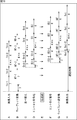
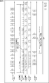
- FIG. 9 is a diagram for explaining an example of timing at which each process in data transmission is executed when the present invention is applied.
- FIG. 9 is a diagram corresponding to FIGS. 1 to 3, and basically has the same contents as those diagrams.
- capture & CODEC A in FIG. 9 indicating the output timing of image capture and encoding
- transmission apparatus frame rate conversion indicating the output timing of frame rate conversion
- Process output B in FIG. 9
- Time stamp control process output C in FIG. 9 indicating the output timing of the time stamp update
- Transmitter transmission D in FIG. 9) indicating the packet transmission timing
- Receiving device reception E in FIG. 9) indicating the reception timing of the packet
- “Reception device reproduction” F in FIG. 9) indicating the reproduction output timing of the image data
- the transmission apparatus 101 captures and encodes each compression-coded block at regular intervals by “capture & CODEC” (A in FIG. 9) processing, and performs “transmission apparatus frame rate conversion” processing. (B in FIG. 9), the frame is thinned to a frame rate that is one third of the sampling frame rate. Also, the “time stamp control” process (C in FIG. 9) converts the time stamp value according to the frame decimation ratio, and the packet of data smoothed by the smoothing process is transmitted to the “transmitting device” (FIG. 9). 9 is transmitted at the timing shown in D).
- the receiving apparatus 102 receives the packet at the timing of “receiving apparatus reception” (E in FIG. 9), and reproduces the packet at the timing of “reproducing receiving apparatus” (F in FIG. 9) in accordance with the processing of the “synchronization control unit”. . At this time, it is assumed that “reception device reproduction” is not performed unless the “reception device reception” processing of all data in the encoded block is completed.
- the playback video may be broken or an unnecessary increase in delay may occur. Since the time stamp is updated according to the frame rate after the change, the receiving apparatus 102 that performs reproduction at the timing based on the updated time stamp, as shown in F of FIG. Regardless of the height, it is possible to reliably reproduce the image data without synchronization failure.
- the receiving apparatus 102 can realize low-delay transmission without causing the failure of the synchronized playback.
- the frame rate can be dynamically changed while performing low-delay transmission synchronous reproduction. Therefore, since the frame rate can be dynamically changed for transmission rate control, the image quality per image can be set higher than when transmission rate control is performed only by the image quality parameter, and the motion This is effective when transmitting a small number of moving images.
- the information processing system 100 can perform low-delay transmission synchronous reproduction while dynamically changing the frame rate even if the transmission rate is smoothed, so there is no need to perform burst transmission of data and Occurrence of packet loss can be suppressed.
- each device of the information processing system 100 can more reliably realize low-delay transmission synchronized playback of images.
- the transmission apparatus 101 adds a time stamp synchronized with the sampling time to the moving image data, and the receiving apparatus 102 reproduces each frame of the moving image data in synchronization with the time stamp.
- the information for controlling the reproduction time may be information other than the time stamp as long as the information is synchronized with the sampling time.
- an ID value assigned to moving image data for each predetermined data unit such as a frame ID or an intra-frame block ID may be used. If the sampling rate is clear, the receiving apparatus 102 can obtain the same information as the time stamp from these frame IDs and intra-frame block IDs.
- the transmission apparatus 101 updates the ID value assigned to the moving image data for each predetermined data unit synchronized with the sampling time of each frame of the moving image data in accordance with the frame rate conversion described above. As in the case of the time stamp, the reproduction timing in the receiving apparatus 102 can be controlled. That is, each device of the information processing system 100 can more reliably realize low-delay transmission synchronized playback of images.
- the encoding method of the encoding unit 112 (decoding method of the decoding unit 133) is basically arbitrary, and any method can be applied.
- each picture of a moving image proposed in Patent Document 1 Alternatively, a moving image encoding method may be used in which encoding is performed using several lines as one encoded block.
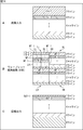
- FIG. 10 is a block diagram showing a detailed configuration example of the encoding unit 112 to which the present invention is applied.
- the encoding unit 112 includes a wavelet transform unit 211, a midway calculation buffer unit 212, a coefficient rearranging buffer unit 213, a coefficient rearranging unit 214, an entropy encoding unit 215, and a time stamp calculating unit 216. And a packetizing part 217.
- the image data input to the encoding unit 112 is temporarily stored in the midway calculation buffer unit 212 via the wavelet transform unit 211.
- the wavelet transform unit 211 performs wavelet transform on the image data stored in the midway calculation buffer unit 212. That is, the wavelet transform unit 211 reads out the image data from the midway calculation buffer unit 212 and performs filtering using an analysis filter to generate low-frequency component and high-frequency component coefficient data.
- the data is stored in the calculation buffer unit 212.
- the wavelet transform unit 211 has a horizontal analysis filter and a vertical analysis filter, and performs an analysis filter process on the image data group in both the screen horizontal direction and the screen vertical direction.
- the wavelet transform unit 211 reads the low-frequency component coefficient data stored in the midway calculation buffer unit 212 again, performs a filtering process on the read coefficient data with an analysis filter, and performs high-frequency component and low-frequency component data processing. Further generate coefficient data.
- the generated coefficient data is stored in the midway calculation buffer unit 212.
- the wavelet transform unit 211 reads the coefficient data from the midway calculation buffer unit 212 and writes the read coefficient data into the coefficient rearranging buffer unit 213.
- the coefficient rearranging unit 214 reads the coefficient data written in the coefficient rearranging buffer unit 213 in a predetermined order, and supplies it to the entropy encoding unit 215.
- the entropy encoding unit 215 quantizes the supplied coefficient data by a predetermined method, and encodes the data by a predetermined entropy encoding method such as Huffman encoding or arithmetic encoding.
- the entropy encoding unit 215 supplies the generated encoded data to the time stamp calculation unit 216.
- the time stamp calculation unit 216 calculates the time stamp value of the supplied encoded data based on the capture time information of the data. That is, the time stamp calculation unit 216 calculates a time stamp value synchronized with the capture time. The time stamp calculation unit 216 supplies the calculated time stamp value to the packetizing unit 217 together with the encoded data.
- the packetizing unit 217 converts the supplied encoded data into RTP packets, and adds a time stamp value to each packet as an RTP time stamp value.
- the packetizing unit 217 supplies the generated packet to the frame rate conversion unit 113.
- the wavelet transform unit 211 in FIG. 10 will be described in more detail.
- the wavelet transform will be schematically described.
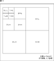
- the wavelet transform for image data as schematically shown in FIG. 11, the process of dividing the image data into a high spatial frequency band and a low spatial frequency is performed on the low spatial frequency band data obtained as a result of the division. And repeat recursively. In this way, efficient compression coding can be performed by driving data of a low spatial frequency band into a smaller area.
- “L” and “H” represent a low-frequency component and a high-frequency component, respectively.
- the order of “L” and “H” indicates a band obtained by dividing the front side in the horizontal direction. The band resulting from division in the vertical direction is shown.
- the numbers before “L” and “H” indicate the hierarchy of the area, and the lower-frequency component hierarchy is represented by a smaller value.
- the maximum value of this hierarchy indicates the current division level (number of divisions) of the wavelet transform.
- the processing is performed step by step from the lower right region to the upper left region of the screen, and the low frequency component is driven. That is, in the example of FIG. 11, the lower right region of the screen is the region 3HH having the lowest low frequency component (the highest frequency component is included), and the upper left region obtained by dividing the screen into four is further divided into four regions. The upper left region is further divided into four parts. The region at the upper left corner is a region 0LL that includes the most low frequency components.
- the wavelet transform unit 211 normally performs the above-described processing using a filter bank composed of a low-pass filter and a high-pass filter. Since a digital filter usually has an impulse response having a plurality of taps, that is, a filter coefficient, it is necessary to buffer in advance input image data or coefficient data that can be filtered. Similarly, when wavelet transform is performed in multiple stages, it is necessary to buffer the wavelet transform coefficients generated in the previous stage as many times as can be filtered.
- this wavelet transform As a specific example of this wavelet transform, a method using a 5 ⁇ 3 filter will be described. This method using a 5 ⁇ 3 filter is also adopted in the JPEG (Joint Photographic Experts Group) 2000 standard, and is an excellent method in that wavelet transform can be performed with a small number of filter taps.
- JPEG Joint Photographic Experts Group 2000 standard
- the impulse response (Z conversion expression) of the 5 ⁇ 3 filter is obtained from the low-pass filter H 0 (z) and the high-pass filter H 1 (z) as shown in the following equations (11) and (12). Composed.
- H 0 (z) ( ⁇ 1 + 2z ⁇ 1 + 6z ⁇ 2 + 2z ⁇ 3 ⁇ z ⁇ 4 ) / 8 (11)
- H 1 (z) ( ⁇ 1 + 2z ⁇ 1 ⁇ z ⁇ 2 ) / 2 (12)
- the coefficients of the low frequency component and the high frequency component can be directly calculated.
- the calculation of the filter processing can be reduced.
- the part shown as the analysis filter on the left side of the figure is the filter of the wavelet transform unit 211 in FIG.
- a portion shown as a synthesis filter on the right side of the figure is a filter of a wavelet inverse transform unit described later.
- a pixel is scanned from the upper left corner of the screen toward the right end from the left end of the screen to form one line, and scanning for each line is performed from the upper end of the screen. It is assumed that one screen is constructed by moving toward the lower end.
- the leftmost column shows pixel data at corresponding positions on the line of the original image data arranged in the vertical direction. That is, the filter processing in the wavelet transform unit 211 is performed by vertically scanning pixels on the screen using a vertical filter.
- the second column from the left end shows a high frequency component output based on the pixels of the left end original image data, and the third column from the left end shows a low frequency component output based on the original image data and the high frequency component output.
- the high-frequency component coefficient data is calculated based on the pixels of the original image data as the first-stage filter processing, and is calculated by the first-stage filter processing as the second-stage filter processing.
- the low-frequency component coefficient data is calculated based on the high-frequency component coefficient data and the pixels of the original image data.
- the calculated coefficient data of the high frequency component is stored in the coefficient rearranging buffer unit 213 in FIG. Further, the calculated coefficient data of the low frequency component is stored in the midway calculation buffer unit 212 of FIG.
- the coefficient rearranging buffer unit 213 is shown as a portion surrounded by a one-dot chain line, and the midway calculation buffer unit 212 is shown as a portion surrounded by a dotted line.
- the region HH and the region HL by the coefficient data obtained by further decomposing the high frequency component into the high frequency component and the low frequency component, and the low frequency component are further converted into the high frequency component and Four regions, the region LH and the region LL, are formed by the coefficient data decomposed into low-frequency components.
- the wavelet transform unit 211 divides the filter process by wavelet transform into processes for several lines in the vertical direction of the screen, and performs the process step by step in a plurality of times.
- the first process that is the process from the first line on the screen performs the filter process for 7 lines
- the second and subsequent processes that are the processes from the 8th line are performed every 4 lines. Filter processing is performed. This number of lines is based on the number of lines necessary for generating the lowest band component for one line after being divided into two, the high band component and the low band component.
- a collection of lines including other subbands necessary for generating one line of the lowest frequency component (coefficient data for one line of the subband of the lowest frequency component) is precinct ( Or a line block).
- the line indicates pixel data or coefficient data for one row formed in a picture or field corresponding to image data before wavelet transform, or in each subband.
- the precinct (line block) is a pixel data group corresponding to the number of lines necessary for generating coefficient data for one subband of the lowest frequency component after wavelet transformation in the original image data before wavelet transformation.
- the coefficient data group of each subband obtained by wavelet transforming the pixel data group.
- the coefficient Cc is calculated based on the coefficients C2 and C3 stored in the coefficient rearranging buffer unit 213 and the pixel data of the fifth line.
- the coefficient C3 is calculated based on the pixel data of the fifth line to the seventh line.
- the pixel data of the first line to the seventh line are required.
- the coefficient data already calculated in the previous filter processing and stored in the coefficient rearranging buffer unit 213 can be used, so the number of necessary lines is small. I'll do it.
- the coefficient C4 has already been calculated by the first filtering process described above, and is stored in the coefficient rearranging buffer unit 213.
- the coefficient Cc is already calculated by the first filtering process described above, and is stored in the midway calculation buffer unit 212. Therefore, in the second filtering process, only the filtering process for calculating the coefficient C8 is newly performed. This new filtering process is performed by further using the eighth to eleventh lines.
- the second and subsequent filtering processes can use the data calculated by the previous filtering process and stored in the midway calculation buffer unit 212 and the coefficient rearranging buffer unit 213. This is all you need to do.
- the original image data lines are copied by a predetermined method, and the number of lines is combined with the number of lines to be encoded.
- the encoded data can be obtained. It is possible to obtain a decoded image with low delay when transmitted.
- the first buffer corresponds to the midway calculation buffer unit 212 and is surrounded by a dotted line in FIG.
- the second buffer corresponds to the coefficient rearranging buffer unit 213 and is shown surrounded by a one-dot chain line in FIG. Since the coefficient stored in the second buffer is used in decoding, it is a target of entropy encoding processing in the subsequent stage.
- the coefficient data calculated by the wavelet transform unit 211 is stored in the coefficient rearranging buffer unit 213, is read out by the coefficient rearranging unit 214, and is read out in units of coding units. Sent to the conversion unit 215.
- coefficients are generated from the high frequency component side to the low frequency component side.
- the generation order of the coefficient data is always in this order (order from high to low) on the principle of wavelet transform.
- the coefficient data generated on the encoding side is rearranged from the lowest frequency component side to the higher frequency component side and supplied to the decoding side.
- the right side of FIG. 13 shows the synthesis filter side that performs inverse wavelet transform.
- the first synthesis process (inverse wavelet transform process) including the first line of the output image data on the decoding side includes the coefficients C4 and C5 of the lowest frequency component generated by the first filtering process on the encoding side. , Using the coefficient C1.
- the coefficient C5 and the coefficient C4 are combined to generate the coefficient Cf and store it in the buffer.
- the coefficient data generated in the order of the coefficient C1, the coefficient C2, the coefficient C3, the coefficient C4, and the coefficient C5 on the encoding side and stored in the coefficient rearranging buffer unit 13 is .. Are rearranged in the order of coefficient C5, coefficient C4, coefficient C1,... And supplied to the decoding side.
- the coefficient number on the encoding side is written in parentheses, and the line order of the synthesis filter is written outside the parentheses.
- the coefficient C1 (5) indicates the coefficient C5 on the left analysis filter side in FIG. 13 and the first line on the synthesis filter side.
- the decoding-side synthesis process using the coefficient data generated in the second and subsequent filter processes on the encoding side can be performed using the coefficient data supplied from the synthesis or encoding side during the previous synthesis process.
- the second synthesis process on the decoding side which is performed using the low-frequency component coefficients C8 and C9 generated by the second filtering process on the encoding side,
- the coefficients C2 and C3 generated by the filtering process are further required, and the second to fifth lines are decoded.
- coefficient data is supplied from the encoding side to the decoding side in the order of coefficient C9, coefficient C8, coefficient C2, and coefficient C3.
- the coefficient Cg is generated using the coefficient C8 and the coefficient C9 and the coefficient C4 supplied from the encoding side in the first synthesis process, and is stored in the buffer.
- a coefficient Ch is generated using the coefficient Cg, the coefficient C4 described above, and the coefficient Cf generated by the first combining process and stored in the buffer, and stored in the buffer.
- coefficient data generated on the encoding side in the order of coefficient C2, coefficient C3, (coefficient C4, coefficient C5), coefficient C6, coefficient C7, coefficient C8, and coefficient C9 are generated.
- coefficient C9, coefficient C8, coefficient C2, coefficient C3,... Are rearranged in this order and supplied to the decoding side.
- the coefficient data stored in the coefficient rearranging buffer unit 213 is rearranged in a predetermined order and supplied to the decoding unit, and the lines are decoded four lines at a time. .
- the coefficient data rearrangement process by the coefficient rearrangement unit 214 is performed, for example, by setting a read address when reading the coefficient data stored in the coefficient rearrangement buffer unit 213 in a predetermined order.
- the wavelet transform unit 11 as shown in FIG. 14A, the first filtering process is performed in the horizontal and vertical directions for the first to seventh lines of the input image data (see FIG. 14). In-1 of A).
- One line by C4 is arranged.
- the region HH, the region HL, and the region LH are arranged next to the coefficient data generated by the first filtering process.
- the first filtering process by the first to seventh lines on the encoding side is performed.
- the first line by the first synthesizing process on the decoding side is output (Out-1 in FIG. 14C).
- four lines are output on the decoding side (Out-2 in FIG. 14C).
- 8 lines are output on the decoding side with respect to the last filtering process on the encoding side.
- the coefficient data generated by the wavelet transform unit 211 from the high frequency component side to the low frequency component side is sequentially stored in the coefficient rearranging buffer unit 213.
- the coefficient rearranging unit 214 rearranges the coefficient data from the coefficient rearranging buffer unit 213 in the order necessary for the synthesis process. Read the coefficient data instead.
- the read coefficient data is sequentially supplied to the entropy encoding unit 215.
- the entropy encoding unit 215 sequentially encodes the supplied coefficient data, and supplies the generated encoded data to the time stamp calculation unit 216.
- the time stamp calculating unit 216 calculates the time stamp as described above, and the packetizing unit 217 packetizes as described above.
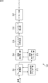
- FIG. 15 is a block diagram illustrating a configuration example of a decoding unit to which the present invention is applied.
- the decoding unit 133 includes an entropy decoding unit 221, a coefficient buffer unit 222, a wavelet inverse transform unit 223, and a reproduction time adjustment buffer 224.
- the entropy decoding unit 221 decodes the supplied encoded data by a decoding method corresponding to the encoding method by the entropy encoding unit 215 to obtain coefficient data.
- the coefficient data is stored in the coefficient buffer unit 222.
- the wavelet inverse transformation unit 223 performs synthesis filter processing (wavelet inverse transformation) using a synthesis filter using the coefficient data stored in the coefficient buffer unit 222 and stores the result of the synthesis filter processing in the coefficient buffer unit 222 again.
- the wavelet inverse transform unit 223 repeats this process according to the decomposition level and obtains decoded image data (output image data), it temporarily stores the decoded image data in the reproduction time adjustment buffer 224, and is determined by the synchronization control unit 142. Output at the synchronized playback time.
- the wavelet transform unit 211 When the encoding process is started, the wavelet transform unit 211 initializes the number A of the processing target precinct in step S201. In a normal case, the number A is set to “1”. When the setting is completed, in step S202, the wavelet transform unit 211 acquires image data of the number of lines (that is, one precinct) necessary to generate the Ath one line from the top in the lowest band subband.
- the wavelet transform unit 211 performs vertical analysis filtering processing for performing analysis filtering on the image data arranged in the vertical direction on the screen.
- the wavelet transform unit 211 further performs horizontal analysis filtering processing on the image data, in which analysis filtering processing is performed on the image data arranged in the horizontal direction on the screen in step S204.
- step S205 the wavelet transform unit 211 determines whether or not the analysis filtering process has been performed to the final level. If it is determined that the decomposition level has not reached the final level, the process returns to step S203, and the analysis filtering process in steps S203 and S204 is repeated for the current decomposition level.
- step S205 If it is determined in step S205 that the analysis filtering process has been performed to the final level, the process proceeds to step S206.
- step S206 the coefficient rearranging unit 214 rearranges the coefficients of the precinct A (A-th precinct from the top of the picture (frame or field)) in the order from low to high.
- step S207 the entropy encoding unit 215 performs entropy encoding on the coefficients for each line.
- step S208 the time stamp calculation unit 216 calculates a time stamp synchronized with the capture time of the encoded data obtained by entropy encoding.
- step S209 the packetizing unit 217 packetizes the encoded data. At this time, the packetizing unit 217 adds the calculated time stamp value to the packet.
- step S210 the packetizing unit 217 transmits the generated packet.
- step S211 the wavelet transform unit 211 increments the value of the number A by “1” to set the next precinct as a processing target.
- step S212 an unprocessed image input line is detected for the processing target picture (frame or field). Determine if it exists. If it is determined that there is an unprocessed image input line, the processing returns to step S202, and the subsequent processing is repeated for a new precinct to be processed.
- step S212 the processing from step S202 to step S212 is repeatedly executed, and each precinct is encoded. If it is determined in step S212 that there is no unprocessed image input line, the encoding process for the picture ends. The encoding process is newly started for the next picture.
- the wavelet transform unit 211 continuously performs vertical analysis filtering processing and horizontal analysis filtering processing up to the final level in units of precincts, so that it is held at one time (at the same time) as compared with the conventional method ( The amount of data that needs to be buffered) is small, and the amount of buffer memory to be prepared can be greatly reduced. Further, by performing the analysis filtering process to the final level, it is possible to perform subsequent processes such as coefficient rearrangement and entropy encoding (that is, coefficient rearrangement and entropy encoding can be performed in units of precincts). . Therefore, the delay time can be greatly reduced as compared with the method of performing wavelet transform on the entire screen.
- the entropy decoding unit 221 acquires encoded data supplied from the outside of the decoding unit 133 in step S231, and entropy decodes the encoded data for each line in step S232.
- step S233 the coefficient buffer unit 222 holds the coefficient data obtained by the decoding.
- step S ⁇ b> 234 the wavelet inverse transform unit 223 determines whether or not coefficient data for one precinct has been accumulated in the coefficient buffer unit 222. If it is determined that the coefficient data for one precinct has not been accumulated, the process returns to step S231, and the subsequent processes are executed. That is, the wavelet inverse transformation unit 223 waits until the coefficient data for one precinct is accumulated in the coefficient buffer unit 222.
- step S234 If it is determined in step S234 that coefficient data for one precinct has been accumulated in the coefficient buffer unit 222, the process proceeds to step S235.
- step S235 the wavelet inverse transform unit 223 reads the coefficient data held in the coefficient buffer unit 222 by one precinct.
- step S236 the wavelet inverse transform unit 223 performs vertical synthesis filtering processing on the read coefficient data, which performs synthesis filtering processing on the coefficient data arranged in the vertical direction on the screen.
- step S237 the wavelet inverse transform unit 223 performs horizontal synthesis filtering processing for performing synthesis filtering processing on the coefficient data arranged in the horizontal direction on the screen.
- step S238 the wavelet inverse transformation unit 223 determines whether or not the synthesis filtering processing has been completed up to level 1 (the value of the decomposition level is “1”), that is, whether or not the inverse transformation has been performed up to the state before the wavelet transformation. Determine. If it is determined that level 1 has not been reached, the process returns to step S236, and the filtering processes in steps S236 and S237 are repeated.
- step S238 If it is determined in step S238 that the inverse wavelet transform process has been completed up to level 1, the process proceeds to step S239.
- step S239 the wavelet inverse transformation unit 223 externally holds the image data obtained by the wavelet inverse transformation processing at the synchronous reproduction time determined by the synchronous control unit 142 while temporarily holding the image data in the reproduction time adjustment buffer 224. Output.
- step S240 the entropy decoding unit 221 determines whether to end the decoding process. If it is determined not to end the decoding process, the process returns to step S231, and the subsequent processes are repeated. Further, when it is determined in step S240 that the decoding process is to be ended because the precinct is ended, the decoding process is ended.
- the buffer stores the synthesis filtering result of the current decomposition level and all coefficients of the next decomposition level. Must be held, and a large memory capacity is required (a large amount of data is held).
- the vertical synthesis filtering process and the horizontal synthesis filtering process are continuously performed up to level 1 in units of precincts as described above.
- the amount of data that needs to be buffered at the same time (at the same time) is small, and the amount of buffer memory to be prepared can be greatly reduced.
- image data can be sequentially output (in precinct units) before all image data in a picture is obtained. In comparison, the delay time can be greatly reduced.
- FIG. 18 is a diagram schematically illustrating an example of parallel operation of each element of processing executed by each unit of the encoding unit 112 illustrated in FIG. 10 and the decoding unit 133 illustrated in FIG. FIG. 18 corresponds to FIG. 14 described above.
- the wavelet transform unit 211 (FIG. 10) performs the first wavelet transform WT-1 on the image data input In-1 (A in FIG. 18) (B in FIG. 18).
- the first wavelet transform WT-1 is started when the first three lines are input, and the coefficient C1 is generated. That is, there is a delay of 3 lines from the input of the image data In-1 until the wavelet transform WT-1 is started.
- the generated coefficient data is stored in the coefficient rearranging buffer unit 213 (FIG. 10). Thereafter, wavelet transform is performed on the input image data, and when the first process is completed, the process proceeds to the second wavelet transform WT-2.
- the coefficient rearrangement unit 214 In parallel with the input of the image data In-2 for the second wavelet transform WT-2 and the processing of the second wavelet transform WT-2, the coefficient rearrangement unit 214 (FIG. 1) The reordering Ord-1 of the coefficient C1, the coefficient C4, and the coefficient C5 is executed (C in FIG. 18).
- the delay from the end of the wavelet transform WT-1 to the start of the reordering Ord-1 is, for example, a delay associated with transmission of a control signal instructing the coefficient reordering unit 214 to perform the reordering process,
- This delay is based on the apparatus and system configuration, such as the delay required for starting the processing of the coefficient rearrangement unit 214 and the delay required for the program processing, and is not an essential delay in the encoding process.
- the coefficient data is read from the coefficient rearranging buffer unit 213 in the order in which the rearrangement is completed, and is supplied to the entropy encoding unit 215 (FIG. 10) to perform entropy encoding EC-1 (D in FIG. 18). .
- This entropy encoding EC-1 can be started without waiting for the end of the rearrangement of all of the three coefficients C1, C4, and C5.
- entropy coding for the coefficient C5 can be started when the rearrangement of one line by the coefficient C5 that is output first is completed. In this case, the delay from the start of the reordering Ord-1 to the start of the entropy encoding EC-1 is one line.
- the encoded data that has undergone entropy encoding EC-1 by the entropy encoding unit 215 is subjected to predetermined signal processing and then transmitted to the decoding unit 133 (FIG. 15) (E in FIG. 18).
- image data is sequentially input to the encoding unit 112 up to the lowermost line on the screen following the input of image data for seven lines in the first process.
- the wavelet transform WT-n, the reordering Ord-n, and the entropy encoding EC-n are performed every four lines. I do.
- the rearrangement Ord and entropy encoding EC for the last processing in the encoding unit 112 are performed for six lines. These processes are performed in parallel in the encoding unit 112 as illustrated in A of FIG. 18 to D of FIG.
- the encoded data encoded by the entropy encoding EC-1 by the encoding unit 112 is supplied to the decoding unit 133 via each unit.
- the entropy decoding unit 221 (FIG. 15) of the decoding unit 133 sequentially performs entropy code decoding iEC-1 on the supplied encoded data encoded by the entropy encoding EC-1 to obtain coefficient data. Is restored (F in FIG. 18).
- the restored coefficient data is sequentially stored in the coefficient buffer unit 222.
- the wavelet inverse transform unit 223 reads the coefficient data from the coefficient buffer unit 222 after the coefficient data is stored in the coefficient buffer unit 222 so that the wavelet inverse transform can be performed, and uses the read coefficient data to perform the wavelet inverse transform iWT- 1 is performed (G in FIG. 18).
- the wavelet inverse transformation iWT-1 by the wavelet inverse transformation unit 223 can be started when the coefficient C4 and the coefficient C5 are stored in the coefficient buffer unit 222. Therefore, the delay from the start of decoding iEC-1 by the entropy decoding unit 221 to the start of wavelet inverse transformation iWT-1 by the wavelet inverse transformation unit 223 is two lines.
- the wavelet inverse transformation unit 223 completes the wavelet inverse transformation iWT-1 for three lines by the first wavelet transformation
- the output Out-1 of the image data generated by the wavelet inverse transformation iWT-1 is performed (FIG. 18). H).
- the image data of the first line is output as described with reference to FIGS.
- the decoding unit 133 is encoded by entropy encoding EC-n (n is 2 or more) following the input of the encoded coefficient data for three lines by the first process in the encoding unit 112. Coefficient data is sequentially input.
- the decoding unit 133 performs entropy decoding iEC-n and wavelet inverse transformation iWT-n for every four lines on the input coefficient data as described above, and an image restored by the wavelet inverse transformation iWT-n.
- Data output Out-n is sequentially performed.
- Entropy decoding iEC and inverse wavelet transformation iWT corresponding to the last time of the encoding unit 112 are performed on 6 lines, and 8 lines are output as the output Out. These processes are performed in parallel in the decoding unit 133 as illustrated in F of FIG. 18 to H of FIG.
- the image compression process and the image decoding process can be performed with a lower delay by performing the processes in the encoding unit 112 and the decoding unit 133 in parallel in the order from the top to the bottom of the screen. It becomes possible.
- the delay time from when the image data of the first line is input to the encoding unit 112 to when the image data of the first line is output from the decoding unit 133 is the sum of the following elements.
- delays that differ depending on the system configuration such as delays in the transmission path and delays associated with actual processing timing of each unit of the apparatus, are excluded.
- the delay D_WT in (1) is a time for 10 lines.
- the time D_Ord in (2), the time D_EC in (3), the time D_iEC in (4), and the time D_iWT in (5) are times for three lines, respectively.
- entropy encoding EC-1 can be started one line after the rearrangement Ord-1 is started.
- the wavelet inverse transformation iWT-1 can be started two lines after the entropy decoding iEC-1 is started.
- the entropy decoding iEC-1 can start processing when encoding for one line is completed in the entropy encoding EC-1.
- the input image data is an HDTV (High Definition Television) interlaced video signal
- the total number of lines to be processed is the sum of the delay D_WT of (1), the time D_Ord of (2), the time D_EC of (3), the time D_iEC of (4), and the time D_iWT of (5). Since the delay time is small, the delay time is greatly reduced.
- the information processing system 100 when applying a low-delay encoding method in which encoding is performed in units of pictures or less, it is particularly important to maintain low delay.
- low-delay transmission synchronized playback of images can be more reliably realized.
- the information processing system 100 can realize low-delay transmission while dynamically changing the frame rate so as not to corrupt the image, so that a greater effect can be achieved.
- the encoding / decoding method is basically arbitrary, and may be other than the method described above.
- intra-frame coding schemes such as Motion JPEG (Joint Photographic Experts Group) or inter-frame coding schemes such as ITU-T (International Telecommunication Union Telecommunication Standardization Sector) H.264 may be used. Good.
- the baseband image data may be transmitted from the transmission apparatus 101 to the reception apparatus 102 without being encoded.
- the transmission apparatus 101 updates the time stamp value.
- the present invention is not limited to this, and the synchronous reproduction time in which the update of the time stamp value is reflected from information such as the frame rate in the reception apparatus 102. (Synchronous reproduction time substantially similar to the case of the first embodiment) may be calculated.
- FIG. 19 is a block diagram showing another configuration example of the information processing system to which the present invention is applied.
- the information processing system 300 shown in FIG. 19 corresponds to the information processing system 100 of FIG. That is, the information processing system 300 is a system that performs low-delay transmission synchronized playback of moving images from the transmission device 301 to the reception device 302 via the Internet network 103, as in the case of the information processing system 100.
- the transmission device 301 corresponds to the transmission device 101 in FIG.
- the transmission device 301 basically has the same configuration as the transmission device 101, but includes a frame rate value addition unit 314 instead of the time stamp control unit 114.
- the frame rate value adding unit 314 obtains an RTP packet of encoded data subjected to frame rate conversion from the frame rate conversion unit 113 and receives a notification of the converted transmission frame rate f_t (fps) from the frame rate conversion unit 113. .
- the frame rate value adding unit 314 adds information indicating the transmission frame rate f_t (fps) notified from the frame rate converting unit 113 to the RTP packet of the encoded data.
- the frame rate value adding unit 314 supplies the packet added with the frame rate value to the smoothing unit 115.
- the updated time stamp is supplied from the transmission apparatus 101 to the reception apparatus 102, but in this embodiment, the time stamp before the update and the frame after conversion are converted.
- the rate value is supplied from the transmission device 301 to the reception device 302.
- the receiving device 302 corresponds to the receiving device 102 in FIG.
- the receiving apparatus 302 basically has the same configuration as the receiving apparatus 102, but includes a synchronization control unit 342 instead of the synchronization control unit 142.
- the synchronization control unit 342 adds, to the packet (encoded data) held in the reception buffer 132, the time stamp value and the frame rate value that are added to the packet and transmitted from the transmission device 301, and the capture unit 111.
- the synchronous playback time corresponding to the smoothing of the transmission rate is calculated from the sampling frame rate.
- the synchronization control unit 342 of the reception device 302 uses the transmission frame rate f_t (fps) and the sampling frame rate f_s (fps) to reduce the frame decimation rate M. Ask for.
- the synchronization control unit 342 calculates the synchronized playback time from this value and the time stamp value TS added to the encoded block data.
- the calculated synchronous reproduction time is basically the same as that according to the above-described embodiment.
- the processing timing of each packet at the low frame rate is adjusted in accordance with the smoothing of the transmission rate, so that the image does not fail.
- the transmission process is basically executed in the same manner as described with reference to the flowchart of FIG. Accordingly, the processes in steps S321 to S325 in FIG. 20 are executed in the same manner as the processes in steps S121 to S125 in FIG.
- step S326 the frame rate value adding unit 314 adds frame rate information indicating the converted frame rate value (transmission frame rate f_t (frame / sec)) to the header of the encoded data packet.
- FIG. 21 is a diagram for explaining the transmission frame rate addition.
- the frame rate information is stored, for example, in the RTP extension header (RTP Extension Extension Header) in the format shown in FIG.
- the frame rate value adding unit 314 sets the value of DBP (Defined by Profile) to “0”, and sets the value of LEN (Length) to “1”.
- the frame rate value adding unit 314 further provides TFR (Transmission Frame Rate) for the subsequent 32 bits, and sets the transmission frame rate f_t (fps). For example, a value obtained by multiplying the transmission frame rate f_t by 1000 and truncating after the decimal point is set.
- step S327 and step S328 are performed similarly to each process of step S127 and step S128 of FIG.
- step S328 When the packet is transmitted in step S328, the transmission process is terminated. As described above, each packet is transmitted sequentially. Also in this case, the processing of each step described above is executed as soon as preparation is completed, and the processing is repeated for the next data as soon as the processing in each processing unit is completed. Accordingly, also in this case, the above-described processes are executed in parallel as appropriate.
- the smoothing process may be performed in a relay device outside the transmission device 101, such as a router or Ethernet (registered trademark) Switch.
- each process of step S341 and step S342 of FIG. 22 is performed similarly to each process of step S141 and step S142 of FIG.
- step S343 the synchronization control unit 342 transmits not only the time stamp value (time stamp value not updated) but also the transmission frame rate f_t notified from the transmission apparatus 101 to the packet held in the reception buffer 132. (Fps) and the sampling frame rate of the capture unit 111 held in advance in the receiving apparatus 102 are used to determine the playback time.
- the synchronization control unit 342 calculates the frame decimation rate M as, for example, the following equation (13).
- the synchronization control unit 342 performs encoding that matches the last frame data in the frame data thinned out immediately after the frame data including the encoded block data B to be reproduced.
- the reproduction time of block data is calculated.
- the synchronization control unit 342 calculates the reproduction time T2_p (TS) as shown in the following equation (14).
- T_p (TS) is the playback time of Equation (9), which is the playback time obtained from the time stamp.
- the reproduction time is obtained from the time stamp corresponding to the sampling rate. That is, the reproduction time T2_p (TS) is obtained by adding a correction value (((f_s div f_t) -1) / f_s) calculated from the sampling frame rate and the transmission frame rate to the reproduction time obtained from the time stamp. Is required.
- the information processing system 300 can also realize the low-delay transmission synchronized reproduction of images more reliably.
- the reception device 302 grasps the sampling frame rate in the capture unit 111 in advance.
- the present invention is not limited to this, and the sampling frame rate information is transmitted from the transmission device 301 to the reception device 302. It may be. In that case, the sampling frame rate information may be transmitted together with the transmission frame rate information described above.
- the frame rate information may be set in a field other than the RTP extension header (RTP Extension Header) of the RTP packet. Further, it may be transmitted by being added to other packets, or may be transmitted by other transmission methods.
- RTP Extension Header RTP Extension Header
- time stamp instead of the time stamp, for example, it is synchronized with the sampling time of each frame of moving image data such as a frame ID and an intra-frame block ID.
- information other than the time stamp may be used.
- the transmitting apparatus 101 may transmit a frame skip number indicating the number of frames skipped in the frame rate conversion to the receiving apparatus 102 instead of the frame rate information.
- the receiving apparatus 102 uses the number of frame skips to calculate a synchronized playback time (substantially similar to the case of the first embodiment) reflecting the update of the time stamp value. .
- FIG. 24 is a block diagram showing still another configuration example of the information processing system to which the present invention is applied.
- the information processing system 400 shown in FIG. 24 corresponds to the information processing system 100 in FIG. That is, the information processing system 400 is a system that performs low-delay transmission synchronized playback of moving images from the transmission device 401 to the reception device 402 via the Internet network 103 as in the case of the information processing system 100.
- the transmission device 401 corresponds to the transmission device 101 in FIG.
- the transmission apparatus 401 basically has the same configuration as that of the transmission apparatus 101, but includes a frame skip number adding unit 414 instead of the time stamp control unit 114.
- the frame skip number adding unit 414 obtains an RTP packet of encoded data that has undergone frame rate conversion (frame decimation processing) from the frame rate conversion unit 113, and performs frame rate conversion from the frame rate conversion unit 113. A notification of the number of frame skips N_s (frame) indicating the number of thinned frames is received.
- the frame skip number indicates the number of pre-conversion frames existing between the post-conversion frame data and the next post-conversion frame data, and is represented by M ⁇ 1 when the frame thinning rate is M.
- the frame skip number adding unit 414 adds information indicating the frame skip number N_s (frame) notified from the frame rate converting unit 113 to the RTP packet of the encoded data.
- the frame skip number adding unit 414 supplies the packet added with the frame skip number to the smoothing unit 115.
- the updated time stamp is supplied from the transmission apparatus 101 to the reception apparatus 102, but in this embodiment, the time stamp before the update and the number of frame skips are The data is supplied from the transmission device 401 to the reception device 402.
- the receiving device 402 corresponds to the receiving device 102 in FIG.
- the receiving device 402 basically has the same configuration as that of the receiving device 102, but includes a synchronization control unit 442 instead of the synchronization control unit 142.
- the synchronization control unit 442 adds the time stamp value and the number of frame skips added to the packet (encoded data) held in the reception buffer 132 and transmitted from the transmission device 401, and the capture unit 111 A synchronous reproduction time corresponding to smoothing of the transmission rate is calculated from the sampling frame rate.
- the synchronization control unit 442 of the receiving device 402 instead of updating the time stamp on the transmitting device side, performs the frame skip count N_s (frame), the sampling frame rate f_s (fps), and the time stamp value.
- the synchronized playback time is calculated from the TS.
- the calculated synchronous reproduction time is basically the same as that according to the above-described embodiment.
- the processing timing of each packet at the low frame rate is adjusted in accordance with the smoothing of the transmission rate, so that the image does not fail.
- FIG. 25 is a flowchart illustrating yet another example of the flow of transmission processing. This transmission process corresponds to the flowchart of FIG.
- the transmission process is basically executed in the same manner as described with reference to the flowchart of FIG. Therefore, the processes in steps S421 through S425 in FIG. 25 are executed in the same manner as the processes in steps S121 through S125 in FIG.
- step S426 the frame skip number adding unit 414 adds the frame skip number N_s (frame) to the header of the encoded data packet.
- FIG. 26 is a diagram for explaining how the number of frame skips is added.
- the number of frame skips is stored in the format shown in FIG. 26, for example, in the RTP extension header (RTP Extension Extension). As illustrated in FIG. 26, the frame skip number adding unit 414 sets the value of DBP (Defined by Profile) to “0” and sets the value of LEN (Length) to “1”. The frame skip number adding unit 414 further provides an NSF (Num of Skip Frame) for the subsequent 32 bits, and sets the frame skip number N_s (frame).
- DBP Defined by Profile
- LEN Length
- NSF Num of Skip Frame
- step S427 and step S428 are performed similarly to each process of step S127 and step S128 of FIG.
- step S4208 When the packet is transmitted in step S428, the transmission process is terminated. As described above, each packet is transmitted sequentially. Also in this case, the processing of each step described above is executed as soon as preparation is completed, and the processing is repeated for the next data as soon as the processing in each processing unit is completed. Accordingly, also in this case, the above-described processes are executed in parallel as appropriate.
- the smoothing process may be performed in a relay device outside the transmission device 101, such as a router or Ethernet (registered trademark) Switch.
- each process of step S441 and step S442 of FIG. 27 is performed similarly to each process of step S141 and step S142 of FIG.
- step S443 the synchronization control unit 442 performs not only the time stamp value (time stamp value not updated) but also the number of frame skips N_s notified from the transmission apparatus 101 for the packet held in the reception buffer 132. (Frame) and the sampling frame rate of the capture unit 111 held in advance in the receiving apparatus 102 are used to determine the reproduction time.
- the synchronization control unit 442 performs encoding that matches the last frame data of the frame data thinned out immediately after the frame data including the encoded block data B to be reproduced.
- the reproduction time of block data is calculated.
- the synchronization control unit 442 calculates the reproduction time T3_p (TS) as shown in the following equation (15).
- T_p (TS) is the playback time of Equation (9), which is the playback time obtained from the time stamp.
- the reproduction time is obtained from the time stamp corresponding to the sampling rate. That is, the reproduction time T3_p (TS) is obtained by adding a correction value (N_s / f_s) calculated from the sampling frame rate and the number of frame skips to the reproduction time obtained from the time stamp.
- the reception device 402 grasps the sampling frame rate in the capture unit 111 in advance.
- the present invention is not limited thereto, and the sampling frame rate information is transmitted from the transmission device 401 to the reception device 402. It may be. In that case, the sampling frame rate information may be transmitted together with the number of frame skips described above.
- the number of frame skips may be set in a field other than the RTP extension header (RTP Extension Header) of the RTP packet. Further, it may be transmitted by being added to other packets, or may be transmitted by other transmission methods.
- RTP Extension Header RTP Extension Header
- time stamp instead of the time stamp, for example, it is synchronized with the sampling time of each frame of moving image data such as a frame ID and an intra-frame block ID.
- information other than the time stamp may be used.
- a CPU (Central Processing Unit) 501 of the personal computer 500 performs various processes according to a program stored in a ROM (Read Only Memory) 502 or a program loaded from a storage unit 513 into a RAM (Random Access Memory) 503. Execute the process.
- the RAM 503 also appropriately stores data necessary for the CPU 501 to execute various processes.
- the CPU 501, the ROM 502, and the RAM 503 are connected to each other via a bus 504.
- An input / output interface 510 is also connected to the bus 504.
- the input / output interface 510 includes an input unit 511 including a keyboard and a mouse, a display including a CRT (Cathode Ray Tube) and an LCD (Liquid Crystal Display), an output unit 512 including a speaker, and a hard disk.
- a communication unit 514 including a storage unit 513 and a modem is connected. The communication unit 514 performs communication processing via a network including the Internet.
- a drive 515 is connected to the input / output interface 510 as necessary, and a removable medium 521 such as a magnetic disk, an optical disk, a magneto-optical disk, or a semiconductor memory is appropriately mounted, and a computer program read from them is It is installed in the storage unit 513 as necessary.
- a removable medium 521 such as a magnetic disk, an optical disk, a magneto-optical disk, or a semiconductor memory is appropriately mounted, and a computer program read from them is It is installed in the storage unit 513 as necessary.
- a program constituting the software is installed from a network or a recording medium.
- the recording medium is distributed to distribute the program to the user separately from the apparatus main body, and includes a magnetic disk (including a flexible disk) on which the program is recorded, an optical disk ( It is only composed of removable media 521 consisting of CD-ROM (compact disc-read only memory), DVD (including digital versatile disc), magneto-optical disc (including MD (mini disc)), or semiconductor memory. Rather, it is composed of a ROM 502 on which a program is recorded and a hard disk included in the storage unit 513, which is distributed to the user in a state of being pre-installed in the apparatus main body.
- a magnetic disk including a flexible disk
- an optical disk It is only composed of removable media 521 consisting of CD-ROM (compact disc-read only memory), DVD (including digital versatile disc), magneto-optical disc (including MD (mini disc)), or semiconductor memory. Rather, it is composed of a ROM 502 on which a program is recorded and a hard disk included in the storage unit 513, which is distributed to the user in
- the program executed by the computer may be a program that is processed in time series in the order described in this specification, or in parallel or at a necessary timing such as when a call is made. It may be a program for processing.
- the step of describing the program recorded on the recording medium is not limited to the processing performed in chronological order according to the described order, but may be performed in parallel or It also includes processes that are executed individually.
- system represents the entire apparatus composed of a plurality of devices (apparatuses).
- the configuration described as one device (or processing unit) may be divided and configured as a plurality of devices (or processing units).
- the configurations described above as a plurality of devices (or processing units) may be combined into a single device (or processing unit).
- a configuration other than that described above may be added to the configuration of each device (or each processing unit).
- a part of the configuration of a certain device (or processing unit) may be included in the configuration of another device (or other processing unit). . That is, the embodiment of the present invention is not limited to the above-described embodiment, and various modifications can be made without departing from the gist of the present invention.
- 100 information processing system 101 transmission device, 102 reception device, 111 capture unit, 112 encoding unit, 113 frame rate conversion unit, 114 time stamp control unit, 115 smoothing unit, 116 RTP transmission unit, 121 RTCP unit, 122 transmission Rate control unit, 131 RTP reception unit, 132 reception buffer, 133 decoding unit, 141 RTCP unit, 142 synchronization control unit, 211 wavelet conversion unit, 212 midway calculation buffer unit, 213 coefficient rearrangement buffer unit, 214 coefficient rearrangement Part, 215 entropy encoding part, 216 time stamp calculation part, 217 packetizing part, 300 information processing system, 301 transmitting device, 302 receiving device, 314 frame rate Adding section, 342 a synchronization control unit, 400 an information processing system, 401 transmission device, 402 receiving unit, 414 frame skip number adding unit, 442 a synchronization control unit
Landscapes
- Engineering & Computer Science (AREA)
- Multimedia (AREA)
- Signal Processing (AREA)
- Computer Security & Cryptography (AREA)
- Two-Way Televisions, Distribution Of Moving Picture Or The Like (AREA)
- Compression Or Coding Systems Of Tv Signals (AREA)
- Television Systems (AREA)
Priority Applications (3)
| Application Number | Priority Date | Filing Date | Title |
|---|---|---|---|
| US13/055,940 US20110123170A1 (en) | 2009-05-27 | 2010-05-19 | Information processing apparatus and method |
| CN2010800021008A CN102100082A (zh) | 2009-05-27 | 2010-05-19 | 信息处理设备和方法 |
| EP20100780457 EP2437493A1 (en) | 2009-05-27 | 2010-05-19 | Information processing device and method |
Applications Claiming Priority (2)
| Application Number | Priority Date | Filing Date | Title |
|---|---|---|---|
| JP2009127243A JP5493471B2 (ja) | 2009-05-27 | 2009-05-27 | 情報処理装置および方法 |
| JP2009-127243 | 2009-05-27 |
Publications (1)
| Publication Number | Publication Date |
|---|---|
| WO2010137502A1 true WO2010137502A1 (ja) | 2010-12-02 |
Family
ID=43222613
Family Applications (1)
| Application Number | Title | Priority Date | Filing Date |
|---|---|---|---|
| PCT/JP2010/058422 Ceased WO2010137502A1 (ja) | 2009-05-27 | 2010-05-19 | 情報処理装置および方法 |
Country Status (7)
| Country | Link |
|---|---|
| US (1) | US20110123170A1 (enExample) |
| EP (1) | EP2437493A1 (enExample) |
| JP (1) | JP5493471B2 (enExample) |
| KR (1) | KR20120033296A (enExample) |
| CN (1) | CN102100082A (enExample) |
| TW (1) | TW201108748A (enExample) |
| WO (1) | WO2010137502A1 (enExample) |
Cited By (1)
| Publication number | Priority date | Publication date | Assignee | Title |
|---|---|---|---|---|
| CN103460697A (zh) * | 2011-04-11 | 2013-12-18 | 索尼公司 | 显示控制装置、显示控制方法和程序 |
Families Citing this family (20)
| Publication number | Priority date | Publication date | Assignee | Title |
|---|---|---|---|---|
| JP2011234341A (ja) * | 2010-04-09 | 2011-11-17 | Sony Corp | 受信装置およびカメラシステム |
| TWI427531B (zh) * | 2010-10-05 | 2014-02-21 | Aten Int Co Ltd | 遠端管理系統及其方法 |
| JP2013055590A (ja) * | 2011-09-06 | 2013-03-21 | Sony Corp | 撮像装置および撮像方法 |
| JP2013134119A (ja) * | 2011-12-26 | 2013-07-08 | Sony Corp | 送信装置、送信方法、受信装置、受信方法、同期伝送システム、同期伝送方法、およびプログラム |
| JP5616922B2 (ja) * | 2012-04-16 | 2014-10-29 | 株式会社ソニー・コンピュータエンタテインメント | 同期信号調整装置、同期信号調整方法、映像表示装置、および同期信号発生装置 |
| US9445058B2 (en) * | 2012-05-14 | 2016-09-13 | Intuitive Surgical Operations, Inc | Method for video processing using a buffer |
| JP6050083B2 (ja) * | 2012-10-18 | 2016-12-21 | ルネサスエレクトロニクス株式会社 | 半導体装置 |
| US20150312093A1 (en) * | 2014-04-29 | 2015-10-29 | General Electric Company | System and method for input and output between hardware components |
| CN104270649B (zh) * | 2014-10-28 | 2019-01-22 | 中磊电子(苏州)有限公司 | 影像编码装置及影像编码方法 |
| TWI610285B (zh) * | 2016-08-16 | 2018-01-01 | 晨星半導體股份有限公司 | 應用於顯示器的裝置及相關的影像顯示方法 |
| WO2018035853A1 (zh) * | 2016-08-26 | 2018-03-01 | 华为技术有限公司 | 一种编码速率的调整方法及终端 |
| CN106507202B (zh) | 2016-11-11 | 2019-12-17 | 传线网络科技(上海)有限公司 | 播放控制方法及装置 |
| KR102540459B1 (ko) * | 2016-12-22 | 2023-06-05 | 한화비전 주식회사 | Rtp/rtsp 표준을 따르는 서버와 클라이언트에서 실시간 영상 스트리밍 방법 |
| JP6545205B2 (ja) * | 2017-02-06 | 2019-07-17 | セコム株式会社 | データ配信システム及びデータ配信方法 |
| JP7058946B2 (ja) * | 2017-04-28 | 2022-04-25 | キヤノン株式会社 | 情報処理装置、情報処理システム、情報処理方法及びプログラム |
| CN107360424B (zh) * | 2017-07-28 | 2019-10-25 | 深圳岚锋创视网络科技有限公司 | 一种基于视频编码器的码率控制方法、装置及视频服务器 |
| CN110998529B (zh) * | 2017-07-31 | 2021-08-20 | 三菱电机株式会社 | 信息处理装置以及信息处理方法 |
| US10382718B2 (en) | 2017-12-27 | 2019-08-13 | Anapass Inc. | Frame rate detection method and frame rate conversion method |
| KR101852967B1 (ko) * | 2017-12-27 | 2018-06-07 | 주식회사 아나패스 | 프레임 율 검출 방법 및 프레임 율 변환 방법 |
| JP7325173B2 (ja) * | 2018-10-06 | 2023-08-14 | シスメックス株式会社 | 手術支援ロボットの遠隔支援方法、および遠隔支援システム |
Citations (5)
| Publication number | Priority date | Publication date | Assignee | Title |
|---|---|---|---|---|
| JP2002238050A (ja) * | 2000-12-08 | 2002-08-23 | Matsushita Electric Ind Co Ltd | データ変換装置、データ符号化装置、及びデータ記録装置 |
| JP2003304502A (ja) * | 2002-04-08 | 2003-10-24 | Matsushita Electric Ind Co Ltd | 特殊再生装置及び特殊再生方法 |
| JP2005229593A (ja) * | 2004-02-14 | 2005-08-25 | Samsung Electronics Co Ltd | トランスコーディング前後にタイミングパラメータを一定に保持させるトランスコーディングシステム及びその方法 |
| JP2007089137A (ja) * | 2005-09-19 | 2007-04-05 | Sharp Corp | ロバストなストリーミングを行うためのサーバメディア処理による適応型メディアプレイアウト |
| JP2007311924A (ja) | 2006-05-16 | 2007-11-29 | Sony Corp | 帯域分析装置及び方法、帯域合成装置及び方法、画像符号化装置及び方法、画像復号装置及び方法、並びにプログラム及び記録媒体 |
Family Cites Families (5)
| Publication number | Priority date | Publication date | Assignee | Title |
|---|---|---|---|---|
| JP4481444B2 (ja) * | 2000-06-30 | 2010-06-16 | 株式会社東芝 | 画像符号化装置 |
| US7272299B2 (en) * | 2000-12-08 | 2007-09-18 | Matsushita Electric Industrial Co., Ltd. | Data conversion apparatus, data coding apparatus, and data recording apparatus |
| US20050120128A1 (en) * | 2003-12-02 | 2005-06-02 | Wilife, Inc. | Method and system of bandwidth management for streaming data |
| GB2412807A (en) * | 2004-04-02 | 2005-10-05 | Snell & Wilcox Ltd | Video processing to reduce program length |
| JP2006197401A (ja) * | 2005-01-14 | 2006-07-27 | Sony Corp | 情報処理装置および方法、並びにプログラム |
-
2009
- 2009-05-27 JP JP2009127243A patent/JP5493471B2/ja not_active Expired - Fee Related
-
2010
- 2010-04-29 TW TW99113709A patent/TW201108748A/zh unknown
- 2010-05-19 WO PCT/JP2010/058422 patent/WO2010137502A1/ja not_active Ceased
- 2010-05-19 EP EP20100780457 patent/EP2437493A1/en not_active Withdrawn
- 2010-05-19 CN CN2010800021008A patent/CN102100082A/zh active Pending
- 2010-05-19 KR KR20117001470A patent/KR20120033296A/ko not_active Withdrawn
- 2010-05-19 US US13/055,940 patent/US20110123170A1/en not_active Abandoned
Patent Citations (5)
| Publication number | Priority date | Publication date | Assignee | Title |
|---|---|---|---|---|
| JP2002238050A (ja) * | 2000-12-08 | 2002-08-23 | Matsushita Electric Ind Co Ltd | データ変換装置、データ符号化装置、及びデータ記録装置 |
| JP2003304502A (ja) * | 2002-04-08 | 2003-10-24 | Matsushita Electric Ind Co Ltd | 特殊再生装置及び特殊再生方法 |
| JP2005229593A (ja) * | 2004-02-14 | 2005-08-25 | Samsung Electronics Co Ltd | トランスコーディング前後にタイミングパラメータを一定に保持させるトランスコーディングシステム及びその方法 |
| JP2007089137A (ja) * | 2005-09-19 | 2007-04-05 | Sharp Corp | ロバストなストリーミングを行うためのサーバメディア処理による適応型メディアプレイアウト |
| JP2007311924A (ja) | 2006-05-16 | 2007-11-29 | Sony Corp | 帯域分析装置及び方法、帯域合成装置及び方法、画像符号化装置及び方法、画像復号装置及び方法、並びにプログラム及び記録媒体 |
Cited By (2)
| Publication number | Priority date | Publication date | Assignee | Title |
|---|---|---|---|---|
| CN103460697A (zh) * | 2011-04-11 | 2013-12-18 | 索尼公司 | 显示控制装置、显示控制方法和程序 |
| EP2698993A4 (en) * | 2011-04-11 | 2014-09-17 | Sony Corp | DISPLAY CONTROL DEVICE, DISPLAY CONTROL PROCEDURE AND PROGRAM |
Also Published As
| Publication number | Publication date |
|---|---|
| EP2437493A1 (en) | 2012-04-04 |
| US20110123170A1 (en) | 2011-05-26 |
| JP5493471B2 (ja) | 2014-05-14 |
| JP2010278596A (ja) | 2010-12-09 |
| CN102100082A (zh) | 2011-06-15 |
| KR20120033296A (ko) | 2012-04-06 |
| TW201108748A (en) | 2011-03-01 |
Similar Documents
| Publication | Publication Date | Title |
|---|---|---|
| JP5493471B2 (ja) | 情報処理装置および方法 | |
| US8964921B2 (en) | Information processing apparatus, method, and program | |
| US8675728B2 (en) | Transmitting apparatus and method, and receiving apparatus and method | |
| JP5598155B2 (ja) | 情報処理装置および方法、並びに送受信システム | |
| US8311122B2 (en) | Information processing apparatus and method | |
| JP4129694B2 (ja) | 情報処理装置および方法、プログラム、並びに記録媒体 | |
| US8184636B2 (en) | Information processing device and method, and computer readable medium for packetizing and depacketizing data | |
| JP5527603B2 (ja) | 情報処理装置および情報処理方法 | |
| JP2011223359A (ja) | 遅延制御装置、制御方法、及び通信システム | |
| US20110249181A1 (en) | Transmitting device, receiving device, control method, and communication system | |
| JP2004192140A (ja) | データ通信システム、データ送信装置、データ受信装置、および方法、並びにコンピュータ・プログラム | |
| JP2002135783A (ja) | ストリーミングサービスのための可変ビット率処理方法 | |
| JP5610199B2 (ja) | 受信装置、受信方法、及び通信システム | |
| JP2011147050A (ja) | 画像処理装置および方法 | |
| JP2020022087A (ja) | 映像/パケット変換装置、パケット/映像変換装置、及びプログラム | |
| JP2009112026A (ja) | 画像伝送方法および画像伝送システム |
Legal Events
| Date | Code | Title | Description |
|---|---|---|---|
| WWE | Wipo information: entry into national phase |
Ref document number: 201080002100.8 Country of ref document: CN |
|
| WWE | Wipo information: entry into national phase |
Ref document number: 2010780457 Country of ref document: EP |
|
| 121 | Ep: the epo has been informed by wipo that ep was designated in this application |
Ref document number: 10780457 Country of ref document: EP Kind code of ref document: A1 |
|
| ENP | Entry into the national phase |
Ref document number: 20117001470 Country of ref document: KR Kind code of ref document: A |
|
| WWE | Wipo information: entry into national phase |
Ref document number: 460/CHENP/2011 Country of ref document: IN |
|
| WWE | Wipo information: entry into national phase |
Ref document number: 13055940 Country of ref document: US |
|
| NENP | Non-entry into the national phase |
Ref country code: DE |