WO2010128632A1 - モータの冷却構造 - Google Patents
モータの冷却構造 Download PDFInfo
- Publication number
- WO2010128632A1 WO2010128632A1 PCT/JP2010/057398 JP2010057398W WO2010128632A1 WO 2010128632 A1 WO2010128632 A1 WO 2010128632A1 JP 2010057398 W JP2010057398 W JP 2010057398W WO 2010128632 A1 WO2010128632 A1 WO 2010128632A1
- Authority
- WO
- WIPO (PCT)
- Prior art keywords
- rotor
- stator
- core
- cooling
- oil
- Prior art date
- Legal status (The legal status is an assumption and is not a legal conclusion. Google has not performed a legal analysis and makes no representation as to the accuracy of the status listed.)
- Ceased
Links
Images



Classifications
-
- H—ELECTRICITY
- H02—GENERATION; CONVERSION OR DISTRIBUTION OF ELECTRIC POWER
- H02K—DYNAMO-ELECTRIC MACHINES
- H02K1/00—Details of the magnetic circuit
- H02K1/06—Details of the magnetic circuit characterised by the shape, form or construction
- H02K1/22—Rotating parts of the magnetic circuit
- H02K1/32—Rotating parts of the magnetic circuit with channels or ducts for flow of cooling medium
-
- H—ELECTRICITY
- H02—GENERATION; CONVERSION OR DISTRIBUTION OF ELECTRIC POWER
- H02K—DYNAMO-ELECTRIC MACHINES
- H02K9/00—Arrangements for cooling or ventilating
- H02K9/19—Arrangements for cooling or ventilating for machines with closed casing and closed-circuit cooling using a liquid cooling medium, e.g. oil
Definitions
- This invention relates to a cooling structure inside a motor in a motor in which a rotor is arranged on the inner peripheral side of a stator core.
- Patent Document 1 As an internal cooling system for a motor comprising a stator coil and a stator having an annularly arranged or formed stator core, and a rotor that is positioned on the inner peripheral side of the stator core and is rotatable with respect to the stator, for example, Patent Document 1 As shown in Fig. 4, the rotor rotating shaft is hollowed, and a small hole is provided to communicate the hollow portion with the outer peripheral side. Cooling oil is pumped into the hollow portion from the outside, and the rotor rotating shaft rotates. A method of cooling the stator coil by scattering the cooling oil in the hollow portion from the small hole to the outer peripheral side by the centrifugal force generated by the above.
- the conventional cooling method described above can take away the heat generated in the stator coil when the cooling oil scattered from the small hole to the outer peripheral side hits the stator coil.
- the cooling oil does not hit the rotor, there is a limit to depriving the heat generated in the rotor. Therefore, the present applicant has a structure in which a rotor is provided with a cylindrical rotor spindle on the outer periphery of the rotor rotation shaft located at the center, and a rotor core is attached to the outer periphery of the rotor spindle.
- a cooling space having an end face opened between the inner peripheral surface of the rotor and the cooling oil formed on the outer peripheral surface of the rotor rotation shaft is supplied from the outside to the oil supply passage in the rotor rotation shaft.
- a motor cooling structure has been proposed in which heat generated in the rotor can be efficiently removed by discharging the oil from the oil discharge port into the cooling space by centrifugal force (Japanese Patent Application No. 2008-144134).
- the cooling oil discharged to the cooling space hits the inner peripheral surface of the rotor spindle to cool the rotor, and then comes out of the cooling space from the end surface on the opening side, so that the coil end portion of the stator coil It is collected after hitting. Therefore, the heat generated at the coil end portion of the stator coil can also be removed.
- the cooling oil does not hit the portions other than the coil end portion of the stator coil, there is a problem in efficiently cooling the entire stator coil.
- An object of the present invention is to provide a motor cooling structure that can efficiently remove heat generated in a rotor and a stator and has a high cooling effect inside the motor.
- a motor cooling structure includes a stator coil, a stator having a stator core arranged or formed in an annular shape, and a rotor positioned on the inner peripheral side of the stator core and rotatable relative to the stator.
- the rotor has a rotor core attached to the outer periphery of the rotor rotation shaft via a core support part, and the rotor core is formed by laminating a plurality of steel plates in the axial direction.
- a gap is provided between adjacent steel plates, an oil supply passage for cooling oil extending in the axial direction is provided inside the rotor rotation shaft, and a communication passage communicating the oil supply passage and the gap is provided on the core of the rotor rotation shaft. It is provided over the support part.
- the gap between the steel plates of the rotor core may be provided at a plurality of locations in the axial direction.
- the cooling oil supplied from the outside passes through the oil supply passage and the communication passage in the rotor rotation shaft, and in a gap provided between some adjacent steel plates in the plurality of steel plates constituting the rotor core. Sent. While the cooling oil stays in the gap, it takes heat from the rotor core. The cooling oil in the gap is blown to the outer diameter side by centrifugal force due to the rotation of the rotor, and hits the inner peripheral surfaces of the stator coil and the stator core. Thereby, the heat generated in the stator coil and the heat of the stator core transmitted from the stator coil are taken away. Thus, since the heat of each part of a rotor and a stator is taken efficiently, the cooling effect inside a motor is high.
- the core support portion may be a cylindrical rotor spindle provided on the outer periphery of the rotor rotation shaft.
- the core support portion may be formed integrally with the rotor rotation shaft, but if the core support portion is a separate rotor spindle from the rotor rotation shaft, the rotor parts can be easily processed.
- a rotor end surface cooling path that communicates with the communication path and guides the cooling oil to the end surface of the rotor core. If the rotor end surface cooling path is provided, the heat of the rotor core can also be taken from the end surface of the rotor core, so that the cooling effect of the rotor can be further enhanced.
- the clearance gap of the said rotor core can be provided by interposing the annular spacer which has the oil guide hole which guides the said cooling oil from an inner diameter side to an outer diameter side between adjacent steel plates.
- the outer diameter end of the oil guide hole in a tapered shape with the diameter increased toward the outer diameter side.
- the spacer is preferably interposed only in a part of the radial direction between the adjacent steel plates. If the outer diameter end of the oil guide hole is formed in a tapered shape whose diameter is increased toward the outer diameter side, the cooling oil coming out of the oil guide hole can be diffused widely.
- a gap between the rotor cores may be provided by interposing an annular spacer having an oil guide notch for guiding the cooling oil from the inner diameter side to the outer diameter side on the outer surface between adjacent steel plates.
- the outer diameter end of the oil guide notch is formed in a tapered shape with the diameter increased toward the outer diameter side.
- a supply path forming member having a cooling oil supply path for supplying cooling oil to the oil supply path of the rotor rotating shaft from the outside may be attached to the stator housing. it can. If the supply path forming member is attached to the stator housing, the cooling oil supply section to the oil supply path of the rotor rotation shaft can be made compact.
- this invention when it has a stator housing which accommodates the said stator, it is good to provide the cooling oil discharge port which discharges
- the above cooling structures can be applied to various motors.
- a motor to which this cooling structure is applied is excellent in internal cooling.
- the motor to which this cooling structure is applied is a radial gap type motor that includes a stator 1 and a rotor 5, and a radial gap 9 is provided between the stator core 2 and the rotor core 6.
- the stator 1 includes a plurality of stator cores 2 arranged in an annular shape, a central axis that faces the radial direction of the stator core 2, that is, a stator coil 3 wound around a central axis that extends in a direction perpendicular to the axis of the rotor 5.
- the stator core 2 and the stator housing 4 that accommodates the stator coil 3 are configured.
- the stator core 2 is made of a laminated steel plate in which a plurality of steel plates 2 a are arranged in the axial direction, and is fixed to the inner peripheral surface of the stator housing 4. At one end in the axial direction of the stator coil 3, a coil lead portion 3 a connected to the outside of the stator housing 4 is provided.
- the rotor 5 is disposed on the inner peripheral side of the stator core 2, and has an annular rotor core 6 made of a permanent magnet, a rotor rotation shaft 7 positioned at the center of the rotor 5, and the rotor core 6 and the rotor rotation shaft. 7 and a cylindrical rotor spindle 8 serving as a core support part that is coupled so as to rotate together.
- the rotor rotating shaft 7 is supported by a pair of bearings 11 so as to be rotatable with respect to both side plate portions 4 a and 4 b of the stator housing 4.
- the rotor rotating shaft 7 has an enlarged diameter portion 7a at an intermediate portion in the axial direction, and the other end surface (left side surface in FIG. 1) of the rotor spindle 8 is brought into contact with one end surface (right side surface in FIG. 1) of the enlarged diameter portion 7a.
- a rotor spindle 8 is provided on the outer periphery of the rotor rotation shaft 7.
- the rotor rotating shaft 7 and the rotor spindle 8 are fixed to each other, for example, by press fitting.
- the rotor rotating shaft 7 and the rotor spindle 8 as the core supporting body portion are not separated, and a core supporting body portion (not shown) integral with the rotor rotating shaft 7 may be provided.
- a core supporting body portion (not shown) integral with the rotor rotating shaft 7 may be provided.
- the rotor spindle 8 has flange portions 8a extending on both sides in the axial direction, and first and second collar portions 8b, 8c extending on the outer diameter side are provided at both axial ends of the flange portion 8a.
- the first collar portion 8b on one end side is formed integrally with the flange portion 8a, and the second collar portion 8c on the other end side is formed by fixing the flange portion 8a and another member to the flange portion 8a with a bolt 12. is there.
- the rotor core 6 is attached to the outer peripheral surface of the flange part 8a between these 1st and 2nd collar parts 8b and 8c by the press fit.
- the rotor core 6 is made of a laminated steel plate in which a plurality of annular steel plates 6a are arranged in a stack in the axial direction, and a gap 13 is provided between some adjacent steel plates 6a.
- the gap 13 is provided at two positions in the axial direction, but the gap 13 may be one place or three or more places.
- the gap 13 is formed by interposing a spacer 14 shown in FIG. 2A in the vicinity of the inner diameter end between the steel plates 6a.
- the spacer 14 is an annular member having a predetermined width, and as shown in FIG. 2 (B), oil guide holes 15 that connect the inner diameter side and the outer diameter side are provided at a plurality of locations in the circumferential direction.
- the outer diameter end of the oil guide hole 15 is a tapered portion 15a whose diameter is increased toward the outer diameter side.
- a cooling path forming member 16 is interposed between the end face of the rotor core 6 of FIG. 1 and the first and second collar portions 8b, 8c of the rotor spindle 8, and the rotor core is provided in the cooling path forming member 16.
- a plurality of groove-like rotor end surface cooling passages 17 and 18 that are open on the 6th side and extend in the radial direction are provided.
- a portion 17 a on the outer diameter side of the intermediate portion extends away from the end surface of the rotor core 6 and extends outward in the axial direction, and the tip thereof opens to the outer surface of the cooling path forming member 16.
- the other rotor end surface cooling path 18 is provided along the end surface of the rotor core 6 from the inner diameter end to the outer diameter end, and the outer diameter end faces the outer peripheral surface of the cooling path forming member 16.
- These rotor end surface cooling paths 17 and 18 are alternately provided at equal intervals in the circumferential direction.
- An oil supply passage 21 for cooling oil that is open at one end and extends in the axial direction is provided in the shaft core portion of the rotor rotation shaft 7.
- the oil supply passage 21 extends from the center of the rotor core 6 in the axial direction to the other end side, and the front end thereof is substantially at the same position as the side surface of the portion of the rotor spindle 8 that fits the rotor rotation shaft 7.
- the oil supply passage 21 has a relatively large inner diameter, for example, about 1/3 to 1/2 or more of the outer diameter of the rotor rotating shaft 7, and forms a hollow space in the rotor rotating shaft 7.
- the communication hole 22 extends in the radial direction from the closed end of the oil supply passage 21 to the outer periphery of the rotor spindle 8, that is, from the inner diameter end facing the oil supply passage 21 to the outer diameter end opening on the outer peripheral surface of the rotor spindle 8. Are provided in the circumferential direction.
- a communication groove 23 extending in the axial direction connected to the outer diameter end of the communication hole 22 is formed on the outer peripheral surface of the rotor spindle 8.
- the communication hole 22 and the communication groove 23 constitute a communication path 24 that communicates the oil supply path 21 with the gap 13 and the rotor end surface cooling paths 17 and 18.
- the open end of the oil supply path 21 is adjacent to and communicates with the cooling oil supply path 25 for supplying cooling oil from the outside in a non-contact manner.
- the cooling oil supply path 25 is formed in a supply path forming member 26 attached to the stator housing 4.
- the supply path forming member 26 has a shaft end entry recess 26 a into which the rotor rotation shaft 7 is fitted, and constitutes a labyrinth seal between the shaft end entry recess 26 a and the outer peripheral surface of the rotor rotation shaft 7.
- the labyrinth seal is formed outside the bearing on one end side.
- the outside of the bearing 11 at the other end of the rotor rotating shaft 7 is sealed with a contact seal 27 such as an oil seal.
- a cooling oil discharge port 28 is provided in the lower part of the stator housing 4, and a cooling oil discharge path 29 is connected to the cooling oil discharge port 28.
- the cooling oil discharge path 29 is connected to the cooling oil supply path 25 via a cooling oil supply device (not shown).
- the cooling oil supply device is a combination of a cooling device, a pump, a filter, and the like.
- the cooling oil 30 pumped from the outside is supplied to the oil supply passage 21 in the rotor rotating shaft 7 to cool the shaft core.
- the oil supply passage 21 has a relatively large inner diameter, and a large amount of the cooling oil 30 stays therein. Therefore, the heat generated by the rotational resistance of the rotor rotating shaft 7 can be effectively removed.
- the cooling oil 30 in the oil supply passage 21 passes through the communication path 24 including the communication hole 22 and the communication groove 23, and partly enters the gap 13 of the rotor core 6 from the oil guide hole 15 of the spacer 14, and the rest is the rotor. It flows into the end surface cooling paths 17 and 18.
- the cooling oil 30 discharged from the oil guide hole 15 diffuses widely into the gap 13. While the cooling oil 30 stays in the gap 13, the heat in the axially central portion of the rotor core 6 is taken away. Further, heat near the end face of the rotor core 6 is taken away by the cooling oil 30 flowing through the rotor end face cooling passages 17 and 18.
- the cooling oil 30 that has entered the gap 13 is blown to the outer diameter side by the centrifugal force generated by the rotation of the rotor 5 and strikes the inner peripheral surfaces of the stator core 2 and the stator coil 3. Thereby, the heat generated in the stator coil 3 and the heat of the stator core 2 transmitted from the stator coil 3 are taken away. Further, the cooling oil 30 that has flowed out of the rotor end surface cooling passages 17 and 18 hits both axial ends of the stator coil 3, and takes away heat generated in the stator coil 3. By making the outflow direction of the cooling oil 30 from the rotor end surface cooling path 17 obliquely outward, the cooling oil 30 can be diffused over a wide range, and the cooling effect at both axial ends of the stator coil 3 is high.
- the cooling oil 30 efficiently removes heat from the respective parts of the rotor 5 and the stator 1, so that the cooling effect inside the motor is high. Thereby, the temperature rise inside the motor due to heat generation of the stator coil 3 can be suppressed, and the motor can be prevented from being damaged. Therefore, it is effective for a small and high output motor.
- the cooling oil 30 that has been blown to the stator coil 3 by centrifugal force then drops due to gravity and accumulates below the internal space of the stator housing 4. And it returns to the cooling oil supply device through the cooling oil discharge passage 29 from the cooling oil discharge port 28.
- FIG. 3 and 4 show a second embodiment of the present invention.
- the motor cooling structure of this embodiment is different from that of the above-described embodiment in a spacer for providing a gap 13 between the steel plates 6a of the rotor core 6.
- the spacer 34 of this embodiment is a circular disk having a substantially circular shape, and as shown in FIG. A plurality of oil guide cutouts 35 are provided on both sides.
- the outer diameter end of the oil guide notch 35 is a tapered portion 35a whose diameter is increased toward the outer diameter side.
- the spacer 34 is provided from the inner diameter end to the outer diameter end of the gap 13 in FIG.
- the other configuration is the same as that of the first embodiment.
- the cooling oil 30 discharged from the oil guide notch 35 is diffused widely, and the stator core 2 and the stator It hits the inner peripheral surface of the coil 3. Thereby, the heat generated in the stator core 2 and the stator coil 3 is taken away.
- the flow of the other cooling oil 30 is the same as described above, and the same operation and effect are obtained.
Landscapes
- Engineering & Computer Science (AREA)
- Power Engineering (AREA)
- Motor Or Generator Cooling System (AREA)
- Iron Core Of Rotating Electric Machines (AREA)
Abstract
モータは、ステータコイル3、および環状に配列または形成されたステータコア2を有するステータ1と、ステータコア2の内周側に位置してステータ1に対し回転自在となるロータ5とでなる。ロータ5は、ロータ回転軸7の外周にコア支持体部8を介してロータコア6を取付けてなる。ロータコア6は複数枚の鋼板6aを軸方向に積層状に並べたものであり、一部の隣合う鋼板6a間に隙間13を設けてある。ロータ回転軸7の内部に軸方向に延びる冷却油用の給油路21を設け、この給油路21と隙間13とを連通する連通路24を、ロータ回転軸7にコア支持体部8にわたって設ける。
Description
本出願は、2009年5月7日出願の特願2009-112609の優先権を主張するものであり、その全体を参照により本願の一部をなすものとして引用する。
この発明は、ステータコアの内周側にロータを配置したモータにおけるモータ内部の冷却構造に関する。
ステータコイル、および環状に配列または形成されたステータコアを有するステータと、前記ステータコアの内周側に位置して前記ステータに対し回転自在なロータとでなるモータの内部冷却方式としては、例えば特許文献1に示されているように、ロータ回転軸の内部を中空にすると共に、この中空部と外周側とを連通する小穴を設け、前記中空部に外部から冷却油を圧送し、ロータ回転軸の回転による遠心力で中空部内の冷却油を小穴から外周側に飛散させて、ステータコイルを冷却する手法がとられていた。
上記従来の冷却方法は、小穴から外周側に飛散した冷却油がステータコイルに当たることにより、ステータコイルで発生した熱を奪うことができる。しかし、ロータには冷却油が当たらないので、ロータで発生した熱を奪うことに限界がある。そこで、本件出願人は、ロータを、中心に位置するロータ回転軸の外周に筒状のロータスピンドルを設け、このロータスピンドルの外周にロータコアを取付けた構造とし、ロータ回転軸の外周面とロータスピンドルの内周面との間に端面が開口した冷却用空間を形成し、外部からロータ回転軸内の給油路に供給し、この給油路の冷却油を、ロータ回転軸の外周面に形成した冷却油吐出口から遠心力で冷却用空間に吐出させることで、ロータで発生した熱を効率良く奪うことができるようにしたモータの冷却構造を提案している(特願2008-144134)。
上記提案例によれば、冷却用空間に吐出された冷却油は、ロータスピンドルの内周面に当たってロータを冷却した後、開口側の端面から冷却用空間外に出て、ステータコイルのコイルエンド部に当たってから回収される。そのため、ステータコイルのコイルエンド部で発生した熱も奪うことができる。しかし、ステータコイルのコイルエンド部以外の箇所には冷却油が当たらないので、ステータコイル全体を効率良く冷却するには問題がある。
この発明の目的は、ロータおよびステータで発生する熱を効率良く奪うことができ、モータ内部の冷却効果が高いモータの冷却構造を提供することである。
この発明にかかるモータの冷却構造は、ステータコイル、および環状に配列または形成されたステータコアを有するステータと、前記ステータコアの内周側に位置して前記ステータに対し回転自在となるロータとでなるモータであって、前記ロータは、ロータ回転軸の外周にコア支持体部を介してロータコアを取付けてなり、前記ロータコアは複数枚の鋼板を軸方向に積層状に並べたものであり、一部の隣合う鋼板間に隙間を設け、前記ロータ回転軸の内部に軸方向に延びる冷却油用の給油路を設け、この給油路と前記隙間とを連通する連通路を、前記ロータ回転軸に前記コア支持体部にわたって設けている。前記ロータコアの前記鋼板間の隙間は、軸方向の複数箇所に設けられていてもよい。
この構成によれば、外部から供給される冷却油が、ロータ回転軸内の給油路および連通路を通って、ロータコアを構成する複数枚の鋼板における一部の隣合う鋼板間に設けた隙間に送られる。冷却油が隙間内に滞在する間に、ロータコアの熱を奪う。隙間内の冷却油は、ロータの回転により遠心力で外径側へ飛ばされて、ステータコイルおよびステータコアの内周面に当たる。それにより、ステータコイルで発生した熱、およびステータコイルから伝達されたステータコアの熱を奪う。このように、ロータおよびステータの各部の熱を効率良く奪うので、モータ内部の冷却効果が高い。
前記コア支持体部は、前記ロータ回転軸の外周に設けた筒状のロータスピンドルとすることができる。コア支持体部はロータ回転軸と一体に形成されていてもよいが、コア支持体部をロータ回転軸と別体のロータスピンドルとすれば、ロータの部品を加工し易い。
この発明において、前記連通路に連通して、前記冷却油を前記ロータコアの端面に導くロータ端面冷却路を設けるのが良い。
ロータ端面冷却路を設ければ、ロータコアの端面からもロータコアの熱を奪うことができるため、ロータの冷却効果をより一層高めることができる。
ロータ端面冷却路を設ければ、ロータコアの端面からもロータコアの熱を奪うことができるため、ロータの冷却効果をより一層高めることができる。
この発明において、隣合う鋼板間に、前記冷却油を内径側から外径側へ導く導油孔を内部に有する環状のスペーサを介在させることで、前記ロータコアの隙間を設けることができる。その場合、前記導油孔の外径端を、外径側ほど拡径したテーパ状に形成するのが好ましい。
隣合う鋼板間にスペーサを介在させることで、所定寸法の隙間を確実に確保することができる。冷却油が鋼板と接触する面積をなるべく広くとるために、スペーサは隣合う鋼板間の径方向の一部だけに介在させるのが良い。導油孔の外径端を外径側ほど拡径したテーパ状に形成すれば、導油孔から出た冷却油を広く拡散させられる。
隣合う鋼板間にスペーサを介在させることで、所定寸法の隙間を確実に確保することができる。冷却油が鋼板と接触する面積をなるべく広くとるために、スペーサは隣合う鋼板間の径方向の一部だけに介在させるのが良い。導油孔の外径端を外径側ほど拡径したテーパ状に形成すれば、導油孔から出た冷却油を広く拡散させられる。
この発明において、隣合う鋼板間に、前記冷却油を内径側から外径側へ導く導油用切欠きを外側面に有する環状のスペーサを介在させることで、前記ロータコアの隙間を設けてもよい。その場合、前記導油用切欠きの外径端を、外径側ほど拡径したテーパ状に形成するのが好ましい。
隣合う鋼板間にスペーサを介在させることで、所定寸法の隙間を確実に確保することができる。導油用切欠きの外径端を外径側ほど拡径したテーパ状に形成すれば、導油用切欠きから出た冷却油を広く拡散させられる。
隣合う鋼板間にスペーサを介在させることで、所定寸法の隙間を確実に確保することができる。導油用切欠きの外径端を外径側ほど拡径したテーパ状に形成すれば、導油用切欠きから出た冷却油を広く拡散させられる。
この発明において、前記ステータを収容するステータハウジングを有する場合、このステータハウジングに、外部から前記ロータ回転軸の前記給油路に冷却油を供給する冷却油供給路を有する供給路形成部材を取付けることができる。
ステータハウジングに供給路形成部材を取付ければ、ロータ回転軸の給油路への冷却油供給部をコンパクトにできる。
ステータハウジングに供給路形成部材を取付ければ、ロータ回転軸の給油路への冷却油供給部をコンパクトにできる。
この発明において、前記ステータを収容するステータハウジングを有する場合、このステータハウジングの下部に、前記冷却油を外部に排出する冷却油排出口を設けるのが良い。
ステータハウジングの下部に冷却油排出口を設ければ、ステータハウジング内の冷却油を効率良く外部に排出させることができる。
ステータハウジングの下部に冷却油排出口を設ければ、ステータハウジング内の冷却油を効率良く外部に排出させることができる。
上記各冷却構造は各種モータに適用することができる。この冷却構造が適用されたモータは、内部の冷却性に優れる。
この発明は、添付の図面を参考にした以下の好適な実施形態の説明からより明瞭に理解されるであろう。しかしながら、実施形態および図面は単なる図示および説明のためのものであり、この発明の範囲を定めるために利用されるべきものではない。この発明の範囲は添付の請求の範囲によって定まる。添付図面において、複数の図面における同一の部品番号は、同一部分を示す。
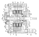
この発明の第1の実施形態にかかる冷却構造が適用されたモータの断面図である。
(A)は同モータのスペーサの正面図、(B)はそのIIB-IIB断面図である。
この発明の第2の実施形態にかかる冷却構造が適用されたモータの断面図である。
(A)は同モータのスペーサの正面図、(B)はそのIVB-O-IVB’断面図である。
この発明の第1の実施形態を図1および図2と共に説明する。図1において、この冷却構造が適用されたモータは、ステータ1とロータ5とでなり、それぞれのステータコア2とロータコア6間にラジアル方向のギャップ部9を設けたラジアルギャップ型のモータである。
ステータ1は、環状に配置された複数の前記ステータコア2と、このステータコア2の径方向を向く中心軸、つまりロータ5の軸心と直交する方向に延びる中心軸周りに巻かれたステータコイル3と、これらステータコア2およびステータコイル3を収容するステータハウジング4とで構成される。ステータコア2は、複数枚の鋼板2aを軸方向に積層状に並べた積層鋼板からなり、ステータハウジング4の内周面に固定されている。ステータコイル3の軸方向一端には、ステータハウジング4の外部に繋がるコイル引出し部3aが設けられている。
ロータ5は、前記ステータコア2の内周側に配置されたものであり、永久磁石からなる環状の前記ロータコア6と、ロータ5の中心に位置するロータ回転軸7と、これらロータコア6とロータ回転軸7間に介在して両者を一体に回転するように結合するコア支持体部としての筒状のロータスピンドル8とで構成される。
ロータ回転軸7は、一対の軸受11によりステータハウジング4の両側側板部4a,4bに対し回転自在に支持されている。ロータ回転軸7は軸方向中間部に拡径部7aを有し、この拡径部7aの一端面(図1では右側面)にロータスピンドル8の他端面(図1では左側面)を接触させた状態で、ロータ回転軸7の外周にロータスピンドル8が設けられている。ロータ回転軸7とロータスピンドル8とは、例えば圧入により互いに固定されている。この実施形態のように、ロータ回転軸7とコア支持体部としてのロータスピンドル8とを別体とせずに、ロータ回転軸7と一体のコア支持体部(図示せず)を設けてもよいが、ロータ回転軸7とコア支持体部とを別体にした方が両者の加工が容易である。
ロータスピンドル8は、軸方向両側に延びるフランジ部8aを有し、このフランジ部8aの軸方向両端に外径側に延びる第1および第2のつば部8b,8cが設けられている。一端側の第1つば部8bはフランジ部8aと一体に形成され、他端側の第2つば部8cはフランジ部8aと別の部材をボルト12でフランジ部8aに固定することで形成してある。そして、これら第1および第2のつば部8b,8c間のフランジ部8aの外周面に、ロータコア6が圧入により固定状態に取付けられている。
ロータコア6は、複数枚の円環状の鋼板6aを軸方向に積層状に並べた積層鋼板からなり、一部の隣合う鋼板6a間に隙間13が設けられている。この例では、軸方向の2箇所に隙間13が設けられているが、隙間13は1箇所であっても、3箇所以上であってもよい。隙間13は、鋼板6a間の内径端付近に、図2(A)に示すスペーサ14を介在させることで形成されている。スペーサ14は所定幅の円環状の部材であり、図2(B)に示すように、周方向の複数箇所に内径側と外径側とを連通する導油孔15が設けられている。この導油孔15の外径端は、図2(B)の部分拡大図に示すように、外径側ほど拡径したテーパ部15aとされている。
また、図1のロータコア6の端面とロータスピンドル8の第1および第2のつば部8b,8cとの間にそれぞれ冷却路形成部材16が介在されており、この冷却路形成部材16に、ロータコア6側に開口して径方向に延びる溝状のロータ端面冷却路17,18がそれぞれ複数本ずつ設けられている。一方のロータ端面冷却路17は、中間部よりも外径側の部分17aがロータコア6の端面から離れて軸方向外側へ延び、その先端が冷却路形成部材16の外側面に開口している。もう一方のロータ端面冷却路18は、内径端から外径端にわたってロータコア6の端面に沿って設けられ、外径端は冷却路形成部材16の外周面に面している。これらロータ端面冷却路17,18は、交互に周方向等間隔で設けられている。
ロータ回転軸7の軸芯部には、一端が開口し軸方向に延びる冷却油用の給油路21が設けられている。給油路21は、ロータコア6の軸方向の中心よりも他端側まで延び、その先端はロータスピンドル8のロータ回転軸7に嵌合する部分の側面と略同じ位置とされている。給油路21は、内径が比較的大きめで、例えばロータ回転軸7の外径の1/3~1/2程度以上とされ、ロータ回転軸7内に中空状の空間を形成している。そして、この給油路21の閉塞側の端部付近からロータスピンドル8の外周にわたって、つまり給油路21に臨む内径端からロータスピンドル8の外周面に開口する外径端まで径方向に延びる連通孔22が、周方向に複数設けられている。また、ロータスピンドル8の外周面には、連通孔22の外径端に繋がる軸方向に延びる連通溝23が形成されている。これら連通孔22および連通溝23で、給油路21と前記隙間13およびロータ端面冷却路17,18とを連通する連通路24を構成している。
給油路21の開口端は、外部から冷却油を供給するための冷却油供給路25の出口に隣接して非接触で対向して連通している。冷却油供給路25は、ステータハウジング4に取付けられた供給路形成部材26に形成されている。供給路形成部材26は、ロータ回転軸7が嵌まる軸端進入凹部26aを有し、この軸端進入凹部26aとロータ回転軸7の外周面との間でラビリンスシールを構成している。ラビリンスシールは一端側の軸受の外側に形成されている。ロータ回転軸7の他端における軸受11の外側は、オイルシール等の接触式のシール27により密封されている。また、ステータハウジング4の下部には冷却油排出口28が設けられ、この冷却油排出口28に冷却油排出路29が接続されている。冷却油排出路29は冷却油供給装置(図示せず)を経由して前記冷却油供給路25に繋がっている。冷却油供給装置は、冷却装置、ポンプ、フィルタ等を組み合わせたものである。
このモータの冷却構造によると、外部から圧送されてくる冷却油30が、ロータ回転軸7内の給油路21に供給され、軸芯冷却を行う。給油路21は内径が比較的大きく、多量の冷却油30が滞留するため、ロータ回転軸7の回転抵抗により発生した熱を効果的に奪うことができる。給油路21内の冷却油30は、連通孔22および連通溝23からなる連通路24を通って、一部はスペーサ14の導油孔15からロータコア6の隙間13内に浸入し、残りはロータ端面冷却路17,18に流れ込む。導油孔15の外径端は外径側ほど拡径したテーパ部15aになっているため、導油孔15から吐出される冷却油30は隙間13内に広く拡散する。冷却油30が隙間13内に滞在する間に、ロータコア6の軸方向中央部の熱を奪う。また、ロータ端面冷却路17,18を流れる冷却油30により、ロータコア6の端面付近の熱を奪う。
隙間13内に浸入した冷却油30は、ロータ5の回転による遠心力で外径側へ飛ばされ、ステータコア2およびステータコイル3の内周面に当たる。それにより、ステータコイル3で発生した熱、およびステータコイル3から伝達されたステータコア2の熱を奪う。また、ロータ端面冷却路17,18から流出した冷却油30も、ステータコイル3の軸方向両端部に当たり、ステータコイル3で発生した熱を奪う。ロータ端面冷却路17からの冷却油30の流出方向を斜め外向きとすることで、冷却油30を広い範囲に拡散させることができ、ステータコイル3の軸方向両端部の冷却効果が高い。
このように、冷却油30により、ロータ5およびステータ1の各部の熱を効率良く奪うので、モータ内部の冷却効果が高い。それにより、ステータコイル3の発熱等によるモータ内部の温度上昇を抑えて、モータの破損を回避することができる。このため、小型高出力のモータに効果的である。
遠心力でステータコイル3まで飛ばされた冷却油30は、その後、重力により落下してステータハウジング4の内部空間の下方に溜まる。そして、冷却油排出口28から冷却油排出路29を通って、冷却油供給装置に戻される。
図3および図4は、この発明の第2の実施形態を示す。この実施形態のモータの冷却構造が前記実施形態のものと異なる点は、ロータコア6の鋼板6a間に隙間13を設けるためのスペーサにある。図4(A)に示すように、この実施形態のスペーサ34は、概略形状が環状の円板で、図4(B)に示すように、冷却油30(図3)を内径側から外径側へ導く導油用切欠き35が両側面に複数ずつ設けられている。導油用切欠き35の外径端は、外径側ほど拡径したテーパ状部35aとされている。このスペーサ34は、図3の隙間13の内径端から外径端にわたって設けられている。他は、第1の実施形態と同じ構成である。
このモータの冷却構造の場合、連通路24を流れる冷却油30の一部が、ロータコア6の隙間13内に設けられたスペーサ34の導油用切欠き35(図4(A))を通って、ロータコア6の外周面に吐出する。導油用切欠き35は鋼板6aに面しているため、冷却油30が導油用切欠き35を通る際に、ロータコア6の軸方向中央部の熱を奪う。導油用切欠き35の外径端は外径側ほど拡径したテーパ部35aになっているため、導油用切欠き35から吐出される冷却油30は広く拡散して、ステータコア2およびステータコイル3の内周面に当たる。それにより、ステータコア2およびステータコイル3で発生した熱を奪う。他の冷却油30の流れは前記同様であり、同様の作用および効果が得られる。
以上のとおり、図面を参照しながら本発明の好適な実施形態を説明したが、本発明の趣旨を逸脱しない範囲内で、種々の追加、変更または削除が可能である。したがって、そのようなものも本発明の範囲内に含まれる。
1…ステータ
2…ステータコア
3…ステータコイル
4…ステータハウジング
5…ロータ
6…ロータコア
6a…鋼板
7…ロータ回転軸
8…ロータスピンドル(コア支持体部)
13…隙間
14,34…スペーサ
15…導油路
15a…テーパ部
17,18…ロータ端面冷却路
21…給油路
22…連通孔
23…連通溝
24…連通路
25…冷却油供給路
26…供給路形成部材
28…冷却油排出口
30…冷却油
35…導油用切欠き
35a…テーパ部
2…ステータコア
3…ステータコイル
4…ステータハウジング
5…ロータ
6…ロータコア
6a…鋼板
7…ロータ回転軸
8…ロータスピンドル(コア支持体部)
13…隙間
14,34…スペーサ
15…導油路
15a…テーパ部
17,18…ロータ端面冷却路
21…給油路
22…連通孔
23…連通溝
24…連通路
25…冷却油供給路
26…供給路形成部材
28…冷却油排出口
30…冷却油
35…導油用切欠き
35a…テーパ部
Claims (11)
- ステータコイル、および環状に配列または形成されたステータコアを有するステータと、前記ステータコアの内周側に位置して前記ステータに対し回転自在となるロータとでなるモータであって、前記ロータは、ロータ回転軸の外周にコア支持体部を介してロータコアを取付けてなり、前記ロータコアは複数枚の鋼板を軸方向に積層状に並べたものであり、一部の隣合う鋼板間に隙間を設け、前記ロータ回転軸の内部に軸方向に延びる冷却油用の給油路を設け、この給油路と前記隙間とを連通する連通路を、前記ロータ回転軸に前記コア支持体部にわたって設けているモータの冷却構造。
- 請求項1において、前記ロータコアの前記鋼板間の隙間が軸方向の複数箇所に設けられたモータの冷却構造。
- 請求項1において、前記コア支持体部は、前記ロータ回転軸の外周に設けた筒状のロータスピンドルであるモータの冷却構造。
- 請求項1において、前記連通路に連通して、前記冷却油を前記ロータコアの端面に導くロータ端面冷却路を設けたモータの冷却構造。
- 請求項1において、隣合う鋼板間に、前記冷却油を内径側から外径側へ導く導油孔を内部に有する環状のスペーサを介在させることで、前記ロータコアの隙間を設けたモータの冷却構造。
- 請求項5において、前記導油孔の外径端を、外径側ほど拡径したテーパ状に形成したモータの冷却構造。
- 請求項1において、隣合う鋼板間に、前記冷却油を内径側から外径側へ導く導油用切欠きを外側面に有する環状のスペーサを介在させることで、前記ロータコアの隙間を設けたモータの冷却構造。
- 請求項7において、前記導油用切欠きの外径端を、外径側ほど拡径したテーパ状に形成したモータの冷却構造。
- 請求項1において、前記ステータを収容するステータハウジングを有し、このステータハウジングに、外部から前記ロータ回転軸の前記給油路に冷却油を供給する冷却油供給路を有する供給路形成部材を取付けたモータの冷却構造。
- 請求項1において、前記ステータを収容するステータハウジングを有し、このステータハウジングの下部に、前記冷却油を外部に排出する冷却油排出口を設けたモータの冷却構造。
- 請求項1に記載の冷却構造を備えたモータ。
Applications Claiming Priority (2)
| Application Number | Priority Date | Filing Date | Title |
|---|---|---|---|
| JP2009112609A JP5448559B2 (ja) | 2009-05-07 | 2009-05-07 | モータの冷却構造 |
| JP2009-112609 | 2009-05-07 |
Publications (1)
| Publication Number | Publication Date |
|---|---|
| WO2010128632A1 true WO2010128632A1 (ja) | 2010-11-11 |
Family
ID=43050133
Family Applications (1)
| Application Number | Title | Priority Date | Filing Date |
|---|---|---|---|
| PCT/JP2010/057398 Ceased WO2010128632A1 (ja) | 2009-05-07 | 2010-04-27 | モータの冷却構造 |
Country Status (2)
| Country | Link |
|---|---|
| JP (1) | JP5448559B2 (ja) |
| WO (1) | WO2010128632A1 (ja) |
Cited By (18)
| Publication number | Priority date | Publication date | Assignee | Title |
|---|---|---|---|---|
| CN103248157A (zh) * | 2012-02-14 | 2013-08-14 | 通用汽车环球科技运作有限责任公司 | 转子冷却结构 |
| WO2015151589A1 (ja) * | 2014-04-02 | 2015-10-08 | 株式会社豊田自動織機 | ロータ |
| WO2018033388A1 (de) * | 2016-08-17 | 2018-02-22 | Bayerische Motoren Werke Aktiengesellschaft | Elektrische maschine und fahrzeug mit der elektrischen maschine |
| EP2765684A3 (en) * | 2013-02-08 | 2018-03-28 | Hitachi, Ltd. | Rotating electrical machine |
| CN108880042A (zh) * | 2018-09-10 | 2018-11-23 | 华域汽车电动系统有限公司 | 一种电机转子冷却油路结构 |
| CN110707843A (zh) * | 2019-08-09 | 2020-01-17 | 武汉理工大学 | 电机冷却结构及电动汽车用永磁同步电机 |
| CN111033969A (zh) * | 2017-08-25 | 2020-04-17 | 日本电产株式会社 | 驱动装置 |
| JP2020108199A (ja) * | 2018-12-26 | 2020-07-09 | トヨタ自動車株式会社 | ステータおよびモータ |
| CN111969790A (zh) * | 2020-07-30 | 2020-11-20 | 南京师范大学 | 一种油冷电机的冷却系统 |
| CN112311152A (zh) * | 2019-07-31 | 2021-02-02 | 华擎机械工业股份有限公司 | 具有内部冷却机制的电机机械装置 |
| CN114069969A (zh) * | 2020-08-03 | 2022-02-18 | 安徽威灵汽车部件有限公司 | 电机和车辆 |
| DE102021101937A1 (de) | 2021-01-28 | 2022-07-28 | Rolls-Royce Deutschland Ltd & Co Kg | Elektrische Maschine und Verfahren zur Reinigung eines Luftspalts in einer elektrischen Maschine |
| CN115347729A (zh) * | 2021-05-12 | 2022-11-15 | 上汽通用汽车有限公司 | 动平衡板、电机及车辆 |
| CN115441630A (zh) * | 2021-06-02 | 2022-12-06 | 上汽通用汽车有限公司 | 密封垫片、电机及车辆 |
| US12191752B2 (en) | 2020-08-03 | 2025-01-07 | Anhui Welling Auto Parts Co., Ltd. | Motor and vehicle |
| US20250096648A1 (en) * | 2023-09-19 | 2025-03-20 | Subaru Corporation | Motor-cooling structure |
| FR3154948A1 (fr) * | 2023-11-06 | 2025-05-09 | Renault S.A.S | Agencement pour véhicule automobile à motorisation électrique ou hybride et moteur électrique pour un tel agencement |
| CN120915027A (zh) * | 2025-08-07 | 2025-11-07 | 东营合瑞石油技术有限责任公司 | 一种节能永磁同步电动机 |
Families Citing this family (12)
| Publication number | Priority date | Publication date | Assignee | Title |
|---|---|---|---|---|
| JP5060630B1 (ja) * | 2011-03-31 | 2012-10-31 | 株式会社小松製作所 | 発電電動機の冷却構造及び発電電動機 |
| JP5899716B2 (ja) * | 2011-09-02 | 2016-04-06 | トヨタ自動車株式会社 | 回転電機のロータ構造 |
| JP5772415B2 (ja) * | 2011-09-08 | 2015-09-02 | トヨタ自動車株式会社 | 回転電機のロータ構造 |
| JP6268750B2 (ja) * | 2013-05-23 | 2018-01-31 | トヨタ自動車株式会社 | 回転電機 |
| JP2015064058A (ja) * | 2013-09-25 | 2015-04-09 | ジヤトコ株式会社 | マルチディスク変速機 |
| DE102016216685A1 (de) * | 2016-09-02 | 2018-03-08 | Continental Automotive Gmbh | Rotor für eine elektrische Maschine |
| JP6864494B2 (ja) * | 2017-02-23 | 2021-04-28 | 東芝産業機器システム株式会社 | 治具、電動機の製造方法 |
| JP2019149884A (ja) * | 2018-02-27 | 2019-09-05 | 本田技研工業株式会社 | 回転電機のロータ、及び、回転電機 |
| DE102018215734A1 (de) * | 2018-09-17 | 2020-03-19 | Conti Temic Microelectronic Gmbh | Baukastensystem zum Herstellen von unterschiedlichen Bauvarianten eines Rotors für eine elektrische Maschine eines Kraftfahrzeugs sowie elektrische Maschine für ein Kraftfahrzeug |
| DE102019202566A1 (de) * | 2019-02-26 | 2020-08-27 | Zf Friedrichshafen Ag | Rotor für eine elektrische Maschine mit Kühlkanälen |
| CN116491055A (zh) * | 2020-11-19 | 2023-07-25 | 尼得科株式会社 | 旋转电机及驱动装置 |
| DE102020216237A1 (de) | 2020-12-18 | 2022-06-23 | Zf Friedrichshafen Ag | Rotor und elektrische Maschine mit einem solchen Rotor |
Citations (9)
| Publication number | Priority date | Publication date | Assignee | Title |
|---|---|---|---|---|
| JPS56139367U (ja) * | 1980-03-19 | 1981-10-21 | ||
| JPS5789370U (ja) * | 1980-11-19 | 1982-06-02 | ||
| JPH09154258A (ja) * | 1995-11-29 | 1997-06-10 | Mitsubishi Heavy Ind Ltd | 強制油冷式電動機又は発電機の冷却構造 |
| JPH11206063A (ja) * | 1997-12-26 | 1999-07-30 | Toyota Motor Corp | 電動機および動力伝達装置並びにその製造方法 |
| JP2003324901A (ja) * | 2002-04-26 | 2003-11-14 | Nippon Soken Inc | 電動機 |
| JP2004282902A (ja) * | 2003-03-14 | 2004-10-07 | Toyota Motor Corp | 回転電機 |
| JP2005006429A (ja) * | 2003-06-12 | 2005-01-06 | Toyota Motor Corp | 回転電機におけるロータ構造 |
| JP2006067777A (ja) * | 2004-07-30 | 2006-03-09 | Honda Motor Co Ltd | 回転電機の冷却構造 |
| JP2009055737A (ja) * | 2007-08-28 | 2009-03-12 | Toyota Motor Corp | ロータおよび回転電機 |
-
2009
- 2009-05-07 JP JP2009112609A patent/JP5448559B2/ja not_active Expired - Fee Related
-
2010
- 2010-04-27 WO PCT/JP2010/057398 patent/WO2010128632A1/ja not_active Ceased
Patent Citations (9)
| Publication number | Priority date | Publication date | Assignee | Title |
|---|---|---|---|---|
| JPS56139367U (ja) * | 1980-03-19 | 1981-10-21 | ||
| JPS5789370U (ja) * | 1980-11-19 | 1982-06-02 | ||
| JPH09154258A (ja) * | 1995-11-29 | 1997-06-10 | Mitsubishi Heavy Ind Ltd | 強制油冷式電動機又は発電機の冷却構造 |
| JPH11206063A (ja) * | 1997-12-26 | 1999-07-30 | Toyota Motor Corp | 電動機および動力伝達装置並びにその製造方法 |
| JP2003324901A (ja) * | 2002-04-26 | 2003-11-14 | Nippon Soken Inc | 電動機 |
| JP2004282902A (ja) * | 2003-03-14 | 2004-10-07 | Toyota Motor Corp | 回転電機 |
| JP2005006429A (ja) * | 2003-06-12 | 2005-01-06 | Toyota Motor Corp | 回転電機におけるロータ構造 |
| JP2006067777A (ja) * | 2004-07-30 | 2006-03-09 | Honda Motor Co Ltd | 回転電機の冷却構造 |
| JP2009055737A (ja) * | 2007-08-28 | 2009-03-12 | Toyota Motor Corp | ロータおよび回転電機 |
Cited By (22)
| Publication number | Priority date | Publication date | Assignee | Title |
|---|---|---|---|---|
| US9203284B2 (en) | 2012-02-14 | 2015-12-01 | GM Global Technology Operations LLC | Rotor cooling structures |
| CN103248157A (zh) * | 2012-02-14 | 2013-08-14 | 通用汽车环球科技运作有限责任公司 | 转子冷却结构 |
| EP2765684A3 (en) * | 2013-02-08 | 2018-03-28 | Hitachi, Ltd. | Rotating electrical machine |
| WO2015151589A1 (ja) * | 2014-04-02 | 2015-10-08 | 株式会社豊田自動織機 | ロータ |
| WO2018033388A1 (de) * | 2016-08-17 | 2018-02-22 | Bayerische Motoren Werke Aktiengesellschaft | Elektrische maschine und fahrzeug mit der elektrischen maschine |
| US10680478B2 (en) | 2016-08-17 | 2020-06-09 | Bayerische Motoren Werke Aktiengesellschaft | Electrical machine and vehicle equipped with the electrical machine |
| CN111033969A (zh) * | 2017-08-25 | 2020-04-17 | 日本电产株式会社 | 驱动装置 |
| CN108880042A (zh) * | 2018-09-10 | 2018-11-23 | 华域汽车电动系统有限公司 | 一种电机转子冷却油路结构 |
| JP7192488B2 (ja) | 2018-12-26 | 2022-12-20 | トヨタ自動車株式会社 | モータ |
| JP2020108199A (ja) * | 2018-12-26 | 2020-07-09 | トヨタ自動車株式会社 | ステータおよびモータ |
| CN112311152A (zh) * | 2019-07-31 | 2021-02-02 | 华擎机械工业股份有限公司 | 具有内部冷却机制的电机机械装置 |
| CN110707843A (zh) * | 2019-08-09 | 2020-01-17 | 武汉理工大学 | 电机冷却结构及电动汽车用永磁同步电机 |
| CN111969790A (zh) * | 2020-07-30 | 2020-11-20 | 南京师范大学 | 一种油冷电机的冷却系统 |
| CN114069969A (zh) * | 2020-08-03 | 2022-02-18 | 安徽威灵汽车部件有限公司 | 电机和车辆 |
| US12191752B2 (en) | 2020-08-03 | 2025-01-07 | Anhui Welling Auto Parts Co., Ltd. | Motor and vehicle |
| DE102021101937A1 (de) | 2021-01-28 | 2022-07-28 | Rolls-Royce Deutschland Ltd & Co Kg | Elektrische Maschine und Verfahren zur Reinigung eines Luftspalts in einer elektrischen Maschine |
| CN115347729A (zh) * | 2021-05-12 | 2022-11-15 | 上汽通用汽车有限公司 | 动平衡板、电机及车辆 |
| CN115441630A (zh) * | 2021-06-02 | 2022-12-06 | 上汽通用汽车有限公司 | 密封垫片、电机及车辆 |
| US20250096648A1 (en) * | 2023-09-19 | 2025-03-20 | Subaru Corporation | Motor-cooling structure |
| FR3154948A1 (fr) * | 2023-11-06 | 2025-05-09 | Renault S.A.S | Agencement pour véhicule automobile à motorisation électrique ou hybride et moteur électrique pour un tel agencement |
| WO2025099087A1 (fr) * | 2023-11-06 | 2025-05-15 | Horse Powertrain Solutions, S.L.U | Agencement pour véhicule automobile à motorisation électrique ou hybride et moteur électrique pour un tel agencement |
| CN120915027A (zh) * | 2025-08-07 | 2025-11-07 | 东营合瑞石油技术有限责任公司 | 一种节能永磁同步电动机 |
Also Published As
| Publication number | Publication date |
|---|---|
| JP2010263696A (ja) | 2010-11-18 |
| JP5448559B2 (ja) | 2014-03-19 |
Similar Documents
| Publication | Publication Date | Title |
|---|---|---|
| WO2010128632A1 (ja) | モータの冷却構造 | |
| JP4450050B2 (ja) | モータの冷却構造 | |
| JP2006067777A (ja) | 回転電機の冷却構造 | |
| CN108886281A (zh) | 电机的转子部分 | |
| JP5765149B2 (ja) | 回転電機 | |
| JP2012105487A (ja) | 電動モータの冷却装置 | |
| JP2016146704A (ja) | 回転電機 | |
| US20140097711A1 (en) | One piece rotor hub/shaft for an electric machine and method | |
| JP6378285B2 (ja) | エアパージの機能を有する電動機 | |
| CN106166687A (zh) | 主轴构造、电动机、以及机床 | |
| US10001170B2 (en) | Rolling bearing | |
| WO2020262093A1 (ja) | モータ | |
| JP2015089316A (ja) | 回転電機 | |
| WO2019188621A1 (ja) | 軸受装置の冷却構造 | |
| JP5065166B2 (ja) | 回転電機の回転子 | |
| CN102959837B (zh) | 旋转电机的冷却构造 | |
| JP5710886B2 (ja) | 回転電機 | |
| JP7164962B2 (ja) | 軸受装置の冷却構造 | |
| JP2019173908A (ja) | 軸受装置の冷却構造 | |
| JP5013751B2 (ja) | 電動機 | |
| JP6272526B1 (ja) | 回転電機 | |
| JP6629064B2 (ja) | 巻上機 | |
| CN220172946U (zh) | 电机、电动总成和车辆 | |
| JP2022070634A (ja) | 回転電機用ロータ | |
| US10284048B2 (en) | Electric motor for suppressing entry of foreign substances |
Legal Events
| Date | Code | Title | Description |
|---|---|---|---|
| 121 | Ep: the epo has been informed by wipo that ep was designated in this application |
Ref document number: 10772151 Country of ref document: EP Kind code of ref document: A1 |
|
| NENP | Non-entry into the national phase |
Ref country code: DE |
|
| 122 | Ep: pct application non-entry in european phase |
Ref document number: 10772151 Country of ref document: EP Kind code of ref document: A1 |