WO2010120158A2 - 전기도금 장치 - Google Patents
전기도금 장치 Download PDFInfo
- Publication number
- WO2010120158A2 WO2010120158A2 PCT/KR2010/002425 KR2010002425W WO2010120158A2 WO 2010120158 A2 WO2010120158 A2 WO 2010120158A2 KR 2010002425 W KR2010002425 W KR 2010002425W WO 2010120158 A2 WO2010120158 A2 WO 2010120158A2
- Authority
- WO
- WIPO (PCT)
- Prior art keywords
- electrolyte
- supply unit
- plated
- plated body
- plating
- Prior art date
- Legal status (The legal status is an assumption and is not a legal conclusion. Google has not performed a legal analysis and makes no representation as to the accuracy of the status listed.)
- Ceased
Links
Images



Classifications
-
- C—CHEMISTRY; METALLURGY
- C25—ELECTROLYTIC OR ELECTROPHORETIC PROCESSES; APPARATUS THEREFOR
- C25D—PROCESSES FOR THE ELECTROLYTIC OR ELECTROPHORETIC PRODUCTION OF COATINGS; ELECTROFORMING; APPARATUS THEREFOR
- C25D5/00—Electroplating characterised by the process; Pretreatment or after-treatment of workpieces
- C25D5/08—Electroplating with moving electrolyte e.g. jet electroplating
-
- C—CHEMISTRY; METALLURGY
- C25—ELECTROLYTIC OR ELECTROPHORETIC PROCESSES; APPARATUS THEREFOR
- C25D—PROCESSES FOR THE ELECTROLYTIC OR ELECTROPHORETIC PRODUCTION OF COATINGS; ELECTROFORMING; APPARATUS THEREFOR
- C25D17/00—Constructional parts, or assemblies thereof, of cells for electrolytic coating
- C25D17/02—Tanks; Installations therefor
-
- C—CHEMISTRY; METALLURGY
- C25—ELECTROLYTIC OR ELECTROPHORETIC PROCESSES; APPARATUS THEREFOR
- C25D—PROCESSES FOR THE ELECTROLYTIC OR ELECTROPHORETIC PRODUCTION OF COATINGS; ELECTROFORMING; APPARATUS THEREFOR
- C25D17/00—Constructional parts, or assemblies thereof, of cells for electrolytic coating
- C25D17/02—Tanks; Installations therefor
- C25D17/04—External supporting frames or structures
Definitions
- the present invention relates to a plating apparatus, and more particularly, to an electroplating apparatus.
- electroplating sometimes serves both industrial application such as decorative beautification, anticorrosion and abrasion resistance, contact resistance improvement, carburization prevention, and the like.
- the general process of electroplating is the order of dehydration ⁇ polishing ⁇ degreasing ⁇ chemical dipping treatment ⁇ electroplating ⁇ post treatment ⁇ drying.
- FIG. 1 is a view showing a general electroplating apparatus.
- the plated body 120 is connected to a negative electrode ( ⁇ ), and connects a positive electrode (+) to a metal plate 130 made of a material of an electrode to be electrodeposited.
- the plated body 120 and the metal plate 130 are placed in the electrolyte solution 110 containing the ions of the metal to be electrodeposited, so that the desired metal ions are applied to the surface of the plated body 120 by energizing and electrolyzing. do.
- the electrolyte 110 is accommodated in the plating bath 100. Electroplating as described above is a type of wet plating.
- the inner space or the receiving portion of the plated body is not well plated, so that the plating layer is thinly formed. have.
- the inner plating thickness layer is set to 5 mu m
- the outer plating thickness layer is formed to about 7.5 to 8 mu m.
- an object of the present invention is to provide an electroplating apparatus using a spray method.
- Another object of the present invention is to provide an apparatus for uniformly electroplating concave portions of a plated body having various forms.
- Still another object of the present invention is to provide an electroplating apparatus capable of minimizing time required for plating and manufacturing cost.
- the plating bath containing the electrolyte solution, and the electrolyte containing the metal ions connected to the plating bath to be electrodeposited to a specific portion of the plated body is injected And a supply part, wherein the supply part is connected to the positive electrode, and the plated body is connected to the negative electrode.
- the present invention is advantageous in that uniform plating and selective plating are possible by plating only desired portions of a plated body having various shapes using a spraying method.
- a plating bath having a small size and a small amount of electrolyte compared to the conventional plating bath has the advantage that can significantly reduce the material cost, there is an advantage that can be improved faster than the conventional plating speed.
- FIG. 1 is a view showing a general electroplating apparatus
- FIG. 2 is a view showing an electroplating apparatus according to a first embodiment of the present invention
- FIG. 3 is a flowchart illustrating a plating process according to the first embodiment of the present invention.
- FIG. 4 is a view showing an electroplating apparatus according to a second embodiment of the present invention.
- FIG. 5 is a view showing an electroplating apparatus according to a fifth embodiment of the present invention.
- FIG. 6 is a view showing an electroplating apparatus according to a sixth embodiment of the present invention.
- FIG. 7 is a perspective view of an electrolyte supply unit provided in an electroplating apparatus according to a sixth embodiment of the present invention.
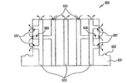
- Figure 8 is a side cross-sectional view of the auxiliary anode body provided in the electroplating apparatus according to the sixth embodiment of the present invention.
- the present invention proposes an electroplating apparatus capable of plating uniformly and quickly the portion to be plated in a plated body having various forms by using at least one plating method of the wet plating method and the spray plating method.
- FIG. 2 is a view showing an electroplating apparatus according to a first embodiment of the present invention.
- the electroplating apparatus includes a plating bath 200, a supply unit 220, and a pipe 230 connected to the supply unit 220.
- the plated body 240 to be plated may be positioned above the supply unit 220, and the plating bath 200 may contain an electrolyte solution containing ions of metals to be electrodeposited onto the plated body 240. 210 is filled in a certain amount.
- the tube 230 may be composed of at least one, and a plurality of injection holes exist in a specific portion of the supply unit 220, the plurality of injection holes are a plurality of injection holes containing the metal ions to be electrodeposited It performs a function that can be sprayed on the plated body (240).
- the plurality of injection holes should be formed to satisfy any one or more of size, inclination angle and length so that the plated body 240 is uniformly plated.
- at least one drain hole may be formed to allow the injected electrolyte 210 to flow back into the plating tank 200.
- the supply unit 220 has a positive electrode (+) is connected, the plated body 240 is a negative electrode (-) is connected.
- the electrolyte 210 is supplied through the pipe 230 by using a power of a motor or a pump (not shown). 220 is reached.
- the metal ions of the electrolyte solution injected through the supply unit 220 adhere to the surface of the concave portion of the plated body 240.
- the electrolyte injected through the supply unit 220 includes a kind of electrolyzed metal ions, and the metal ions of the anode are plated on the concave portion of the plated body 240 of the cathode.
- Shapes of the supply unit 220 and the injection hole may be variously formed in accordance with the shape of the plated body 240, the size of the plating bath 200 can be formed very small compared to the prior art.
- the plated body 240 may preferably be an RF filter, and in addition, the plated body 240 may be made of various materials such as plastic and magnesium.
- the supply part 220 may rotate, and when the supply part 220 rotates, more uniform plating may be performed on the plated body 240.
- the supply unit 220 may be positioned separately from the side surface of the plating bath 200 or the plating bath 200. . When the supply part 220 is located separately from the plating bath 200, the supply part 220 and the plating bath 200 may be connected to a pipe through which the electrolyte 210 is transported.
- FIG. 3 is a flowchart illustrating a plating process according to the first embodiment of the present invention.
- a negative electrode is connected to a plated body, and a positive electrode is connected to a supply unit or an electrolyte, and then power is applied to the electroplating apparatus.
- an electrolyte solution containing metal ions to be electrodeposited through the supply unit is sprayed onto the object to be plated.
- the injected electrolyte is electrodeposited onto the plated body having the negative electrode, and the plated body is plated.
- FIG. 4 is a view showing an electroplating apparatus according to a second embodiment of the present invention.
- the electroplating apparatus may attach and detach the auxiliary anode body 430 having a plurality of injection holes formed outside the supply unit 420.
- the auxiliary anode body 430 is connected to the anode, so that the injected electrolyte may be more uniformly electrodeposited on the plated body 410.
- the auxiliary anode body 430 may be variously modified according to the shape or volume of the plated body 410, and may be omitted from components of the electroplating apparatus according to the second embodiment of the present invention as necessary. Can be.
- the plated body 410 is covered on one side of the supply unit 420 in which the auxiliary anode body 430 does not exist or the outside of the auxiliary anode body 430, the plated body 410 and the A rubber packing may be formed on the contact surface where the supply part 420 meets.
- the rubber packing functions to prevent the to-be-plated body 410 from being shaken during the electrodeposition process and to prevent the electrolyte solution filled inside the to-be-plated body 410 from being discharged to the outside of the to-be-plated body 410. Do this.
- the supply unit 420 has a plurality of injection holes 425 so that the electrolyte is injected to the plating target portion.
- the circulation pump 415 is operated to pump the electrolyte solution contained in the plating bath.
- the pumped electrolyte is injected through the supply part 420, and after a predetermined time, a continuous circulation of the electrolyte occurs at the plating target portion of the plated body 410.
- the plating process according to the second embodiment of the present invention has the order of injection ⁇ power application ⁇ electrodeposition according to the pumping of the electrolyte.
- the present invention is not limited to the plating process as described above, the plating process may also proceed in the order of power ⁇ injection ⁇ electrodeposition according to the pumping of the electrolyte.
- an impurity removal filter 435 may be installed at an intermediate portion where the circulation pump 415 and the plating bath are connected.
- an auxiliary tank (not shown) for receiving the auxiliary electrolyte It may be further provided.
- the electroplating apparatus there is a portion to which the plated body can be attached and detached on one side of the plating bath, and at least one vortex for vortexing the electrolyte solution inside or outside the plating bath.
- the apparatus may further be provided.
- the vortex apparatus can generate vortices by exhaling air or by repetitive movement of mechanical shapes.
- the electroplating apparatus according to the third embodiment of the present invention has the following differences compared with the electroplating apparatus according to the first and second embodiments of the present invention.
- any one or more of a supply part and an auxiliary anode body exist inside the plated body, but in the electroplating apparatus according to the third embodiment of the present invention, The difference is that only the electrolyte is circulated inside the object to be plated.
- At least one auxiliary anode may be present inside the plated body, and at least one vortex for circulating the electrolyte in the plating bath inside or outside the plating bath.
- a device may be provided.
- FIG. 5 is a view showing an electroplating apparatus according to a fifth embodiment of the present invention.
- the electroplating apparatus may attach and detach a plurality of auxiliary anodes 530 having a plurality of injection holes formed outside the supply unit 520.
- the auxiliary positive electrode 530 is connected to the positive electrode, so that the injected electrolyte may be more uniformly electrodeposited on the plated body 510.
- the auxiliary anode body 530 may be variously modified according to the shape or volume of the plated body 510, and may be omitted from components of the electroplating apparatus according to the fifth embodiment of the present invention as necessary. Can be.
- the A rubber packing is formed on the contact surface where the plated body 510 and the supply unit 520 meet.
- the rubber packing functions to prevent the to-be-plated body 510 from being shaken during the electrodeposition process and to prevent the electrolyte solution filled inside the to-be-plated body 510 from being discharged to the outside of the to-be-plated body 510. Do this.
- the supply unit 520 has a plurality of injection holes 525 so that the electrolyte is injected to the plating target portion.
- the circulation pump 515 is operated to pump the electrolyte solution contained in the plating bath.
- the pumped electrolyte is injected through the supply unit 520, and after a predetermined time, a constant circulation of the electrolyte occurs at the plating target portion of the plated body 510.
- the plating process according to the fifth embodiment of the present invention has the order of injection ⁇ power application ⁇ electrodeposition according to the pumping of the electrolyte.
- the present invention is not limited to the plating process as described above, the plating process may also proceed in the order of power ⁇ injection according to the pumping of the electrolyte ⁇ electrodeposition.
- an impurity removal filter 535 may be installed at an intermediate portion where the circulation pump 515 and the plating bath are connected.
- an auxiliary tank (not shown) for receiving the auxiliary electrolyte It may be further provided.
- the plating apparatus may uniformly plate the plated body 510 having a plurality of plating target portions at once.
- the plating speed may be determined according to the pressure.
- the pressure may be various factors, for example, the pressure at which the electrolyte is injected, the injection pressure of the circulation pump, the air pressure filled in the plating target portion, and the like.
- plating apparatus according to the first to fifth embodiments of the present invention since the circulation occurs in a state in which the electrolyte is full or quasi-full, plating is more uniform than plating in the general spray method. It becomes possible.
- the above-described first to fifth embodiments are for performing plating inside the to-be-plated body, and exemplarily injecting an electrolyte solution into the to-be-plated body in a state where the to-be-plated body is provided outside the plating bath.
- the plated body is an RF filter
- the sixth embodiment of the present invention proposes an electroplating apparatus capable of forming different thicknesses of the inside and the outside of the plated body.
- the electroplating apparatus according to the sixth embodiment of the present invention performs plating inside as well as outside of the plated body, a relatively large amount of metal ions are required for plating. Therefore, the metal ions can be used for copper plating or the like having a relatively low cost.
- FIG. 6 is a view showing an electroplating apparatus according to a sixth embodiment of the present invention.
- the electroplating apparatus includes a plating bath 601 in which an electrolyte solution 603 is accommodated.
- the plated body 610 is immersed in the electrolyte 603 of the plating bath 601,
- An electrolyte supply unit 620 for supplying an electrolyte solution to an inner portion of the plating member 610 is mounted.
- the electrolyte supply unit 620 receives an electrolyte solution at a predetermined pressure from inside or outside the plating bath, and sprays the supplied electrolyte solution toward the plated body 610.
- the auxiliary anode body 630 may be connected to the electrolyte supply unit 620 to pass the electrolyte solution from the electrolyte supply unit 620 to supply the electrolyte solution.
- the electrolyte solution from the electrolyte supply part 620 is injected into the inside of the to-be-plated body 610 through the auxiliary anode body 630.
- the metal ions eg, copper ions
- the plating layer ie, inside the plated body 610) The first plating layer
- the first plating layer is formed.
- the plating layer ie, the second plated layer outside the plated body 610 may be formed. Is formed.
- the density of the metal ions included in the electrolyte supplied to the inner side of the plated body 610 is higher than the density of the metal ions included in the electrolyte supplied to the outer side due to the auxiliary anode body 630.
- the thickness of the first plating layer may be formed relatively thicker than the thickness of the second plating layer.
- the thickness of the first plating layer may be 0.5 ⁇ m
- the thickness of the second plating layer may be 0.1 ⁇ m.
- the electroplating apparatus may further include a plated member fixing member 640 for fixing the plated body 610 is locked in the electrolyte.
- the plated member fixing member 640 includes an electrolyte supply part fixing arm 641, a plated body fixing arm 643, and a fixed arm driving part 645.
- the electrolyte supply unit fixed arm 641 is fixed so that the electrolyte supply unit 620 is fixed to the lower portion of the plated body 610, and the fixed position is controlled by the fixed arm driver 645. Accordingly, the position of the auxiliary anode body 630 connected to the upper portion of the electrolyte supply part 620 is also fixed.
- the plated body fixed arm 643 moves up and down by the fixed arm driver 645, and applies a fixing force to a portion of the upper surface of the plated body 610 mounted on the auxiliary anode body 630.
- the plated body 610 is fixed between the auxiliary anode body 630 and the plated body fixed arm 643 indirectly fixed by the electrolyte supply unit fixed arm 641.
- the fixed arm driver 645 may place the electrolyte supply unit fixed arm 641 outside the electrolyte 603 while the plated body 610 is not mounted on the auxiliary anode body 630.
- the plated body fixing arm 643 moves downward to place the plated body 610 on the top surface of the plated body 610. It is in close contact with a part and driven to apply a fixing force to the plated body 610.
- the fixed arm driver 645 is configured such that the plated body 610 is locked between the auxiliary anode body 630 and the plated body fixed arm 643 in the electrolyte solution 603 so that the electrolyte supply unit fixed arm is fixed. 641 and the plated fixed arm 643 are driven.
- the electroplating apparatus is a circulation pump for pumping the electrolyte 603 contained in the plating bath 601. 670, and may further include an impurity removal filter 650 for removing impurities contained in the electrolyte 603 during the plating process.
- the auxiliary tank 660 which accommodates the auxiliary electrolyte solution 663 as a means for maintaining the water level of the electrolyte solution 603 contained in the plating tank 601 to a predetermined water level.
- the auxiliary tank 660 may be provided between the impurity removal filter 650 and the circulation pump 670.
- the electrolyte 603 contained in the plating bath 601 is provided to the impurity removal filter 650 through the first path 605, and is again supplied to the auxiliary tank 660 through the second path 655. After being provided to the circulation pump 670 through the third path 665, it is provided to the electrolyte supply unit 620 through the fourth path 675.
- FIG. 7 is a perspective view of an electrolyte supply unit provided in the electroplating apparatus according to the sixth embodiment of the present invention.
- the electrolyte supply unit 620 includes a supply unit body 621 which simultaneously supplies an electrolyte solution supplied through the fourth path 675 through a plurality of holes, and is connected to the plurality of holes, respectively. And discharge the electrolyte supplied through the supply body 621 through a supply nozzle 625 of a predetermined length.
- FIG 8 is a side cross-sectional view of the auxiliary anode body provided in the electroplating apparatus according to the sixth embodiment of the present invention.
- the auxiliary anode body 630 includes an auxiliary anode body body 631 corresponding to the shape of the plated body 610.
- the auxiliary anode body 631 is formed with a plurality of first through holes 633 respectively provided at positions corresponding to the plurality of supply nozzles 625, and a plurality of electrolytes supplied through the supply nozzles 625 are provided.
- the first through holes 633 and 637 are discharged to the inner side of the plated body 610.
- the auxiliary anode body 631 has a second to induce the electrolyte discharged to the inner portion of the plated body 610 to be discharged to the space provided between the auxiliary anode body 630 and the electrolyte supply part 620 again.
- Through holes 635 and 639 are formed.
- metal ions (eg, copper ions) included in the auxiliary anode body 630 connected to the anode are continuously provided to the inside of the plated body 610 together with the electrolyte through the first through holes 633 and 637. do.
- the electrolyte 603 included in the plating bath 601 is supplied to the outer side of the plated body 610, and the metal ions (eg, copper ions) included in the auxiliary anode body 630 are not supplied. Accordingly, the density of the metal ions included in the electrolyte supplied to the inner side of the plated body 610 due to the auxiliary anode 630 is higher than the density of the metal ions included in the electrolyte supplied to the outer side thereof.
- the thickness of the first plating layer may be formed to be relatively thicker than the thickness of the second plating layer.
- the auxiliary anode body 631 may further include a protrusion 632 formed at a position in close contact with a portion of the plated body 610.
- the protrusion may be formed at a position corresponding to the position of the screw hole provided in the plated body 610.
- the supply unit 620 and 630 is provided with one electrolyte supply unit 620 and the auxiliary anode body 630, but the present invention is not limited thereto.
- the supply unit 620 includes one electrolyte supply unit 620 and at least one auxiliary anode 630 connected to the electrolyte supply unit 620, or a plurality of electrolyte supply units 620 and an auxiliary anode body ( 630 may be provided, of course.
Landscapes
- Chemical & Material Sciences (AREA)
- Engineering & Computer Science (AREA)
- Chemical Kinetics & Catalysis (AREA)
- Electrochemistry (AREA)
- Materials Engineering (AREA)
- Metallurgy (AREA)
- Organic Chemistry (AREA)
- Electroplating Methods And Accessories (AREA)
Abstract
본 발명은 전기도금 장치에 관한 것으로서, 전해액을 수용하는 도금조와, 상기 도금조와 연결되어 피도금체의 특정 부위에 전착시키고자 하는 금속이온을 함유한 전해액이 분사되는 공급부를 포함하며, 상기 공급부는 양극에 연결되고, 상기 피도금체는 음극에 연결됨을 특징으로 한다.
Description
본 발명은 도금 장치에 관한 것으로서, 보다 상세하게는 전기도금(electroplating) 장치에 관한 것이다.
일반적으로, 전기도금은 장식적인 미화, 방식 및 내마모성, 접촉저항의 개선, 침탄 방지 등의 공업적인 응용 및 이것들을 겸하는 경우가 있다. 도금방법과 용도에 따라 다소 차이가 있지만, 전기도금의 일반적인 공정은 탈수 → 연마 → 탈지 → 화학적 침지처리 → 전기도금 → 후처리 → 건조의 순서이다.
도 1은 일반적인 전기도금 장치를 도시한 도면이다.
도 1을 참조하면, 일반적인 전기도금 장치에서 피도금체(120)는 음극(-)에 연결되고, 전착시키고자 하는 금속의 재질로 이루어진 금속판(130)에 양극(+)을 연결하고, 상기 피도금체(120) 및 금속판(130)을 상기 전착시키고자 하는 금속의 이온을 함유한 전해액(110)속에 넣고, 통전하여 전기분해함으로써 바라는 금속이온이 상기 피도금체(120)의 표면에 달라붙게 한다. 상기 전해액(110)은 도금조(100)에 수용되어 있다. 상기와 같은 전기도금은 습식도금의 일종이다.
하지만, 상술한 바와 같은 전기도금 장치를 사용하여 오목한 내부공간 또는 수용부를 갖는 피도금체를 도금할 경우, 상기 피도금체의 내부공간 또는 수용부는 도금이 잘 이루어지지 않아 도금층이 얇게 형성되는 문제점이 있다. 또한, 상기 피도금체의 내부공간 또는 수용부를 정해진 두께만큼 도금층을 형성하기 위해서는 오랜 시간이 소요되며, 이러한 경우 상기 피도금체의 외부는 도금이 잘 이루어지기 때문에 상대적으로 두꺼운 도금층을 형성하게 되는 문제점이 있다. 예를 들어 설명하면, 상기 내부의 도금 두께층을 5㎛로 하고자 하면, 그 외부의 도금 두께층은 약 7.5~8㎛까지 형성되게 된다.
게다가, 상기 피도금체의 외부의 도금은 불필요한 경우가 많기 때문에 상기 피도금체의 외부까지 도금되는 경우, 은이나 니켈 같은 도금금속을 낭비하게 되어 제조 비용이 증가하게 되는 문제점이 있다. 또한, 많은 개수 혹은 부피가 큰 피도금체를 수용할 수 있도록 도금조의 크기가 커지는 경우, 상기 도금조의 제조 비용이 증가하게 되며, 상기 도금조의 크기에 비례하는 많은 양의 전해액이 필요한 문제점이 있다.
따라서 본 발명의 목적은 분사 방식을 이용한 전기도금 장치를 제공함에 있다.
본 발명의 다른 목적은 다양한 형태를 가지는 피도금체의 오목한 부분에 균일하게 전기도금을 하는 장치를 제공함에 있다.
본 발명의 또 다른 목적은 도금에 소요되는 시간 및 제조 비용을 최소화 할 수 있는 전기도금 장치를 제공함에 있다.
상기와 같은 목적을 달성하기 위한 본 발명은, 전기도금 장치에 있어서, 전해액을 수용하는 도금조와, 상기 도금조와 연결되어 피도금체의 특정 부위에 전착시키고자 하는 금속이온을 함유한 전해액이 분사되는 공급부를 포함하며, 상기 공급부는 양극에 연결되고, 상기 피도금체는 음극에 연결됨을 특징으로 한다.
본 발명은 분사 방식을 이용하여 다양한 형태를 가지는 피도금체의 원하는 부위만을 도금함으로써 균일한 도금 및 선택적 도금이 가능한 이점이 있다. 또한, 종래의 도금조에 비해 작은 크기를 가지는 도금조와 적은 양의 전해액을 사용함으로써 재료비를 획기적으로 절감할 수 있는 이점이 있으며, 도금 속도 또한 종래에 비해 빠르게 향상시킬 수 있는 이점이 있다.
도 1은 일반적인 전기도금 장치를 도시한 도면,
도 2는 본 발명의 제1실시예에 따른 전기도금 장치를 도시한 도면,
도 3은 본 발명의 제1실시예에 따른 도금 과정을 도시한 흐름도,
도 4는 본 발명의 제2실시예에 따른 전기도금 장치를 도시한 도면,
도 5는 본 발명의 제5실시예에 따른 전기도금 장치를 도시한 도면,
도 6은 본 발명의 제6실시예에 따른 전기도금 장치를 도시한 도면,
도 7은 본 발명의 제6실시예에 따른 전기도금 장치에 구비된 전해액 공급부의 사시도,
도 8은 본 발명의 제6실시예에 따른 전기도금 장치에 구비된 보조 양극체의 측단면도.
이하 본 발명에 따른 바람직한 실시예를 첨부한 도면을 참조하여 상세히 설명한다. 하기 설명에서는 구체적인 특정 사항들이 나타나고 있는데 이는 본 발명의 보다 전반적인 이해를 돕기 위해서 제공된 것일 뿐 이러한 특정 사항들이 본 발명의 범위 내에서 소정의 변형이나 혹은 변경이 이루어질 수 있음은 이 기술분야에서 통상의 지식을 가진 자에게는 자명하다 할 것이다. 또한, 본 발명에 따른 바람직한 실시 예를 첨부한 도면을 참조하여 상세히 설명한다. 하기의 설명에서는 본 발명에 따른 동작을 이해하는데 필요한 부분만이 설명되며 그 이외 부분의 설명은 본 발명의 요지를 흩트리지 않도록 생략될 수 있다.
본 발명은 습식도금 방식 및 분사도금 방식 중 적어도 하나의 도금방식을 이용하여 다양한 형태를 가지는 피도금체 중 도금하고자 하는 부분을 종래에 비해 균일하고 빠르게 도금할 수 있는 전기도금 장치를 제안한다.
도 2는 본 발명의 제1실시예에 따른 전기도금 장치를 도시한 도면이다.
도 2를 참조하면, 전기도금 장치는 도금조(200)와, 공급부(220)와, 상기 공급부(220)에 연결된 관(230)을 포함한다. 상기 공급부(220)의 상부에는 도금하고자 하는 피도금체(240)가 위치할 수 있으며, 상기 도금조(200)에는 상기 피도금체(240)에 전착시키고자 하는 금속의 이온을 함유한 전해액(210)이 일정량 채워져 있다. 또한, 상기 관(230)은 적어도 하나 이상으로 구성할 수 있으며, 상기 공급부(220)의 특정 부위에는 다수의 분사구들이 존재하며, 상기 다수의 분사구들은 전착시키고자 하는 금속이온을 포함한 전해액을 상기 피도금체(240)에 분사시킬 수 있는 기능을 수행한다. 상기 다수의 분사구들은 상기 피도금체(240)가 균일하게 도금되도록 크기, 경사각 및 길이 중 어느 하나 이상을 만족하도록 형성되어야 한다. 한편, 상기 공급부(220)와 상기 도금조(200)가 만나는 일부에는 분사된 전해액(210)이 다시 도금조(200)에 흘러 들어갈 수 있도록 적어도 하나 이상의 배수구들을 형성할 수 있다.
본 발명에 따른 상기 공급부(220)는 양극(+)이 연결되어 있으며, 상기 피도금체(240)는 음극(-)이 연결되어 있다. 상기 공급부(220) 및 피도금체(240)에 전원이 인가되면, 모터(motor) 혹은 펌프기(도시하지 않음)의 동력을 이용하여 상기 전해액(210)이 상기 관(230)을 통해 상기 공급부(220)에 도달하게 된다. 상기 공급부(220)를 통과하여 분사된 전해액의 금속이온은 상기 피도금체(240)의 오목한 부분의 표면에 달라붙게 된다. 다시 말하자면, 상기 공급부(220)를 통과하여 분사되는 전해액은 일종의 전기분해 된 형태의 금속이온을 포함하며, 양극의 금속이온이 음극의 피도금체(240)의 오목한 부분에 도금된다.
상기 공급부(220) 및 분사구의 형태는 피도금체(240)의 형태에 상응하게 다양하게 형성할 수 있으며, 상기 도금조(200)의 크기는 종래에 비해 매우 작게 형성할 수 있다. 상기 피도금체(240)는 바람직하게 RF 필터(Radio Frequency filter)가 될 수 있으며, 그외에도 상기 피도금체(240)는 플라스틱, 마그네슘 등 다양한 재질로 이루어 질 수 있다.
한편, 상기에서는 공급부(220)에 양극을 연결한 형태로 설명하였지만, 본 발명의 다른 실시예로 상기 전해액(210)에 직접 양극을 연결하고, 전원을 인가하여 전해액(210)을 상기 공급부(220)를 통해 분사시킬 수도 있다. 또한, 상기 공급부(220)는 회전할 수 있으며, 상기 공급부(220)가 회전하게 되면 상기 피도금체(240)에 보다 균일한 도금이 가능하게 된다. 또한, 상기에서는 공급부(220)가 도금조(200)의 상부에 위치하는 것으로 설명하였지만, 상기 공급부(220)는 상기 도금조(200)의 측면 혹은 상기 도금조(200)와는 별도로 위치할 수 있다. 상기 공급부(220)가 상기 도금조(200)와 별도로 위치할 경우 상기 공급부(220)와 도금조(200)간에는 전해액(210)이 운반되는 관으로 연결될 수 있다.
도 3은 본 발명의 제1실시예에 따른 도금 과정을 도시한 흐름도이다.
도 3을 참조하면, 302단계에서 피도금체에는 음극이 연결되고, 공급부 혹은 전해액에 양극이 연결된 후 전기도금 장치에 전원이 인가된다. 304단계에서 상기 공급부를 통해 전착시키고자 하는 금속이온을 포함한 전해액이 피도금체에 분사된다. 306단계에서 상기 분사된 전해액은 음극을 뛴 피도금체에 전착됨으로써, 상기 피도금체는 도금된다.
도 4는 본 발명의 제2실시예에 따른 전기도금 장치를 도시한 도면이다.
도 4를 참조하면, 본 발명의 제2실시예에 따른 전기도금 장치는 공급부(420)의 외부에 다수의 분사구가 형성된 보조 양극체(430)를 착탈시킬 수 있다. 상기 보조 양극체(430)는 양극에 연결되며, 분사된 전해액이 피도금체(410)에 보다 균일하게 전착될 수 있도록 한다. 상기 보조 양극체(430)는 피도금체(410)의 형태나 부피에 따라 다양하게 변형시킬 수 있음은 물론이며, 필요에 따라 본 발명의 제2실시예에 따른 전기도금 장치의 구성요소에서 생략될 수 있다.
만약, 피도금체(410)가 상기 보조 양극체(430)가 존재하지 않는 공급부(420)의 일측 혹은 상기 보조 양극체(430)의 외부에 씌워질 경우, 상기 피도금체(410)와 상기 공급부(420)가 만나는 접촉면에는 고무패킹이 형성될 수 있다. 상기 고무패킹은 상기 피도금체(410)가 전착 과정 중에 흔들림이 없도록 방지하는 기능 및 상기 피도금체(410)의 내부에 채워진 전해액이 상기 피도금체(410)의 외부로 방출되지 않도록 하는 기능을 수행한다. 상기 공급부(420)는 도금대상 부위에 전해액이 분사되도록 다수의 분사구(425)를 가진다.
상술한 바와 같이, 피도금체(410)가 상기 보조 양극체(430)의 외부에 씌워지고 난 후, 순환펌프(415)를 동작시켜 도금조에 수용된 전해액을 펌핑시킨다. 펌핑된 전해액은 상기 공급부(420)를 통해 분사되며, 일정시간이 지난 후에는 상기 피도금체(410)의 도금 대상 부위에서 전해액의 끊임없는 순환이 일어난다.
상기 전해액이 끊임없이 순환되면 전원이 인가되고, 상기 피도금체(410)의 도금 대상 부위가 전착된다. 즉, 본 발명의 제2실시예에 따른 도금 과정은 전해액의 펌핑에 따른 분사 → 전원인가 → 전착의 순서를 가지게 된다. 물론, 본 발명은 상기와 같은 도금 과정에 한정되지 않으며, 전원인가 → 전해액의 펌핑에 따른 분사 → 전착의 순서로도 도금 과정이 진행될 수 있다. 한편, 상기와 같은 도금과정 중에 발생할 수 있는 불순물을 제거하기 위해 순환펌프(415)와 도금조가 연결되는 중간 부분에 불순물 제거 필터(435)를 설치할 수 있다.
또한, 도금조에 포함된 전해액의 수위가 미리 정해진 수위를 유지하기 위한 수단으로써, 불순물 제거 필터(435)와 순환펌프(415)의 사이에 마련되며, 보조 전해액을 수용하는 보조 탱크(미도시)를 더 구비할 수도 있다.
한편, 본 발명의 제3실시예에 따른 전기도금 장치는 도금조의 일측에 피도금체의 착탈이 가능한 부분이 존재하며, 도금조 내부 혹은 도금조 외부에는 전해액을 와류(vortex)시키는 적어도 하나의 와류 장치를 더 구비할 수 있다. 상기 와류 장치는 공기를 내뿜거나 혹은 기구적인 형체의 반복 운동을 통해 와류를 발생시킬 수 있다. 또한, 상기 피도금체가 상기 도금조의 일 측에 부착된 경우, 상기 피도금체와 상기 도금조가 부착되는 면에는 다수의 흡/배수구가 존재할 수 있으며, 상기 흡/배수구는 상기 피도금체 내부에 전해액의 공급, 순환 및 배수를 반복할 수 있는 기능을 수행한다. 상술한 바와 같이, 본 발명의 제3실시예에 따른 전기도금 장치는 본 발명의 제1실시예 및 제2실시예에 따른 전기도금 장치와 비교하여 볼 때 하기와 같은 차이점이 있다.
본 발명의 제1실시예 및 제2실시예에 따른 전기도금 장치에서 피도금체의 내부에는 공급부, 보조 양극체 중 어느 하나 이상이 존재하지만, 본 발명의 제3실시예에 따른 전기도금 장치에서 피도금체의 내부에는 전해액만이 순환된다는 차이점이 있다.
한편, 본 발명의 제4실시예에 따른 전기도금 장치는 피도금체의 내부에 적어도 하나의 보조 양극체가 존재할 수 있으며, 도금조 내부 혹은 외부에는 도금조 내에서 전해액을 순환하기 위한 적어도 하나의 와류 장치를 구비할 수 있다.
도 5는 본 발명의 제5실시예에 따른 전기도금 장치를 도시한 도면이다.
도 5를 참조하면, 본 발명의 제5실시예에 따른 전기도금 장치는 공급부(520)의 외부에 다수의 분사구가 형성된 다수의 보조 양극체(530)를 착탈시킬 수 있다. 상기 보조 양극체(530)는 양극에 연결되며, 분사된 전해액이 피도금체(510)에 보다 균일하게 전착될 수 있도록 한다. 상기 보조 양극체(530)는 피도금체(510)의 형태나 부피에 따라 다양하게 변형시킬 수 있음은 물론이며, 필요에 따라 본 발명의 제5실시예에 따른 전기도금 장치의 구성요소에서 생략될 수 있다.
만약, 다수의 도금대상 부위를 가지는 피도금체(510)가 상기 보조 양극체(530)가 존재하지 않는 공급부(520)의 일 측 혹은 상기 보조 양극체(530)의 외부에 씌워질 경우, 상기 피도금체(510)와 상기 공급부(520)가 만나는 접촉면에는 고무패킹이 형성되어 있다. 상기 고무패킹은 상기 피도금체(510)가 전착 과정 중에 흔들림이 없도록 방지하는 기능 및 상기 피도금체(510)의 내부에 채워진 전해액이 상기 피도금체(510)의 외부로 방출되지 않도록 하는 기능을 수행한다. 상기 공급부(520)는 도금대상 부위에 전해액이 분사되도록 다수의 분사구(525)를 가진다.
상술한 바와 같이, 피도금체(510)가 상기 보조 양극체(530)의 외부에 씌워지고 난후, 순환펌프(515)를 동작시켜 도금조에 수용된 전해액을 펌핑시킨다. 펌핑된 전해액은 상기 공급부(520)를 통해 분사되며, 일정시간이 지난 후에는 상기 피도금체(510)의 도금 대상 부위에서 전해액의 끊임없는 순환이 일어난다.
상기 전해액이 끊임없이 순환되면 전원이 인가되고, 상기 피도금체의 도금 대상 부위가 전착된다. 즉, 본 발명의 제5실시예에 따른 도금 과정은 전해액의 펌핑에 따른 분사 → 전원인가 → 전착의 순서를 가지게 된다. 물론, 본 발명은 상기와 같은 도금 과정에 한정되지 않으며, 전원인가 → 전해액의 펌핑에 따른 분사 → 전착의 순서로도 도금 과정이 진행될 수 있다. 한편, 상기와 같은 도금과정 중에 발생할 수 있는 불순물을 제거하기 위해 순환펌프(515)와 도금조가 연결되는 중간 부분에 불순물 제거 필터(535)를 설치할 수 있다.
또한, 도금조에 포함된 전해액의 수위가 미리 정해진 수위를 유지하기 위한 수단으로써, 불순물 제거 필터(435)와 순환펌프(415)의 사이에 마련되며, 보조 전해액을 수용하는 보조 탱크(미도시)를 더 구비할 수도 있다.
상술한 바와 같이 본 발명의 제5실시예에 따른 도금장치는 다수의 도금대상 부위가 존재하는 피도금체(510)를 한번에 균일하게 도금할 수 있다.
한편, 본 발명의 제1 내지 제5실시예에 따른 도금장치는 압력에 따라 도금 속도가 결정될 수 있다. 상기 압력은 다양한 요인이 될 수 있으며, 예컨대 전해액이 분사되는 압력, 순환펌프의 분사압, 도금대상 부위에 채워진 공기압 등 다양하다. 또한, 본 발명의 제1 내지 제5실시예에 따른 도금장치에서, 피도금체의 내부에는 전해액이 꽉찬 상태 혹은 준(quasi) 꽉찬 상태에서 순환이 일어나기 때문에 일반적인 분사 방식의 도금보다 균일한 도금이 가능하게 된다.
전술한 제1 내지 제5실시예는 피도금체 내부의 도금을 수행하기 위한 것으로써, 피도금체가 도금조의 외부에 마련된 상태에서 피도금체의 내부에 전해액을 분사하는 것을 예시하였다. 나아가, 피도금체가 RF 필터인 경우 필터의 특성을 향상시키기 위하여 혹은 상기 RF 필터의 외부의 미관을 고려하여 피도금체의 내부뿐 아니라 외부도 도금하는 것이 바람직하며, 특히 전자기적 특성에 직접적으로 영향을 미치는 내부의 도금 두께를 외부의 도금 두께보다 상대적으로 두껍게 형성시킬 필요가 있다. 이에 따라, 본 발명의 제6실시예에서는 피도금체의 내부와 외부의 두께를 서로 다르게 형성할 수 있는 전기도금 장치를 제안한다. 나아가, 이러한 본 발명의 제6실시예에 따른 전기도금 장치는 피도금체의 내부뿐 아니라 외부의 도금을 수행하므로 도금에 상대적으로 많은 금속 이온이 소요된다. 따라서, 금속 이온의 비용이 상대적으로 적은 구리 도금 등에 이용될 수 있다.
도 6은 본 발명의 제6실시예에 따른 전기도금 장치를 도시한 도면이다.
도 6을 참조하면, 본 발명의 제6실시예에 따른 전기도금 장치는 전해액(603)이 수용된 도금조(601)를 구비한다. 그리고, 피도금체(610) 내부의 도금 두께를 외부의 도금 두께보다 상대적으로 두껍게 형성시키기 위하여, 상기 피도금체(610)가 상기 도금조(601)의 전해액(603) 내부에 잠기고, 상기 피도금체(610) 내측부로 전해액을 공급하는 전해액 공급부(620)가 장착된다. 상기 전해액 공급부(620)는 도금조 내부 또는 외부로부터 미리 정해진 압력으로 전해액을 공급받으며, 공급받은 전해액을 상기 피도금체(610) 측으로 분사한다.
나아가, 상기 전해액 공급부(620)와 연결되어, 상기 전해액 공급부(620)로부터의 전해액을 통과시켜 공급하는 보조 양극체(630)를 구비할 수 있다. 상기 전해액 공급부(620)로부터의 전해액이 보조 양극체(630)를 통해 상기 피도금체(610)의 내측부로 분사된다. 양극에 연결된 보조 양극체(630)에 포함된 금속이온(예컨대, 구리 이온)들이 상기 전해액과 함께 상기 피도금체(610) 내측부로 공급됨에 따라 상기 피도금체(610) 내측부의 도금층(즉, 제1도금층)이 형성된다. 이와 동시에, 상기 전해액(603)에 포함된 금속이온(예컨대, 구리 이온)들이 상기 피도금체(610) 내측부로 공급됨에 따라 상기 피도금체(610) 외측부의 도금층(즉, 제2도금층)이 형성된다. 결국, 보조 양극체(630)로 인해 상기 피도금체(610) 내측부에 공급되는 전해액에 포함된 금속이온의 밀도가 그 외측부에 공급되는 전해액에 포함된 금속이온의 밀도에 비해 상대적으로 더 높게 형성되며, 제1도금층의 두께가 상기 제2도금층의 두께보다 상대적으로 더 두껍게 형성될 수 있다. 예컨대, 상기 제1도금층의 두께는 0.5㎛이고, 상기 제2도금층의 두께는 0.1㎛일 수 있다.
바람직하게, 본 발명의 제6실시예에 따른 전기도금 장치는 상기 피도금체(610)를 전해액 내부에 잠겨 고정되도록 하기 위한 피도금체 고정부재(640)를 더 포함할 수 있다. 상기 피도금체 고정부재(640)는 전해액 공급부 고정암(641), 피도금체 고정암(643) 및 고정암 구동부(645)를 구비한다. 상기 전해액 공급부 고정암(641)은 상기 전해액 공급부(620)가 상기 피도금체(610)의 하부에 고정되도록 고정하며, 고정암 구동부(645)에 의해 그 고정 위치가 제어된다. 이에 따라, 상기 전해액 공급부(620)의 상부에 연결된 보조 양극체(630)의 위치도 고정된다. 그리고, 피도금체 고정암(643)은 고정암 구동부(645)에 의해 상하 이동하며, 보조 양극체(630)의 상부에 장착되는 피도금체(610) 상부면의 일부에 고정력을 인가한다. 이로써, 상기 피도금체(610)는 전해액 공급부 고정암(641)에 의해 간접적으로 고정된 보조 양극체(630)와 피도금체 고정암(643) 사이에 고정된다.
나아가, 상기 고정암 구동부(645)는 보조 양극체(630)의 상부에 피도금체(610)가 장착되지 않은 상태에서 전해액 공급부 고정암(641)을 전해액(603)의 외부에 위치시키고, 피도금체(610)가 보조 양극체(630)의 상부에 장착된 후, 피도금체 고정암(643)이 피도금체(610)가 위치한 하부 방향으로 이동하여 피도금체(610) 상부면의 일부에 밀착되어 피도금체(610)에 고정력을 인가하도록 구동한다. 그리고, 상기 고정암 구동부(645)는 피도금체(610)가 보조 양극체(630)와 피도금체 고정암(643) 사이에 고정된 상태로 전해액(603) 내부에 잠기도록 전해액 공급부 고정암(641)과 피도금체 고정암(643)을 구동한다.
또한, 본 발명의 제2 내지 제5실시예에 따른 전기도금 장치와 마찬가지로, 본 발명의 제6실시예에 따른 전기도금 장치는 도금조(601)에 포함된 전해액(603)을 펌핑시키는 순환펌프(670)를 포함할 수 있고, 더 나아가서는 도금과정에서 전해액(603)에 포함되는 불순물을 제거하는 불순물 제거필터(650)를 더 포함할 수 있다. 또한, 도금조(601)에 포함된 전해액(603)의 수위가 미리 정해진 수위를 유지하기 위한 수단으로써, 보조 전해액(663)을 수용하는 보조 탱크(660)를 더 구비하는 것이 바람직하다. 상기 보조 탱크(660)는 불순물 제거필터(650)와 순환펌프(670)의 사이에 마련될 수 있다. 이에 따라, 도금조(601)에 수용된 전해액(603)은 제1경로(605)를 통해 불순물 제거필터(650)로 제공되고, 다시 제2경로(655)를 통해 보조 탱크(660)에 공급되고, 제3경로(665)를 통해 순환 펌프(670)에 제공된 후, 제4경로(675)를 통해 전해액 공급부(620)에 제공된다.
도 7은 본 발명의 제6실시예에 따른 전기도금 장치에 구비된 전해액 공급부의 사시도이다.
도 7을 참조하면, 상기 전해액 공급부(620)는 상기 제4경로(675)를 통해 공급되는 전해액을 동시에 다수의 홀을 통해 공급하는 공급부 몸체(621)를 구비하고, 상기 다수의 홀에 각각 연결되어 상기 공급부 몸체(621)를 통해 공급되는 전해액을 미리 정해진 길이의 공급노즐(625)을 통해 배출한다.
도 8은 본 발명의 제6실시예에 따른 전기도금 장치에 구비된 보조 양극체의 측단면도이다.
도 8을 참조하면, 상기 보조 양극체(630)는 피도금체(610)의 형상에 대응하여 마련되는 보조 양극체 몸체(631)를 구비한다. 상기 보조 양극체 몸체(631)에는 상기 복수의 공급노즐(625)과 대응되는 위치에 각각 마련된 복수의 제1관통홀(633)이 형성되며, 상기 공급노즐(625)을 통해 공급되는 전해액이 복수의 제1관통홀(633, 637)을 통해 피도금체(610)의 내측부로 배출된다. 또한, 상기 보조 양극체 몸체(631)에는 피도금체(610)의 내측부로 배출된 전해액이 다시 보조 양극체(630)와 상기 전해액 공급부(620)의 사이에 마련된 공간으로 배출되도록 유도하는 제2관통홀(635, 639)이 형성된다.
이에 따라, 양극으로 연결된 보조 양극체(630)에 포함된 금속이온(예컨대, 구리 이온)들이 상기 제1관통홀(633,637)을 통해 상기 전해액과 함께 상기 피도금체(610) 내측부에 지속적으로 제공된다. 반면, 상기 피도금체(610) 외측부에는 도금조(601) 내부에 포함된 전해액(603)만이 공급되며 보조 양극체(630)에 포함된 금속이온(예컨대, 구리 이온)들은 공급되지 않는다. 이에 따라, 보조 양극체(630)로 인해 상기 피도금체(610) 내측부에 공급되는 전해액에 포함된 금속이온의 밀도가 그 외측부에 공급되는 전해액에 포함된 금속이온의 밀도에 비해 상대적으로 더 높게 형성되며, 제1도금층의 두께가 상기 제2도금층의 두께보다 상대적으로 더 두껍게 형성될 수 있다.
나아가, 보조 양극체 몸체(631)는 상기 피도금체(610)의 일 부분과 밀착되는 위치에 형성된 돌기(632)를 더 포함할 수 있다. 예컨대, 상기 피도금체(610)가 RF필터와 같이 나사 홀을 필요로 하는 경우, 상기 돌기는 상기 피도금체(610)에 마련된 나사 홀의 위치에 대응하는 위치에 형성될 수 있다.
비록, 본 발명의 제6실시예에서 공급부(620,630)가 하나의 전해액 공급부(620)와 보조 양극체(630)를 구비하는 것을 예시하였으나, 본 발명이 이를 한정하는 것은 아니다. 예컨대, 상기 공급부(620)는 하나의 전해액 공급부(620)와, 상기 전해액 공급부(620)에 연결된 적어도 하나의 보조 양극체(630)를 구비하거나, 복수의 전해액 공급부(620)와 보조 양극체(630)를 구비할 수 있음은 물론이다.
이상에서 본 발명은 비록 한정된 실시예와 도면에 의해 설명되었으나, 본 발명은 이것에 의해 한정되지 않으며 본 발명이 속하는 기술분야에서 통상의 지식을 가진 자에 의해 다양한 수정 및 변형이 가능함은 물론이다.
Claims (10)
- 전기도금 장치에 있어서,전해액을 수용하는 도금조와,상기 도금조와 연결되어 피도금체의 특정 부위에 전착시키고자 하는 금속이온을 함유한 전해액이 분사되는 공급부를 포함하며,상기 공급부는 양극에 연결되고, 상기 피도금체는 음극에 연결되는 전기도금 장치.
- 제1항에 있어서,상기 전해액을 상기 공급부에 공급하는 순환펌프를 더 포함함을 특징으로 하는 전기도금 장치.
- 제2항에 있어서,상기 전해액에 포함된 불순물을 제거하고 상기 순환탱크에 공급하는 불순물 제거필터를 더 포함함을 특징으로 하는 전기도금 장치.
- 제3항에 있어서,상기 도금조에 수용된 상기 전해액보다 상대적으로 높은 수위를 갖는 전해액을 수용하며, 상기 불순물 제거필터로부터 전해액을 공급받아 상기 순환펌프에 제공하는 보조탱크를 더 포함함을 특징으로 하는 전기도금 장치.
- 제1항 내지 제4항 중 어느 한 항에 있어서,상기 피도금체에 전착시키고자 하는 금속이온을 포함하는 재질로 이루어지며, 상기 전해액 공급부로부터 공급되는 상기 전해액을 통과시켜 상기 피도금체가 마련된 방향으로 배출하는 제1관통홀이 마련되는 보조 양극체를 더 포함함을 특징으로 하는 전기도금 장치.
- 제5항에 있어서,상기 전해액 공급부는 상기 전해액을 공급하는 공급부 몸체 및 상기 공급부 몸체에 연결된 미리 정해진 길이의 전해액 공급노즐을 포함하며,상기 전해액 공급부와 보조 양극체는 상기 미리 정해진 길이에 대응하는 거리만큼 이격되어 상기 공급노즐이 상기 제1관통홀과 연결되는 것을 특징으로 하는 전기도금 장치.
- 제6항에 있어서, 상기 순환펌프는 상기 공급부 몸체에 연결되어, 미리 정해진 압력으로 상기 보조탱크로부터의 전해액을 상기 공급부 몸체로 공급하는 것을 특징으로 하는 전기도금 장치.
- 제5항에 있어서, 상기 보조 양극체에는,상기 제1관통홀을 통해 배출된 전해액을 상기 전해액 공급부가 마련된 방향으로 배출하는 제2관통홀이 더 마련되는 것을 특징으로 하는 전기도금 장치.
- 제5항에 있어서,상기 전해액 공급부를 고정하는 전해액 공급부 고정암과,상기 피도금체가 상기 보조 양극체의 일부에 밀착되어 고정력을 갖도록 하는 피도금체 고정암과,상기 전해액 공급부 고정암 및 피도금체 고정암을 이동 및 고정하는 고정암 구동부를 포함하는 피도금체 고정부재를 구비함을 특징으로 하는 전기도금 장치.
- 제9항에 있어서, 상기 보조 양극체는,상기 피도금체가 밀착되는 위치에 대응하는 일부에 형성된 돌기를 더 포함함을 특징으로 하는 전기도금 장치.
Priority Applications (1)
| Application Number | Priority Date | Filing Date | Title |
|---|---|---|---|
| CN201080026966.2A CN102459714B (zh) | 2009-04-17 | 2010-04-19 | 电镀设备 |
Applications Claiming Priority (6)
| Application Number | Priority Date | Filing Date | Title |
|---|---|---|---|
| KR10-2009-0033718 | 2009-04-17 | ||
| KR20090033718 | 2009-04-17 | ||
| KR20090040858 | 2009-05-11 | ||
| KR10-2009-0040858 | 2009-05-11 | ||
| KR1020100002015A KR101693223B1 (ko) | 2009-04-17 | 2010-01-08 | 전기도금 장치 |
| KR10-2010-0002015 | 2010-01-08 |
Publications (2)
| Publication Number | Publication Date |
|---|---|
| WO2010120158A2 true WO2010120158A2 (ko) | 2010-10-21 |
| WO2010120158A3 WO2010120158A3 (ko) | 2011-02-03 |
Family
ID=42983032
Family Applications (1)
| Application Number | Title | Priority Date | Filing Date |
|---|---|---|---|
| PCT/KR2010/002425 Ceased WO2010120158A2 (ko) | 2009-04-17 | 2010-04-19 | 전기도금 장치 |
Country Status (1)
| Country | Link |
|---|---|
| WO (1) | WO2010120158A2 (ko) |
Family Cites Families (4)
| Publication number | Priority date | Publication date | Assignee | Title |
|---|---|---|---|---|
| JP3132335B2 (ja) * | 1995-04-26 | 2001-02-05 | 株式会社村田製作所 | メッキ装置 |
| KR19980014624A (ko) * | 1996-08-14 | 1998-05-25 | 치엔신 고 | 분사 전기도금 방법 |
| JP2000096282A (ja) * | 1998-09-25 | 2000-04-04 | Tetsuo Tanaka | 電鋳方法およびその装置 |
| JP2008038240A (ja) * | 2006-08-07 | 2008-02-21 | Taiyo Yuden Co Ltd | チップ状電子部品のめっき方法 |
-
2010
- 2010-04-19 WO PCT/KR2010/002425 patent/WO2010120158A2/ko not_active Ceased
Also Published As
| Publication number | Publication date |
|---|---|
| WO2010120158A3 (ko) | 2011-02-03 |
Similar Documents
| Publication | Publication Date | Title |
|---|---|---|
| WO2012011727A2 (ko) | 전기도금 장치 | |
| CN218507916U (zh) | 一种药液循环系统及纯铜阳极电镀线 | |
| CN201626987U (zh) | 电镀设备 | |
| US4502933A (en) | Apparatus for electrolytic treatment to metal web | |
| KR20100115294A (ko) | 전기도금 장치 | |
| IT8249009A1 (it) | Sistema ed apparecchio per elettrodepositare un metallo su una superficie conduttiva. | |
| CN104404589B (zh) | 一种带通孔印制电路板的镀铜装置及其电镀方法 | |
| WO2010120158A2 (ko) | 전기도금 장치 | |
| EP1750491B9 (en) | System and method for manufacturing flexible copper clad laminate film | |
| CN104862760A (zh) | 铝板表面阳极氧化生产线 | |
| EP0259922B1 (en) | Cell for continuous electrolytic deposition treatment of bars and the like | |
| KR100945725B1 (ko) | 탈지장치가 일체로 구비된 금속의 아노다이징 처리 방법 및 그 장치 | |
| IT8448617A1 (it) | Procedimento per elettrodeposizione in continuo di metalli ad elevata densita' di corrente di celle verticali e relativo dispositivo di attuazione | |
| CN209989493U (zh) | 能够进行液位控制的电镀槽 | |
| KR100311453B1 (ko) | 금속판 도금장치 | |
| CN115467008A (zh) | 电镀铜回收再利用系统 | |
| CN213977941U (zh) | 一种防止镀膜上侧导电辊镀铜的辅助槽 | |
| KR101268548B1 (ko) | 바렐 도금장치 | |
| KR20230015910A (ko) | 도금조, 도금 장치 및 전해 도금 방법 | |
| JP2005029864A (ja) | 電着塗装装置および電着塗装方法 | |
| CN210117413U (zh) | 一种电泳涂装的硅烷预处理装置 | |
| CN211471602U (zh) | 一种嵌入式镀槽及具有嵌入式镀槽的装置 | |
| WO1999066106A3 (en) | Method and apparatus for electroplating | |
| KR100633043B1 (ko) | 구리 도금장치 | |
| KR200358909Y1 (ko) | 양면 균일 도금층을 갖게 하는 전기도금장치 |
Legal Events
| Date | Code | Title | Description |
|---|---|---|---|
| WWE | Wipo information: entry into national phase |
Ref document number: 201080026966.2 Country of ref document: CN |
|
| 121 | Ep: the epo has been informed by wipo that ep was designated in this application |
Ref document number: 10764697 Country of ref document: EP Kind code of ref document: A2 |
|
| NENP | Non-entry into the national phase |
Ref country code: DE |
|
| 122 | Ep: pct application non-entry in european phase |
Ref document number: 10764697 Country of ref document: EP Kind code of ref document: A2 |