WO2010119682A1 - 高温石炭の装入方法 - Google Patents
高温石炭の装入方法 Download PDFInfo
- Publication number
- WO2010119682A1 WO2010119682A1 PCT/JP2010/002721 JP2010002721W WO2010119682A1 WO 2010119682 A1 WO2010119682 A1 WO 2010119682A1 JP 2010002721 W JP2010002721 W JP 2010002721W WO 2010119682 A1 WO2010119682 A1 WO 2010119682A1
- Authority
- WO
- WIPO (PCT)
- Prior art keywords
- coal
- charging
- carbonization chamber
- gas
- temperature coal
- Prior art date
- Legal status (The legal status is an assumption and is not a legal conclusion. Google has not performed a legal analysis and makes no representation as to the accuracy of the status listed.)
- Ceased
Links
- CXBRFSCIRRWPOF-UHFFFAOYSA-N CCCCC1C=C(CC)OC1C Chemical compound CCCCC1C=C(CC)OC1C CXBRFSCIRRWPOF-UHFFFAOYSA-N 0.000 description 1
Images

Classifications
-
- F—MECHANICAL ENGINEERING; LIGHTING; HEATING; WEAPONS; BLASTING
- F27—FURNACES; KILNS; OVENS; RETORTS
- F27D—DETAILS OR ACCESSORIES OF FURNACES, KILNS, OVENS OR RETORTS, IN SO FAR AS THEY ARE OF KINDS OCCURRING IN MORE THAN ONE KIND OF FURNACE
- F27D3/00—Charging; Discharging; Manipulation of charge
-
- C—CHEMISTRY; METALLURGY
- C10—PETROLEUM, GAS OR COKE INDUSTRIES; TECHNICAL GASES CONTAINING CARBON MONOXIDE; FUELS; LUBRICANTS; PEAT
- C10B—DESTRUCTIVE DISTILLATION OF CARBONACEOUS MATERIALS FOR PRODUCTION OF GAS, COKE, TAR, OR SIMILAR MATERIALS
- C10B31/00—Charging devices
- C10B31/02—Charging devices for charging vertically
- C10B31/04—Charging devices for charging vertically coke ovens with horizontal chambers
-
- C—CHEMISTRY; METALLURGY
- C10—PETROLEUM, GAS OR COKE INDUSTRIES; TECHNICAL GASES CONTAINING CARBON MONOXIDE; FUELS; LUBRICANTS; PEAT
- C10B—DESTRUCTIVE DISTILLATION OF CARBONACEOUS MATERIALS FOR PRODUCTION OF GAS, COKE, TAR, OR SIMILAR MATERIALS
- C10B41/00—Safety devices, e.g. signalling or controlling devices for use in the discharge of coke
- C10B41/005—Safety devices, e.g. signalling or controlling devices for use in the discharge of coke for charging coal
Definitions
- the present invention relates to a high-temperature coal charging method in which high-temperature coal is charged into each carbonization chamber of a coke oven from a charcoal vehicle.
- Patent Document 1 discloses that coal charging is performed in order to control the profile of coal charged into the carbonization chamber to a target profile. (Coal feeding) In the initial stage, a method is disclosed in which the amount of coal charged into the coal charging inlet is reduced as it is closer to the riser pipe (gas suction part).
- the present invention has been made in view of such circumstances, and when charging high-temperature coal from a coal cart into a carbonization chamber via a plurality of coal charging ports provided in the carbonization chamber, the gas pressure in the carbonization chamber is rapidly increased. It is an object of the present invention to provide a method for charging high-temperature coal that can suppress a significant increase and outflow (leakage) of gas in the furnace to the outside of the furnace.
- the present invention employs the following means in order to solve the above problems.
- a method of charging high temperature coal into a carbonization chamber in which a plurality of coal charging inlets are arranged side by side and having a first gas suction portion at the upper end, the first gas suction Determining the order of charging start of the high-temperature coal with respect to each of the coal charging inlets from the coal charging inlet furthest away from the section toward the first gas suction unit; according to the charging starting order; Charging the high temperature coal;
- the predetermined time may be not less than 2 seconds and not more than 10 seconds.
- the average temperature of the high temperature coal may be 100 ° C. or higher and 350 ° C. or lower.
- the high temperature coal charging start order for each coal charging inlet is determined according to the distance between the gas suction portion and the coal charging inlet, and the predetermined order is determined according to this charging start order. Hot coal is charged into each coal charging inlet every hour. Therefore, even in the initial stage of charging, a large amount of coal is generated without being disturbed by the coal that is charged from the coal inlet near the gas suction part and is falling (before deposition) toward the gas suction part. Gas can be discharged. Therefore, when high-temperature coal is charged into the carbonization chamber from the coal loading vehicle via a plurality of coal charging ports provided in the carbonization chamber, the gas pressure in the carbonization chamber rises rapidly and the gas in the furnace resulting from this rises. Outflow to the outside of the furnace can be suppressed.
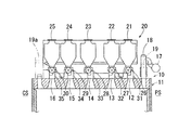
- a coke oven 10 shown in FIG. 1 has a plurality of carbonization chambers 11 (a partial cross section of one carbonization chamber is shown in FIG. 1), and a combustion chamber (not shown) is provided between adjacent carbonization chambers 11. ) Is provided.
- each carbonization chamber 11 a plurality of (for example, 3 or more, 5 or less, five in this case) coal inlets 12 to 16 extend from the extruder side PS of the carbonization chamber 11 to the guide vehicle side CS. , Are arranged side by side with a gap.
- a riser pipe (an example of a first gas suction unit) 18 connected to the dry main 17 is provided on the extruder side PS (first upper end portion) of each carbonization chamber 11.
- the riser pipe 18 has an ejector function, and the furnace gas generated in the carbonization chamber 11 can be forcibly discharged to the dry main 17.
- the ascending pipe 18 is provided with a pressure gauge 19 for measuring the gas pressure in the carbonization chamber 11.
- a jumper pipe (second pipe) that communicates the inside of the carbonizing chamber 11 with the inside of another carbonizing chamber near the carbonizing chamber 11 is connected to the guide wheel side CS (second upper end portion) of the carbonizing chamber 11.
- An example of the gas suction part) 19a may be provided.
- the jumper pipe 19a is, for example, a mini stand pipe disclosed in Japanese Patent Laid-Open No. 2008-150536. Instead of the jumper pipe 19a, a riser pipe having the same function as the riser pipe 18 described above may be provided.
- the rising pipe 18 and the jumper pipe 19a are respectively provided on the extruder side PS (first upper end portion) and the guide wheel side CS (second upper end portion) of the carbonization chamber 11,
- the gas in the carbonization chamber 11 is sucked from the ascending pipe 18 and the jumper pipe 19a and exhausted outside the carbonization chamber 11.
- the jumper pipe 19 sucks the gas in the carbonization chamber 11 through the riser pipe provided in the other carbonization chamber described above.
- Only the riser pipe (an example of the first gas suction part) may be provided on the guide wheel side CS (second upper end part).
- a coal loading vehicle 20 (moving machine) loaded with high-temperature coal is arranged so as to be able to move above each carbonization chamber 11.
- the coal loading vehicle 20 includes a plurality (here, 5) of coal receiving hoppers 21 to 25 for storing high-temperature coal from the front surface (extruder side PS) to the back surface (guide vehicle side CS) of the carbonization chamber 11. , Are arranged side by side with a gap. Under the coal receiving hoppers 21 to 25, excavators 26 to 30 for cutting out the stored high temperature coal are provided. Further, chutes 31 to 35 are provided below the cutting machines 26 to 30. By moving these chutes 31 to 35 up and down, the lower ends of these chutes 31 to 35 can be attached to and detached from the respective coal inlets 12 to 16 of the carbonization chamber 11.
- chute 31-35 is lowered and the lower ends of the chute 31-35 are connected to the coal inlets 12-16, and then the cutting machines 26-30 are driven so that the coal receiving hoppers 21-25 are driven.
- the high-temperature coal inside can be charged into the carbonization chamber 11 through the coal charging ports 12 to 16.
- the charging method of the high temperature coal which concerns on this embodiment is demonstrated.
- the high temperature coal is charged into the carbonization chamber 11 through the coal charging inlets 12 to 16 using a charging device as shown in FIG.
- the specific example of the charging method of this high temperature coal is demonstrated in detail.
- high-temperature coal is charged into each coal charging inlet so as to go from the coal charging inlet 16 farthest from the rising pipe 18 toward the rising pipe 18 (coal charging inlet 21 closest to the rising pipe 18).
- a starting order is determined, and high-temperature coal is charged into each coal charging inlet at predetermined time intervals in accordance with this charging start order.
- the coal charging inlets preferably have different priorities with respect to the charging start order of the high-temperature coal with respect to the coal charging inlets. That is, it is preferable that the timing for charging high temperature coal into each coal charging inlet is not the same.
- a cutting machine 30 above the coal charging inlet 16 a cutting machine 29 above the coal charging inlet 15, a cutting machine 28 above the coal charging inlet 14, and a cutting above the coal charging inlet 13.
- the cutting machines 26 to 30 are sequentially driven every predetermined time in the order of the machine 27 and the cutting machine 26 above the coal inlet 12.
- the gas generation amount when driving the cutting machine 27 above the coal charging port 13 is small (for example, when the predetermined time is long)
- the timing of driving the upper cutting machine 26 may be shorter than the predetermined time.
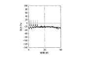
- the gas pressure in the carbonization chamber 11 increases rapidly as shown in FIG. Therefore, the depressurized state in the carbonization chamber 11 could always be maintained.
- the arrow in FIG. 2 indicates the drive start time of each of the cutting machines 26-30.
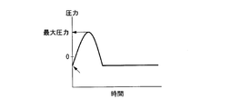
- 4A to 4C show the relationship between the drive start time of each of the cutting machines 26 to 30 and the maximum pressure of the in-furnace gas.
- a jumper pipe 19a is further provided at the upper end portion (upper end portion) of the carbonization chamber 11, an intermediate point between the rising pipe 18 and the jumper pipe 19a (equal distance from the rising pipe 18 and the jumper pipe 19a).
- the start order (ascending order) of the high-temperature coal for each coal charge inlet is determined. To do. Thereafter, according to this charging start order, high temperature coal is charged into each coal charging inlet at predetermined time intervals.
- the cutting machines 26 to 30 are sequentially driven at predetermined time intervals. At this time, the cutting machine 27 and the cutting machine 29 may be driven simultaneously or sequentially. Further, the cutting machine 26 and the cutting machine 30 may be driven simultaneously or sequentially.
- a cutting machine 28 above the coal charging inlet 14 a cutting machine 27 above the coal charging inlet 13, a cutting machine 26 above the coal charging inlet 12, a cutting machine 29 above the coal charging inlet 15,
- Each cutting is performed at predetermined intervals in the order of the cutting machine 30 above the coal inlet 16 or in the order of the cutting machine 28, the cutting machine 29, the cutting machine 30, the cutting machine 27, and the cutting machine 26.
- the machines 26 to 30 may be driven sequentially. That is, with respect to the coal charging inlet on the side of the rising pipe 18 from the intermediate point between the rising pipe 18 and the jumper pipe 19a, the coal charging inlet is directed from the intermediate point between the rising pipe 18 and the jumper pipe 19a toward the rising pipe 18.
- the order of starting the high temperature coal with respect to each coal inlet is determined.
- the coal charging inlet on the side of the jumper pipe 19a from the intermediate point between the rising pipe 18 and the jumper pipe 19a the coal charging inlet is directed from the intermediate point between the rising pipe 18 and the jumper pipe 19a to the jumper pipe 19a.
- the order of starting the high-temperature coal charging for each coal charging inlet is determined so that all of the inlet priorities are different.
- the cutting machines corresponding to two coal charging inlets that are substantially equidistant from the two gas suction portions may be driven simultaneously or sequentially. .
- each of the cutting machines 26 to 30 is preferably driven sequentially every predetermined time of 2 seconds or more and 10 seconds or less.
- the predetermined time (interval) will be described with reference to FIG.
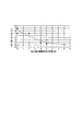
- FIG. 3 shows the relationship between the drive start time interval of each cutting machine and the maximum gas pressure in the carbonization chamber.
- the operating conditions other than the interval at which the driving of the cutting machine is started are the same as those in FIG.
- the driving start time interval of the cutting machine in FIG. 3 is 0 second.
- the gas pressure tends to be positive when the interval at which each cutting machine is started is less than 2 seconds.
- the reason why the gas pressure becomes positive is that the interval at which the cutting machine starts to be driven is too short, and the gas pressure that rises after the cutting machine is driven is reduced before the gas pressure increases. This is thought to be due to the gas pressure that rises after the machine is driven.
- the interval (predetermined time) is more preferably 3 seconds or more.
- the interval exceeds 10 seconds, the interval is too long, the time required for charging the high-temperature coal into all the carbonization chambers becomes long, and the operating rate of the coke oven is lowered. As shown in FIG.
- the interval is more preferably 8 seconds or less. Therefore, the drive start interval (predetermined time) of each cutting machine is preferably 3 seconds or more and 10 seconds or less.
- the upper limit of the most preferable interval (predetermined time) is 7 seconds, and the lower limit is 4 seconds.
- Each interval (predetermined time) may be the same or different.
- high-temperature coal of 100 ° C. or higher and 350 ° C. or lower is preferably used.
- the average temperature of the high-temperature coal charged into the carbonization chamber 11 is 100 ° C. or higher and 350 ° C. or lower, the effect of suppressing a rapid increase in gas pressure becomes significant. Therefore, the average temperature of the high temperature coal is preferably 100 ° C. or higher and 350 ° C. or lower.
- the coal loading vehicle 20 and each of the cutting machines 26 to 30 are used for charging high temperature coal into the coal charging inlet.
- the coal loading vehicle 20 can accurately weigh the amount of high-temperature coal, and can transport it as safely as possible while sealing the high-temperature coal (blocking from the outside air). Therefore, a charcoal vehicle is most preferably used as a method for transporting high-temperature coal.
- a belt conveyor or chain conveyor and chute may be used to charge high temperature coal into the coal inlet.
- coal inlets 12 to 16 are arranged side by side from the front side to the back side of the carbonization chamber 11 at an upper portion of the carbonization chamber 11 in which high temperature coal is charged. Moreover, the indoor volume of the carbonization chamber 11 is 44 m 3 .
- the furnace temperature in the carbonization chamber 11 was set to about 1000 to 1100 ° C.
- Various high temperature coals having different average temperatures were charged into the carbonization chamber 11 while changing the order and interval of the charging start.
- the gas pressure in the carbonizing chamber 11 during charging of high-temperature coal was measured with a pressure gauge 19 in the riser pipe 18 to investigate the presence or absence of outflow of furnace gas from the carbonizing chamber 11. The results are shown in Table 1.
- “Gas suction part” in Table 1 indicates the type of gas suction part provided in the carbonization chamber 11. That is, in the “rising pipe”, only the rising pipe 18 is provided on the extruder side PS of the carbonization chamber 11. In the “rising pipe + jumper pipe”, the raising pipe 18 is provided on the extruder side PS of the carbonization chamber 11, and the jumper pipe 19 a is provided on the guide wheel side CS. Further, the numbers described in the “order” of “starting charging of high temperature coal” are the numbers of the coal receiving hoppers 21 to 25 shown in FIG. Here, at the “arrows ( ⁇ )” between the numbers, the driving of the cutting machines 26 to 30 corresponding to the coal receiving hoppers 21 to 25 is sequentially started at predetermined “intervals”.
- the cutting machines 26 to 30 corresponding to the coal receiving hoppers 21 to 25 are simultaneously driven.
- the presence or absence of outflow of gas in the furnace was judged by visually confirming white smoke.
- white smoke could not be confirmed, it was judged as “No”, and when white smoke was confirmed, it was judged as “Yes”.
- the ascending pipe 18 was used as the gas suction part.
- charging of the high-temperature coal was started from the coal charging inlet 16 farthest from the rising pipe 18 toward the coal charging inlet 12 closest to the rising pipe 18. That is, the order of the coal receiving hopper 25, the coal receiving hopper 24, the coal receiving hopper 23, the coal receiving hopper 22, and the coal receiving hopper 21 (priority of coal charging inlet for charging high temperature coal) is “1” th, respectively. , “2”, “3”, “4”, and “5”.
- both the ascending pipe 18 and the jumper pipe 19a were used as the gas suction part.
- the coal inlet 14 that is substantially equidistant from both the riser pipe 18 and the jumper pipe 19a
- the cutting machines 26 to 30 of the coal receiving hoppers 21 to 25 were simultaneously driven.
- the rising pipe 18 was used as the gas suction part.
- tube 19a were used as a gas suction part.
- Example 1 the cutting machines 26 to 30 of the coal receiving hoppers 21 to 25 were sequentially driven. Therefore, in Examples 1 to 7, compared with Comparative Examples 1 and 2, the maximum pressure of the furnace gas could be reduced and the outflow of the furnace gas could be suppressed.
- Example 5 since the high-temperature coal charging start interval (predetermined time) was shorter than the lower limit of the optimum range (for example, 3 seconds or more) described above, the gas in the furnace slightly flowed out. However, this outflow amount in the furnace does not cause operational problems.
- the high-temperature coal charging start interval (predetermined time) was set to 3 seconds or more, so that the outflow of gas in the furnace could be prevented.
- the present invention has been described above with reference to the above embodiment. However, the present invention is not limited to the configuration described in the above embodiment. In other words, the present invention includes other embodiments and modifications that can be considered within the scope of the matters described in the claims. For example, a case where the high temperature coal charging method of the present invention is configured by combining a part or all of the above embodiment and the modified examples is also included in the scope of the right of the present invention.
Landscapes
- Chemical & Material Sciences (AREA)
- Engineering & Computer Science (AREA)
- Materials Engineering (AREA)
- Oil, Petroleum & Natural Gas (AREA)
- Organic Chemistry (AREA)
- Mechanical Engineering (AREA)
- General Engineering & Computer Science (AREA)
- Coke Industry (AREA)
- Filling Or Emptying Of Bunkers, Hoppers, And Tanks (AREA)
- Auxiliary Methods And Devices For Loading And Unloading (AREA)
Abstract
Description
本願は、2009年4月14日に、日本に出願された特願2009-98220号に基づき優先権を主張し、その内容をここに援用する。
まず、コークス炉に設けられた石炭塔の石炭積込み可能位置に装炭車を移動させ、石炭塔内の石炭をこの装炭車の複数の受炭ホッパーへ供給する。次に、石炭が供給された装炭車を、炭化室の上方に移動させた後、装炭車の複数の受炭ホッパーから、炭化室に設けられた各石炭装入口を介して、減圧状態の炭化室内に石炭を装入している。
従来から使用されている湿炭(装入温度が60℃以下の石炭)を炭化室に装入した場合には、装入初期に発生する石炭ガス量がそれほど多くない。そのため、上述した炉内ガスの流れが阻害された場合であっても、炉内ガスは、石炭装入装置と炭化室の石炭装入口との間のシール部からめったに漏洩しない。
しかし、近年、100℃以上に加熱した高温石炭が、炭化室に装入され始めている。この高温石炭を炭化室に装入すると、装入初期に多量の石炭ガスが発生する。そのため、上述した炉内ガスの流れが阻害されると、炭化室内のガス圧の上昇によってシール部から炉内ガスが漏洩する。
(1)上部に複数の石炭装入口が並べて配置され、前記上部の端部に第一のガス吸引部を有する炭化室内へ、高温石炭を装入する方法であって、前記第一のガス吸引部から最も離れた前記石炭装入口から前記第一のガス吸引部に向かうように、前記各石炭装入口に対する前記高温石炭の装入開始順序を決定し;この装入開始順序に従って、所定時間毎に前記高温石炭を装入する;高温石炭の装入方法。
(4)上記(1)または(2)に記載の高温石炭の装入方法では、前記高温石炭の平均温度が、100℃以上350℃以下であってもよい。
従って、炭化室に設けられた複数の石炭装入口を介して装炭車から炭化室内に高温石炭を装入する際に、炭化室内のガス圧の急激な上昇と、これに起因する炉内ガスの炉外への流出とを抑制することができる。
まず、本発明の一実施形態に係る高温石炭の装入方法を適用する装入装置について説明する。
図1に示すコークス炉10は、複数の炭化室11(図1には、1つの炭化室の部分断面を示す)を有しており、隣り合う炭化室11の間には燃焼室(図示しない)が設けられている。
なお、各炭化室11の押出機側PS(第一の上端部)には、ドライメーン17と接続される上昇管(第一のガス吸引部の一例)18が設けられている。この上昇管18は、エジェクタ機能を備えており、炭化室11内で発生した炉内ガスを、強制的にドライメーン17へ排出することができる。この上昇管18には、炭化室11内のガス圧を測定する圧力計19が設けられている。
本実施形態に係る高温石炭の装入方法では、例えば、図1に示すような装入装置を用いて、各石炭装入口12~16を介して炭化室11内へ高温石炭を装入する。以下に、この高温石炭の装入方法の具体例について詳しく説明する。
従来、高温石炭を装入する際には、各ホッパーの下部に設けられた各切出機を、同時に駆動していた。炭化室の床面及び壁面の温度が高いため、装入初期において炭化室の床面及び壁面に高温石炭が付着または衝突すると、大量のガスが発生する。その結果、炭化室内のガス圧が急激に上昇して一時的に減圧状態から正圧状態に変化し、各石炭装入口と各シュートの下端とを連接するシール部から炉内ガスが流出していた。なお、炭化室の床面に高温石炭が堆積してこの床面を覆うと、高温石炭の装入に伴うガスの発生量が低下する。したがって、炉内ガス圧を減圧状態に保つためには、上昇管を通して装入初期に発生するガスを円滑に炭化室の外へ排気する必要がある。
その結果、炉内ガスを上昇管にスムーズに流入させることができず、炭化室の室内ガス圧が高くなり、各石炭装入口と各シュートの下端とを連接するシール部から炉内ガスが流出する。この場合、特に、上昇管(ガス吸引部)から遠い位置で発生したガスは、上昇管に流入しにくいため、シール部から流出しやすい。
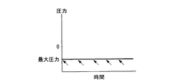
このように、所定時間間隔(ここでは、5秒程度の間隔)で各切出機26~30を順次駆動することで、図2に示すように、炭化室11内のガス圧が急激に増加することなく、常に炭化室11内の減圧状態を維持できた。ここで、図2中の矢印は、各切出機26~30の駆動開始時間を示している。
また、図4A~4C中に、各切出機26~30の駆動開始時間と炉内ガスの最大圧力との関係を示す。各切出機26~30を同時に駆動した場合には、図4Aに示すように、高温石炭の装入初期に炭化室11内のガス圧が急激に増加する。同様に、本実施形態と異なる装入開始順序(逆順)で高温石炭を装入した場合には、図4Bに示すように、ガス吸引部に近い側の石炭装入口から装入されて落下中の石炭によってガス吸引部に向かう炉内ガスの流れが阻害されるため、高温石炭の装入初期に炭化室11内のガス圧が急激に増加する。しかしながら、本実施形態では、図4Cに示すように、炭化室11内のガス圧の変動は、ほとんど見られない。図4A~4C中の矢印は、各切出機26~30の駆動開始時間を示している。
また、石炭装入口14の上方の切出機28、石炭装入口13の上方の切出機27、石炭装入口12の上方の切出機26、石炭装入口15の上方の切出機29、石炭装入口16の上方の切出機30の順番で、又は切出機28、切出機29、切出機30、切出機27、切出機26の順番で、所定時間毎に各切出機26~30を順次駆動してもよい。
すなわち、上昇管18とジャンパー管19aとの中間点より上昇管18側の石炭装入口について、上昇管18とジャンパー管19aとの中間点から上昇管18に向かうように、かつ、各石炭装入口の優先順位がすべて異なる(すなわち、各石炭装入口へ高温石炭を装入するタイミングがすべて同じにならない)ように、各石炭装入口に対する高温石炭の装入開始順序を決定する。同様に、上昇管18とジャンパー管19aとの中間点よりジャンパー管19a側の石炭装入口について、上昇管18とジャンパー管19aとの中間点からジャンパー管19aに向かうように、かつ、各石炭装入口の優先順位がすべて異なるように、各石炭装入口に対する高温石炭の装入開始順序を決定する。
石炭装入口の数が偶数である場合には、2つのガス吸引部から略等距離にある2つの石炭装入口に対応する切出機を同時に駆動してもよく、また順次駆動してもよい。
所定時間(間隔)について、図3を参照しながら説明する。図3は、各切出機の駆動開始時間の間隔と炭化室内の最大ガス圧力との関係を示している。なお、図3では、切出機の駆動を開始する間隔以外の操業条件は、上述した図2と同様である。全ての切出機を同時に駆動した場合、この図3中の切出機の駆動開始時間の間隔は、0秒である。
一方、間隔が10秒を超える場合、間隔が長過ぎて、全炭化室へ高温石炭を装入するために要する時間が長くなり、コークス炉の稼働率が低下する。図3に示すように、間隔が7~8秒になると、ガス圧が略一定となる傾向がある。そのため、作業効率の観点から、間隔は、8秒以下であることがより好ましい。
従って、各切出機の駆動開始間隔(所定時間)は、3秒以上10秒以下であることが好ましい。最も好ましい間隔(所定時間)の上限は、7秒、下限は、4秒である。なお、各間隔(所定時間)は、同一でもよく、また異なってもよい。
従って、高温石炭の平均温度は、100℃以上350℃以下であることが好ましい。高温石炭の平均温度の下限を150℃、更には200℃とすることで、上述した効果が更に顕著になる。
従って、炭化室11の上部に並べて配置された複数の石炭装入口12~16を介して装炭車20から炭化室11内に高温石炭を装入する際に、炭化室11内のガス圧の急激な上昇を抑制して、外部への炉内ガスの流出を防止できる。
なお、上記実施形態では、石炭装入口へ高温石炭を装入するために、装炭車20及び各切出機26~30を用いた。装炭車20は、高温石炭の装炭量を正確に秤量でき、高温石炭を密閉(外気と遮断)しながらできる限り安全に輸送できる。そのため、高温石炭の輸送方法として、装炭車が最も好適に用いられる。しかしながら、石炭装入口へ高温石炭を装入するために、ベルトコンベアまたはチェーンコンベア及びシュートを使用してもよい。
高温石炭を装入する炭化室11の上部には、5個の石炭装入口12~16が、炭化室11の正面から背面へかけて、間隔を有して並べて配置されている。また、炭化室11の室内容積は、44m3である。なお、炭化室11の炉内温度を1000~1100℃程度に設定した。
この炭化室11内に、異なる平均温度の各種高温石炭を、装入開始の順序と間隔とを変更して装入した。高温石炭の装入中の炭化室11内のガス圧を上昇管18内の圧力計19で測定し、炭化室11内からの炉内ガスの流出の有無を調査した。
この結果を、表1に示す。

また、「高温石炭の装入開始」の「順番」に記載された番号は、図1に示す各受炭ホッパー21~25の番号である。ここで、各番号の間の「矢印(→)」では、各受炭ホッパー21~25に対応する各切出機26~30の駆動を所定「間隔」で順番に開始する。また、「、」では、各受炭ホッパー21~25に対応する切出機26~30を同時に駆動する。
炉内ガスの流出の有無は、目視で白煙を確認することにより判断した。白煙を確認できない場合、「無」と判断し、白煙を確認できた場合、「有」と判断した。
なお、実施例1~3では、ガス吸引部として上昇管18を使用した。この場合には、上昇管18から最も離れた石炭装入口16から、上昇管18に最も近い石炭装入口12へ向けて高温石炭の装入を開始した。すなわち、受炭ホッパー25、受炭ホッパー24、受炭ホッパー23、受炭ホッパー22、及び受炭ホッパー21の順番(高温石炭を装入する石炭装入口の優先順位)は、それぞれ「1」番目、「2」番目、「3」番目、「4」番目、及び「5」番目である。実施例4~7では、ガス吸引部として上昇管18とジャンパー管19aとの双方を使用した。この場合には、上昇管18とジャンパー管19aの双方から略等距離にある石炭装入口14から、上昇管18に最も近い石炭装入口12とジャンパー管19aに最も近い石炭装入口16とへ向けて高温石炭の装入を開始した。
一方、比較例1及び2では、各受炭ホッパー21~25の各切出機26~30を同時に駆動した。なお、比較例1では、ガス吸引部として上昇管18を使用した。また、比較例2では、ガス吸引部として上昇管18とジャンパー管19aとの双方を使用した。
なお、実施例5では、高温石炭の装入開始の間隔(所定時間)が、上述した最適範囲(例えば、3秒以上)の下限値よりも短いため、炉内ガスが僅かに流出した。しかしながら、この炉内ガス流出量では、操業上の問題は、生じない。実施例1~4、6、7では、高温石炭の装入開始の間隔(所定時間)を3秒以上にしたため、炉内ガスの流出を防止できた。
比較例1及び2では、各受炭ホッパー21~25の各切出機26~30を同時に駆動した。そのため、図4Aに示すように、炉内ガスの最大圧力が急激に増加し、操業上問題となる量の炉内ガスが流出した。
本発明の高温石炭の装入方法を使用することで、高温石炭の装入初期に多量にガスが発生する条件において、ガス吸引部に近い側の石炭装入口から装入中の石炭によってガス吸引部に向かう炉内ガスの流れが阻害されないことを確認した。さらに、炭化室内のガス圧の急激な上昇を抑制して、炭化室からの発煙を抑制、更には防止できることを確認した。
11 炭化室
12~16 石炭装入口
17 ドライメーン
18 上昇管(ガス吸引部、第一のガス吸引部)
19 圧力計
19a ジャンパー管(ガス吸引部、第二のガス吸引部)
20 装炭車
21~25 受炭ホッパー
26~30 切出機
31~35 シュート
Claims (4)
- 上部に複数の石炭装入口が並べて配置され、前記上部の端部に第一のガス吸引部を有する炭化室内へ、高温石炭を装入する方法であって、
前記第一のガス吸引部から最も離れた前記石炭装入口から前記第一のガス吸引部に向かうように、前記各石炭装入口に対する前記高温石炭の装入開始順序を決定し;
この装入開始順序に従って、所定時間毎に前記高温石炭を装入する;
ことを特徴とする高温石炭の装入方法。 - 上部に複数の石炭装入口が並べて配置され、前記上部の両端部に第一のガス吸引部と第二のガス吸引部とを有する炭化室内へ、高温石炭を装入する方法であって、
前記第一のガス吸引部と前記第二のガス吸引部との中間点から前記第一のガス吸引部に向かうように、かつ、前記中間点から前記第二のガス吸引部に向かうように、前記各石炭装入口に対する前記高温石炭の装入開始順序を決定し;
この装入開始順序に従って、所定時間毎に前記高温石炭を装入する;
ことを特徴とする高温石炭の装入方法。 - 前記所定時間は、2秒以上10秒以下であることを特徴とする請求項1または2に記載の高温石炭の装入方法。
- 前記高温石炭の平均温度は、100℃以上350℃以下であることを特徴とする請求項1または2に記載の高温石炭の装入方法。
Priority Applications (5)
| Application Number | Priority Date | Filing Date | Title |
|---|---|---|---|
| BR122018009240-8A BR122018009240B1 (pt) | 2009-04-14 | 2010-04-14 | Processo para carga de carvão de alta temperatura |
| KR1020117023880A KR101430299B1 (ko) | 2009-04-14 | 2010-04-14 | 고온 석탄의 장입 방법 |
| JP2010529169A JP4685975B2 (ja) | 2009-04-14 | 2010-04-14 | 高温石炭の装入方法 |
| CN201080016300.9A CN102395652B (zh) | 2009-04-14 | 2010-04-14 | 高温煤的装入方法 |
| BRPI1013921-4A BRPI1013921B1 (pt) | 2009-04-14 | 2010-04-14 | Processo para carga de carvão de alta temperatura |
Applications Claiming Priority (2)
| Application Number | Priority Date | Filing Date | Title |
|---|---|---|---|
| JP2009-098220 | 2009-04-14 | ||
| JP2009098220 | 2009-04-14 |
Publications (1)
| Publication Number | Publication Date |
|---|---|
| WO2010119682A1 true WO2010119682A1 (ja) | 2010-10-21 |
Family
ID=42982355
Family Applications (1)
| Application Number | Title | Priority Date | Filing Date |
|---|---|---|---|
| PCT/JP2010/002721 Ceased WO2010119682A1 (ja) | 2009-04-14 | 2010-04-14 | 高温石炭の装入方法 |
Country Status (5)
| Country | Link |
|---|---|
| JP (1) | JP4685975B2 (ja) |
| KR (1) | KR101430299B1 (ja) |
| CN (1) | CN102395652B (ja) |
| BR (2) | BRPI1013921B1 (ja) |
| WO (1) | WO2010119682A1 (ja) |
Cited By (3)
| Publication number | Priority date | Publication date | Assignee | Title |
|---|---|---|---|---|
| JP2010235665A (ja) * | 2009-03-30 | 2010-10-21 | Nippon Steel Corp | 高温石炭の装入方法 |
| JP2012224673A (ja) * | 2011-04-15 | 2012-11-15 | Nippon Steel Corp | コークス炉の操業方法、コークス炉の制御システム及びコークス炉 |
| WO2025210952A1 (ja) * | 2024-04-03 | 2025-10-09 | 日本製鉄株式会社 | 廃プラスチックの処理方法 |
Families Citing this family (2)
| Publication number | Priority date | Publication date | Assignee | Title |
|---|---|---|---|---|
| KR102026028B1 (ko) | 2018-06-20 | 2019-09-26 | 양원석 | 소금 저장용 항아리 및 이를 이용한 소금 저장방법 |
| CN116254122B (zh) * | 2023-04-10 | 2026-01-27 | 新余钢铁股份有限公司 | 顶装式焦炉装煤方法 |
Citations (3)
| Publication number | Priority date | Publication date | Assignee | Title |
|---|---|---|---|---|
| JPS547003B2 (ja) * | 1974-04-03 | 1979-04-03 | ||
| JPS6239065Y2 (ja) * | 1981-07-14 | 1987-10-05 | ||
| JPS62257984A (ja) * | 1986-05-01 | 1987-11-10 | Kawasaki Steel Corp | コ−クス炉における無煙装炭方法 |
Family Cites Families (3)
| Publication number | Priority date | Publication date | Assignee | Title |
|---|---|---|---|---|
| US4094420A (en) * | 1974-04-03 | 1978-06-13 | Hartung, Kuhn & Co. | Charging of an oven chamber of a battery of coke ovens |
| JPH0913039A (ja) * | 1995-06-29 | 1997-01-14 | Kawasaki Steel Corp | コークス炉における装入炭槽 |
| TW409142B (en) * | 1997-03-25 | 2000-10-21 | Kawasaki Steel Co | Method of operating coke and apparatus for implementing the method |
-
2010
- 2010-04-14 BR BRPI1013921-4A patent/BRPI1013921B1/pt active IP Right Grant
- 2010-04-14 BR BR122018009240-8A patent/BR122018009240B1/pt active IP Right Grant
- 2010-04-14 CN CN201080016300.9A patent/CN102395652B/zh active Active
- 2010-04-14 JP JP2010529169A patent/JP4685975B2/ja active Active
- 2010-04-14 KR KR1020117023880A patent/KR101430299B1/ko active Active
- 2010-04-14 WO PCT/JP2010/002721 patent/WO2010119682A1/ja not_active Ceased
Patent Citations (3)
| Publication number | Priority date | Publication date | Assignee | Title |
|---|---|---|---|---|
| JPS547003B2 (ja) * | 1974-04-03 | 1979-04-03 | ||
| JPS6239065Y2 (ja) * | 1981-07-14 | 1987-10-05 | ||
| JPS62257984A (ja) * | 1986-05-01 | 1987-11-10 | Kawasaki Steel Corp | コ−クス炉における無煙装炭方法 |
Cited By (3)
| Publication number | Priority date | Publication date | Assignee | Title |
|---|---|---|---|---|
| JP2010235665A (ja) * | 2009-03-30 | 2010-10-21 | Nippon Steel Corp | 高温石炭の装入方法 |
| JP2012224673A (ja) * | 2011-04-15 | 2012-11-15 | Nippon Steel Corp | コークス炉の操業方法、コークス炉の制御システム及びコークス炉 |
| WO2025210952A1 (ja) * | 2024-04-03 | 2025-10-09 | 日本製鉄株式会社 | 廃プラスチックの処理方法 |
Also Published As
| Publication number | Publication date |
|---|---|
| BR122018009240B1 (pt) | 2019-07-16 |
| BRPI1013921A2 (pt) | 2016-04-05 |
| KR20110125270A (ko) | 2011-11-18 |
| BRPI1013921B1 (pt) | 2019-02-26 |
| KR101430299B1 (ko) | 2014-08-13 |
| CN102395652A (zh) | 2012-03-28 |
| JPWO2010119682A1 (ja) | 2012-10-22 |
| CN102395652B (zh) | 2015-04-01 |
| JP4685975B2 (ja) | 2011-05-18 |
Similar Documents
| Publication | Publication Date | Title |
|---|---|---|
| JP4685975B2 (ja) | 高温石炭の装入方法 | |
| EP2898048B1 (en) | Reduced output rate coke oven operation with gas sharing providing extended process cycle | |
| KR100797852B1 (ko) | 배기가스의 유량 제어 방법 | |
| AU2009272126B2 (en) | Method for producing iron ore pellets | |
| CN104781372A (zh) | 在捣固焦炉内共用挥发性物质的方法和装置 | |
| CN102378803B (zh) | 带有废气回流的焦化设备 | |
| JP5206080B2 (ja) | 火入れ時のコークス炉の炉体乾燥方法 | |
| JP6127684B2 (ja) | コークス炉炭化室の炉内圧調整装置及び炉内圧調整方法 | |
| JP4676838B2 (ja) | コークス炉の立ち上げ方法 | |
| JP2019508658A (ja) | 焼結装置及び焼結方法 | |
| MX2014000808A (es) | Metodo y regulador para ajustar el punto de perforacion por quemado en una maquina de sinterizacion. | |
| JP5092845B2 (ja) | 室炉式コークス炉及びその運転方法 | |
| JP6209820B2 (ja) | コークス炉炭化室の炉内圧調整装置及び炉内圧調整方法 | |
| JP6278185B2 (ja) | コークス炉の炭化室における付着カーボン燃焼除去方法 | |
| JP5182194B2 (ja) | 高温石炭の装入方法 | |
| RU91415U1 (ru) | Энергокомплекс для теплоснабжения горно-рудного предприятия | |
| JP4645354B2 (ja) | コークス炉装炭車、石炭の密閉受炭方法及び密閉装入方法 | |
| JP2009228065A (ja) | 焼結機主排風機の運転方法 | |
| JP4448476B2 (ja) | コークス炉装炭口周辺の付着カーボン焼却装置 | |
| JP5942488B2 (ja) | コークス炉装入車の石炭装入方法 | |
| SU1225848A1 (ru) | Способ бездымной загрузки коксовых печей угольной шихтой и машина дл его осуществлени | |
| JP2020007439A (ja) | コークス乾式消火設備 | |
| JP6481592B2 (ja) | コークス炉の立ち上げ方法 | |
| KR101241324B1 (ko) | 코크스 오븐 가스의 석탄 미립자 저감 방법 | |
| JP2010222538A (ja) | コークス炉の黒煙発生防止方法 |
Legal Events
| Date | Code | Title | Description |
|---|---|---|---|
| WWE | Wipo information: entry into national phase |
Ref document number: 201080016300.9 Country of ref document: CN |
|
| WWE | Wipo information: entry into national phase |
Ref document number: 2010529169 Country of ref document: JP |
|
| 121 | Ep: the epo has been informed by wipo that ep was designated in this application |
Ref document number: 10764269 Country of ref document: EP Kind code of ref document: A1 |
|
| ENP | Entry into the national phase |
Ref document number: 20117023880 Country of ref document: KR Kind code of ref document: A |
|
| WWE | Wipo information: entry into national phase |
Ref document number: 7874/DELNP/2011 Country of ref document: IN |
|
| NENP | Non-entry into the national phase |
Ref country code: DE |
|
| 122 | Ep: pct application non-entry in european phase |
Ref document number: 10764269 Country of ref document: EP Kind code of ref document: A1 |
|
| REG | Reference to national code |
Ref country code: BR Ref legal event code: B01A Ref document number: PI1013921 Country of ref document: BR |
|
| ENP | Entry into the national phase |
Ref document number: PI1013921 Country of ref document: BR Kind code of ref document: A2 Effective date: 20111011 |