WO2010116674A1 - Sheet press molding method and method for manufacturing separator for fuel cell - Google Patents
Sheet press molding method and method for manufacturing separator for fuel cell Download PDFInfo
- Publication number
- WO2010116674A1 WO2010116674A1 PCT/JP2010/002277 JP2010002277W WO2010116674A1 WO 2010116674 A1 WO2010116674 A1 WO 2010116674A1 JP 2010002277 W JP2010002277 W JP 2010002277W WO 2010116674 A1 WO2010116674 A1 WO 2010116674A1
- Authority
- WO
- WIPO (PCT)
- Prior art keywords
- sheet
- convex
- dummy
- pattern
- fuel cell
- Prior art date
Links
Images


Classifications
-
- B—PERFORMING OPERATIONS; TRANSPORTING
- B29—WORKING OF PLASTICS; WORKING OF SUBSTANCES IN A PLASTIC STATE IN GENERAL
- B29C—SHAPING OR JOINING OF PLASTICS; SHAPING OF MATERIAL IN A PLASTIC STATE, NOT OTHERWISE PROVIDED FOR; AFTER-TREATMENT OF THE SHAPED PRODUCTS, e.g. REPAIRING
- B29C43/00—Compression moulding, i.e. applying external pressure to flow the moulding material; Apparatus therefor
- B29C43/02—Compression moulding, i.e. applying external pressure to flow the moulding material; Apparatus therefor of articles of definite length, i.e. discrete articles
- B29C43/021—Compression moulding, i.e. applying external pressure to flow the moulding material; Apparatus therefor of articles of definite length, i.e. discrete articles characterised by the shape of the surface
-
- B—PERFORMING OPERATIONS; TRANSPORTING
- B29—WORKING OF PLASTICS; WORKING OF SUBSTANCES IN A PLASTIC STATE IN GENERAL
- B29C—SHAPING OR JOINING OF PLASTICS; SHAPING OF MATERIAL IN A PLASTIC STATE, NOT OTHERWISE PROVIDED FOR; AFTER-TREATMENT OF THE SHAPED PRODUCTS, e.g. REPAIRING
- B29C43/00—Compression moulding, i.e. applying external pressure to flow the moulding material; Apparatus therefor
- B29C43/02—Compression moulding, i.e. applying external pressure to flow the moulding material; Apparatus therefor of articles of definite length, i.e. discrete articles
-
- B—PERFORMING OPERATIONS; TRANSPORTING
- B29—WORKING OF PLASTICS; WORKING OF SUBSTANCES IN A PLASTIC STATE IN GENERAL
- B29C—SHAPING OR JOINING OF PLASTICS; SHAPING OF MATERIAL IN A PLASTIC STATE, NOT OTHERWISE PROVIDED FOR; AFTER-TREATMENT OF THE SHAPED PRODUCTS, e.g. REPAIRING
- B29C43/00—Compression moulding, i.e. applying external pressure to flow the moulding material; Apparatus therefor
- B29C43/32—Component parts, details or accessories; Auxiliary operations
- B29C43/36—Moulds for making articles of definite length, i.e. discrete articles
-
- B—PERFORMING OPERATIONS; TRANSPORTING
- B29—WORKING OF PLASTICS; WORKING OF SUBSTANCES IN A PLASTIC STATE IN GENERAL
- B29C—SHAPING OR JOINING OF PLASTICS; SHAPING OF MATERIAL IN A PLASTIC STATE, NOT OTHERWISE PROVIDED FOR; AFTER-TREATMENT OF THE SHAPED PRODUCTS, e.g. REPAIRING
- B29C59/00—Surface shaping of articles, e.g. embossing; Apparatus therefor
- B29C59/02—Surface shaping of articles, e.g. embossing; Apparatus therefor by mechanical means, e.g. pressing
-
- H—ELECTRICITY
- H01—ELECTRIC ELEMENTS
- H01M—PROCESSES OR MEANS, e.g. BATTERIES, FOR THE DIRECT CONVERSION OF CHEMICAL ENERGY INTO ELECTRICAL ENERGY
- H01M8/00—Fuel cells; Manufacture thereof
- H01M8/02—Details
-
- H—ELECTRICITY
- H01—ELECTRIC ELEMENTS
- H01M—PROCESSES OR MEANS, e.g. BATTERIES, FOR THE DIRECT CONVERSION OF CHEMICAL ENERGY INTO ELECTRICAL ENERGY
- H01M8/00—Fuel cells; Manufacture thereof
- H01M8/02—Details
- H01M8/0202—Collectors; Separators, e.g. bipolar separators; Interconnectors
- H01M8/0204—Non-porous and characterised by the material
- H01M8/0213—Gas-impermeable carbon-containing materials
-
- H—ELECTRICITY
- H01—ELECTRIC ELEMENTS
- H01M—PROCESSES OR MEANS, e.g. BATTERIES, FOR THE DIRECT CONVERSION OF CHEMICAL ENERGY INTO ELECTRICAL ENERGY
- H01M8/00—Fuel cells; Manufacture thereof
- H01M8/02—Details
- H01M8/0202—Collectors; Separators, e.g. bipolar separators; Interconnectors
- H01M8/0204—Non-porous and characterised by the material
- H01M8/0221—Organic resins; Organic polymers
-
- H—ELECTRICITY
- H01—ELECTRIC ELEMENTS
- H01M—PROCESSES OR MEANS, e.g. BATTERIES, FOR THE DIRECT CONVERSION OF CHEMICAL ENERGY INTO ELECTRICAL ENERGY
- H01M8/00—Fuel cells; Manufacture thereof
- H01M8/02—Details
- H01M8/0202—Collectors; Separators, e.g. bipolar separators; Interconnectors
- H01M8/0204—Non-porous and characterised by the material
- H01M8/0223—Composites
- H01M8/0226—Composites in the form of mixtures
-
- H—ELECTRICITY
- H01—ELECTRIC ELEMENTS
- H01M—PROCESSES OR MEANS, e.g. BATTERIES, FOR THE DIRECT CONVERSION OF CHEMICAL ENERGY INTO ELECTRICAL ENERGY
- H01M8/00—Fuel cells; Manufacture thereof
- H01M8/02—Details
- H01M8/0202—Collectors; Separators, e.g. bipolar separators; Interconnectors
- H01M8/0258—Collectors; Separators, e.g. bipolar separators; Interconnectors characterised by the configuration of channels, e.g. by the flow field of the reactant or coolant
- H01M8/026—Collectors; Separators, e.g. bipolar separators; Interconnectors characterised by the configuration of channels, e.g. by the flow field of the reactant or coolant characterised by grooves, e.g. their pitch or depth
-
- B—PERFORMING OPERATIONS; TRANSPORTING
- B29—WORKING OF PLASTICS; WORKING OF SUBSTANCES IN A PLASTIC STATE IN GENERAL
- B29C—SHAPING OR JOINING OF PLASTICS; SHAPING OF MATERIAL IN A PLASTIC STATE, NOT OTHERWISE PROVIDED FOR; AFTER-TREATMENT OF THE SHAPED PRODUCTS, e.g. REPAIRING
- B29C43/00—Compression moulding, i.e. applying external pressure to flow the moulding material; Apparatus therefor
- B29C43/02—Compression moulding, i.e. applying external pressure to flow the moulding material; Apparatus therefor of articles of definite length, i.e. discrete articles
- B29C43/021—Compression moulding, i.e. applying external pressure to flow the moulding material; Apparatus therefor of articles of definite length, i.e. discrete articles characterised by the shape of the surface
- B29C2043/023—Compression moulding, i.e. applying external pressure to flow the moulding material; Apparatus therefor of articles of definite length, i.e. discrete articles characterised by the shape of the surface having a plurality of grooves
- B29C2043/025—Compression moulding, i.e. applying external pressure to flow the moulding material; Apparatus therefor of articles of definite length, i.e. discrete articles characterised by the shape of the surface having a plurality of grooves forming a microstructure, i.e. fine patterning
-
- B—PERFORMING OPERATIONS; TRANSPORTING
- B29—WORKING OF PLASTICS; WORKING OF SUBSTANCES IN A PLASTIC STATE IN GENERAL
- B29K—INDEXING SCHEME ASSOCIATED WITH SUBCLASSES B29B, B29C OR B29D, RELATING TO MOULDING MATERIALS OR TO MATERIALS FOR MOULDS, REINFORCEMENTS, FILLERS OR PREFORMED PARTS, e.g. INSERTS
- B29K2105/00—Condition, form or state of moulded material or of the material to be shaped
- B29K2105/06—Condition, form or state of moulded material or of the material to be shaped containing reinforcements, fillers or inserts
- B29K2105/16—Fillers
-
- B—PERFORMING OPERATIONS; TRANSPORTING
- B29—WORKING OF PLASTICS; WORKING OF SUBSTANCES IN A PLASTIC STATE IN GENERAL
- B29K—INDEXING SCHEME ASSOCIATED WITH SUBCLASSES B29B, B29C OR B29D, RELATING TO MOULDING MATERIALS OR TO MATERIALS FOR MOULDS, REINFORCEMENTS, FILLERS OR PREFORMED PARTS, e.g. INSERTS
- B29K2105/00—Condition, form or state of moulded material or of the material to be shaped
- B29K2105/25—Solid
- B29K2105/253—Preform
- B29K2105/256—Sheets, plates, blanks or films
-
- B—PERFORMING OPERATIONS; TRANSPORTING
- B29—WORKING OF PLASTICS; WORKING OF SUBSTANCES IN A PLASTIC STATE IN GENERAL
- B29L—INDEXING SCHEME ASSOCIATED WITH SUBCLASS B29C, RELATING TO PARTICULAR ARTICLES
- B29L2031/00—Other particular articles
- B29L2031/34—Electrical apparatus, e.g. sparking plugs or parts thereof
- B29L2031/3468—Batteries, accumulators or fuel cells
-
- H—ELECTRICITY
- H01—ELECTRIC ELEMENTS
- H01M—PROCESSES OR MEANS, e.g. BATTERIES, FOR THE DIRECT CONVERSION OF CHEMICAL ENERGY INTO ELECTRICAL ENERGY
- H01M8/00—Fuel cells; Manufacture thereof
- H01M8/10—Fuel cells with solid electrolytes
- H01M2008/1095—Fuel cells with polymeric electrolytes
-
- Y—GENERAL TAGGING OF NEW TECHNOLOGICAL DEVELOPMENTS; GENERAL TAGGING OF CROSS-SECTIONAL TECHNOLOGIES SPANNING OVER SEVERAL SECTIONS OF THE IPC; TECHNICAL SUBJECTS COVERED BY FORMER USPC CROSS-REFERENCE ART COLLECTIONS [XRACs] AND DIGESTS
- Y02—TECHNOLOGIES OR APPLICATIONS FOR MITIGATION OR ADAPTATION AGAINST CLIMATE CHANGE
- Y02E—REDUCTION OF GREENHOUSE GAS [GHG] EMISSIONS, RELATED TO ENERGY GENERATION, TRANSMISSION OR DISTRIBUTION
- Y02E60/00—Enabling technologies; Technologies with a potential or indirect contribution to GHG emissions mitigation
- Y02E60/30—Hydrogen technology
- Y02E60/50—Fuel cells
-
- Y—GENERAL TAGGING OF NEW TECHNOLOGICAL DEVELOPMENTS; GENERAL TAGGING OF CROSS-SECTIONAL TECHNOLOGIES SPANNING OVER SEVERAL SECTIONS OF THE IPC; TECHNICAL SUBJECTS COVERED BY FORMER USPC CROSS-REFERENCE ART COLLECTIONS [XRACs] AND DIGESTS
- Y02—TECHNOLOGIES OR APPLICATIONS FOR MITIGATION OR ADAPTATION AGAINST CLIMATE CHANGE
- Y02P—CLIMATE CHANGE MITIGATION TECHNOLOGIES IN THE PRODUCTION OR PROCESSING OF GOODS
- Y02P70/00—Climate change mitigation technologies in the production process for final industrial or consumer products
- Y02P70/50—Manufacturing or production processes characterised by the final manufactured product
Definitions
- the present invention relates to a sheet press molding method and a method for manufacturing a fuel cell separator. More specifically, the present invention relates to a sheet press molding method using a resin composition sheet containing a filler (filler) at a high concentration and a method for producing a fuel cell separator using a resin composition sheet containing a carbonaceous material at a high concentration.
- This application claims priority on March 30, 2009 based on Japanese Patent Application No. 2009-082279 filed in Japan, the contents of which are incorporated herein by reference.
- a sheet press molding method has attracted attention as a molding method for thin-walled and large-area products. For example, it is used for molding a fuel cell separator.
- the sheet press molding method will be described with reference to an example of a method for manufacturing a fuel cell separator.
- Fuel cells are attracting attention from the viewpoints of environmental problems and energy problems because they are clean power generators that generate electricity through the reverse reaction of water electrolysis using hydrogen and oxygen, and do not produce any emissions other than water. Fuel cells are classified into several types depending on the type of electrolyte used. Among fuel cells, a polymer electrolyte fuel cell that operates at a low temperature is considered most promising for automobiles and consumer use. This fuel cell is usually a membrane electrode assembly (MEA :) formed by integrating a solid polymer membrane acting as a solid polymer electrolyte and a gas diffusion electrode carrying a pair of catalysts sandwiching the solid polymer membrane.
- MEA membrane electrode assembly
- the basic unit is a single cell having a Membrane-Electrode Assembly) and a separator that is sandwiched from the outside of the MEA and separates fuel gas and oxidizing gas. Then, by stacking a large number of single cells, high power generation can be achieved in the fuel cell.
- a gas flow path for supplying reaction gas to the gas diffusion electrode surface and carrying away generated gas and surplus gas is provided on the surface of the separator that constitutes the fuel cell in contact with the MEA. .
- hydrogen as a fuel is supplied to one gas diffusion electrode side
- an oxidant gas such as oxygen or air is supplied to the other gas diffusion electrode side, and between the two gas diffusion electrodes
- the separator is required to have excellent thermal conductivity, strength, etc. in addition to high gas impermeability capable of completely separating these gases and high conductivity for reducing internal resistance.
- the separator since the fuel cell is configured by stacking a large number of single cells, it is required that the separator be light and thin.
- metal materials and carbonaceous materials have been studied as materials for fuel cell separators. Since the metal material is excellent in mechanical properties, it can be mentioned that a thin separator can be obtained and that conductivity is high. However, the metal material has a large specific gravity and insufficient corrosion resistance.
- Patent Document 1 discloses isotropic graphite obtained by adding a binder to carbonaceous powder, heating and mixing, then performing CIP molding (Cold Isostatic Pressing), then firing and graphitizing.
- CIP molding Cold Isostatic Pressing
- Patent Document 2 discloses a method for producing a carbon thin plate in which a paper containing carbon powder or carbon fiber is impregnated with a thermosetting resin, laminated and pressure-bonded, and cured and fired.
- Patent Document 3 discloses a method for manufacturing a fuel cell separator in which a phenol resin molding material is injection-molded using a mold, and the molded product thus obtained is fired.
- a fired material is used as a material for a separator for a fuel cell.
- the fired material exhibits high conductivity and heat resistance, but has a problem that it is easily brittle fractured, and a problem that the time required for firing is long and productivity is poor.
- a material that requires a cutting process such as a slicing process in the process of manufacturing a separator has a low productivity and a high cost. There are many.
- a method of manufacturing a separator for a fuel cell by performing sheet press molding that press-molds a sheet-like material containing a carbonaceous material having conductivity.
- Such a method is excellent in productivity, and is particularly preferably used when a thin separator is produced.
- the bulk density of the obtained fuel cell separator varies greatly, so that the conductivity, mechanical strength, airtightness, etc. There was an inconvenience that the variation was large.
- Patent Document 4 discloses a first sheet made of a flexible graphite sheet and a second sheet made of a flexible graphite sheet from which a portion corresponding to the flow path has been removed. And a method of manufacturing a separator for a fuel cell, which forms a flow path and a through hole by press forming the laminated sheet and increases the bulk density of the peripheral region. Further, in Patent Document 5, after forming irregularities on the surface of the expanded graphite sheet so that the density difference of the expanded graphite is less than 30%, a predetermined irregular shape is formed using a pressing die corresponding to the irregular shape portion. Describes a technique for forming a separator for a fuel cell from an expanded graphite molded body molded in the above.
- Patent Document 4 a flexible graphite sheet is used, and in Patent Document 5, an expanded graphite sheet is used. Since flexible graphite sheets and expanded graphite sheets are porous, it is essential that a difference in bulk density occurs in parts with different thicknesses of the resulting molded product when press-molding a concavo-convex pattern using these sheets. Inevitable. For this reason, it has been required to further reduce the variation in characteristics due to the variation in the bulk density of the fuel cell separator. In addition, the flexible graphite sheet and the expanded graphite sheet have a disadvantage in that defects such as cracks and swelling are likely to occur on the surface by performing press molding.
- Patent Document 6 includes a curable resin composition containing an elastomer having a Mooney viscosity (ML 1 + 4 (100 ° C.)) of 25 or more and a carbon material in a mass ratio of 70 to 5:30 to 95.
- a fuel cell separator comprising a cured body obtained by curing an uncured sheet formed using a conductive curable resin composition with a compression molding machine is disclosed.
- the conventional sheet-like material containing a filler such as a carbonaceous material and a resin composition increases the filler content and press-molds this to produce a molded product having a refined pattern.
- a filler such as a carbonaceous material and a resin composition
- the moldability becomes very poor and the thickness deviation of the molded product becomes large.
- This problem is the same not only when the filler is a carbonaceous material but also when the filler is another filler such as silica or alumina.
- the gas flow path pattern tends to be miniaturized in order to improve the power generation efficiency of the fuel cell.
- a separator for a fuel cell having a refined gas flow path pattern is manufactured by press molding a sheet-like material containing a conventional resin composition and a carbonaceous material, as described above, Since the formability of the sheet-like material is poor, there arises a problem that the plate thickness deviation of the separator becomes large.
- the present invention has been made to solve the above problems, and even if a sheet-like material containing a filler and a resin composition contains a large amount of filler, it is press-molded. Accordingly, it is an object of the present invention to provide a sheet press molding method capable of obtaining a molded product having a small thickness deviation when a molded product is manufactured.
- the present invention provides a sheet-like material containing a carbonaceous material and a resin composition, even if it contains a large amount of carbonaceous material in order to obtain high conductivity. It is an object of the present invention to provide a method for producing a fuel cell separator with excellent productivity, which can efficiently produce a separator for a fuel cell having a small thickness, a small thickness deviation, a high strength and a high conductivity.
- the present invention includes, for example, the following items [1] to [10].
- [1] By pressing a sheet-like material containing a resin composition and 60 to 95% by volume of a filler using a pair of molds having a predetermined concavo-convex pattern consisting of concave and convex portions on at least one side, A step of forming a molded product having a concavo-convex pattern portion to which the concavo-convex pattern has been transferred, and, as the pair of molds, a total volume of convex portions formed inside, and between the convex portion and the inner side surface A sheet press molding method using a dummy pattern comprising a dummy recess or a dummy protrusion that cancels out the difference from the total volume of the recesses disposed between the protrusions.
- the sheet press molding method of the present invention uses a pair of molds having a predetermined concavo-convex pattern composed of at least one of a concave portion and a convex portion, and a sheet-like material containing 60 to 95% by volume of a filler and a resin composition
- the sheet-like material containing the filler and the resin composition may contain a large amount of filler, or the concavo-convex pattern may be miniaturized.
- a molded product is manufactured by press molding, a molded product with a small thickness deviation can be obtained.
- the method for producing a fuel cell separator of the present invention uses a pair of molds having a predetermined concavo-convex pattern comprising at least one of a concave portion and a convex portion, and 80 to 98% by mass of a carbonaceous material and a resin composition.
- a fuel cell separator having a flow path pattern to which the concavo-convex pattern has been transferred by pressurizing a sheet-like material comprising: a convex portion formed inside as the pair of molds
- a dummy pattern comprising dummy recesses or dummy protrusions is provided in the interior to offset the difference between the total volume and the total volume of the recesses disposed between the protrusions and the inner side surfaces and between the protrusions. Therefore, the volume of the convex portion of the fuel cell separator is the same as the volume of the concave portion of the fuel cell separator, and is pressed against the convex portion of the mold during the pressing process.
- a fuel cell separator of the present invention As a sheet-like material containing a carbonaceous material and a resin composition, a material containing a large amount of carbonaceous material is used, and this is press-molded. Thus, a fuel cell separator having a small thickness deviation, high strength and high conductivity can be obtained.
- a fuel cell separator having a flow path pattern is formed by pressurizing a sheet material using a pair of molds. Separator can be obtained, and can be manufactured more efficiently than when firing or cutting is performed.
- FIG. 1 is a view for explaining an example of a sheet press molding method using a conventional sheet-like material
- FIG. 1 (A) is a cross-sectional view showing an example of a mold used in the sheet press molding method. is there.
- FIGS. 1B to 1D are process diagrams showing an example of a conventional sheet press forming method.
- FIG. 2A is a process diagram for explaining an example of a sheet press molding method of the present invention and a method of manufacturing a fuel cell separator of the present invention.
- FIG. 2B is a process diagram for explaining an example of the sheet press molding method of the present invention and the method of manufacturing the fuel cell separator of the present invention.
- FIG. 1 is a view for explaining an example of a sheet press molding method using a conventional sheet-like material
- FIG. 1 (A) is a cross-sectional view showing an example of a mold used in the sheet press molding method. is there.
- FIGS. 1B to 1D are process diagrams showing an example of a conventional sheet
- FIG. 2C is a process diagram for explaining an example of the sheet press molding method of the present invention and the method for producing the fuel cell separator of the present invention.
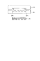
- FIG. 2D is a schematic diagram for explaining one modification of the sheet press molding method of the present invention and the method for producing the fuel cell separator of the present invention.
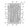
- FIG. 3A is a plan view of the fuel cell separator of the embodiment.
- 3B is a cross-sectional view taken along the line A-A ′ of FIG. 3A.
- FIG. 3C is a plan view of a fuel cell separator of a comparative example.
- 3D is a cross-sectional view taken along the line B-B 'of FIG. 3C.
- FIG. 4 is a plan view showing the fuel cell separator of the example.
- FIG. 5A is a graph showing the evaluation results of the plate thickness deviation of the fuel cell separator of the example.
- FIG. 5B is a graph showing the evaluation results of the plate thickness deviation of the fuel cell separator of the
- FIG. 1 is a view for explaining an example of a sheet press molding method using a conventional sheet-like material
- FIG. 1 (A) is a cross-sectional view showing an example of a mold used in the sheet press molding method. is there.
- FIGS. 1B to 1D are process diagrams showing an example of a conventional sheet press forming method.
- a mold 10 shown in FIG. 1A includes a lower mold 11 and an upper mold 12.
- the lower mold 11 has a predetermined uneven pattern 13 composed of a plurality of convex portions 13a, 13b, 13c, and 13d (four in the example shown in FIG. 1A).
- a filler is placed between the lower mold 11 and the upper mold 12.
- the sheet-like material 21 containing a resin composition is arrange
- the lower mold 11, the upper mold 12, and the sheet-like material 21 are set to temperatures at which the sheet-like material 21 is softened and deformable, A pressing process is performed in which the mold 12 is pressurized to compress the sheet-like material 21 and is held for a predetermined time. As a result, the sheet-like material 21 is formed as shown in FIG. 1D, and a molded product 23 to which the uneven pattern 13 is transferred is formed.
- the inventor prepares the sheet-like material 21 in which only the content of the filler contained in the sheet-like material 21 is variously changed, and uses the same mold 10 for each sheet-like material 21 under the same conditions. After molding, the relationship between the content of the filler of the sheet-like material 21 and the thickness deviation of the molded product 23 was examined. As a result, when the sheet-like material 21 having a small filler content and a relatively large resin composition content is press-molded, a molded product 23 having a substantially uniform thickness is obtained. It was found that when the sheet-like material 21 having a large amount was press-molded, the thickness difference of the obtained molded product 23 was large.
- the sheet material 21 having a relatively high resin composition content has good fluidity of the sheet material softened by the pressing process. For this reason, the softened sheet-like material that has become excessive due to the pressing step is smoothly extruded in the outer peripheral (xy (plane)) direction. Thus, it is estimated that a molded body 21 having a substantially uniform thickness can be obtained. On the other hand, the sheet-like material 21 having a large filler content hardly flows even when the pressing process is performed.
- the softened sheet-like material that has become excessive due to the pressing process remains in place without being pushed in the outer periphery (xy (plane)) direction, and is mainly compressed and deformed in the thickness (z) direction. To do. As a result, it is estimated that the thickness deviation of the molded product 23 becomes large.
- the inventor has repeatedly studied the distribution of the thickness of the molded product 23. As a result, it was found that when the sheet-like material 21 having a high filler content was used, the plate thickness was increased at the central portion of the molded product 23 and the plate thickness was decreased at the outer peripheral portion of the molded product 23. Furthermore, the tendency of the thickness distribution of the molded product 23 is such that the greater the content of the filler contained in the sheet-like material 21, and the finer the uneven pattern 13 transferred to the molded product 23 is. , Found to be remarkable. The tendency of the distribution of the thickness of the molded product 23 is that the thickness of the molded product 23 is increased at the central portion of the molded product 23 because the sheet-like material softened by the pressing process does not easily flow out. In this case, it is presumed that the softened sheet material is likely to flow out, so that the plate thickness is reduced.
- the present inventor has made extensive studies based on the above knowledge, and when press-molding a molded product having a concavo-convex pattern portion, the total volume of the convex portions formed inside, the convex portions and the internal portions Using a die provided with a dummy pattern formed of a dummy recess or a dummy projection that cancels out the difference from the total volume of the recesses disposed between the side surfaces of the projections and between the projections.
- the volume By making the volume the same as the volume of the concave portion of the molded body, the softened sheet-like material that is pressed and extruded to the convex portion of the mold is opposed to the concave portion of the mold when the pressing process is performed.
- the sheet press according to the present invention Method and manufacturing method of the fuel cell separator of the present invention using this to occur to.
- the total volume of the convex part inside the mold, the convex part and the internal part are determined by the dummy pattern.
- the difference between the total volume of the concave portions arranged between the side surfaces and between the convex portions is offset, and the total volume of the convex portions and the total volume of the concave portions inside the mold are the same, so the pressing step.
- the softened sheet-like material corresponding to the volume of the convex part of the mold is extruded around the convex part of the mold. Embedded in the recess.
- the softened sheet-like material flows smoothly, so that the thickness deviation of the molded product is reduced.
- press-molding a molded product having a concavo-convex pattern portion for example, the total volume of the convex portions inside the mold, and the concave portions disposed between the convex portions and the side surfaces inside and between the convex portions.
- the amount of the softened sheet-like material that is pushed out around the convex portion of the die by the pressing step and embedded in the concave portion of the die Since the amount of the softened sheet-like material is not uniform, the softened sheet-like material pushed out around the convex portion becomes excessive or insufficient. For this reason, the softened sheet-like material does not flow smoothly, and the thickness deviation of the molded product increases.
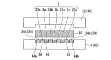
- FIG. 2A to 2C are process diagrams for explaining an example of the sheet press molding method of the present invention and the method for producing the fuel cell separator of the present invention.
- a sheet-like material 20 is formed using a pair of dies 40 including an upper die 12 and a lower die 1 having a predetermined uneven pattern 3.
- This is a sheet press molding method for forming a molded product 30 having a concavo-convex pattern portion 32 formed by transferring the concavo-convex pattern 3 by applying pressure, as shown in FIG. 2C.
- the sheet-like material 20 contains 60 to 95% by volume of a filler and a resin composition.
- the filler can be appropriately determined according to the use of the molded article 30 and the like, and is not particularly limited.
- inorganic fine particles such as silica, alumina, and titanium oxide, organic fine particles such as polyethylene and polystyrene, and fibers And carbonaceous materials.
- a carbonaceous material it is preferable to use a carbonaceous material as a filler.
- a resin composition which comprises the sheet-like material 20 a thermosetting resin, a thermoplastic resin, etc. are mentioned.
- the content of the filler contained in the sheet material 20 is set to 60 to 95% by volume.
- the specific gravity differs depending on the type of filler, when a carbonaceous material is used as the filler, the content of the filler of 60 to 95% by volume corresponds to the content of 80 to 98% by mass.
- the filler is a carbonaceous material, such as when a fuel cell separator is manufactured as the molded article 30, the content of the filler is more preferably 85 to 98% by mass.
- the content (volume%) of the filler is calculated from the specific gravity of the resin composition and the filler. Even if the content of the filler is less than the above range, the sheet press molding method of the present invention can be used.
- the effect of applying the present invention is small and effective. Absent. Further, when a fuel cell separator is manufactured as the molded article 30 and the filler is a carbonaceous material, if the filler content is less than the above range, the conductivity of the molded article 30 is insufficient. It becomes. On the other hand, when the content of the filler exceeds the above range, the fluidity of the sheet-like material softened by performing the pressing process is lowered, and thus a molded product 30 having a sufficiently small plate thickness deviation cannot be obtained.
- the present invention is suitable for manufacturing a fuel cell separator having a thickness of 2 mm or less as the molded product 30.
- the thickness of the fuel cell separator is 2 mm or less, the thickness is sufficiently thin.
- the sheet-like material 20 has a uniform thickness.
- the sheet-like material 20 having a uniform thickness is obtained by, for example, applying a component that becomes a sheet-like material containing 60 to 95% by volume of a filler and a resin composition in the resin field such as a roll mill, an extruder, a kneader, and a Banbury mixer. It can form by the method etc. which shape
- the component used as the sheet-like material containing a filler and a resin composition can be grind
- a homogenizer for the pulverization, a homogenizer, a Willet pulverizer, a high-speed rotary pulverizer (hammer mill, pin mill, cage mill, blender) or the like can be used.
- a method of pelletizing using an extruder, a ruder, a kneader or the like, or a method of using a bread type granulator or the like can be used.
- a mold 40 shown in FIG. 2A includes a lower mold 1 and an upper mold 12.
- the inside 14 of the lower mold 1 has the uneven pattern 3 and the dummy pattern 24.
- the interior 14 of the mold 40 includes not only the interior of the lower mold 1 but also the interior of the upper mold 12 and means the entire interior in which the sheet-like material 20 is accommodated during press molding. is doing. Therefore, in FIG. 2A, the lower mold, which is one of the pair of molds 40, is described as an example in which both the concave and convex pattern 3 and the dummy pattern 24 are provided.
- the concave / convex pattern may be provided on one of the pair of molds, and the dummy pattern may be provided on the other mold.
- the dummy convex portion 224 a is provided only on the upper mold 212.
- a molded product 230 having a cross-sectional shape as shown in FIG. 2D is obtained.
- the concave / convex pattern and the dummy pattern are provided only on the lower mold, but the concave / convex pattern and the dummy pattern may be provided on both molds.
- the number of the concave / convex patterns and the dummy patterns provided in the pair of molds is not particularly limited, and may be one each or plural. Further, the number of the concave and convex patterns and the dummy patterns may be the same or different.
- corrugated patterns may be the same, and a part or all may differ.
- the concavo-convex pattern 3 can be determined according to the use of the molded product 30 and the like, and is not particularly limited. However, in the present embodiment, as shown in FIG.
- the plurality of stripe-shaped convex portions 23a, 23b, 23c, and 23d and concave portions 3a, 3b, and 3c arranged between the convex portions 23a, 23b, 23c, and 23d are used.
- the convex portions 23a, 23b, 23c, and 23d have the same shape in sectional view, but the convex portion shapes may be different from each other.
- the shape of the concave / convex pattern 3 corresponds to the shape of a recess (groove) for a flow path of the fuel cell separator, and the concave / convex pattern portion of the molded product 30. 32 is a flow path pattern.
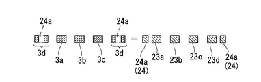
- the dummy pattern 24 cancels the difference between the total volume of the convex portions 23a, 23b, 23c, and 23d formed in the interior 14 of the mold 40 and the total volume of the concave portions.
- the total volume of the protrusions not including the dummy pattern 24 is the total volume of the protrusions 23a, 23b, 23c, and 23d protruding from the bottom of the lower mold 1 as shown in FIG. 2A. .
- the total volume of the recesses not including the dummy pattern 24 is a volume between the virtual surface along the upper surface of the lower mold 1 and the lower mold 1, and the convex portions 23 a, 23 b,
- a plane having a quadrangular sectional view having the same height as the convex portions 23a, 23b, 23c, and 23d is formed between the convex portions 23a, 23b, 23c, and 23d and the side surface 14b of the interior 14.
- the striped dummy convex portions 24 a and 24 a are provided in parallel so as to sandwich the concave / convex pattern 3. Therefore, when the dummy pattern 24 is included, as shown in FIG. 2B, the volume of the concave portion 3d disposed between the convex portions 23a, 23b, 23c, 23d and the side surface 14b of the interior 14 is equal to the dummy convex portions 24a, 24a.
- the volume of the convex portion decreases, the volume of the convex portions 24a and 24a increases, the difference between the total volume of the convex portions and the total volume of the concave portions is offset, and the total volume of the convex portions and the total concave portion The volume is almost equal.
- the dummy convex portions 24a and 24a are provided as the dummy pattern 24.
- the total volume of the convex portions is the total of the concave portions.
- a dummy recess is provided as a dummy pattern.
- the shape of the dummy pattern 24 may be any volume (volume) that can offset the difference between the total volume of the convex portions and the total volume of the concave portions, and is not particularly limited. However, as shown in FIG. In the case of the dummy convex portions 24a and 24a, the height of the dummy convex portions 24a and 24a is preferably the same height as the convex portions 23a, 23b, 23c and 23d of the convex pattern 3, and the dummy pattern is a dummy concave portion. In this case, it is preferable that the depth is the same as that of the recesses 3a, 3b, and 3c of the uneven pattern.
- the pressing process was performed as compared with the case where the height (depth) of the dummy convex portion (dummy concave portion) was different from the height (depth) of the convex portion (concave portion) of the uneven pattern 3. Since variations in the amount of compressive deformation of the sheet-like material 20 at the time are reduced, the thickness deviation of the molded product 30 can be further reduced.
- the arrangement of the dummy patterns 24 is not particularly limited, but is preferably provided at a plurality of locations.
- the dummy pattern 24 is provided at a plurality of locations, variation in the amount of compressive deformation of the sheet-like material 20 when the pressing process is performed is reduced as compared with the case where the dummy pattern is provided at one location. Therefore, the thickness deviation of the molded product 30 can be further reduced.
- two dummy patterns 24 are provided in parallel so as to sandwich the concavo-convex pattern 3, but may be one place or three or more places.
- the arrangement of the dummy patterns is not limited to the example shown in FIG. 2A, but is preferably determined according to the arrangement of the concave portions and the convex portions constituting the concave / convex pattern.
- the arrangement of the dummy patterns is not limited to the example shown in FIG. 2A, but is preferably determined according to the arrangement of the concave portions and the convex portions constituting the concave / convex pattern.
- a dummy is placed in the vicinity of a region where the unevenness of the concave and convex portions constituting the concave-convex pattern is large. It is preferable to arrange a pattern. For example, when providing a dummy convex part as a dummy pattern, it is preferable to arrange
- a plurality of dummy patterns so as to surround the uneven pattern 3. If the dummy pattern is provided on the outer peripheral portion of the concavo-convex pattern 3, when a fuel cell separator is manufactured as the molded product 30, the conductivity of the fuel cell separator may be hindered, and the flowability of the flow path pattern may be hindered. There is no fear of coming.
- the concave / convex pattern is used to effectively reduce variations in the amount of compressive deformation of the sheet-like material 20 when the pressing process is performed. It is preferable to arrange a dummy pattern inside.
- a dummy pattern may be arranged on the inner surface of the mold 12). In this case, it is preferable to arrange a plurality of dummy patterns so as to surround the concavo-convex pattern 3 as in the case where the dummy pattern is provided in the mold having the concavo-convex pattern 3.
- the dummy pattern is provided in another mold facing the concave / convex pattern 3, the dummy pattern is arranged in the concave / convex pattern when the width of the concave and convex portions constituting the concave / convex pattern is not uniform. It is preferable.
- the dummy pattern 24 may be provided outside the concave / convex pattern 3 or provided inside the concave / convex pattern 3 as long as the molded product 30 is not hindered. Also good.
- the dummy pattern 24 is preferably provided at a position corresponding to a region serving as a gas supply hole of the fuel cell separator.
- the pattern formed by transferring the dummy pattern 24 to the molded product 30 can be used as a guide or the like when forming the gas supply hole in the fuel cell separator. In this case, the gas supply hole can be easily formed, which is preferable.
- the gas supply hole of the fuel cell separator is usually formed by providing a hole penetrating the fuel cell separator. Therefore, although the pattern formed by transferring the dummy pattern disappears by forming the gas supply hole, there is no problem even if it disappears since it is after the formation of the fuel cell separator.
- the outer edge of the flow path pattern which is the concave / convex pattern portion 32 of the molded product 30, or the outer edge of a manifold hole (gas supply hole) for passing fuel gas or the like.
- a packing is disposed in the part.
- the dummy pattern 24 is disposed avoiding the position where the packing is disposed.
- the dummy pattern which consists of a dummy recessed part or a dummy convex part, after arrange
- the dummy pattern is also used as a packing, it is provided at a position where the packing is to be disposed.
- the sheet-like material 20 used when manufacturing the separator for fuel cells as the molded article 30 contains the carbonaceous material (A) as a filler and the resin composition (B) as essential components.
- Carbonaceous material (A) include carbon black, carbon fiber (pitch-based, PAN-based), amorphous carbon, expanded graphite, quiche graphite, artificial graphite, natural graphite, vapor grown carbon fiber, carbon nanotube, fullerene, etc. Examples thereof include one or a mixture of two or more selected from the quality materials.
- carbon fiber pitch-based, PAN-based
- amorphous carbon expanded graphite, quiche graphite, artificial graphite, natural graphite, gas phase method
- the carbonaceous material (A) preferably contains boron, and among them, artificial graphite containing boron can be used particularly suitably.
- Carbon black which is an example of the carbonaceous material (A), is obtained by incomplete combustion of natural gas or the like, ketjen black obtained by thermal decomposition of acetylene, acetylene black, hydrocarbon oil or natural gas. Examples include furnace carbon and thermal carbon obtained by thermal decomposition of natural gas.
- Carbon fibers (Carbon fiber) Carbon fibers (pitch-based, PAN-based) as an example of the carbonaceous material (A) include pitch-based made from heavy oil, by-product oil, coal tar, PAN-based made from polyacrylonitrile, etc. It is done.
- the average fiber length of the carbon fibers is obtained by measuring the number average fiber length by image analysis of 100 fiber lengths observed using SEM (manufactured by JEOL Ltd., JSM-5510).
- the carbon fiber referred to here is one having a ratio of (major axis length / minor axis length) of 10 or more.
- Amorphous carbon which is an example of the carbonaceous material (A) is a method in which a phenol resin is cured and baked and pulverized to obtain a powder, or a phenol resin is cured in a spherical, indefinite shape powder and baked. What was obtained by the method of processing etc. is mentioned. In order to obtain highly conductive amorphous carbon, it is preferable to perform a heat treatment at 2000 ° C. or higher.
- Examples of the expanded graphite which is an example of the carbonaceous material (A) include graphite having a highly crystal structure such as natural graphite and pyrolytic graphite, a mixed solution of concentrated sulfuric acid and nitric acid, concentrated sulfuric acid and hydrogen peroxide solution.
- a graphite intercalation compound is formed by immersion in a strong oxidizing solution mixed with the powder, washed with water and then rapidly heated to expand the powder in the C-axis direction of the graphite crystal, Examples thereof include a powder obtained by pulverizing a sheet rolled.
- Examples of the quiche graphite that is an example of the carbonaceous material (A) include planarly crystallized carbon that is precipitated as molten pig iron is lowered in temperature by hot metal pretreatment or the like. Since this quiche graphite is generated as a mixture with slag and iron oxide, a powder obtained by collecting high-purity quiche graphite by beneficiation and further pulverizing it to a size suitable for the use is preferably used.
- artificial graphite As artificial graphite which is an example of the carbonaceous material (A), for example, graphitized powder obtained by the method shown below is used. Usually, in order to obtain artificial graphite, coke is produced. As a raw material for coke, petroleum pitch, coal pitch, or the like is used. These raw materials are carbonized into coke.
- a method in which coke is pulverized and then graphitized a method in which coke itself is graphitized and then pulverized, or a calcined product formed by adding a binder to coke and calcined (coke)
- a method in which the calcined product is co-graphitized and then pulverized into powder. Since it is better for the raw material coke or the like to have as little crystals as possible, a heat-treated material at 2000 ° C. or lower, preferably 1200 ° C. or lower is suitable.
- a method for graphitizing a method using an Atchison furnace in which powder is placed in a graphite crucible and directly energized, a method of heating powder with a graphite heating element, or the like can be used.
- the carbonaceous material (A) preferably contains 0.1 to 50% by mass of vapor grown carbon fiber and / or carbon nanotube. More preferably, the content is 0.1 to 45% by mass, and still more preferably 0.2 to 40% by mass.
- vapor grown carbon fiber for example, an organic compound such as benzene, toluene, natural gas, or hydrocarbon gas is used as a raw material, and pyrolysis is performed at 800 to 1300 ° C. together with hydrogen gas in the presence of a transition metal catalyst such as ferrocene.
- a transition metal catalyst such as ferrocene.
- Examples thereof include carbon fibers obtained by reacting and having a fiber length of about 0.5 to 10 ⁇ m and a fiber diameter of 200 nm or less. A more preferable size of the fiber diameter is 160 nm or less, and further preferably 120 nm or less. If the fiber diameter is larger than 200 nm, the effect of obtaining high conductivity is reduced, which is not preferable.
- the carbon fiber obtained by the above method is preferably graphitized at about 2300 to 3200 ° C.
- the graphitization process here is performed in inert gas atmosphere with graphitization catalysts, such as boron, boron carbide, beryllium, aluminum, and silicon.
- Carbon nanotube In recent years, not only the mechanical strength of carbon nanotubes but also the field emission function and the hydrogen storage function have attracted industrial attention, and the magnetic function has begun to pay attention.
- This type of carbon nanotube is also called graphite whisker, filamentous carbon, graphite fiber, ultrafine carbon tube, carbon tube, carbon fibril, carbon microtube, carbon nanofiber, etc., and the fiber diameter is about 0.5-100 nm belongs to.
- Carbon nanotubes include single-walled carbon nanotubes having a single graphite film forming a tube and multi-walled carbon nanotubes having multiple layers. In the present invention, both single-walled and multi-walled carbon nanotubes can be used. However, it is preferable to use single-walled carbon nanotubes because a composition having higher conductivity and mechanical strength tends to be obtained.
- Carbon nanotubes are produced, for example, by the arc discharge method, laser evaporation method, thermal decomposition method, etc. described in Saito / Panto “Basics of Carbon Nanotubes” (pages 23-57, published by Corona, 1998)
- a hydrothermal method a centrifugal separation method, an ultrafiltration method, an oxidation method or the like.
- high temperature treatment is performed in an inert gas atmosphere at about 2300 to 3200 ° C. to remove impurities.
- high temperature treatment is performed at about 2300 to 3200 ° C. in an inert gas atmosphere together with a graphitization catalyst such as boron, boron carbide, beryllium, aluminum and silicon.
- Carbonaceous material containing boron Boron is preferably contained in the carbonaceous material (A) in an amount of 0.05 to 5% by mass, more preferably 0.06 to 4% by mass, and further preferably 0.06 to 3% by mass. preferable. If the boron content is less than 0.05% by mass, the intended highly conductive carbonaceous material tends to be difficult to obtain. Further, even if the boron content exceeds 5 mass%, it tends to be difficult to contribute to the improvement of the conductivity of the carbonaceous material, the amount of impurities increases, and other physical properties are deteriorated. A tendency tends to occur.
- ICP induction plasma emission spectrometry
- ICP-MS induction plasma emission spectrometry mass spectrometry
- sulfuric acid and nitric acid are added to a carbonaceous material containing boron as a sample, heated to 230 ° C. by microwaves (digester method), and further perchloric acid (HClO 4 ).
- a method of diluting a product decomposed by adding water and applying it to an ICP emission spectrometer and measuring the amount of boron is exemplified.
- Examples of the method for incorporating boron into the carbonaceous material (A) include carbon black, carbon fiber, amorphous carbon, expanded graphite, quiche graphite, artificial graphite, natural graphite, vapor grown carbon fiber, carbon nanotube, fullerene and the like. 1 type or a mixture of two or more types selected from the above carbonaceous materials and boron simple substance B, B 4 C, BN, B 2 O 3 , H 3 BO 3, etc. And a method of graphitizing at 3200 ° C.
- the carbonaceous material containing boron not only becomes nonuniform, but also increases the possibility of sintering during graphitization.
- the boron source is made into a powder having a particle size of about 50 ⁇ m or less, preferably about 20 ⁇ m or less, and then mixed with the powder of the carbonaceous material. Is preferred.
- the form of boron contained in the carbonaceous material containing boron is not particularly limited as long as boron and / or boron compounds are mixed in the carbonaceous material. More preferably, boron and / or boron compounds are present between the layers of the graphite crystals, or carbon atoms that form the graphite crystals are partially substituted with boron atoms.
- the bond between the boron atom and the carbon atom may be any bond mode such as a covalent bond or an ionic bond.
- Coke used in the production of carbonaceous materials, artificial graphite and natural graphite used as carbonaceous materials, etc. are pulverized by high-speed rotary pulverizer (hammer mill, pin mill, cage mill) and various ball mills (rolling mill, vibration mill). , Planetary mills), stirring mills (bead mills, attritors, distribution pipe mills, annular mills) and the like. Further, a screen mill, a turbo mill, a supermicron mill, a jet mill, etc., which are fine pulverizers, can be used by selecting the conditions. Coke, natural graphite, and the like are preferably pulverized using these pulverizers, and the pulverization conditions are selected at that time, and the powder is classified as necessary, and the average particle size and particle size distribution are controlled and used.
- any method for classifying coke powder, artificial graphite powder, natural graphite powder, etc. any method can be used as long as separation is possible.
- a sieving method or a forced vortex type centrifugal classifier micron separator, turboplex, turboclassic
- Airflow classifiers such as fire and super separators and inertia classifiers (improved virtual impactor and elbow jet) can be used.
- a wet sedimentation method or a centrifugal classification method can be used.
- Resin composition (B) examples include a thermosetting resin and a thermoplastic resin. From the viewpoint of durability of the fuel cell separator, it is preferable to use a resin whose melting point or glass transition temperature of the fuel cell separator is 120 ° C. or higher. In order to improve the hot water resistance of the fuel cell separator, 1,2-polybutadiene, 3,4-polyisoprene, novolac epoxy resin, novolac phenol resin, polyethylene, polypropylene are used as the resin composition (B).
- a carbonaceous material (A) comprising at least one component selected from polymethylpentene, polystyrene, polyphenylene sulfide, polycycloolefin, polybutene-1, polyphenylene ether, polyether ether ketone, fluororesin, or liquid crystal polymer (A) And 2 to 20% by mass in the conductive resin composition containing the resin composition (B), particularly 1,2-polybutadiene, 3,4-polyisoprene, polyethylene, polypropylene, 1 selected from polybutene-1 Or it is preferably contained in the content.
- the sheet-like material 20 used when the molded product 30 is a fuel cell separator includes a carbonaceous material (A) as a filler and a resin composition (B), as well as a monomer and a reaction as necessary. Initiators, elastomers, rubbers, resin modifiers, and the like can be included. Furthermore, the sheet-like material 20 used when the molded product 30 is a fuel cell separator has a glass fiber for the purpose of improving hardness, strength, conductivity, moldability, durability, weather resistance, water resistance, and the like.
- Additives such as whiskers, metal oxides, organic fibers, UV stabilizers, antioxidants, mold release agents, lubricants, water repellents, thickeners, low shrinkage agents, hydrophilicity-imparting agents, as necessary It can be included.
- the sheet press molding method of the present embodiment uses a pair of molds 40 each having a predetermined concavo-convex pattern 3 composed of concave portions 3a, 3b, 3c and convex portions 23a, 23b, 23c, 23d on at least one side.
- the volume of the convex part of the molded body 30 becomes the same as the volume of the concave part of the molded body 30, and when the pressing process is performed, the softened sheet-like material 20 that is pressed and extruded to the convex part of the mold 40.
- the sheet-like material 20 including the filler and the resin composition includes a large amount of filler, or the uneven pattern 3 is refined. Even if it exists, when the molded product 30 is manufactured by press molding this, the molded product 30 with a small thickness deviation is obtained.
- the manufacturing method of the separator for fuel cells of this embodiment manufactures the separator for fuel cells as the molded article 30 using the sheet press molding method of this embodiment using the sheet-like material 20 whose filler is a carbonaceous material. Since it is a method, as the sheet-like material 20 containing a carbonaceous material and a resin composition, a material containing a large amount of a carbonaceous material is used, and by pressing this, a thickness deviation is small, high strength and high A fuel cell separator having conductivity is obtained. Further, in the method for manufacturing a fuel cell separator according to the present embodiment, by using a fine pattern as the uneven pattern 3, a fuel cell separator having a small thickness variation and a small flow path pattern can be easily obtained. Is obtained.
- a fuel cell separator having a flow path pattern is formed by pressurizing a sheet material using a pair of molds. Battery separators can be produced efficiently and are suitable for mass production.
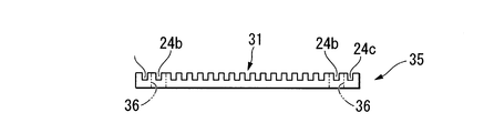
- the separator for a fuel cell of the example was manufactured as a molded article using the sheet press molding method of the present invention. That is, by using the following pair of molds having a concavo-convex pattern and pressing the sheet-like material shown below, the flow path pattern 31 to which the concavo-convex pattern has been transferred and a plurality of concave portions to which the dummy pattern has been transferred A fuel cell separator 35 shown in FIG. 3 having 24b, 24c, 24d, and 24e on one side was obtained.
- 3A to 3D are diagrams showing fuel cell separators of Examples and Comparative Examples.
- FIG. 3A is a plan view of the fuel cell separator of the embodiment, and FIG. 3B is a cross-sectional view taken along the line AA ′ of FIG. 3A.
- FIG. 3C is a plan view of a fuel cell separator of a comparative example, and FIG. 3D is a cross-sectional view taken along the line BB ′ of FIG. 3C.
- the total volume of the convex portions formed inside is smaller than the total volume of the concave portions, but when the dummy pattern is included, The difference between the total volume of the convex portions formed inside and the total volume of the concave portions is offset and is the same.
- Uneven pattern (corresponding to the flow path pattern 31 in FIGS. 3A and 3B): a cross section having a depth of 0.5 mm, a width lower side (bottom width) of 2.1 mm, a width upper side (upper width) of 1.9 mm, and an average width of 2 mm
- the trapezoidal convex part (groove in the fuel cell separator) has a length of 160 mm and a width of 62 mm at a pitch of 4 mm (interval between the upper sides of the width of 2 mm), and the length direction is the length direction of the convex part (groove). It was arranged in stripes so that
- Dummy pattern A dummy convex part (corresponding to the concave parts 24b, 24c, 24d, and 24e in FIGS. 3A and 3B) having a height (depth) of 0.5 mm so as to double surround the flow path pattern 31. It was provided on the outer periphery of the flow path pattern 31. In addition, the area of each dummy convex part was adjusted so that the total volume of the convex part formed inside the lower metal mold
- the inner dummy convex portion (corresponding to the concave portion 24b in FIGS.
- the outer dummy convex portions (corresponding to the concave portions 24c in FIGS. 3A and 3B) were arranged at four locations outside the inner dummy convex portions, avoiding the position where the packing is arranged.
- the dummy convex portion (corresponding to the concave portion 24d in FIG.
- 3A is the outer peripheral portion of the flow path pattern 31, and is the central portion of the fuel cell separator 35, which is a region where the inner dummy convex portion is not disposed. Two places were provided. Furthermore, dummy convex portions (corresponding to the concave portions 24e in FIG. 3A) are provided at the four corner portions of the fuel cell separator 35, respectively.
- the average particle size of the artificial graphite fine powder and the boron-containing natural graphite was measured by the following method. First, 50 mg of a sample was weighed and added to 50 ml of distilled water. Furthermore, after adding 0.2 ml of 2% Triton (surfactant; manufactured by Wako Pure Chemical Industries, Ltd.) aqueous solution and ultrasonically dispersing for 3 minutes, laser diffraction scattering method (Microtrac HRA apparatus manufactured by Nikkiso Co., Ltd.) was used. The number average particle size was measured.
- the content of the carbonaceous material in the obtained sheet-like material was 85% by mass, the content of boron in the carbonaceous material was 2% by mass, and the density was 1.5 g / cm 3 .
- the boron content was measured by the method described in [0058]. Moreover, about the density of boron, the specific gravity measured based on the underwater substitution method (Archimedes method) prescribed
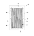
- the measurement position of the thickness of the fuel cell separator 35 is the dimension shown in FIG. 4 (the dimension shown in FIG. 4) inside the blank area provided with a width of 5 mm along the outer edge.
- the unit is (mm)) and is divided into approximately four equal parts in the length direction and the width direction, respectively, and the divided line in the length direction and the inner boundary line of the blank area (dotted lines indicated by reference numerals 1 to 5 in FIG.
- FIG. 5A is a graph showing the evaluation results of the plate thickness deviation of the fuel cell separator of the example.
- FIGS. 3C and 3D A fuel cell separator of the comparative example shown in FIGS. 3C and 3D was formed in the same manner as in the example except that the same mold was used except that no dummy pattern was provided. And the plate
- FIG. 5B is a graph showing the evaluation results of the plate thickness deviation of the fuel cell separator of the comparative example.
- the present invention can be applied to a sheet press molding method and a fuel cell separator manufacturing method.
Abstract
Description
本願は、2009年3月30日に、日本に出願された特願2009-082279号に基づき優先権を主張し、その内容をここに援用する。 The present invention relates to a sheet press molding method and a method for manufacturing a fuel cell separator. More specifically, the present invention relates to a sheet press molding method using a resin composition sheet containing a filler (filler) at a high concentration and a method for producing a fuel cell separator using a resin composition sheet containing a carbonaceous material at a high concentration.
This application claims priority on March 30, 2009 based on Japanese Patent Application No. 2009-082279 filed in Japan, the contents of which are incorporated herein by reference.
したがって、セパレータには、これらのガスを完全に分離できる高い気体不透過性と、内部抵抗を小さくするための高い導電性に加え、熱伝導性、強度等に優れていることが要求される。また、前述の通り燃料電池は、単セルを多数個積層することにより構成されているため、セパレータの軽量、薄型化が要求されている。 A gas flow path (groove) for supplying reaction gas to the gas diffusion electrode surface and carrying away generated gas and surplus gas is provided on the surface of the separator that constitutes the fuel cell in contact with the MEA. . Using such a gas flow path, hydrogen as a fuel is supplied to one gas diffusion electrode side, an oxidant gas such as oxygen or air is supplied to the other gas diffusion electrode side, and between the two gas diffusion electrodes By connecting an external load circuit to the device, the device having the above structure is operated as a fuel cell.
Therefore, the separator is required to have excellent thermal conductivity, strength, etc. in addition to high gas impermeability capable of completely separating these gases and high conductivity for reducing internal resistance. Further, as described above, since the fuel cell is configured by stacking a large number of single cells, it is required that the separator be light and thin.
例えば、特許文献1には、炭素質粉末に結合材を加えて加熱混合後CIP成形(Cold Isostatic Pressing;冷間等方圧加工法)し、次いで焼成、黒鉛化して得られた等方性黒鉛材に熱硬化性樹脂を含浸、硬化処理したのち、スライス加工して固体高分子型燃料電池用のセパレータとするという煩雑な工程が開示されている。また、特許文献2には、炭素粉末または炭素繊維を含む紙に熱硬化性樹脂を含浸し、積層圧着し、硬化・焼成する炭素薄板の製造法が開示されている。また、特許文献3には、フェノール樹脂成形材料を、金型を用いて射出成形し、得られた成形加工品を焼成する燃料電池用セパレータの製造方法が開示されている。 Carbonaceous materials are lightweight, have high electrical conductivity, and are excellent in thermal conductivity, strength, etc., and their thin molding technology and mass production are being studied.
For example,
しかし、炭素質材料を含むシート状の材料をプレス成形して燃料電池セパレータを製造した場合、得られた燃料電池用セパレータの嵩密度のバラツキが大きいため、導電性、機械的強度、気密性等のバラツキが大きいという不都合があった。 As a technique for solving this problem, for example, there is a method of manufacturing a separator for a fuel cell by performing sheet press molding that press-molds a sheet-like material containing a carbonaceous material having conductivity. Such a method is excellent in productivity, and is particularly preferably used when a thin separator is produced.
However, when a fuel cell separator is manufactured by press-molding a sheet-like material containing a carbonaceous material, the bulk density of the obtained fuel cell separator varies greatly, so that the conductivity, mechanical strength, airtightness, etc. There was an inconvenience that the variation was large.
このようにシート状の材料として、樹脂組成物と炭素質材料とを含むものを用いた場合、可撓性黒鉛シートおよび膨張黒鉛シートを使用した場合に比べて、プレス成形することにより得られた成形品の特性のバラツキを小さくすることができるし、プレス成形時における欠損も生じにくい。 As a technique for solving this problem, there is a method of obtaining a molded product by press-molding a sheet-like material containing a resin composition and a carbonaceous material. For example, Patent Document 6 includes a curable resin composition containing an elastomer having a Mooney viscosity (ML 1 + 4 (100 ° C.)) of 25 or more and a carbon material in a mass ratio of 70 to 5:30 to 95. A fuel cell separator comprising a cured body obtained by curing an uncured sheet formed using a conductive curable resin composition with a compression molding machine is disclosed.
As described above, when a sheet-shaped material containing a resin composition and a carbonaceous material was used, it was obtained by press molding as compared with the case of using a flexible graphite sheet and an expanded graphite sheet. Variations in the characteristics of the molded product can be reduced, and defects during press molding are less likely to occur.
[1] 少なくとも一方に凹部と凸部とからなる所定の凹凸パターンを有する一対の型を用いて、樹脂組成物と60~95体積%の充填材とを含むシート状材料を加圧することにより、前記凹凸パターンの転写された凹凸パターン部を有する成形品を形成する工程を備え、前記一対の型として、内部に形成された凸部の合計体積と、前記凸部と前記内部の側面との間および前記凸部間に配置された凹部の合計容積との差を相殺するダミー凹部またはダミー凸部からなるダミーパターンが、前記内部に設けられたものを用いることを特徴とするシートプレス成形方法。
[2] 前記凸部の合計体積が前記凹部の合計容積よりも少なく、前記ダミーパターンがダミー凸部からなるものであることを特徴とする[1]に記載のシートプレス成形方法。
[3] 前記ダミーパターンが複数個所に設けられていることを特徴とする[1]または[2]に記載のシートプレス成形方法。
[4] 前記シート状材料が均一な厚みを有するものであることを特徴とする[1]~[3]のいずれかに記載のシートプレス成形方法。
[5] 前記充填材が炭素質材料であることを特徴とする[1]~[4]のいずれかに記載のシートプレス成形方法。
[6] 前記ダミー凸部の高さが、前記凹凸パターンの凸部の高さと同じであることを特徴とする[2]に記載のシートプレス成形方法。 That is, the present invention includes, for example, the following items [1] to [10].
[1] By pressing a sheet-like material containing a resin composition and 60 to 95% by volume of a filler using a pair of molds having a predetermined concavo-convex pattern consisting of concave and convex portions on at least one side, A step of forming a molded product having a concavo-convex pattern portion to which the concavo-convex pattern has been transferred, and, as the pair of molds, a total volume of convex portions formed inside, and between the convex portion and the inner side surface A sheet press molding method using a dummy pattern comprising a dummy recess or a dummy protrusion that cancels out the difference from the total volume of the recesses disposed between the protrusions.
[2] The sheet press molding method according to [1], wherein the total volume of the convex portions is smaller than the total volume of the concave portions, and the dummy pattern is formed of dummy convex portions.
[3] The sheet press molding method according to [1] or [2], wherein the dummy pattern is provided at a plurality of locations.
[4] The sheet press molding method according to any one of [1] to [3], wherein the sheet-like material has a uniform thickness.
[5] The sheet press molding method according to any one of [1] to [4], wherein the filler is a carbonaceous material.
[6] The sheet press molding method according to [2], wherein the height of the dummy protrusion is the same as the height of the protrusion of the uneven pattern.
[8] 前記凸部の合計体積が前記凹部の合計容積よりも少なく、前記ダミーパターンがダミー凸部からなるものであることを特徴とする[7]に記載の燃料電池用セパレータの製造方法。
[9] 前記ダミーパターンが複数の領域に設けられていることを特徴とする[7]または[8]に記載の燃料電池用セパレータの製造方法。
[10] 前記ダミーパターンが、前記燃料電池用セパレータのガス供給穴となる領域に対応する位置に設けられていることを特徴とする[7]~[9]のいずれかに記載の燃料電池用セパレータの製造方法。
[11] 前記ダミー凸部の高さが、前記凹凸パターンの凸部の高さと同じであることを特徴とする[8]に記載の燃料電池用セパレータの製造方法。 [7] By pressing a sheet-like material containing a resin composition and 80 to 98% by mass of a carbonaceous material using a pair of molds having a predetermined concavo-convex pattern consisting of concave and convex portions on at least one side A step of forming a separator for a fuel cell having a flow path pattern to which the uneven pattern is transferred, and as the pair of molds, a total volume of protrusions formed inside, the protrusions and the interior of the protrusions A fuel having a dummy pattern formed of a dummy recess or a dummy projection that cancels out a difference from a total volume of the recesses disposed between the side surfaces and between the projections. Manufacturing method of battery separator.
[8] The method for producing a fuel cell separator according to [7], wherein the total volume of the convex portions is smaller than the total volume of the concave portions, and the dummy pattern is formed of dummy convex portions.
[9] The method for manufacturing a fuel cell separator according to [7] or [8], wherein the dummy pattern is provided in a plurality of regions.
[10] The fuel cell according to any one of [7] to [9], wherein the dummy pattern is provided at a position corresponding to a region serving as a gas supply hole of the fuel cell separator. Separator manufacturing method.
[11] The method for producing a fuel cell separator according to [8], wherein the height of the dummy protrusion is the same as the height of the protrusion of the uneven pattern.
また、本発明の燃料電池用セパレータの製造方法においては、シート状材料を一対の型を用いて加圧することにより、流路用パターンを有する燃料電池用セパレータを形成するので、厚みの薄い燃料電池用セパレータが得られるとともに、焼成や切削加工を行う場合と比較して効率よく製造できる。 Also, the method for producing a fuel cell separator of the present invention uses a pair of molds having a predetermined concavo-convex pattern comprising at least one of a concave portion and a convex portion, and 80 to 98% by mass of a carbonaceous material and a resin composition. And forming a fuel cell separator having a flow path pattern to which the concavo-convex pattern has been transferred by pressurizing a sheet-like material comprising: a convex portion formed inside as the pair of molds A dummy pattern comprising dummy recesses or dummy protrusions is provided in the interior to offset the difference between the total volume and the total volume of the recesses disposed between the protrusions and the inner side surfaces and between the protrusions. Therefore, the volume of the convex portion of the fuel cell separator is the same as the volume of the concave portion of the fuel cell separator, and is pressed against the convex portion of the mold during the pressing process. Softened sheet material is extruded, it will be embedded in smooth portion that is opposed to the mold recess. As a result, according to the method for manufacturing a fuel cell separator of the present invention, as a sheet-like material containing a carbonaceous material and a resin composition, a material containing a large amount of carbonaceous material is used, and this is press-molded. Thus, a fuel cell separator having a small thickness deviation, high strength and high conductivity can be obtained.
In the method for manufacturing a fuel cell separator according to the present invention, a fuel cell separator having a flow path pattern is formed by pressurizing a sheet material using a pair of molds. Separator can be obtained, and can be manufactured more efficiently than when firing or cutting is performed.
ここで、本発明を説明しやすくするために、従来の充填材と樹脂組成物とを含むシート状材料をプレス成形して成形品を形成するシートプレス成形方法について、図面を用いて説明する。図1は、従来のシート状材料を用いるシートプレス成形方法の一例を説明するための図であり、図1(A)は、シートプレス成形方法で用いられる金型の一例を示した断面図である。また、図1(B)~図1(D)は、従来のシートプレス成形方法の一例を示した工程図である。 Hereinafter, a sheet press molding method and a fuel cell separator manufacturing method of the present invention will be described in detail with reference to the drawings.
Here, in order to facilitate the explanation of the present invention, a sheet press molding method for forming a molded product by press molding a sheet-like material including a conventional filler and a resin composition will be described with reference to the drawings. FIG. 1 is a view for explaining an example of a sheet press molding method using a conventional sheet-like material, and FIG. 1 (A) is a cross-sectional view showing an example of a mold used in the sheet press molding method. is there. FIGS. 1B to 1D are process diagrams showing an example of a conventional sheet press forming method.
図1(A)に示す金型10を用いて、成形品を形成するには、まず、図1(B)に示すように、下金型11と上金型12と間に、充填材と樹脂組成物とを含むシート状材料21を配置させる。次いで、図1(C)に示すように、下金型11、上金型12、シート状材料21を、シート状材料21が軟化されて変形可能とされる温度とし、下金型11および上金型12を加圧してシート状材料21を圧縮して、所定の時間保持するプレス工程を行う。このことにより、図1(D)に示すようにシート状材料21が成形されて、凹凸パターン13の転写された成形品23が形成される。 A
In order to form a molded product using the
その結果、充填材の含有量が少なく、相対的に樹脂組成物の含有量の多いシート状材料21をプレス成形した場合、略均一な厚みを有する成形品23が得られるが、充填材の含有量の多いシート状材料21をプレス成形した場合、得られた成形品23の板厚偏差が大きいことが分かった。 Here, the inventor prepares the sheet-
As a result, when the sheet-
これに対して、充填材の含有量の多いシート状材料21は、プレス工程を行ってもほとんど流動しない。このため、プレス工程を行うことによって過剰となった軟化したシート状材料は、外周(x-y(平面))方向に押し出されずに、その場に留まり、主に厚み(z)方向に圧縮変形する。その結果、成形品23の板厚偏差が大きくなるものと推定される。 This inventor repeated examination about the cause which brought such a result as shown below. That is, the
On the other hand, the sheet-
このような成形品23の板厚の分布の傾向は、成形品23の中央部では、プレス工程を行うことによって軟化したシート状材料が流れ出にくいため板厚が厚くなり、成形品23の外周部では、軟化したシート状材料が流れ出やすいため板厚が薄くなったことによるものと、推定される。 Further, the inventor has repeatedly studied the distribution of the thickness of the molded
The tendency of the distribution of the thickness of the molded
これに対し、凹凸パターン部を有する成形品をプレス成形する際に、例えば、型の内部における凸部の合計体積と、凸部と内部の側面との間および凸部間に配置された凹部の合計容積とが異なっていて、ダミーパターンが設けられていない型を用いた場合、プレス工程を行うことにより型の凸部周辺に押し出される軟化したシート状材料の量と、型の凹部に埋め込まれる軟化したシート状材料の量とが均一でないため、凸部周辺に押し出される軟化したシート状材料が過剰になったり、不足したりする。このため、軟化したシート状材料がスムーズに流動されず、成形品の板厚偏差が大きくなる。 More specifically, when a mold having the above-mentioned dummy pattern is used when press-molding a molded product having a concavo-convex pattern part, the total volume of the convex part inside the mold, the convex part and the internal part are determined by the dummy pattern. The difference between the total volume of the concave portions arranged between the side surfaces and between the convex portions is offset, and the total volume of the convex portions and the total volume of the concave portions inside the mold are the same, so the pressing step As a result, the softened sheet-like material corresponding to the volume of the convex part of the mold is extruded around the convex part of the mold. Embedded in the recess. As a result, the softened sheet-like material flows smoothly, so that the thickness deviation of the molded product is reduced.
On the other hand, when press-molding a molded product having a concavo-convex pattern portion, for example, the total volume of the convex portions inside the mold, and the concave portions disposed between the convex portions and the side surfaces inside and between the convex portions. When using a mold that has a different total volume and is not provided with a dummy pattern, the amount of the softened sheet-like material that is pushed out around the convex portion of the die by the pressing step and embedded in the concave portion of the die Since the amount of the softened sheet-like material is not uniform, the softened sheet-like material pushed out around the convex portion becomes excessive or insufficient. For this reason, the softened sheet-like material does not flow smoothly, and the thickness deviation of the molded product increases.
本発明のシートプレス成形方法は、図2Aに示すように、上金型12と、所定の凹凸パターン3を有する下金型1とからなる一対の金型40を用いて、シート状材料20を加圧することにより、図2Cに示すように、凹凸パターン3の転写されてなる凹凸パターン部32を有する成形品30を形成するシートプレス成形方法である。 Here, the manufacturing method of the separator for fuel cells of this invention using the sheet press molding method of this invention is demonstrated using drawing. 2A to 2C are process diagrams for explaining an example of the sheet press molding method of the present invention and the method for producing the fuel cell separator of the present invention.
In the sheet press molding method of the present invention, as shown in FIG. 2A, a sheet-
また、シート状材料20を構成する樹脂組成物としては、熱硬化性樹脂や熱可塑性樹脂などが挙げられる。 The sheet-
Moreover, as a resin composition which comprises the sheet-
充填材の含有量が、上記範囲未満であっても、本発明のシートプレス成形方法を用いることは可能であるが、充填材の含有量が少ない場合、本発明を適用する効果が小さく有効ではない。また、成形品30として燃料電池用セパレータを製造する場合であって充填材が炭素質材料である場合、充填材の含有量が、上記範囲未満であると、成形品30の導電性が不十分となる。また、充填材の含有量が、上記範囲を超えると、プレス工程を行うことによって軟化したシート状材料の流動性が低下するため、板厚偏差の十分に小さい成形品30が得られなくなる。 The content of the filler contained in the
Even if the content of the filler is less than the above range, the sheet press molding method of the present invention can be used. However, when the content of the filler is small, the effect of applying the present invention is small and effective. Absent. Further, when a fuel cell separator is manufactured as the molded
なお、本発明において、金型40の内部14とは、下金型1の内部だけでなく、上金型12の内部も含まれ、プレス成形時にシート状材料20が収容される内部全体を意味している。したがって、図2Aにおいては、一対の金型40のうちの一方の金型である下金型に凹凸パターン3およびダミーパターン24が両方とも設けられているものを例に挙げて説明したが、例えば、凹凸パターンが一対の金型のうちの一方の金型に設けられ、ダミーパターンが他方の金型に設けられていてもよい。
例えば、図2Dに示す変形例では、ダミー凸部224aが上金型212のみに設けられている。この変形例の上金型212と下金型201とを用いてプレス成形を行うと、図2Dに示したような断面形状の成形品230が得られる。 A
In the present invention, the
For example, in the modification shown in FIG. 2D, the dummy
また、ダミーパターン24は、成形品30として燃料電池用セパレータを製造する場合、燃料電池用セパレータのガス供給穴となる領域に対応する位置に設けられていることが好ましい。この場合、成形品30にダミーパターン24が転写されてなるパターンを、燃料電池用セパレータにガス供給穴を形成する際のガイドなどとして用いることができる。この場合、ガス供給穴を容易に形成できるため、好ましい。なお、燃料電池用セパレータのガス供給穴は、通常、燃料電池用セパレータを貫通する穴を設けることにより形成される。したがって、ガス供給穴が形成されることにより、ダミーパターンが転写されてなるパターンは消失されるが、燃料電池用セパレータの成形後であるので消失しても問題ない。 Further, as shown in FIG. 2A, the
Further, when a fuel cell separator is manufactured as the molded
なお、ダミー凹部またはダミー凸部からなるダミーパターンは、流路用パターンの外縁部や、燃料ガス等を通すためのマニホールド穴の外縁部に沿って配置した場合、流路用パターンを形成した後や、マニホールド穴を形成した後に、パッキンとして機能するものとすることができる。この場合、ダミーパターンは、パッキンとしても用いられるものであるので、パッキンの配置されるべき位置に設けられる。 When a fuel cell separator is manufactured as the molded
In addition, the dummy pattern which consists of a dummy recessed part or a dummy convex part, after arrange | positioning along the outer edge part of the pattern for flow paths, or the outer edge part of the manifold hole for letting fuel gas etc. pass, forms a pattern for flow paths Or after forming a manifold hole, it can function as packing. In this case, since the dummy pattern is also used as a packing, it is provided at a position where the packing is to be disposed.
炭素質材料(A)としては、カーボンブラック、炭素繊維(ピッチ系、PAN系)、アモルファスカーボン、膨張黒鉛、キッシュ黒鉛、人造黒鉛、天然黒鉛、気相法炭素繊維、カーボンナノチューブ、フラーレンなどの炭素質材料の中から選ばれる1種または2種類以上の混合物などが挙げられる。これらの中でカーボンブラックは導電性および充填性が他の材料に比べて低いので、炭素繊維(ピッチ系、PAN系)、アモルファスカーボン、膨張黒鉛、キッシュ黒鉛、人造黒鉛、天然黒鉛、気相法炭素繊維、カーボンナノチューブ、フラーレンの中から選ばれる一種又は二種以上の混合物が好ましい。
また、炭素質材料(A)は、ホウ素を含有するものであることが好ましく、中でも、ホウ素を含有する人造黒鉛が特に好適に使用可能である。 Here, the sheet-
Carbonaceous materials (A) include carbon black, carbon fiber (pitch-based, PAN-based), amorphous carbon, expanded graphite, quiche graphite, artificial graphite, natural graphite, vapor grown carbon fiber, carbon nanotube, fullerene, etc. Examples thereof include one or a mixture of two or more selected from the quality materials. Among these, since carbon black has lower conductivity and filling properties than other materials, carbon fiber (pitch-based, PAN-based), amorphous carbon, expanded graphite, quiche graphite, artificial graphite, natural graphite, gas phase method One or a mixture of two or more selected from carbon fibers, carbon nanotubes, and fullerenes is preferred.
In addition, the carbonaceous material (A) preferably contains boron, and among them, artificial graphite containing boron can be used particularly suitably.
炭素質材料(A)の一例であるカーボンブラックとしては、天然ガス等の不完全燃焼、アセチレンの熱分解により得られるケッチェンブラック、アセチレンブラック、炭化水素油や天然ガスの不完全燃焼により得られるファーネスカーボン、天然ガスの熱分解により得られるサーマルカーボン等が挙げられる。 (Carbon black)
Carbon black, which is an example of the carbonaceous material (A), is obtained by incomplete combustion of natural gas or the like, ketjen black obtained by thermal decomposition of acetylene, acetylene black, hydrocarbon oil or natural gas. Examples include furnace carbon and thermal carbon obtained by thermal decomposition of natural gas.
炭素質材料(A)の一例である炭素繊維(ピッチ系、PAN系)としては、重質油、副生油、コールタール等から作られるピッチ系や、ポリアクリロニトリルから作られるPAN系などが挙げられる。
炭素繊維の平均繊維長は、SEM(日本電子社製、JSM-5510)を用いて観察した100本の繊維長を画像解析することによって数平均繊維長を測定して得られる。なお、ここで言う炭素繊維とは、(長軸の長さ/短軸の長さ)の比が10以上のものをいう。 (Carbon fiber)
Carbon fibers (pitch-based, PAN-based) as an example of the carbonaceous material (A) include pitch-based made from heavy oil, by-product oil, coal tar, PAN-based made from polyacrylonitrile, etc. It is done.
The average fiber length of the carbon fibers is obtained by measuring the number average fiber length by image analysis of 100 fiber lengths observed using SEM (manufactured by JEOL Ltd., JSM-5510). The carbon fiber referred to here is one having a ratio of (major axis length / minor axis length) of 10 or more.
炭素質材料(A)の一例であるアモルファスカーボンとしては、フェノール樹脂を硬化させて焼成処理し粉砕して粉末とする方法、または、フェノール樹脂を球状、不定形状の粉末の状態で硬化させて焼成処理する方法等によって得られたものなどが挙げられる。導電性の高いアモルファスカーボンを得るためには2000℃以上の加熱処理を行うことが好ましい。 (Amorphous carbon)
Amorphous carbon which is an example of the carbonaceous material (A) is a method in which a phenol resin is cured and baked and pulverized to obtain a powder, or a phenol resin is cured in a spherical, indefinite shape powder and baked. What was obtained by the method of processing etc. is mentioned. In order to obtain highly conductive amorphous carbon, it is preferable to perform a heat treatment at 2000 ° C. or higher.
炭素質材料(A)の一例である膨張黒鉛としては、例えば、天然黒鉛、熱分解黒鉛等の高度に結晶構造が発達した黒鉛を、濃硫酸と硝酸との混液、濃硫酸と過酸化水素水との混液の強酸化性の溶液に浸漬処理して黒鉛層間化合物を生成させ、水洗してから急速加熱し、黒鉛結晶のC軸方向を膨張処理することによって得られた粉末や、それを一度シート状に圧延したものを粉砕して得られた粉末などが挙げられる。 (Expanded graphite)
Examples of the expanded graphite which is an example of the carbonaceous material (A) include graphite having a highly crystal structure such as natural graphite and pyrolytic graphite, a mixed solution of concentrated sulfuric acid and nitric acid, concentrated sulfuric acid and hydrogen peroxide solution. A graphite intercalation compound is formed by immersion in a strong oxidizing solution mixed with the powder, washed with water and then rapidly heated to expand the powder in the C-axis direction of the graphite crystal, Examples thereof include a powder obtained by pulverizing a sheet rolled.
炭素質材料(A)の一例であるキッシュ黒鉛としては、溶けた銑鉄が、溶銑予備処理等で温度低下するのに伴い析出した、平面的に結晶化した炭素などが挙げられる。このキッシュ黒鉛は、スラグや酸化鉄に混じったものとして発生するため、選鉱によって純度の高いキッシュ黒鉛を回収して更に粉砕して用途に合うサイズに仕上げた粉末が好ましく用いられる。 (Quiche graphite)
Examples of the quiche graphite that is an example of the carbonaceous material (A) include planarly crystallized carbon that is precipitated as molten pig iron is lowered in temperature by hot metal pretreatment or the like. Since this quiche graphite is generated as a mixture with slag and iron oxide, a powder obtained by collecting high-purity quiche graphite by beneficiation and further pulverizing it to a size suitable for the use is preferably used.
炭素質材料(A)の一例である人造黒鉛としては、例えば以下に示す方法により得られた黒鉛化粉末などが用いられる、通常、人造黒鉛を得るためには、コークスを製造する。コークスの原料としては、石油系ピッチや石炭系のピッチ等が用いられる。これらの原料を炭化してコークスとする。コークスから黒鉛化粉末を得るには、一般的に、コークスを粉砕した後に黒鉛化処理する方法、コークス自体を黒鉛化した後に粉砕する方法、あるいはコークスにバインダーを加え成形、焼成した焼成品(コークスおよびこの焼成品を合わせてコークス等という)を黒鉛化処理した後に粉砕して粉末とする方法等がある。原料のコークス等は、できるだけ結晶が発達していない方が良いので、2000℃以下、好ましくは1200℃以下で加熱処理したものが適する。また、黒鉛化処理する方法は、粉末を黒鉛ルツボに入れて直接通電するアチソン炉を用いる方法や、黒鉛発熱体により粉末を加熱する方法等を使用することができる。 (Artificial graphite)
As artificial graphite which is an example of the carbonaceous material (A), for example, graphitized powder obtained by the method shown below is used. Usually, in order to obtain artificial graphite, coke is produced. As a raw material for coke, petroleum pitch, coal pitch, or the like is used. These raw materials are carbonized into coke. In order to obtain graphitized powder from coke, generally, a method in which coke is pulverized and then graphitized, a method in which coke itself is graphitized and then pulverized, or a calcined product formed by adding a binder to coke and calcined (coke) In addition, there is a method in which the calcined product is co-graphitized and then pulverized into powder. Since it is better for the raw material coke or the like to have as little crystals as possible, a heat-treated material at 2000 ° C. or lower, preferably 1200 ° C. or lower is suitable. As a method for graphitizing, a method using an Atchison furnace in which powder is placed in a graphite crucible and directly energized, a method of heating powder with a graphite heating element, or the like can be used.
炭素質材料(A)は、気相法炭素繊維および/またはカーボンナノチューブを0.1~50質量%含むことが好ましい。より好ましくは、0.1~45質量%であり、更に好ましくは、0.2~40質量%である。 (Gas-phase carbon fiber, carbon nanotube)
The carbonaceous material (A) preferably contains 0.1 to 50% by mass of vapor grown carbon fiber and / or carbon nanotube. More preferably, the content is 0.1 to 45% by mass, and still more preferably 0.2 to 40% by mass.
気相法炭素繊維としては、例えば、ベンゼン、トルエン、天然ガス、炭化水素系ガス等の有機化合物を原料とし、フェロセン等の遷移金属触媒の存在下で、水素ガスとともに800~1300℃で熱分解反応させることによって得られる、繊維長約0.5~10μm、繊維径200nm以下の炭素繊維などが挙げられる。繊維径のより好ましいサイズは160nm以下であり、更に好ましくは120nm以下である。繊維径が200nmよりも大きいと、高い導電性を得る効果が小さくなるので好ましくない。更に、上記の方法によって得られた炭素繊維は、約2300~3200℃で黒鉛化処理されることが好ましい。なお、ここでの黒鉛化処理は、ホウ素、炭化ホウ素、ベリリウム、アルミニウム、ケイ素等の黒鉛化触媒とともに、不活性ガス雰囲気中で行われることがより好ましい。 (Vapor grown carbon fiber)
As vapor grown carbon fiber, for example, an organic compound such as benzene, toluene, natural gas, or hydrocarbon gas is used as a raw material, and pyrolysis is performed at 800 to 1300 ° C. together with hydrogen gas in the presence of a transition metal catalyst such as ferrocene. Examples thereof include carbon fibers obtained by reacting and having a fiber length of about 0.5 to 10 μm and a fiber diameter of 200 nm or less. A more preferable size of the fiber diameter is 160 nm or less, and further preferably 120 nm or less. If the fiber diameter is larger than 200 nm, the effect of obtaining high conductivity is reduced, which is not preferable. Further, the carbon fiber obtained by the above method is preferably graphitized at about 2300 to 3200 ° C. In addition, it is more preferable that the graphitization process here is performed in inert gas atmosphere with graphitization catalysts, such as boron, boron carbide, beryllium, aluminum, and silicon.
カーボンナノチューブは、近年その機械的強度のみでなく、電界放出機能や、水素吸蔵機能が産業上注目され、更に磁気機能にも目が向けられ始めている。この種のカーボンナノチューブは、グラファイトウィスカー、フィラメンタスカーボン、グラファイトファイバー、極細炭素チューブ、カーボンチューブ、カーボンフィブリル、カーボンマイクロチューブ、カーボンナノファイバー等とも呼ばれており、繊維径が約0.5~100nmのものである。カーボンナノチューブには、チューブを形成するグラファイト膜が一層である単層カーボンナノチューブと、多層である多層カーボンナノチューブがある。本発明では、単層および多層カーボンナノチューブのいずれも使用可能であるが、単層カーボンナノチューブを用いた方が、より高い導電性や機械的強度の組成物が得られる傾向があるため好ましい。 (carbon nanotube)
In recent years, not only the mechanical strength of carbon nanotubes but also the field emission function and the hydrogen storage function have attracted industrial attention, and the magnetic function has begun to pay attention. This type of carbon nanotube is also called graphite whisker, filamentous carbon, graphite fiber, ultrafine carbon tube, carbon tube, carbon fibril, carbon microtube, carbon nanofiber, etc., and the fiber diameter is about 0.5-100 nm belongs to. Carbon nanotubes include single-walled carbon nanotubes having a single graphite film forming a tube and multi-walled carbon nanotubes having multiple layers. In the present invention, both single-walled and multi-walled carbon nanotubes can be used. However, it is preferable to use single-walled carbon nanotubes because a composition having higher conductivity and mechanical strength tends to be obtained.
ホウ素は、炭素質材料(A)中に0.05~5質量%含まれることが好ましく、0.06~4質量%含まれることがより好ましく、0.06~3質量%含まれることが更に好ましい。ホウ素の含有量が0.05質量%未満であると、目的とする高導電性の炭素質材料が得られ難い傾向がある。また、ホウ素の含有量が5質量%を超えて含まれていても、炭素質材料の導電性の向上に寄与し難くなる傾向があるし、不純物量が多くなり、他の物性の低下をもたらす傾向が生じ易くなる。 (Carbonaceous material containing boron)
Boron is preferably contained in the carbonaceous material (A) in an amount of 0.05 to 5% by mass, more preferably 0.06 to 4% by mass, and further preferably 0.06 to 3% by mass. preferable. If the boron content is less than 0.05% by mass, the intended highly conductive carbonaceous material tends to be difficult to obtain. Further, even if the boron content exceeds 5 mass%, it tends to be difficult to contribute to the improvement of the conductivity of the carbonaceous material, the amount of impurities increases, and other physical properties are deteriorated. A tendency tends to occur.
炭素質材料の製造に用いられるコークスや、炭素質材料として用いられる人造黒鉛や天然黒鉛等の粉砕には、高速回転粉砕機(ハンマーミル、ピンミル、ケージミル)や各種ボールミル(転動ミル、振動ミル、遊星ミル)、撹拌ミル(ビーズミル、アトライター、流通管型ミル、アニュラーミル)等の粉砕機が使用できる。また、微粉砕機であるスクリーンミル、ターボミル、スーパーミクロンミル、ジェットミルなども、条件を選定することによって使用可能である。コークスおよび天然黒鉛等は、これらの粉砕機を用いて粉砕し、その際の粉砕条件の選定、および必要により粉末を分級し、平均粒径や粒度分布をコントロールして用いることが好ましい。 (Crushing of coke, etc.)
Coke used in the production of carbonaceous materials, artificial graphite and natural graphite used as carbonaceous materials, etc. are pulverized by high-speed rotary pulverizer (hammer mill, pin mill, cage mill) and various ball mills (rolling mill, vibration mill). , Planetary mills), stirring mills (bead mills, attritors, distribution pipe mills, annular mills) and the like. Further, a screen mill, a turbo mill, a supermicron mill, a jet mill, etc., which are fine pulverizers, can be used by selecting the conditions. Coke, natural graphite, and the like are preferably pulverized using these pulverizers, and the pulverization conditions are selected at that time, and the powder is classified as necessary, and the average particle size and particle size distribution are controlled and used.
コークス粉末、人造黒鉛粉末および天然黒鉛粉末等を分級する方法としては、分離が可能であれば何れでも良いが、例えば、篩分法や強制渦流型遠心分級機(ミクロンセパレーター、ターボプレックス、ターボクラシファイアー、スーパーセパレーター)、慣性分級機(改良型バーチュウアルインパクター、エルボジェット)等の気流分級機が使用できる。また、湿式の沈降分離法や遠心分級法等も使用できる。 (Classification of coke etc.)
As a method for classifying coke powder, artificial graphite powder, natural graphite powder, etc., any method can be used as long as separation is possible. For example, a sieving method or a forced vortex type centrifugal classifier (micron separator, turboplex, turboclassic) Airflow classifiers such as fire and super separators and inertia classifiers (improved virtual impactor and elbow jet) can be used. Further, a wet sedimentation method or a centrifugal classification method can be used.
樹脂組成物(B)としては、例えば、熱硬化性樹脂や熱可塑性樹脂が挙げられる。
燃料電池用セパレータの耐久性の観点から、燃料電池用セパレータの融点、またはガラス転移温度が120℃以上となる樹脂を用いることが好ましい。
また、燃料電池用セパレータの耐熱水性を向上させるためには、樹脂組成物(B)として、1,2-ポリブタジエン、3,4-ポリイソプレン、ノボラック型エポキシ樹脂、ノボラック型フェノール樹脂、ポリエチレン、ポリプロピレン、ポリメチルペンテン、ポリスチレン、ポリフェニレンスルフィド、ポリシクロオレフィン、ポリブテン-1、ポリフェニレンエーテル、ポリエーテルエーテルケトン、フッ素樹脂、または液晶ポリマーより選ばれる1成分以上をシート状材料である炭素質材料(A)および樹脂組成物(B)を含む導電性樹脂組成物中に2質量%~20質量%含有するものであることが望ましく、特に1,2-ポリブタジエン、3,4-ポリイソプレン、ポリエチレン、ポリプロピレン、ポリブテン-1より選ばれる1成分以上が上記含有量で含まれていることが好ましい。 "Resin composition (B)"
Examples of the resin composition (B) include a thermosetting resin and a thermoplastic resin.
From the viewpoint of durability of the fuel cell separator, it is preferable to use a resin whose melting point or glass transition temperature of the fuel cell separator is 120 ° C. or higher.
In order to improve the hot water resistance of the fuel cell separator, 1,2-polybutadiene, 3,4-polyisoprene, novolac epoxy resin, novolac phenol resin, polyethylene, polypropylene are used as the resin composition (B). A carbonaceous material (A) comprising at least one component selected from polymethylpentene, polystyrene, polyphenylene sulfide, polycycloolefin, polybutene-1, polyphenylene ether, polyether ether ketone, fluororesin, or liquid crystal polymer (A) And 2 to 20% by mass in the conductive resin composition containing the resin composition (B), particularly 1,2-polybutadiene, 3,4-polyisoprene, polyethylene, polypropylene, 1 selected from polybutene-1 Or it is preferably contained in the content.
成形品30が燃料電池用セパレータである場合に用いられるシート状材料20には、充填材である炭素質材料(A)と、樹脂組成物(B)の他に、必要に応じてモノマー、反応開始剤、エラストマー、ゴム、及び樹脂改質剤などを含有させることができる。さらに、成形品30が燃料電池用セパレータである場合に用いられるシート状材料20には、硬度、強度、導電性、成形性、耐久性、耐候性、耐水性等を改良する目的で、ガラスファイバー、ウィスカー、金属酸化物、有機繊維、紫外線安定剤、酸化防止剤、離型剤、滑剤、撥水剤、増粘剤、低収縮剤、親水性付与剤等の添加剤を、必要に応じて含有させることができる。 (Other additives)
The sheet-
その結果、本実施形態のシートプレス成形方法によれば、充填材と樹脂組成物とを含むシート状材料20が多量の充填材を含むものであったり、凹凸パターン3が微細化されたものであったりしても、これをプレス成形することによって成形品30を製造した場合に、板厚偏差の小さい成形品30が得られる。 The sheet press molding method of the present embodiment uses a pair of
As a result, according to the sheet press molding method of the present embodiment, the sheet-
また、本実施形態の燃料電池用セパレータの製造方法においては、凹凸パターン3として微細化されたものを用いることで、板厚偏差が小さく、微細な流路用パターンを有する燃料電池用セパレータが容易に得られる。
また、本実施形態の燃料電池用セパレータの製造方法においては、シート状材料を一対の型を用いて加圧することにより、流路用パターンを有する燃料電池用セパレータを形成するので、厚みの薄い燃料電池用セパレータを効率よく製造でき、量産に好適である。 The manufacturing method of the separator for fuel cells of this embodiment manufactures the separator for fuel cells as the molded
Further, in the method for manufacturing a fuel cell separator according to the present embodiment, by using a fine pattern as the
Further, in the method for manufacturing a fuel cell separator according to the present embodiment, a fuel cell separator having a flow path pattern is formed by pressurizing a sheet material using a pair of molds. Battery separators can be produced efficiently and are suitable for mass production.
(実施例)
充填材が炭素質材料であるシート状材料を用い、本発明のシートプレス成形方法を用いて、成形品として実施例の燃料電池用セパレータを製造した。
すなわち、凹凸パターンを有する以下に示す一対の型を用いて、以下に示すシート状材料を加圧することにより、凹凸パターンの転写された流路用パターン31と、ダミーパターンの転写された複数の凹部24b、24c、24d、24eとを片面に有する図3に示す燃料電池用セパレータ35を得た。図3A~図3Dは、実施例および比較例の燃料電池用セパレータを示した図面である。図3Aは実施例の燃料電池用セパレータの平面図であり、図3Bは図3AのA-A’断面の断面図である。また、図3Cは比較例の燃料電池用セパレータの平面図であり、図3Dは図3CのB-B’断面の断面図である。 Hereinafter, the present invention will be specifically described with reference to examples.
(Example)
Using the sheet-like material whose filler is a carbonaceous material, the separator for a fuel cell of the example was manufactured as a molded article using the sheet press molding method of the present invention.
That is, by using the following pair of molds having a concavo-convex pattern and pressing the sheet-like material shown below, the
ここで、図3Aおよび図3Bを用いて、実施例の燃料電池用セパレータをプレス成形する際に用いた下金型の内部形状について説明する。
実施例においては、金型として、下金型の内部に、凹部と凸部とからなる下記の凹凸パターンと、下記のダミー凸部からなるダミーパターンとが設けられた上下一対の金型を用いた。なお、実施例において用いた金型は、ダミーパターンを含めない場合、内部に形成された凸部の合計体積が凹部の合計容積よりも少なくなっているが、ダミーパターンを含めた場合には、内部に形成された凸部の合計体積と凹部の合計容積との差が相殺されて同じとなっているものである。 "Mold"
Here, the internal shape of the lower mold used when the fuel cell separator of the example is press-molded will be described with reference to FIGS. 3A and 3B.
In the embodiment, a pair of upper and lower molds provided with the following concave / convex pattern consisting of concave and convex parts and the following dummy pattern consisting of dummy convex parts inside the lower mold are used as the molds. It was. In addition, when the mold used in the embodiment does not include the dummy pattern, the total volume of the convex portions formed inside is smaller than the total volume of the concave portions, but when the dummy pattern is included, The difference between the total volume of the convex portions formed inside and the total volume of the concave portions is offset and is the same.
内側のダミー凸部(図3Aおよび図3Bにおける凹部24bに対応する)は、燃料電池用セパレータのガス供給穴となる領域36に対応する位置に、パッキンの配置される位置を避けることのできる幅で分割して6箇所配置し、燃料電池用セパレータ35の凹部24bを、燃料電池用セパレータにガス供給穴を形成する際のガイドとして用いることができるようにした。また、外側のダミー凸部(図3Aおよび図3Bにおける凹部24cに対応する)は、パッキンの配置される位置を避けて内側のダミー凸部の外側に、4箇所配置した。また、ダミー凸部(図3Aにおける凹部24dに対応する)は、流路用パターン31の外周部であって、内側のダミー凸部の配置されていない領域である燃料電池用セパレータ35の中央部に2箇所設けた。さらに、燃料電池用セパレータ35の4つの角部に、それぞれダミー凸部(図3Aにおける凹部24eに対応する)を設けた。 Dummy pattern: A dummy convex part (corresponding to the
The inner dummy convex portion (corresponding to the
(炭素質材料の製造)
まず、非針状コークス(MCコークス:エム・シー・カーボン株式会社製)をパルベライザー(ホソカワミクロン株式会社製)で3mm以下の大きさに粗粉砕した。次いで、この粗粉砕品をジェットミル(IDS2UR:日本ニューマチック株式会社製)で微粉砕し、分級により粒径を調整した。この分級においては、ターボクラシファイアー(TC15N:日清エンジニアリング株式会社製)を用いる気流分級を行うことにより、5μm以下の粒子を除去した。次に、粒径を調整した微粉砕品14.85kgに、炭化ホウ素(B4C)0.15kgを加えて、ヘンシェルミキサーにて回転数800rpmで5分間混合した。続いて、得られた混合物1kgを容量1.5リットルの蓋付き黒鉛ルツボに封入して黒鉛ヒータを用いた黒鉛化炉に入れ、黒鉛化炉内を一旦真空にしてからアルゴンガスに置換し、内圧1.2atm、アルゴンガス雰囲気の気流下で2800℃の温度で黒鉛化し、アルゴンガス雰囲気で放冷した。このようにして、0.49kgの人造黒鉛微粉が得られた。なお、得られた人造黒鉛微粉の平均粒径は20μmであった。 "Sheet material"
(Manufacture of carbonaceous materials)
First, non-acicular coke (MC coke: manufactured by MC Carbon Co., Ltd.) was coarsely pulverized to a size of 3 mm or less with a pulverizer (manufactured by Hosokawa Micron Corporation). Subsequently, this coarsely pulverized product was finely pulverized by a jet mill (IDS2UR: manufactured by Nippon Pneumatic Co., Ltd.), and the particle size was adjusted by classification. In this classification, particles of 5 μm or less were removed by airflow classification using a turbo classifier (TC15N: manufactured by Nissin Engineering Co., Ltd.). Next, 0.15 kg of boron carbide (B 4 C) was added to 14.85 kg of the finely pulverized product whose particle size was adjusted, and mixed with a Henschel mixer at a rotation speed of 800 rpm for 5 minutes. Subsequently, 1 kg of the obtained mixture was enclosed in a graphite crucible with a lid having a capacity of 1.5 liters and placed in a graphitization furnace using a graphite heater, and the inside of the graphitization furnace was once evacuated and replaced with argon gas. Graphitization was performed at a temperature of 2800 ° C. under an internal gas pressure of 1.2 atm and an argon gas atmosphere, and the mixture was allowed to cool in an argon gas atmosphere. In this way, 0.49 kg of artificial graphite fine powder was obtained. In addition, the average particle diameter of the obtained artificial graphite fine powder was 20 μm.
このようにして得られた人造黒鉛微粉とホウ素含有天然黒鉛とを等量混合して炭素質材料とした。 Further, using natural graphite made in China (trade name BTRSG18: BTR Energy Materials) with an average particle size of 18 μm, mixed with boron carbide in the same manner as in the case of using the finely pulverized product with the above particle size adjusted, Boron-containing natural graphite was obtained. The average particle size of the obtained boron-containing natural graphite was 25 μm.
The carbonaceous material was obtained by mixing equal amounts of the artificial graphite fine powder thus obtained and boron-containing natural graphite.
まず、サンプル50mgを秤量して50mlの蒸留水に添加した。更に2%Triton(界面活性剤;和光純薬工業製社製)水溶液0.2mlを加えて3分間超音波分散させた後、レーザー回折散乱法(日機装(株)製のマイクロトラックHRA装置)で数平均粒子径を測定した。 The average particle size of the artificial graphite fine powder and the boron-containing natural graphite was measured by the following method.
First, 50 mg of a sample was weighed and added to 50 ml of distilled water. Furthermore, after adding 0.2 ml of 2% Triton (surfactant; manufactured by Wako Pure Chemical Industries, Ltd.) aqueous solution and ultrasonically dispersing for 3 minutes, laser diffraction scattering method (Microtrac HRA apparatus manufactured by Nikkiso Co., Ltd.) was used. The number average particle size was measured.
このようにして得られた炭素質材料と、表1に示す樹脂組成物と、表1に示す反応開始剤とを、ラボプラストミル(東洋精機製)を用いて温度100℃、回転数40rpmで5分間混練し、シート状材料となる成分を含む混練物を得た。この混練物を、ウィレー粉砕機(吉田製作所)を用いて粉砕し、篩下2mm以下の微粉とした。この微粉をオーブンで90℃まで加熱してロール表面温度30℃の10インチの圧延ロール(ダイハン製)に供給してシート化することにより、長さ200mm、幅100mm、厚み0.9mmのシート状材料を得た。
得られたシート状材料の炭素質材料の含有量は85質量%であり、炭素質材料中におけるホウ素の含有量は2質量%であり、密度は1.5g/cm3であった。
なお、ホウ素の含有量については、[0058]に記載の方法で測定した。また、ホウ素の密度については、JIS K7112のA法に規定された水中置換法(アルキメデス法)に基づいて測定された比重を密度として採用した。 (Manufacture of sheet materials)
The carbonaceous material thus obtained, the resin composition shown in Table 1, and the reaction initiator shown in Table 1 were used at a temperature of 100 ° C. and a rotation speed of 40 rpm using a lab plast mill (manufactured by Toyo Seiki). The mixture was kneaded for 5 minutes to obtain a kneaded product containing components to be a sheet-like material. This kneaded product was pulverized using a Willet pulverizer (Yoshida Seisakusho) to obtain a fine powder of 2 mm or less under the sieve. This fine powder is heated to 90 ° C. in an oven and supplied to a 10-inch rolling roll (manufactured by Daihan) having a roll surface temperature of 30 ° C. to form a sheet, thereby forming a sheet having a length of 200 mm, a width of 100 mm, and a thickness of 0.9 mm. Obtained material.
The content of the carbonaceous material in the obtained sheet-like material was 85% by mass, the content of boron in the carbonaceous material was 2% by mass, and the density was 1.5 g / cm 3 .
The boron content was measured by the method described in [0058]. Moreover, about the density of boron, the specific gravity measured based on the underwater substitution method (Archimedes method) prescribed | regulated to A method of JISK7112 was employ | adopted as a density.

荷重250t、温度180℃、硬化時間2.5分とした。 "Press conditions"
The load was 250 t, the temperature was 180 ° C., and the curing time was 2.5 minutes.

ダミーパターンが設けられていないこと以外は同じ金型を用いたこと以外は、実施例と同様にして、図3Cおよび図3Dに示す比較例の燃料電池用セパレータを形成した。
そして、得られた比較例の燃料電池用セパレータの板厚偏差を、実施例と同様にして評価した。その結果を図5Bおよび表3に示す。図5Bは、比較例の燃料電池用セパレータの板厚偏差の評価結果を示すグラフである。 (Comparative example)
A fuel cell separator of the comparative example shown in FIGS. 3C and 3D was formed in the same manner as in the example except that the same mold was used except that no dummy pattern was provided.
And the plate | board thickness deviation of the obtained separator for fuel cells of the comparative example was evaluated similarly to the Example. The results are shown in FIG. 5B and Table 3. FIG. 5B is a graph showing the evaluation results of the plate thickness deviation of the fuel cell separator of the comparative example.
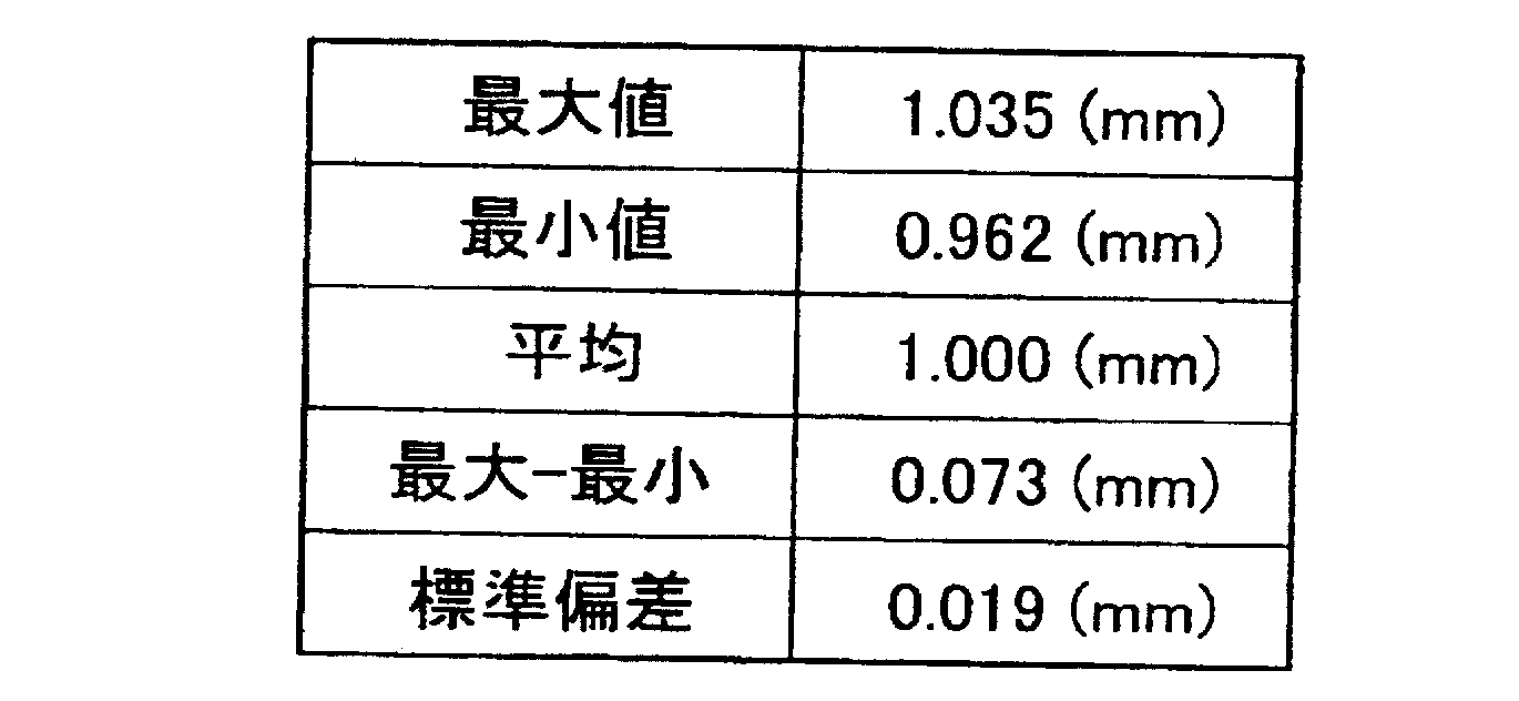
10、40…金型(型)、
1、11、201…下金型、
12、212…上金型、
3、13…凹凸パターン、
13a、13b、13c、13d、23a、23b、23c、23d…凸部、
14…内部、
14b…側面、
20、21…シート状材料、
23、30、130、230…成形品、
24…ダミーパターン、
24a、224a…ダミー凸部、
31…流路用パターン、
32…凹凸パターン部、
35…燃料電池用セパレータ。 3a, 3b, 3c, 24b, 24c, 24d, 24e ... concave portion,
10, 40 ... mold (mold),
1, 11, 201 ... lower mold,
12, 212 ... Upper mold,
3, 13 ... uneven pattern,
13a, 13b, 13c, 13d, 23a, 23b, 23c, 23d ... convex portions,
14 ... inside,
14b ... side,
20, 21 ... sheet-like material,
23, 30, 130, 230 ... moldings,
24 ... dummy pattern,
24a, 224a ... dummy convex parts,
31 ... Pattern for flow path,
32 ... uneven pattern part,
35 ... Fuel cell separator.
Claims (11)
- 少なくとも一方に凹部と凸部とからなる所定の凹凸パターンを有する一対の型を用いて、樹脂組成物と60~95体積%の充填材とを含むシート状材料を加圧することにより、前記凹凸パターンの転写された凹凸パターン部を有する成形品を形成する工程を備え、
前記一対の型として、内部に形成された凸部の合計体積と、前記凸部と前記内部の側面との間および前記凸部間に配置された凹部の合計容積との差を相殺するダミー凹部またはダミー凸部からなるダミーパターンが、前記内部に設けられたものを用いることを特徴とするシートプレス成形方法。 By pressing a sheet-like material containing a resin composition and 60 to 95% by volume of a filler using a pair of molds having a predetermined uneven pattern consisting of a concave portion and a convex portion in at least one of the concave and convex patterns, Comprising a step of forming a molded product having the transferred concavo-convex pattern portion,
As the pair of molds, a dummy recess that cancels out the difference between the total volume of the projections formed inside and the total volume of the recesses disposed between the projections and the side surfaces of the interior and between the projections. Alternatively, a sheet press molding method using a dummy pattern formed of dummy convex portions provided inside the dummy pattern. - 前記凸部の合計体積が前記凹部の合計容積よりも少なく、前記ダミーパターンがダミー凸部からなるものであることを特徴とする請求項1に記載のシートプレス成形方法。 The sheet press molding method according to claim 1, wherein the total volume of the convex portions is smaller than the total volume of the concave portions, and the dummy pattern is formed of dummy convex portions.
- 前記ダミーパターンが複数個所に設けられていることを特徴とする請求項1または請求項2に記載のシートプレス成形方法。 The sheet press molding method according to claim 1 or 2, wherein the dummy pattern is provided at a plurality of locations.
- 前記シート状材料が均一な厚みを有するものであることを特徴とする請求項1または請求項2に記載のシートプレス成形方法。 The sheet press molding method according to claim 1 or 2, wherein the sheet material has a uniform thickness.
- 前記充填材が炭素質材料であることを特徴とする請求項1または請求項2に記載のシートプレス成形方法。 The sheet press molding method according to claim 1 or 2, wherein the filler is a carbonaceous material.
- 前記ダミー凸部の高さが、前記凹凸パターンの凸部の高さと同じであることを特徴とする請求項2に記載のシートプレス成形方法。 The sheet press molding method according to claim 2, wherein the height of the dummy convex portion is the same as the height of the convex portion of the concavo-convex pattern.
- 少なくとも一方に凹部と凸部とからなる所定の凹凸パターンを有する一対の型を用いて、樹脂組成物と80~98質量%の炭素質材料とを含むシート状材料を加圧することにより、前記凹凸パターンの転写された流路用凹部を有する燃料電池用セパレータを形成する工程を備え、
前記一対の型として、内部に形成された凸部の合計体積と、前記凸部と前記内部の側面との間および前記凸部間に配置された凹部の合計容積との差を相殺するダミー凹部またはダミー凸部からなるダミーパターンが、前記内部に設けられたものを用いることを特徴とする燃料電池用セパレータの製造方法。 By pressing a sheet-like material containing a resin composition and 80 to 98% by mass of a carbonaceous material using a pair of molds having a predetermined concavo-convex pattern consisting of concave and convex portions on at least one side, the concavo-convex Comprising a step of forming a separator for a fuel cell having a recess for a flow path to which a pattern is transferred,
As the pair of molds, a dummy recess that cancels out the difference between the total volume of the projections formed inside and the total volume of the recesses disposed between the projections and the side surfaces of the interior and between the projections. Or the manufacturing method of the separator for fuel cells characterized by using the dummy pattern which consists of a dummy convex part provided in the said inside. - 前記凸部の合計体積が前記凹部の合計容積よりも少なく、前記ダミーパターンがダミー凸部からなるものであることを特徴とする請求項7に記載の燃料電池用セパレータの製造方法。 The method for manufacturing a fuel cell separator according to claim 7, wherein the total volume of the convex portions is smaller than the total volume of the concave portions, and the dummy pattern is formed of dummy convex portions.
- 前記ダミーパターンが複数の領域に設けられていることを特徴とする請求項7または請求項8に記載の燃料電池用セパレータの製造方法。 The method for manufacturing a separator for a fuel cell according to claim 7 or 8, wherein the dummy pattern is provided in a plurality of regions.
- 前記ダミーパターンが、前記燃料電池用セパレータのガス供給穴となる領域に対応する位置に設けられていることを特徴とする請求項7または請求項8に記載の燃料電池用セパレータの製造方法。 9. The method for manufacturing a fuel cell separator according to claim 7, wherein the dummy pattern is provided at a position corresponding to a region to be a gas supply hole of the fuel cell separator.
- 前記ダミー凸部の高さが、前記凹凸パターンの凸部の高さと同じであることを特徴とする請求項8に記載の燃料電池用セパレータの製造方法。 9. The method of manufacturing a fuel cell separator according to claim 8, wherein the height of the dummy convex portion is the same as the height of the convex portion of the concavo-convex pattern.
Priority Applications (6)
| Application Number | Priority Date | Filing Date | Title |
|---|---|---|---|
| CN201080015361.3A CN102365158B (en) | 2009-03-30 | 2010-03-29 | Sheet press molding method and method for manufacturing separator for fuel cell |
| US13/260,662 US9789634B2 (en) | 2009-03-30 | 2010-03-29 | Sheet press molding method and method of manufacturing fuel cell separator |
| JP2011508227A JP5548680B2 (en) | 2009-03-30 | 2010-03-29 | Sheet press forming method and fuel cell separator manufacturing method |
| KR1020117022621A KR101230807B1 (en) | 2009-03-30 | 2010-03-29 | Sheet press molding method and method for manufacturing separator for fuel cell |
| CA2756724A CA2756724C (en) | 2009-03-30 | 2010-03-29 | Sheet press molding method and method of manufacturing fuel cell separator |
| EP10761380.4A EP2415580B1 (en) | 2009-03-30 | 2010-03-29 | Sheet press molding method and method for manufacturing separator for fuel cell |
Applications Claiming Priority (2)
| Application Number | Priority Date | Filing Date | Title |
|---|---|---|---|
| JP2009082279 | 2009-03-30 | ||
| JP2009-082279 | 2009-03-30 |
Publications (1)
| Publication Number | Publication Date |
|---|---|
| WO2010116674A1 true WO2010116674A1 (en) | 2010-10-14 |
Family
ID=42935973
Family Applications (1)
| Application Number | Title | Priority Date | Filing Date |
|---|---|---|---|
| PCT/JP2010/002277 WO2010116674A1 (en) | 2009-03-30 | 2010-03-29 | Sheet press molding method and method for manufacturing separator for fuel cell |
Country Status (7)
| Country | Link |
|---|---|
| US (1) | US9789634B2 (en) |
| EP (1) | EP2415580B1 (en) |
| JP (1) | JP5548680B2 (en) |
| KR (1) | KR101230807B1 (en) |
| CN (1) | CN102365158B (en) |
| CA (1) | CA2756724C (en) |
| WO (1) | WO2010116674A1 (en) |
Cited By (4)
| Publication number | Priority date | Publication date | Assignee | Title |
|---|---|---|---|---|
| JP2014099346A (en) * | 2012-11-15 | 2014-05-29 | Toshiba Fuel Cell Power Systems Corp | Fuel cell stack and fuel cell system |
| KR101556836B1 (en) | 2011-06-30 | 2015-10-01 | 아사히 가세이 이-매터리얼즈 가부시키가이샤 | Convexo-concave microstructure transcription template |
| JP2016022603A (en) * | 2014-07-16 | 2016-02-08 | 株式会社日本製鋼所 | Molding die and molding method of microstructure |
| WO2016063983A1 (en) * | 2014-10-23 | 2016-04-28 | 昭和電工株式会社 | Fuel-cell porous separator, fuel cell, and method for manufacturing fuel-cell porous separator |
Families Citing this family (38)
| Publication number | Priority date | Publication date | Assignee | Title |
|---|---|---|---|---|
| US10464280B2 (en) | 2011-08-30 | 2019-11-05 | Shanghai Yanfeng Jinqiao Automotive Trim Systems Co. Ltd. | Trim component for vehicle interior |
| US8939745B2 (en) | 2011-08-30 | 2015-01-27 | Johnson Controls Technology Company | System and method for manufacturing a vehicle trim component via concurrent compression forming and injection molding |
| KR101625311B1 (en) | 2011-10-27 | 2016-05-27 | 갈모어, 인코포레이티드 | Composite graphene structures |
| US20130341874A1 (en) | 2012-06-26 | 2013-12-26 | Garlock Sealing Technologies Llc | Gasket Material, Gaskets, and Related Methods |
| US10093268B2 (en) | 2012-08-27 | 2018-10-09 | Shanghai Yanfeng Jinqiao Automotive Trim Systems Co. Ltd. | Trim component for vehicle interior |
| USD738473S1 (en) | 2012-10-19 | 2015-09-08 | Garlock Sealing Technologies, Llc | Gasket having raised sealing surface pattern |
| CA2903987C (en) | 2013-03-08 | 2018-05-01 | Richard Blair | Large scale oxidized graphene production for industrial applications |
| US10535443B2 (en) | 2013-03-08 | 2020-01-14 | Garmor Inc. | Graphene entrainment in a host |
| WO2015130280A1 (en) | 2014-02-27 | 2015-09-03 | Clearedge Power, Llc | Molding process for making fuel cell components |
| US9981408B2 (en) * | 2014-03-12 | 2018-05-29 | City University Of Hong Kong | Fabrication and replication of polymer optical waveguides |
| WO2016028756A1 (en) | 2014-08-18 | 2016-02-25 | Garmor, Inc. | Graphite oxide entrainment in cement and asphalt composite |
| KR102222115B1 (en) * | 2014-08-26 | 2021-03-03 | 삼성에스디아이 주식회사 | Molding apparatus and battery tray thereof |
| JP6277169B2 (en) | 2014-11-10 | 2018-02-07 | フタムラ化学株式会社 | Manufacturing method of flow path member for fuel cell |
| USD778142S1 (en) | 2015-03-11 | 2017-02-07 | Garlock Sealing Technologies, Llc | Gasket having raised sealing surface pattern |
| USD753274S1 (en) | 2015-03-11 | 2016-04-05 | Garlock Sealing Technologies, Llc | Gasket having raised sealing surface pattern |
| USD759218S1 (en) | 2015-03-11 | 2016-06-14 | Garlock Sealing Technologies, Llc | Gasket having raised sealing surface pattern |
| USD759217S1 (en) | 2015-03-11 | 2016-06-14 | Garlock Sealing Technologies, Llc | Gasket having raised sealing surface pattern |
| USD753275S1 (en) | 2015-03-11 | 2016-04-05 | Garlock Sealing Technologies, Llc | Gasket having raised sealing surface pattern |
| USD777016S1 (en) | 2015-03-11 | 2017-01-24 | Garlock Sealing Technologies, Llc | Gasket having raised sealing surface pattern |
| USD759219S1 (en) | 2015-03-11 | 2016-06-14 | Garlock Sealing Technologies, Llc | Gasket having raised sealing surface pattern |
| USD758728S1 (en) | 2015-03-11 | 2016-06-14 | Garlock Sealing Technologies, Llc | Gasket having raised sealing surface pattern |
| JP6522777B2 (en) | 2015-03-23 | 2019-05-29 | ガーマー インク.Garmor, Inc. | Design composite structure using graphene oxide |
| JP6563029B2 (en) | 2015-04-13 | 2019-08-21 | ガーマー インク.Garmor, Inc. | Graphite oxide reinforcing fiber in host such as concrete or asphalt |
| WO2016200469A1 (en) | 2015-06-09 | 2016-12-15 | Garmor Inc. | Graphite oxide and polyacrylonitrile based composite |
| US11038182B2 (en) | 2015-09-21 | 2021-06-15 | Garmor Inc. | Low-cost, high-performance composite bipolar plate |
| WO2017219139A1 (en) * | 2016-06-23 | 2017-12-28 | Fpinnovations | Wood pulp fiber- or cellulose filament-reinforced bulk molding compounds, composites, compositions and methods for preparation thereof |
| USD847746S1 (en) | 2016-10-07 | 2019-05-07 | Daramic, Llc | Battery separator |
| JP6994028B2 (en) | 2016-10-26 | 2022-01-14 | ガーマー インク. | Additive-coated particles for low-cost, high-performance materials |
| JP6642534B2 (en) * | 2017-08-04 | 2020-02-05 | トヨタ自動車株式会社 | Manufacturing method of fuel cell separator |
| JP6642535B2 (en) * | 2017-08-04 | 2020-02-05 | トヨタ自動車株式会社 | Manufacturing method of fuel cell separator |
| JP7040131B2 (en) * | 2018-03-02 | 2022-03-23 | トヨタ自動車株式会社 | Separator manufacturing method |
| WO2020006290A1 (en) | 2018-06-28 | 2020-01-02 | Shanghai Yanfeng Jinqiao Automotive Trim Systems Co. Ltd. | Vehicle trim component |
| JP7275539B2 (en) * | 2018-11-16 | 2023-05-18 | 日清紡ホールディングス株式会社 | Conductive metal-resin laminate and molded product thereof |
| US11316173B2 (en) * | 2019-07-02 | 2022-04-26 | Plug Power Inc. | Fuel cell stack |
| US11791061B2 (en) | 2019-09-12 | 2023-10-17 | Asbury Graphite North Carolina, Inc. | Conductive high strength extrudable ultra high molecular weight polymer graphene oxide composite |
| CN112372921A (en) * | 2020-11-14 | 2021-02-19 | 许子隆 | Preparation method of ultrahigh-power graphite electrode |
| CN115966709A (en) * | 2021-10-09 | 2023-04-14 | 罗伯特·博世有限公司 | Bipolar plate for fuel cell and method for preparing the same |
| JP7056796B1 (en) * | 2021-12-20 | 2022-04-19 | 日清紡ケミカル株式会社 | Precursor sheet for fuel cell separator and fuel cell separator |
Citations (11)
| Publication number | Priority date | Publication date | Assignee | Title |
|---|---|---|---|---|
| JPS60161144A (en) | 1984-01-11 | 1985-08-22 | 昭和電工株式会社 | Manufacture of carbon sheet |
| JPH08222241A (en) | 1995-02-09 | 1996-08-30 | Tokai Carbon Co Ltd | Manufacture of graphite member for solid high polymer fuel cell |
| JP2000021422A (en) | 1998-06-30 | 2000-01-21 | Toshiba Corp | Manufacture of separator for fuel cell, and the separator for fuel cell |
| JP2000082475A (en) | 1998-09-07 | 2000-03-21 | Nippon Pillar Packing Co Ltd | Separator for expansive graphite fuel cell and its manufacture |
| JP2001068128A (en) | 1999-06-24 | 2001-03-16 | Unitika Ltd | Separator for fuel cell and manufacture thereof |
| JP2003176327A (en) | 2001-08-06 | 2003-06-24 | Showa Denko Kk | Electroconductive curable resin composition |
| JP2005339874A (en) * | 2004-05-25 | 2005-12-08 | Dainippon Ink & Chem Inc | Die for manufacturing fuel cell separator and manufacturing method for fuel cell separator using die |
| JP2006252815A (en) * | 2005-03-08 | 2006-09-21 | Shin Etsu Polymer Co Ltd | Manufacturing method of separator for fuel cell, and separator for the fuel cell |
| JP2006294407A (en) * | 2005-04-11 | 2006-10-26 | Shin Etsu Polymer Co Ltd | Manufacturing method of separator for fuel cell and separator for fuel cell |
| JP2009006619A (en) * | 2007-06-29 | 2009-01-15 | Hitachi Ltd | Mold for nanoimprinting and recording medium |
| JP2009082279A (en) | 2007-09-28 | 2009-04-23 | Sammy Corp | Pinball game machine |
Family Cites Families (12)
| Publication number | Priority date | Publication date | Assignee | Title |
|---|---|---|---|---|
| US4737421A (en) | 1983-12-27 | 1988-04-12 | Showa Denko Kabushiki Kaisha | Method for producing a carbon sheet and a fuel cell separator |
| US4988583A (en) * | 1989-08-30 | 1991-01-29 | Her Majesty The Queen As Represented By The Minister Of National Defence Of Her Majesty's Canadian Government | Novel fuel cell fluid flow field plate |
| JP2001198921A (en) * | 2000-01-20 | 2001-07-24 | Nisshinbo Ind Inc | Mold for producing fuel cell separator |
| NL1014405C1 (en) * | 2000-02-17 | 2001-08-20 | Nedstack Holding B V | Method of Manufacture Polymer Electrolyte Fuel Cells. |
| JP2002110189A (en) * | 2000-09-29 | 2002-04-12 | Toshiba Corp | Separator for fuel cell and its manufacturing method and solid polymer fuel cell using the separator |
| WO2003014209A1 (en) | 2001-08-06 | 2003-02-20 | Showa Denko K. K. | Conductive curable resin composition and separator for fuel cell |
| DE10159008A1 (en) * | 2001-11-30 | 2003-06-12 | Schunk Kohlenstofftechnik Gmbh | Bipolar plate, pressing device and method for producing such |
| JP2004022207A (en) * | 2002-06-12 | 2004-01-22 | Mitsubishi Chemicals Corp | Method for press molding of powder, method of manufacturing fuel cell separator, and fuel cell separator |
| US8557448B2 (en) * | 2005-01-13 | 2013-10-15 | Toyota Jidosha Kabushiki Kaisha | Fuel cell and fuel cell separator |
| JP4580889B2 (en) * | 2006-04-05 | 2010-11-17 | 日本ピラー工業株式会社 | Fuel cell separator and method for producing the same |
| JP5068052B2 (en) * | 2006-09-29 | 2012-11-07 | 昭和電工株式会社 | FUEL CELL SEPARATOR, FUEL CELL CELL, FUEL CELL CELL UNIT, AND METHOD FOR PRODUCING FUEL CELL SEPARATOR AND FUEL CELL CELL UNIT |
| KR100882701B1 (en) * | 2007-06-19 | 2009-02-06 | 삼성에스디아이 주식회사 | Separator for fuel cell and its manufacturing method and fuel cell stack using the separator |
-
2010
- 2010-03-29 US US13/260,662 patent/US9789634B2/en not_active Expired - Fee Related
- 2010-03-29 EP EP10761380.4A patent/EP2415580B1/en not_active Not-in-force
- 2010-03-29 CA CA2756724A patent/CA2756724C/en not_active Expired - Fee Related
- 2010-03-29 KR KR1020117022621A patent/KR101230807B1/en active IP Right Grant
- 2010-03-29 JP JP2011508227A patent/JP5548680B2/en not_active Expired - Fee Related
- 2010-03-29 WO PCT/JP2010/002277 patent/WO2010116674A1/en active Application Filing
- 2010-03-29 CN CN201080015361.3A patent/CN102365158B/en not_active Expired - Fee Related
Patent Citations (11)
| Publication number | Priority date | Publication date | Assignee | Title |
|---|---|---|---|---|
| JPS60161144A (en) | 1984-01-11 | 1985-08-22 | 昭和電工株式会社 | Manufacture of carbon sheet |
| JPH08222241A (en) | 1995-02-09 | 1996-08-30 | Tokai Carbon Co Ltd | Manufacture of graphite member for solid high polymer fuel cell |
| JP2000021422A (en) | 1998-06-30 | 2000-01-21 | Toshiba Corp | Manufacture of separator for fuel cell, and the separator for fuel cell |
| JP2000082475A (en) | 1998-09-07 | 2000-03-21 | Nippon Pillar Packing Co Ltd | Separator for expansive graphite fuel cell and its manufacture |
| JP2001068128A (en) | 1999-06-24 | 2001-03-16 | Unitika Ltd | Separator for fuel cell and manufacture thereof |
| JP2003176327A (en) | 2001-08-06 | 2003-06-24 | Showa Denko Kk | Electroconductive curable resin composition |
| JP2005339874A (en) * | 2004-05-25 | 2005-12-08 | Dainippon Ink & Chem Inc | Die for manufacturing fuel cell separator and manufacturing method for fuel cell separator using die |
| JP2006252815A (en) * | 2005-03-08 | 2006-09-21 | Shin Etsu Polymer Co Ltd | Manufacturing method of separator for fuel cell, and separator for the fuel cell |
| JP2006294407A (en) * | 2005-04-11 | 2006-10-26 | Shin Etsu Polymer Co Ltd | Manufacturing method of separator for fuel cell and separator for fuel cell |
| JP2009006619A (en) * | 2007-06-29 | 2009-01-15 | Hitachi Ltd | Mold for nanoimprinting and recording medium |
| JP2009082279A (en) | 2007-09-28 | 2009-04-23 | Sammy Corp | Pinball game machine |
Non-Patent Citations (1)
| Title |
|---|
| SAITO, BANDO: "Fundamentals of Carbon Nanotubes", 1998, CORONA PUBLISHING CO., LTD., pages: 23 - 57 |
Cited By (4)
| Publication number | Priority date | Publication date | Assignee | Title |
|---|---|---|---|---|
| KR101556836B1 (en) | 2011-06-30 | 2015-10-01 | 아사히 가세이 이-매터리얼즈 가부시키가이샤 | Convexo-concave microstructure transcription template |
| JP2014099346A (en) * | 2012-11-15 | 2014-05-29 | Toshiba Fuel Cell Power Systems Corp | Fuel cell stack and fuel cell system |
| JP2016022603A (en) * | 2014-07-16 | 2016-02-08 | 株式会社日本製鋼所 | Molding die and molding method of microstructure |
| WO2016063983A1 (en) * | 2014-10-23 | 2016-04-28 | 昭和電工株式会社 | Fuel-cell porous separator, fuel cell, and method for manufacturing fuel-cell porous separator |
Also Published As
| Publication number | Publication date |
|---|---|
| JP5548680B2 (en) | 2014-07-16 |
| JPWO2010116674A1 (en) | 2012-10-18 |
| EP2415580A1 (en) | 2012-02-08 |
| EP2415580A4 (en) | 2016-07-27 |
| US9789634B2 (en) | 2017-10-17 |
| CN102365158A (en) | 2012-02-29 |
| KR20110130448A (en) | 2011-12-05 |
| CA2756724C (en) | 2013-12-10 |
| CA2756724A1 (en) | 2010-10-14 |
| US20120025420A1 (en) | 2012-02-02 |
| KR101230807B1 (en) | 2013-02-06 |
| CN102365158B (en) | 2014-02-26 |
| EP2415580B1 (en) | 2019-01-02 |
Similar Documents
| Publication | Publication Date | Title |
|---|---|---|
| JP5548680B2 (en) | Sheet press forming method and fuel cell separator manufacturing method | |
| WO2010116620A1 (en) | Sheet press molding method and method of fabricating fuel cell separators | |
| US7674402B2 (en) | Electroconductive resin composition and molded product thereof | |
| US7329698B2 (en) | Conductive curable resin composition and separator for fuel cell | |
| JP5567534B2 (en) | Conductive structure, method for producing the same, and separator for fuel cell | |
| JP2003176327A (en) | Electroconductive curable resin composition | |
| JP4889962B2 (en) | Conductive structure, method for producing the same, and separator for fuel cell | |
| JP4628143B2 (en) | Conductive resin composition and molded body thereof | |
| JP5025079B2 (en) | Conductive resin composition and molded body thereof | |
| KR20030036887A (en) | Conductive curable resin composition and separator for fuel cell | |
| JP2005129507A (en) | Graphitic powder for fuel cell separator, and fuel cell separator | |
| WO2015163253A1 (en) | Carbon current collector and fuel cell provided with same | |
| WO2005086177A1 (en) | Electroconductive resin composition and molded product thereof | |
| WO2016063982A1 (en) | Fuel-cell porous separator, fuel cell, and method for manufacturing fuel-cell porous separator | |
| WO2016063983A1 (en) | Fuel-cell porous separator, fuel cell, and method for manufacturing fuel-cell porous separator | |
| JP2011195618A (en) | Method for preparing electroconductive resin composition and fuel cell separator using the electroconductive resin composition |
Legal Events
| Date | Code | Title | Description |
|---|---|---|---|
| WWE | Wipo information: entry into national phase |
Ref document number: 201080015361.3 Country of ref document: CN |
|
| 121 | Ep: the epo has been informed by wipo that ep was designated in this application |
Ref document number: 10761380 Country of ref document: EP Kind code of ref document: A1 |
|
| ENP | Entry into the national phase |
Ref document number: 2011508227 Country of ref document: JP Kind code of ref document: A |
|
| WWE | Wipo information: entry into national phase |
Ref document number: 2010761380 Country of ref document: EP |
|
| WWE | Wipo information: entry into national phase |
Ref document number: 2756724 Country of ref document: CA |
|
| ENP | Entry into the national phase |
Ref document number: 20117022621 Country of ref document: KR Kind code of ref document: A |
|
| WWE | Wipo information: entry into national phase |
Ref document number: 13260662 Country of ref document: US |
|
| NENP | Non-entry into the national phase |
Ref country code: DE |