JP5548680B2 - Sheet press forming method and fuel cell separator manufacturing method - Google Patents
Sheet press forming method and fuel cell separator manufacturing method Download PDFInfo
- Publication number
- JP5548680B2 JP5548680B2 JP2011508227A JP2011508227A JP5548680B2 JP 5548680 B2 JP5548680 B2 JP 5548680B2 JP 2011508227 A JP2011508227 A JP 2011508227A JP 2011508227 A JP2011508227 A JP 2011508227A JP 5548680 B2 JP5548680 B2 JP 5548680B2
- Authority
- JP
- Japan
- Prior art keywords
- sheet
- dummy
- pattern
- convex
- fuel cell
- Prior art date
- Legal status (The legal status is an assumption and is not a legal conclusion. Google has not performed a legal analysis and makes no representation as to the accuracy of the status listed.)
- Expired - Fee Related
Links
- 238000000034 method Methods 0.000 title claims description 124
- 239000000446 fuel Substances 0.000 title claims description 121
- 238000004519 manufacturing process Methods 0.000 title claims description 44
- 239000000463 material Substances 0.000 claims description 109
- 239000003575 carbonaceous material Substances 0.000 claims description 67
- 238000000465 moulding Methods 0.000 claims description 67
- 239000000945 filler Substances 0.000 claims description 50
- 239000011342 resin composition Substances 0.000 claims description 40
- 238000003825 pressing Methods 0.000 claims description 28
- OKTJSMMVPCPJKN-UHFFFAOYSA-N Carbon Chemical compound [C] OKTJSMMVPCPJKN-UHFFFAOYSA-N 0.000 description 67
- 239000000047 product Substances 0.000 description 64
- 229910002804 graphite Inorganic materials 0.000 description 39
- 239000010439 graphite Substances 0.000 description 39
- ZOXJGFHDIHLPTG-UHFFFAOYSA-N Boron Chemical compound [B] ZOXJGFHDIHLPTG-UHFFFAOYSA-N 0.000 description 31
- 229910052796 boron Inorganic materials 0.000 description 31
- 239000007789 gas Substances 0.000 description 30
- 239000000843 powder Substances 0.000 description 21
- VNWKTOKETHGBQD-UHFFFAOYSA-N methane Chemical compound C VNWKTOKETHGBQD-UHFFFAOYSA-N 0.000 description 18
- 239000000571 coke Substances 0.000 description 15
- 229910021383 artificial graphite Inorganic materials 0.000 description 13
- 229920000049 Carbon (fiber) Polymers 0.000 description 12
- 229910052799 carbon Inorganic materials 0.000 description 12
- 239000004917 carbon fiber Substances 0.000 description 12
- 229910021382 natural graphite Inorganic materials 0.000 description 12
- 239000002245 particle Substances 0.000 description 12
- 239000002041 carbon nanotube Substances 0.000 description 11
- 229910021393 carbon nanotube Inorganic materials 0.000 description 11
- 239000000835 fiber Substances 0.000 description 11
- 230000000052 comparative effect Effects 0.000 description 9
- 239000000203 mixture Substances 0.000 description 9
- 238000010586 diagram Methods 0.000 description 8
- XLYOFNOQVPJJNP-UHFFFAOYSA-N water Substances O XLYOFNOQVPJJNP-UHFFFAOYSA-N 0.000 description 8
- 238000005087 graphitization Methods 0.000 description 7
- 238000012856 packing Methods 0.000 description 7
- -1 polyethylene Polymers 0.000 description 7
- 238000010298 pulverizing process Methods 0.000 description 7
- 235000011835 quiches Nutrition 0.000 description 7
- 229920005989 resin Polymers 0.000 description 7
- 239000011347 resin Substances 0.000 description 7
- XKRFYHLGVUSROY-UHFFFAOYSA-N Argon Chemical group [Ar] XKRFYHLGVUSROY-UHFFFAOYSA-N 0.000 description 6
- 229910003481 amorphous carbon Inorganic materials 0.000 description 6
- 239000002134 carbon nanofiber Substances 0.000 description 6
- 238000002156 mixing Methods 0.000 description 6
- 239000012298 atmosphere Substances 0.000 description 5
- 239000006229 carbon black Substances 0.000 description 5
- 239000013078 crystal Substances 0.000 description 5
- 238000009792 diffusion process Methods 0.000 description 5
- 238000009826 distribution Methods 0.000 description 5
- 230000002093 peripheral effect Effects 0.000 description 5
- 239000011295 pitch Substances 0.000 description 5
- 229920002239 polyacrylonitrile Polymers 0.000 description 5
- UFHFLCQGNIYNRP-UHFFFAOYSA-N Hydrogen Chemical compound [H][H] UFHFLCQGNIYNRP-UHFFFAOYSA-N 0.000 description 4
- VYPSYNLAJGMNEJ-UHFFFAOYSA-N Silicium dioxide Chemical compound O=[Si]=O VYPSYNLAJGMNEJ-UHFFFAOYSA-N 0.000 description 4
- INAHAJYZKVIDIZ-UHFFFAOYSA-N boron carbide Chemical compound B12B3B4C32B41 INAHAJYZKVIDIZ-UHFFFAOYSA-N 0.000 description 4
- 239000003054 catalyst Substances 0.000 description 4
- 238000011156 evaluation Methods 0.000 description 4
- 230000005484 gravity Effects 0.000 description 4
- 238000010438 heat treatment Methods 0.000 description 4
- 239000003345 natural gas Substances 0.000 description 4
- 239000005011 phenolic resin Substances 0.000 description 4
- 238000010248 power generation Methods 0.000 description 4
- 239000002994 raw material Substances 0.000 description 4
- QAOWNCQODCNURD-UHFFFAOYSA-N sulfuric acid Substances OS(O)(=O)=O QAOWNCQODCNURD-UHFFFAOYSA-N 0.000 description 4
- 229920001187 thermosetting polymer Polymers 0.000 description 4
- 229910052580 B4C Inorganic materials 0.000 description 3
- UHOVQNZJYSORNB-UHFFFAOYSA-N Benzene Chemical compound C1=CC=CC=C1 UHOVQNZJYSORNB-UHFFFAOYSA-N 0.000 description 3
- XMWRBQBLMFGWIX-UHFFFAOYSA-N C60 fullerene Chemical compound C12=C3C(C4=C56)=C7C8=C5C5=C9C%10=C6C6=C4C1=C1C4=C6C6=C%10C%10=C9C9=C%11C5=C8C5=C8C7=C3C3=C7C2=C1C1=C2C4=C6C4=C%10C6=C9C9=C%11C5=C5C8=C3C3=C7C1=C1C2=C4C6=C2C9=C5C3=C12 XMWRBQBLMFGWIX-UHFFFAOYSA-N 0.000 description 3
- 239000004698 Polyethylene Substances 0.000 description 3
- YXFVVABEGXRONW-UHFFFAOYSA-N Toluene Chemical compound CC1=CC=CC=C1 YXFVVABEGXRONW-UHFFFAOYSA-N 0.000 description 3
- 229910052786 argon Inorganic materials 0.000 description 3
- 238000006243 chemical reaction Methods 0.000 description 3
- 230000000694 effects Effects 0.000 description 3
- 229920001971 elastomer Polymers 0.000 description 3
- 238000010304 firing Methods 0.000 description 3
- 239000002737 fuel gas Substances 0.000 description 3
- 229910003472 fullerene Inorganic materials 0.000 description 3
- 239000001257 hydrogen Substances 0.000 description 3
- 229910052739 hydrogen Inorganic materials 0.000 description 3
- 239000011261 inert gas Substances 0.000 description 3
- 229910052751 metal Inorganic materials 0.000 description 3
- 239000002184 metal Substances 0.000 description 3
- 239000007769 metal material Substances 0.000 description 3
- 238000012986 modification Methods 0.000 description 3
- 230000004048 modification Effects 0.000 description 3
- 230000001590 oxidative effect Effects 0.000 description 3
- 229920000573 polyethylene Polymers 0.000 description 3
- 239000005518 polymer electrolyte Substances 0.000 description 3
- 238000005096 rolling process Methods 0.000 description 3
- 239000002109 single walled nanotube Substances 0.000 description 3
- 239000007787 solid Substances 0.000 description 3
- 238000005979 thermal decomposition reaction Methods 0.000 description 3
- 239000004215 Carbon black (E152) Substances 0.000 description 2
- UQSXHKLRYXJYBZ-UHFFFAOYSA-N Iron oxide Chemical compound [Fe]=O UQSXHKLRYXJYBZ-UHFFFAOYSA-N 0.000 description 2
- GRYLNZFGIOXLOG-UHFFFAOYSA-N Nitric acid Chemical compound O[N+]([O-])=O GRYLNZFGIOXLOG-UHFFFAOYSA-N 0.000 description 2
- 239000004743 Polypropylene Substances 0.000 description 2
- 239000004793 Polystyrene Substances 0.000 description 2
- XUIMIQQOPSSXEZ-UHFFFAOYSA-N Silicon Chemical compound [Si] XUIMIQQOPSSXEZ-UHFFFAOYSA-N 0.000 description 2
- 241000376294 Tringa semipalmata Species 0.000 description 2
- 239000000654 additive Substances 0.000 description 2
- 229910052782 aluminium Inorganic materials 0.000 description 2
- XAGFODPZIPBFFR-UHFFFAOYSA-N aluminium Chemical compound [Al] XAGFODPZIPBFFR-UHFFFAOYSA-N 0.000 description 2
- PNEYBMLMFCGWSK-UHFFFAOYSA-N aluminium oxide Inorganic materials [O-2].[O-2].[O-2].[Al+3].[Al+3] PNEYBMLMFCGWSK-UHFFFAOYSA-N 0.000 description 2
- QVGXLLKOCUKJST-UHFFFAOYSA-N atomic oxygen Chemical compound [O] QVGXLLKOCUKJST-UHFFFAOYSA-N 0.000 description 2
- 229910052790 beryllium Inorganic materials 0.000 description 2
- ATBAMAFKBVZNFJ-UHFFFAOYSA-N beryllium atom Chemical compound [Be] ATBAMAFKBVZNFJ-UHFFFAOYSA-N 0.000 description 2
- 239000011230 binding agent Substances 0.000 description 2
- 150000001639 boron compounds Chemical class 0.000 description 2
- 150000001721 carbon Chemical group 0.000 description 2
- 239000003795 chemical substances by application Substances 0.000 description 2
- 238000009694 cold isostatic pressing Methods 0.000 description 2
- 229920001940 conductive polymer Polymers 0.000 description 2
- 238000005520 cutting process Methods 0.000 description 2
- 230000007547 defect Effects 0.000 description 2
- 239000000806 elastomer Substances 0.000 description 2
- 239000010419 fine particle Substances 0.000 description 2
- 229930195733 hydrocarbon Natural products 0.000 description 2
- 150000002430 hydrocarbons Chemical class 0.000 description 2
- 239000012535 impurity Substances 0.000 description 2
- 239000003999 initiator Substances 0.000 description 2
- 230000001788 irregular Effects 0.000 description 2
- 239000002048 multi walled nanotube Substances 0.000 description 2
- 229910017604 nitric acid Inorganic materials 0.000 description 2
- 239000003921 oil Substances 0.000 description 2
- 239000001301 oxygen Substances 0.000 description 2
- 229910052760 oxygen Inorganic materials 0.000 description 2
- 229920002589 poly(vinylethylene) polymer Polymers 0.000 description 2
- 229920001748 polybutylene Polymers 0.000 description 2
- 229920001195 polyisoprene Polymers 0.000 description 2
- 229920005597 polymer membrane Polymers 0.000 description 2
- 229920001155 polypropylene Polymers 0.000 description 2
- 229920002223 polystyrene Polymers 0.000 description 2
- 238000000926 separation method Methods 0.000 description 2
- 229910052710 silicon Inorganic materials 0.000 description 2
- 239000010703 silicon Substances 0.000 description 2
- 239000000377 silicon dioxide Substances 0.000 description 2
- 239000000126 substance Substances 0.000 description 2
- 229920005992 thermoplastic resin Polymers 0.000 description 2
- 238000007088 Archimedes method Methods 0.000 description 1
- MHAJPDPJQMAIIY-UHFFFAOYSA-N Hydrogen peroxide Chemical compound OO MHAJPDPJQMAIIY-UHFFFAOYSA-N 0.000 description 1
- 229920000106 Liquid crystal polymer Polymers 0.000 description 1
- 239000004977 Liquid-crystal polymers (LCPs) Substances 0.000 description 1
- 229910000805 Pig iron Inorganic materials 0.000 description 1
- 239000004696 Poly ether ether ketone Substances 0.000 description 1
- 239000004734 Polyphenylene sulfide Substances 0.000 description 1
- GWEVSGVZZGPLCZ-UHFFFAOYSA-N Titan oxide Chemical compound O=[Ti]=O GWEVSGVZZGPLCZ-UHFFFAOYSA-N 0.000 description 1
- 239000012963 UV stabilizer Substances 0.000 description 1
- OMOVVBIIQSXZSZ-UHFFFAOYSA-N [6-(4-acetyloxy-5,9a-dimethyl-2,7-dioxo-4,5a,6,9-tetrahydro-3h-pyrano[3,4-b]oxepin-5-yl)-5-formyloxy-3-(furan-3-yl)-3a-methyl-7-methylidene-1a,2,3,4,5,6-hexahydroindeno[1,7a-b]oxiren-4-yl] 2-hydroxy-3-methylpentanoate Chemical compound CC12C(OC(=O)C(O)C(C)CC)C(OC=O)C(C3(C)C(CC(=O)OC4(C)COC(=O)CC43)OC(C)=O)C(=C)C32OC3CC1C=1C=COC=1 OMOVVBIIQSXZSZ-UHFFFAOYSA-N 0.000 description 1
- 239000006230 acetylene black Substances 0.000 description 1
- HSFWRNGVRCDJHI-UHFFFAOYSA-N alpha-acetylene Natural products C#C HSFWRNGVRCDJHI-UHFFFAOYSA-N 0.000 description 1
- 239000003963 antioxidant agent Substances 0.000 description 1
- 239000007864 aqueous solution Substances 0.000 description 1
- 238000001241 arc-discharge method Methods 0.000 description 1
- 239000011324 bead Substances 0.000 description 1
- 230000015572 biosynthetic process Effects 0.000 description 1
- 235000008429 bread Nutrition 0.000 description 1
- 239000006227 byproduct Substances 0.000 description 1
- 125000004432 carbon atom Chemical group C* 0.000 description 1
- 239000011300 coal pitch Substances 0.000 description 1
- 239000011280 coal tar Substances 0.000 description 1
- 238000002485 combustion reaction Methods 0.000 description 1
- 150000001875 compounds Chemical class 0.000 description 1
- 238000000748 compression moulding Methods 0.000 description 1
- 230000007797 corrosion Effects 0.000 description 1
- 238000005260 corrosion Methods 0.000 description 1
- 230000007423 decrease Effects 0.000 description 1
- 230000003247 decreasing effect Effects 0.000 description 1
- 238000013461 design Methods 0.000 description 1
- 238000007865 diluting Methods 0.000 description 1
- 239000012153 distilled water Substances 0.000 description 1
- 230000005611 electricity Effects 0.000 description 1
- 238000005868 electrolysis reaction Methods 0.000 description 1
- 239000003792 electrolyte Substances 0.000 description 1
- 238000005516 engineering process Methods 0.000 description 1
- 230000007613 environmental effect Effects 0.000 description 1
- 125000002534 ethynyl group Chemical group [H]C#C* 0.000 description 1
- 238000001704 evaporation Methods 0.000 description 1
- KTWOOEGAPBSYNW-UHFFFAOYSA-N ferrocene Chemical compound [Fe+2].C=1C=C[CH-]C=1.C=1C=C[CH-]C=1 KTWOOEGAPBSYNW-UHFFFAOYSA-N 0.000 description 1
- 238000011049 filling Methods 0.000 description 1
- 239000000295 fuel oil Substances 0.000 description 1
- 239000003365 glass fiber Substances 0.000 description 1
- 230000009477 glass transition Effects 0.000 description 1
- 238000005469 granulation Methods 0.000 description 1
- 230000003179 granulation Effects 0.000 description 1
- 238000001027 hydrothermal synthesis Methods 0.000 description 1
- 238000010191 image analysis Methods 0.000 description 1
- 238000007654 immersion Methods 0.000 description 1
- 230000006698 induction Effects 0.000 description 1
- 230000001939 inductive effect Effects 0.000 description 1
- 238000001095 inductively coupled plasma mass spectrometry Methods 0.000 description 1
- 238000009830 intercalation Methods 0.000 description 1
- 230000002687 intercalation Effects 0.000 description 1
- 239000003273 ketjen black Substances 0.000 description 1
- 238000004898 kneading Methods 0.000 description 1
- 239000000314 lubricant Substances 0.000 description 1
- 238000004949 mass spectrometry Methods 0.000 description 1
- 238000005259 measurement Methods 0.000 description 1
- 238000002844 melting Methods 0.000 description 1
- 230000008018 melting Effects 0.000 description 1
- 239000012528 membrane Substances 0.000 description 1
- 229910044991 metal oxide Inorganic materials 0.000 description 1
- 150000004706 metal oxides Chemical class 0.000 description 1
- 239000011259 mixed solution Substances 0.000 description 1
- 239000003607 modifier Substances 0.000 description 1
- 239000006082 mold release agent Substances 0.000 description 1
- 239000012778 molding material Substances 0.000 description 1
- 239000000178 monomer Substances 0.000 description 1
- 229920003986 novolac Polymers 0.000 description 1
- 239000004843 novolac epoxy resin Substances 0.000 description 1
- 150000002894 organic compounds Chemical class 0.000 description 1
- 239000007800 oxidant agent Substances 0.000 description 1
- 230000003647 oxidation Effects 0.000 description 1
- 238000007254 oxidation reaction Methods 0.000 description 1
- 238000005453 pelletization Methods 0.000 description 1
- 230000000149 penetrating effect Effects 0.000 description 1
- VLTRZXGMWDSKGL-UHFFFAOYSA-N perchloric acid Chemical compound OCl(=O)(=O)=O VLTRZXGMWDSKGL-UHFFFAOYSA-N 0.000 description 1
- 239000011301 petroleum pitch Substances 0.000 description 1
- 230000000704 physical effect Effects 0.000 description 1
- 238000001637 plasma atomic emission spectroscopy Methods 0.000 description 1
- 229920003050 poly-cycloolefin Polymers 0.000 description 1
- 229920002530 polyetherether ketone Polymers 0.000 description 1
- 239000011116 polymethylpentene Substances 0.000 description 1
- 229920000306 polymethylpentene Polymers 0.000 description 1
- 229920001955 polyphenylene ether Polymers 0.000 description 1
- 229920000069 polyphenylene sulfide Polymers 0.000 description 1
- 238000012545 processing Methods 0.000 description 1
- 238000000746 purification Methods 0.000 description 1
- 239000012495 reaction gas Substances 0.000 description 1
- 230000001105 regulatory effect Effects 0.000 description 1
- 239000005871 repellent Substances 0.000 description 1
- 230000002940 repellent Effects 0.000 description 1
- 239000005060 rubber Substances 0.000 description 1
- 238000000790 scattering method Methods 0.000 description 1
- 238000004062 sedimentation Methods 0.000 description 1
- 238000007873 sieving Methods 0.000 description 1
- 238000005245 sintering Methods 0.000 description 1
- 239000002893 slag Substances 0.000 description 1
- 239000000243 solution Substances 0.000 description 1
- 238000003756 stirring Methods 0.000 description 1
- 238000003860 storage Methods 0.000 description 1
- 238000006467 substitution reaction Methods 0.000 description 1
- 239000004094 surface-active agent Substances 0.000 description 1
- 230000008961 swelling Effects 0.000 description 1
- 239000002562 thickening agent Substances 0.000 description 1
- OGIDPMRJRNCKJF-UHFFFAOYSA-N titanium oxide Inorganic materials [Ti]=O OGIDPMRJRNCKJF-UHFFFAOYSA-N 0.000 description 1
- 229910052723 transition metal Inorganic materials 0.000 description 1
- 150000003624 transition metals Chemical class 0.000 description 1
- GPRLSGONYQIRFK-MNYXATJNSA-N triton Chemical compound [3H+] GPRLSGONYQIRFK-MNYXATJNSA-N 0.000 description 1
- 238000000108 ultra-filtration Methods 0.000 description 1
Images


Classifications
-
- B—PERFORMING OPERATIONS; TRANSPORTING
- B29—WORKING OF PLASTICS; WORKING OF SUBSTANCES IN A PLASTIC STATE IN GENERAL
- B29C—SHAPING OR JOINING OF PLASTICS; SHAPING OF MATERIAL IN A PLASTIC STATE, NOT OTHERWISE PROVIDED FOR; AFTER-TREATMENT OF THE SHAPED PRODUCTS, e.g. REPAIRING
- B29C43/00—Compression moulding, i.e. applying external pressure to flow the moulding material; Apparatus therefor
- B29C43/02—Compression moulding, i.e. applying external pressure to flow the moulding material; Apparatus therefor of articles of definite length, i.e. discrete articles
- B29C43/021—Compression moulding, i.e. applying external pressure to flow the moulding material; Apparatus therefor of articles of definite length, i.e. discrete articles characterised by the shape of the surface
-
- B—PERFORMING OPERATIONS; TRANSPORTING
- B29—WORKING OF PLASTICS; WORKING OF SUBSTANCES IN A PLASTIC STATE IN GENERAL
- B29C—SHAPING OR JOINING OF PLASTICS; SHAPING OF MATERIAL IN A PLASTIC STATE, NOT OTHERWISE PROVIDED FOR; AFTER-TREATMENT OF THE SHAPED PRODUCTS, e.g. REPAIRING
- B29C43/00—Compression moulding, i.e. applying external pressure to flow the moulding material; Apparatus therefor
- B29C43/02—Compression moulding, i.e. applying external pressure to flow the moulding material; Apparatus therefor of articles of definite length, i.e. discrete articles
-
- B—PERFORMING OPERATIONS; TRANSPORTING
- B29—WORKING OF PLASTICS; WORKING OF SUBSTANCES IN A PLASTIC STATE IN GENERAL
- B29C—SHAPING OR JOINING OF PLASTICS; SHAPING OF MATERIAL IN A PLASTIC STATE, NOT OTHERWISE PROVIDED FOR; AFTER-TREATMENT OF THE SHAPED PRODUCTS, e.g. REPAIRING
- B29C43/00—Compression moulding, i.e. applying external pressure to flow the moulding material; Apparatus therefor
- B29C43/32—Component parts, details or accessories; Auxiliary operations
- B29C43/36—Moulds for making articles of definite length, i.e. discrete articles
-
- B—PERFORMING OPERATIONS; TRANSPORTING
- B29—WORKING OF PLASTICS; WORKING OF SUBSTANCES IN A PLASTIC STATE IN GENERAL
- B29C—SHAPING OR JOINING OF PLASTICS; SHAPING OF MATERIAL IN A PLASTIC STATE, NOT OTHERWISE PROVIDED FOR; AFTER-TREATMENT OF THE SHAPED PRODUCTS, e.g. REPAIRING
- B29C59/00—Surface shaping of articles, e.g. embossing; Apparatus therefor
- B29C59/02—Surface shaping of articles, e.g. embossing; Apparatus therefor by mechanical means, e.g. pressing
-
- H—ELECTRICITY
- H01—ELECTRIC ELEMENTS
- H01M—PROCESSES OR MEANS, e.g. BATTERIES, FOR THE DIRECT CONVERSION OF CHEMICAL ENERGY INTO ELECTRICAL ENERGY
- H01M8/00—Fuel cells; Manufacture thereof
- H01M8/02—Details
-
- H—ELECTRICITY
- H01—ELECTRIC ELEMENTS
- H01M—PROCESSES OR MEANS, e.g. BATTERIES, FOR THE DIRECT CONVERSION OF CHEMICAL ENERGY INTO ELECTRICAL ENERGY
- H01M8/00—Fuel cells; Manufacture thereof
- H01M8/02—Details
- H01M8/0202—Collectors; Separators, e.g. bipolar separators; Interconnectors
- H01M8/0204—Non-porous and characterised by the material
- H01M8/0213—Gas-impermeable carbon-containing materials
-
- H—ELECTRICITY
- H01—ELECTRIC ELEMENTS
- H01M—PROCESSES OR MEANS, e.g. BATTERIES, FOR THE DIRECT CONVERSION OF CHEMICAL ENERGY INTO ELECTRICAL ENERGY
- H01M8/00—Fuel cells; Manufacture thereof
- H01M8/02—Details
- H01M8/0202—Collectors; Separators, e.g. bipolar separators; Interconnectors
- H01M8/0204—Non-porous and characterised by the material
- H01M8/0221—Organic resins; Organic polymers
-
- H—ELECTRICITY
- H01—ELECTRIC ELEMENTS
- H01M—PROCESSES OR MEANS, e.g. BATTERIES, FOR THE DIRECT CONVERSION OF CHEMICAL ENERGY INTO ELECTRICAL ENERGY
- H01M8/00—Fuel cells; Manufacture thereof
- H01M8/02—Details
- H01M8/0202—Collectors; Separators, e.g. bipolar separators; Interconnectors
- H01M8/0204—Non-porous and characterised by the material
- H01M8/0223—Composites
- H01M8/0226—Composites in the form of mixtures
-
- H—ELECTRICITY
- H01—ELECTRIC ELEMENTS
- H01M—PROCESSES OR MEANS, e.g. BATTERIES, FOR THE DIRECT CONVERSION OF CHEMICAL ENERGY INTO ELECTRICAL ENERGY
- H01M8/00—Fuel cells; Manufacture thereof
- H01M8/02—Details
- H01M8/0202—Collectors; Separators, e.g. bipolar separators; Interconnectors
- H01M8/0258—Collectors; Separators, e.g. bipolar separators; Interconnectors characterised by the configuration of channels, e.g. by the flow field of the reactant or coolant
- H01M8/026—Collectors; Separators, e.g. bipolar separators; Interconnectors characterised by the configuration of channels, e.g. by the flow field of the reactant or coolant characterised by grooves, e.g. their pitch or depth
-
- B—PERFORMING OPERATIONS; TRANSPORTING
- B29—WORKING OF PLASTICS; WORKING OF SUBSTANCES IN A PLASTIC STATE IN GENERAL
- B29C—SHAPING OR JOINING OF PLASTICS; SHAPING OF MATERIAL IN A PLASTIC STATE, NOT OTHERWISE PROVIDED FOR; AFTER-TREATMENT OF THE SHAPED PRODUCTS, e.g. REPAIRING
- B29C43/00—Compression moulding, i.e. applying external pressure to flow the moulding material; Apparatus therefor
- B29C43/02—Compression moulding, i.e. applying external pressure to flow the moulding material; Apparatus therefor of articles of definite length, i.e. discrete articles
- B29C43/021—Compression moulding, i.e. applying external pressure to flow the moulding material; Apparatus therefor of articles of definite length, i.e. discrete articles characterised by the shape of the surface
- B29C2043/023—Compression moulding, i.e. applying external pressure to flow the moulding material; Apparatus therefor of articles of definite length, i.e. discrete articles characterised by the shape of the surface having a plurality of grooves
- B29C2043/025—Compression moulding, i.e. applying external pressure to flow the moulding material; Apparatus therefor of articles of definite length, i.e. discrete articles characterised by the shape of the surface having a plurality of grooves forming a microstructure, i.e. fine patterning
-
- B—PERFORMING OPERATIONS; TRANSPORTING
- B29—WORKING OF PLASTICS; WORKING OF SUBSTANCES IN A PLASTIC STATE IN GENERAL
- B29K—INDEXING SCHEME ASSOCIATED WITH SUBCLASSES B29B, B29C OR B29D, RELATING TO MOULDING MATERIALS OR TO MATERIALS FOR MOULDS, REINFORCEMENTS, FILLERS OR PREFORMED PARTS, e.g. INSERTS
- B29K2105/00—Condition, form or state of moulded material or of the material to be shaped
- B29K2105/06—Condition, form or state of moulded material or of the material to be shaped containing reinforcements, fillers or inserts
- B29K2105/16—Fillers
-
- B—PERFORMING OPERATIONS; TRANSPORTING
- B29—WORKING OF PLASTICS; WORKING OF SUBSTANCES IN A PLASTIC STATE IN GENERAL
- B29K—INDEXING SCHEME ASSOCIATED WITH SUBCLASSES B29B, B29C OR B29D, RELATING TO MOULDING MATERIALS OR TO MATERIALS FOR MOULDS, REINFORCEMENTS, FILLERS OR PREFORMED PARTS, e.g. INSERTS
- B29K2105/00—Condition, form or state of moulded material or of the material to be shaped
- B29K2105/25—Solid
- B29K2105/253—Preform
- B29K2105/256—Sheets, plates, blanks or films
-
- B—PERFORMING OPERATIONS; TRANSPORTING
- B29—WORKING OF PLASTICS; WORKING OF SUBSTANCES IN A PLASTIC STATE IN GENERAL
- B29L—INDEXING SCHEME ASSOCIATED WITH SUBCLASS B29C, RELATING TO PARTICULAR ARTICLES
- B29L2031/00—Other particular articles
- B29L2031/34—Electrical apparatus, e.g. sparking plugs or parts thereof
- B29L2031/3468—Batteries, accumulators or fuel cells
-
- H—ELECTRICITY
- H01—ELECTRIC ELEMENTS
- H01M—PROCESSES OR MEANS, e.g. BATTERIES, FOR THE DIRECT CONVERSION OF CHEMICAL ENERGY INTO ELECTRICAL ENERGY
- H01M8/00—Fuel cells; Manufacture thereof
- H01M8/10—Fuel cells with solid electrolytes
- H01M2008/1095—Fuel cells with polymeric electrolytes
-
- Y—GENERAL TAGGING OF NEW TECHNOLOGICAL DEVELOPMENTS; GENERAL TAGGING OF CROSS-SECTIONAL TECHNOLOGIES SPANNING OVER SEVERAL SECTIONS OF THE IPC; TECHNICAL SUBJECTS COVERED BY FORMER USPC CROSS-REFERENCE ART COLLECTIONS [XRACs] AND DIGESTS
- Y02—TECHNOLOGIES OR APPLICATIONS FOR MITIGATION OR ADAPTATION AGAINST CLIMATE CHANGE
- Y02E—REDUCTION OF GREENHOUSE GAS [GHG] EMISSIONS, RELATED TO ENERGY GENERATION, TRANSMISSION OR DISTRIBUTION
- Y02E60/00—Enabling technologies; Technologies with a potential or indirect contribution to GHG emissions mitigation
- Y02E60/30—Hydrogen technology
- Y02E60/50—Fuel cells
-
- Y—GENERAL TAGGING OF NEW TECHNOLOGICAL DEVELOPMENTS; GENERAL TAGGING OF CROSS-SECTIONAL TECHNOLOGIES SPANNING OVER SEVERAL SECTIONS OF THE IPC; TECHNICAL SUBJECTS COVERED BY FORMER USPC CROSS-REFERENCE ART COLLECTIONS [XRACs] AND DIGESTS
- Y02—TECHNOLOGIES OR APPLICATIONS FOR MITIGATION OR ADAPTATION AGAINST CLIMATE CHANGE
- Y02P—CLIMATE CHANGE MITIGATION TECHNOLOGIES IN THE PRODUCTION OR PROCESSING OF GOODS
- Y02P70/00—Climate change mitigation technologies in the production process for final industrial or consumer products
- Y02P70/50—Manufacturing or production processes characterised by the final manufactured product
Landscapes
- Engineering & Computer Science (AREA)
- Chemical & Material Sciences (AREA)
- Manufacturing & Machinery (AREA)
- Life Sciences & Earth Sciences (AREA)
- Sustainable Development (AREA)
- Sustainable Energy (AREA)
- Chemical Kinetics & Catalysis (AREA)
- Electrochemistry (AREA)
- General Chemical & Material Sciences (AREA)
- Mechanical Engineering (AREA)
- Composite Materials (AREA)
- Fuel Cell (AREA)
- Moulds For Moulding Plastics Or The Like (AREA)
- Casting Or Compression Moulding Of Plastics Or The Like (AREA)
Description
本発明は、シートプレス成形方法および燃料電池用セパレータの製造方法に関する。さらに詳しくは、充填材(フィラー)を高濃度で含有する樹脂組成物シートを用いるシートプレス成形方法および炭素質材料を高濃度で含有する樹脂組成物シートを用いる燃料電池用セパレータの製造方法に関する。
本願は、2009年3月30日に、日本に出願された特願2009−082279号に基づき優先権を主張し、その内容をここに援用する。The present invention relates to a sheet press molding method and a method for manufacturing a fuel cell separator. More specifically, the present invention relates to a sheet press molding method using a resin composition sheet containing a filler (filler) at a high concentration and a method for producing a fuel cell separator using a resin composition sheet containing a carbonaceous material at a high concentration.
This application claims priority on March 30, 2009 based on Japanese Patent Application No. 2009-082279 for which it applied to Japan, and uses the content here.
近年、薄肉かつ大面積製品の成形加工方法として、シートプレス成形方法が注目されており、例えば燃料電池用セパレータの成形加工などに用いられている。以下、燃料電池用セパレータの製造方法を例に挙げて、シートプレス成形方法について説明する。 In recent years, a sheet press molding method has attracted attention as a molding method for thin-walled and large-area products, and is used for molding a fuel cell separator, for example. Hereinafter, the sheet press molding method will be described with reference to an example of a method for manufacturing a fuel cell separator.
燃料電池は、水素と酸素を利用した水の電気分解の逆反応で発電し、水以外の排出物が出ないクリーンな発電装置であるため、環境問題、エネルギー問題の観点から注目されている。燃料電池は、用いられる電解質の種類に応じて数種類に分類される。燃料電池の中でも、低温で作動する固体高分子型の燃料電池は、自動車や民生用として最も有望とされている。この燃料電池は、通常、固体高分子電解質として作用する固体高分子膜と、固体高分子膜を挟持する一対の触媒を担持させたガス拡散電極とを一体化してなる膜電極接合体(MEA:Membrane-Electrode Assembly)と、MEAの外側から挟持して燃料ガスと酸化性ガスとを分離するセパレータとを有する単セルを基本単位としている。そして、この単セルを多数個積層することによって、燃料電池において高出力の発電が達成できる。 A fuel cell is a clean power generation device that generates electricity by the reverse reaction of water electrolysis using hydrogen and oxygen and does not emit any other substances than water, and is therefore attracting attention from the viewpoints of environmental problems and energy problems. Fuel cells are classified into several types depending on the type of electrolyte used. Among fuel cells, a polymer electrolyte fuel cell that operates at a low temperature is considered most promising for automobiles and consumer use. This fuel cell is usually a membrane electrode assembly (MEA :) formed by integrating a solid polymer membrane acting as a solid polymer electrolyte and a gas diffusion electrode carrying a pair of catalysts sandwiching the solid polymer membrane. The basic unit is a single cell having a Membrane-Electrode Assembly) and a separator that is sandwiched from the outside of the MEA and separates the fuel gas and the oxidizing gas. Then, by stacking a large number of single cells, high power generation can be achieved in the fuel cell.
このような燃料電池を構成するセパレータのMEAと接触する表面には、ガス拡散電極面に反応ガスを供給し、生成ガスや余剰ガスを運び去るためのガス流路(溝)が設けられている。このようなガス流路を利用して、一方のガス拡散電極側に燃料である水素を供給し、他方のガス拡散電極側に酸素や空気等の酸化剤ガスを供給し、両ガス拡散電極間に外部負荷回路を接続することにより、上記構成を有するデバイスを燃料電池として作用させる。
したがって、セパレータには、これらのガスを完全に分離できる高い気体不透過性と、内部抵抗を小さくするための高い導電性に加え、熱伝導性、強度等に優れていることが要求される。また、前述の通り燃料電池は、単セルを多数個積層することにより構成されているため、セパレータの軽量、薄型化が要求されている。A gas flow path (groove) for supplying reaction gas to the gas diffusion electrode surface and carrying away generated gas and surplus gas is provided on the surface of the separator that constitutes the fuel cell in contact with the MEA. . Using such a gas flow path, hydrogen as a fuel is supplied to one gas diffusion electrode side, an oxidant gas such as oxygen or air is supplied to the other gas diffusion electrode side, and between the two gas diffusion electrodes By connecting an external load circuit to the device, the device having the above structure is operated as a fuel cell.
Therefore, the separator is required to have excellent thermal conductivity, strength, etc. in addition to high gas impermeability capable of completely separating these gases and high conductivity for reducing internal resistance. Further, as described above, since the fuel cell is configured by stacking a large number of single cells, it is required that the separator be light and thin.
これらの要求を達成するために、これまで、燃料電池用のセパレータの材料として、金属材料と炭素質材料とが検討されてきた。金属材料は、機械的特性に優れるため、薄いセパレータが得られることや、導電性が高いことが長所として挙げられる。しかしながら、金属材料は、比重が大きく、耐食性も不十分である。 In order to achieve these requirements, metal materials and carbonaceous materials have been studied as materials for separators for fuel cells. Since the metal material is excellent in mechanical properties, it can be mentioned that a thin separator can be obtained and that conductivity is high. However, the metal material has a large specific gravity and insufficient corrosion resistance.
炭素質材料は、軽量で、高い導電性を有し、熱伝導性、強度等に優れた材料であり、その薄型成形技術や、量産化が検討されている。
例えば、特許文献1には、炭素質粉末に結合材を加えて加熱混合後CIP成形(Cold Isostatic Pressing;冷間等方圧加工法)し、次いで焼成、黒鉛化して得られた等方性黒鉛材に熱硬化性樹脂を含浸、硬化処理したのち、スライス加工して固体高分子型燃料電池用のセパレータとするという煩雑な工程が開示されている。また、特許文献2には、炭素粉末または炭素繊維を含む紙に熱硬化性樹脂を含浸し、積層圧着し、硬化・焼成する炭素薄板の製造法が開示されている。また、特許文献3には、フェノール樹脂成形材料を、金型を用いて射出成形し、得られた成形加工品を焼成する燃料電池用セパレータの製造方法が開示されている。Carbonaceous materials are lightweight, have high electrical conductivity, and are excellent in thermal conductivity, strength, etc., and their thin molding technology and mass production are being studied.
For example,
しかしながら、特許文献1〜3に記載の技術では、燃料電池用のセパレータに用いる材料として、焼成された材料を用いている。焼成された材料は、高い導電性および耐熱性を示すものであるが、脆性破壊しやすいという問題や、焼成に要する時間が長く生産性が乏しいという問題がある。更に、特許文献1に記載のように、セパレータを製造する工程において、スライス加工などの切削加工が必要である材料は、生産性が更に乏しく高コストとなるため、将来普及する材料としては難しい面が多い。
However, in the techniques described in
この問題を解決する技術として、例えば、導電性を有する炭素質材料を含むシート状の材料をプレス成形するシートプレス成形を行うことにより、燃料電池用のセパレータを製造する方法が挙げられる。このような方法は、生産性に優れており、特に、薄型のセパレータを製造する場合に好ましく用いられる。
しかし、炭素質材料を含むシート状の材料をプレス成形して燃料電池セパレータを製造した場合、得られた燃料電池用セパレータの嵩密度のバラツキが大きいため、導電性、機械的強度、気密性等のバラツキが大きいという不都合があった。As a technique for solving this problem, for example, there is a method of manufacturing a separator for a fuel cell by performing sheet press molding that press-molds a sheet-like material containing a carbonaceous material having conductivity. Such a method is excellent in productivity, and is particularly preferably used when a thin separator is produced.
However, when a fuel cell separator is manufactured by press-molding a sheet-like material containing a carbonaceous material, the bulk density of the obtained fuel cell separator varies greatly, so that the conductivity, mechanical strength, airtightness, etc. There was an inconvenience that the variation was large.
この問題を解決する技術として、例えば、特許文献4には、可撓性黒鉛シートからなる第1のシートと、流路に対応する部分が除去された可撓性黒鉛シートからなる第2のシートとを積層し、この積層シートにプレス成形加工を施して流路、貫通孔を形成するとともに周辺領域の高嵩密度化を図る燃料電池用セパレータの製造方法が記載されている。また、特許文献5には、膨張黒鉛の密度差が30%未満になるように、膨張黒鉛シートの表面に凹凸を形成した後、その凹凸形状部分に相当する押し型を用いて所定の凹凸形態に成形された膨張黒鉛成形体から燃料電池用セパレータを形成する技術が記載されている。
As a technique for solving this problem, for example,
しかしながら、燃料電池用のセパレータに用いる材料として、特許文献4においては可撓性黒鉛シートを用い、特許文献5においては膨張黒鉛シートを用いている。可撓性黒鉛シートおよび膨張黒鉛シートは多孔質であるため、これらのシートを用いて凹凸パターンをプレス成形すると、得られた成形体の厚みの異なる部分において、嵩密度に差異が生じることは本質的に避けられない。このため、燃料電池用セパレータの嵩密度のバラツキに起因する特性のバラツキをより一層小さくすることが要求されていた。また、可撓性黒鉛シートおよび膨張黒鉛シートは、プレス成形を行うことによって、表面に割れや膨れ等の欠損が生じやすいという不都合もあった。
However, as a material used for a fuel cell separator,
この問題を解決する技術として、樹脂組成物と炭素質材料とを含むシート状の材料をプレス成形することにより、成形品を得る方法がある。例えば、特許文献6には、ムーニー粘度(ML1+4(100℃))が25以上であるエラストマーを含む硬化性樹脂組成物と炭素材料を、質量比で70〜5:30〜95の割合で含む導電性硬化性樹脂組成物を用いて成形した未硬化シートを、圧縮成形機で硬化して得られる硬化体からなる燃料電池用セパレータが開示されている。
このようにシート状の材料として、樹脂組成物と炭素質材料とを含むものを用いた場合、可撓性黒鉛シートおよび膨張黒鉛シートを使用した場合に比べて、プレス成形することにより得られた成形品の特性のバラツキを小さくすることができるし、プレス成形時における欠損も生じにくい。As a technique for solving this problem, there is a method of obtaining a molded product by press-molding a sheet-like material containing a resin composition and a carbonaceous material. For example, Patent Document 6 includes a curable resin composition containing an elastomer having a Mooney viscosity (ML 1 + 4 (100 ° C.)) of 25 or more and a carbon material in a mass ratio of 70 to 5:30 to 95. A fuel cell separator comprising a cured body obtained by curing an uncured sheet formed using a conductive curable resin composition with a compression molding machine is disclosed.
As described above, when a sheet-shaped material containing a resin composition and a carbonaceous material was used, it was obtained by press molding as compared with the case of using a flexible graphite sheet and an expanded graphite sheet. Variations in the characteristics of the molded product can be reduced, and defects during press molding are less likely to occur.
しかしながら、従来の炭素質材料などの充填材と樹脂組成物とを含むシート状の材料は、充填材の含有量を多くすると、これをプレス成形して微細化されたパターンを有する成形品を製造した場合における成形性が非常に悪くなり、成形品の板厚偏差が大きくなるという問題があった。この問題は、充填材が炭素質材料である場合だけでなく、充填材がシリカやアルミナなど他の充填材である場合であっても、同様であった。 However, the conventional sheet-like material containing a filler such as a carbonaceous material and a resin composition increases the filler content and press-molds this to produce a molded product having a refined pattern. In this case, there is a problem that the moldability becomes very poor and the thickness deviation of the molded product becomes large. This problem is the same not only when the filler is a carbonaceous material but also when the filler is another filler such as silica or alumina.
ところで、近年、燃料電池用のセパレータにおいては、燃料電池の発電効率を向上させるために、ガス流路パターンが微細化される傾向にある。しかしながら、微細化されたガス流路パターンを有する燃料電池用のセパレータを、従来の樹脂組成物と炭素質材料とを含むシート状の材料をプレス成形することにより製造した場合、上述したように、シート状の材料の成形性が悪いため、セパレータの板厚偏差が大きくなるという問題が生じる。また、燃料電池用のセパレータでは、高出力の発電を達成する燃料電池とするために、セパレータを備えた単セルを多数個積層するので、個々のセパレータの板厚偏差がわずかであっても、単セルが積層された状態での厚みのばらつきが非常に大きくなる場合があり、問題となっていた。 Incidentally, in recent years, in fuel cell separators, gas flow path patterns tend to be miniaturized in order to improve the power generation efficiency of fuel cells. However, when a separator for a fuel cell having a refined gas flow path pattern is manufactured by press molding a sheet-like material containing a conventional resin composition and a carbonaceous material, as described above, Since the formability of the sheet-like material is poor, there arises a problem that the plate thickness deviation of the separator becomes large. Also, in the separator for fuel cells, in order to obtain a fuel cell that achieves high output power generation, a number of single cells with separators are stacked, so even if the thickness deviation of each separator is slight, Variations in thickness in the state where single cells are stacked may become very large, which is a problem.
また、従来の樹脂組成物と炭素質材料とを含むシート状の材料において、高い導電性を得るためには、多量の炭素材料を含有させる必要がある。しかしながら、シート状の材料に含まれる炭素質材料の配合量を増加させると、それに伴って、シート状の材料をプレス成形した場合に得られる成形品の強度が低下する。このため、従来の樹脂組成物と炭素質材料とを含むシート状の材料を用いた場合であっても、燃料電池用のセパレータとして十分に高い強度および導電性を有する成形品が得られない場合があった。 Moreover, in order to obtain high electroconductivity in the sheet-like material containing the conventional resin composition and carbonaceous material, it is necessary to contain a lot of carbon materials. However, when the blending amount of the carbonaceous material contained in the sheet-like material is increased, the strength of the molded product obtained when the sheet-like material is press-molded is reduced accordingly. For this reason, even when a sheet-like material containing a conventional resin composition and a carbonaceous material is used, a molded product having sufficiently high strength and conductivity as a separator for a fuel cell cannot be obtained. was there.
本発明は、上記の問題点を解決すべくなされたものであり、充填材と樹脂組成物とを含むシート状の材料が、多量の充填材を含むものであっても、これをプレス成形することによって成形品を製造した場合に、板厚偏差の小さい成形品が得られるシートプレス成形方法を提供することを課題とする。 The present invention has been made to solve the above problems, and even if a sheet-like material containing a filler and a resin composition contains a large amount of filler, it is press-molded. Accordingly, it is an object of the present invention to provide a sheet press molding method capable of obtaining a molded product having a small thickness deviation when a molded product is manufactured.
また、本発明は、炭素質材料と樹脂組成物とを含むシート状の材料が、高い導電性を得るために多量の炭素質材料を含むものである場合であっても、これをプレス成形することによって、厚みが薄く、板厚偏差が小さく、高い強度および高い導電性を有する燃料電池用セパレータを、効率よく製造できる生産性に優れた燃料電池用セパレータの製造方法を提供することを課題とする。 Further, the present invention provides a sheet-like material containing a carbonaceous material and a resin composition, even if it contains a large amount of carbonaceous material in order to obtain high conductivity. It is an object of the present invention to provide a method for producing a fuel cell separator with excellent productivity, which can efficiently produce a separator for a fuel cell having a small thickness, a small thickness deviation, a high strength and a high conductivity.
すなわち、本発明は、例えば、以下の[1]〜[10]の事項を含む。
[1] 少なくとも一方に凹部と凸部とからなる所定の凹凸パターンを有する一対の型を用いて、樹脂組成物と60〜95体積%の充填材とを含むシート状材料を加圧することにより、前記凹凸パターンの転写された凹凸パターン部を有する成形品を形成する工程を備え、前記一対の型として、内部に形成された凸部の合計体積と、前記凸部と前記内部の側面との間および前記凸部間に配置された凹部の合計容積との差を相殺するダミー凹部またはダミー凸部からなるダミーパターンが、前記内部に設けられたものを用いることを特徴とするシートプレス成形方法。
[2] 前記凸部の合計体積が前記凹部の合計容積よりも少なく、前記ダミーパターンがダミー凸部からなるものであることを特徴とする[1]に記載のシートプレス成形方法。
[3] 前記ダミーパターンが複数個所に設けられていることを特徴とする[1]または[2]に記載のシートプレス成形方法。
[4] 前記シート状材料が均一な厚みを有するものであることを特徴とする[1]〜[3]のいずれかに記載のシートプレス成形方法。
[5] 前記充填材が炭素質材料であることを特徴とする[1]〜[4]のいずれかに記載のシートプレス成形方法。
[6] 前記ダミー凸部の高さが、前記凹凸パターンの凸部の高さと同じであることを特徴とする[2]に記載のシートプレス成形方法。That is, the present invention includes, for example, the following items [1] to [10].
[1] By pressing a sheet-like material containing a resin composition and 60 to 95% by volume of a filler using a pair of molds having a predetermined concavo-convex pattern consisting of a concave portion and a convex portion on at least one side, A step of forming a molded product having a concavo-convex pattern portion to which the concavo-convex pattern has been transferred, and, as the pair of molds, a total volume of convex portions formed inside, and between the convex portion and the inner side surface A sheet press molding method using a dummy pattern comprising a dummy recess or a dummy protrusion that cancels out the difference from the total volume of the recesses disposed between the protrusions.
[2] The sheet press molding method according to [1], wherein the total volume of the convex portions is smaller than the total volume of the concave portions, and the dummy pattern is formed of dummy convex portions.
[3] The sheet press molding method according to [1] or [2], wherein the dummy pattern is provided at a plurality of locations.
[4] The sheet press molding method according to any one of [1] to [3], wherein the sheet-like material has a uniform thickness.
[5] The sheet press molding method according to any one of [1] to [4], wherein the filler is a carbonaceous material.
[6] The sheet press molding method according to [2], wherein the height of the dummy protrusion is the same as the height of the protrusion of the uneven pattern.
[7] 少なくとも一方に凹部と凸部とからなる所定の凹凸パターンを有する一対の型を用いて、樹脂組成物と80〜98質量%の炭素質材料とを含むシート状材料を加圧することにより、前記凹凸パターンの転写された流路用パターンを有する燃料電池用セパレータを形成する工程を備え、前記一対の型として、内部に形成された凸部の合計体積と、前記凸部と前記内部の側面との間および前記凸部間に配置された凹部の合計容積との差を相殺するダミー凹部またはダミー凸部からなるダミーパターンが、前記内部に設けられたものを用いることを特徴とする燃料電池用セパレータの製造方法。
[8] 前記凸部の合計体積が前記凹部の合計容積よりも少なく、前記ダミーパターンがダミー凸部からなるものであることを特徴とする[7]に記載の燃料電池用セパレータの製造方法。
[9] 前記ダミーパターンが複数の領域に設けられていることを特徴とする[7]または[8]に記載の燃料電池用セパレータの製造方法。
[10] 前記ダミーパターンが、前記燃料電池用セパレータのガス供給穴となる領域に対応する位置に設けられていることを特徴とする[7]〜[9]のいずれかに記載の燃料電池用セパレータの製造方法。
[11] 前記ダミー凸部の高さが、前記凹凸パターンの凸部の高さと同じであることを特徴とする[8]に記載の燃料電池用セパレータの製造方法。[7] By pressing a sheet-like material containing a resin composition and 80 to 98% by mass of a carbonaceous material using a pair of molds having a predetermined uneven pattern consisting of a concave portion and a convex portion on at least one side A step of forming a separator for a fuel cell having a flow path pattern to which the uneven pattern is transferred, and as the pair of molds, a total volume of protrusions formed inside, the protrusions and the interior of the protrusions A fuel having a dummy pattern formed of a dummy recess or a dummy projection that cancels out a difference from a total volume of the recesses disposed between the side surfaces and between the projections. Manufacturing method of battery separator.
[8] The method for producing a fuel cell separator according to [7], wherein the total volume of the convex portions is smaller than the total volume of the concave portions, and the dummy pattern is formed of dummy convex portions.
[9] The method for manufacturing a fuel cell separator according to [7] or [8], wherein the dummy pattern is provided in a plurality of regions.
[10] The fuel cell according to any one of [7] to [9], wherein the dummy pattern is provided at a position corresponding to a region serving as a gas supply hole of the fuel cell separator. Separator manufacturing method.
[11] The method for producing a fuel cell separator according to [8], wherein the height of the dummy protrusion is the same as the height of the protrusion of the uneven pattern.
本発明のシートプレス成形方法は、少なくとも一方に凹部と凸部とからなる所定の凹凸パターンを有する一対の型を用いて、60〜95体積%の充填材と樹脂組成物とを含むシート状材料を加圧することにより、前記凹凸パターンの転写された凹凸パターン部を有する成形品を形成する工程を備え、前記一対の型として、内部に形成された凸部の合計体積と、前記凸部と前記内部の側面との間および前記凸部間に配置された凹部の合計容積との差を相殺するダミー凹部またはダミー凸部からなるダミーパターンが、前記内部に設けられたものを用いる方法であるので、成形体の凸部の体積が成形体の凹部の容積と同じとなり、プレス工程を行った際に、型の凸部に加圧されて押し出される軟化したシート状材料が、型の凹部と対向される部分にスムーズに埋め込まれるようになる。その結果、本発明のシートプレス成形方法によれば、充填材と樹脂組成物とを含むシート状材料が多量の充填材を含むものであったり、凹凸パターンが微細化されたものであったりしても、これをプレス成形することによって成形品を製造した場合に、板厚偏差の小さい成形品が得られる。 The sheet press molding method of the present invention is a sheet-like material comprising a filler and a resin composition in an amount of 60 to 95% by volume using a pair of molds having a predetermined concavo-convex pattern consisting of concave and convex portions on at least one side. A step of forming a molded product having a concavo-convex pattern portion to which the concavo-convex pattern is transferred, and as the pair of molds, a total volume of convex portions formed inside, the convex portion and the Since the dummy pattern consisting of dummy recesses or dummy protrusions that offset the difference between the inner side surface and the total volume of the recesses disposed between the protrusions is a method using the one provided in the interior The volume of the convex portion of the molded body becomes the same as the volume of the concave portion of the molded body, and when the pressing process is performed, the softened sheet-like material that is pressed and extruded to the convex portion of the mold faces the concave portion of the mold. Part It will be embedded smoothly. As a result, according to the sheet press molding method of the present invention, the sheet-like material containing the filler and the resin composition may contain a large amount of filler, or the concavo-convex pattern may be miniaturized. However, when a molded product is manufactured by press molding, a molded product with a small thickness deviation can be obtained.
また、本発明の燃料電池用セパレータの製造方法は、少なくとも一方に凹部と凸部とからなる所定の凹凸パターンを有する一対の型を用いて、80〜98質量%の炭素質材料と樹脂組成物とを含むシート状材料を加圧することにより、前記凹凸パターンの転写された流路用パターンを有する燃料電池用セパレータを形成する工程を備え、前記一対の型として、内部に形成された凸部の合計体積と、前記凸部と前記内部の側面との間および前記凸部間に配置された凹部の合計容積との差を相殺するダミー凹部またはダミー凸部からなるダミーパターンが、前記内部に設けられたものを用いる方法であるので、燃料電池用セパレータの凸部の体積が燃料電池用セパレータの凹部の容積と同じとなり、プレス工程を行った際に、型の凸部に加圧されて押し出される軟化したシート状材料が、型の凹部と対向される部分にスムーズに埋め込まれるようになる。その結果、本発明の燃料電池用セパレータの製造方法によれば、炭素質材料と樹脂組成物とを含むシート状材料として、多量の炭素質材料を含むものを用い、これをプレス成形することによって、板厚偏差が小さく、高い強度および高い導電性を有する燃料電池用セパレータが得られる。
また、本発明の燃料電池用セパレータの製造方法においては、シート状材料を一対の型を用いて加圧することにより、流路用パターンを有する燃料電池用セパレータを形成するので、厚みの薄い燃料電池用セパレータが得られるとともに、焼成や切削加工を行う場合と比較して効率よく製造できる。The method for producing a fuel cell separator according to the present invention uses a pair of molds having a predetermined concavo-convex pattern consisting of a concave portion and a convex portion on at least one side, and 80 to 98% by mass of a carbonaceous material and a resin composition. And forming a fuel cell separator having a flow path pattern to which the concavo-convex pattern has been transferred by pressurizing a sheet-like material comprising: a convex portion formed inside as the pair of molds A dummy pattern comprising dummy recesses or dummy protrusions is provided in the interior to offset the difference between the total volume and the total volume of the recesses disposed between the protrusions and the inner side surfaces and between the protrusions. Therefore, the volume of the convex portion of the fuel cell separator is the same as the volume of the concave portion of the fuel cell separator, and is pressed against the convex portion of the mold during the pressing process. Softened sheet material is extruded, it will be embedded in smooth portion that is opposed to the mold recess. As a result, according to the method for manufacturing a fuel cell separator of the present invention, as a sheet-like material containing a carbonaceous material and a resin composition, a material containing a large amount of carbonaceous material is used, and this is press-molded. Thus, a fuel cell separator having a small thickness deviation, high strength and high conductivity can be obtained.
In the method for manufacturing a fuel cell separator according to the present invention, a fuel cell separator having a flow path pattern is formed by pressurizing a sheet material using a pair of molds. Separator can be obtained, and can be manufactured more efficiently than when firing or cutting is performed.
以下、本発明のシートプレス成形方法および燃料電池用セパレータの製造方法について、図面を参照して詳細に説明する。
ここで、本発明を説明しやすくするために、従来の充填材と樹脂組成物とを含むシート状材料をプレス成形して成形品を形成するシートプレス成形方法について、図面を用いて説明する。図1は、従来のシート状材料を用いるシートプレス成形方法の一例を説明するための図であり、図1(A)は、シートプレス成形方法で用いられる金型の一例を示した断面図である。また、図1(B)〜図1(D)は、従来のシートプレス成形方法の一例を示した工程図である。Hereinafter, a sheet press molding method and a fuel cell separator manufacturing method of the present invention will be described in detail with reference to the drawings.
Here, in order to facilitate the explanation of the present invention, a sheet press molding method for forming a molded product by press molding a sheet-like material including a conventional filler and a resin composition will be described with reference to the drawings. FIG. 1 is a view for explaining an example of a sheet press molding method using a conventional sheet-like material, and FIG. 1 (A) is a cross-sectional view showing an example of a mold used in the sheet press molding method. is there. 1B to 1D are process diagrams showing an example of a conventional sheet press molding method.
図1(A)に示す金型10は、下金型11と上金型12とからなるものである。下金型11は、複数の凸部13a、13b、13c、13d(図1(A)に示す例においては4つ)からなる所定の凹凸パターン13を有している。
図1(A)に示す金型10を用いて、成形品を形成するには、まず、図1(B)に示すように、下金型11と上金型12と間に、充填材と樹脂組成物とを含むシート状材料21を配置させる。次いで、図1(C)に示すように、下金型11、上金型12、シート状材料21を、シート状材料21が軟化されて変形可能とされる温度とし、下金型11および上金型12を加圧してシート状材料21を圧縮して、所定の時間保持するプレス工程を行う。このことにより、図1(D)に示すようにシート状材料21が成形されて、凹凸パターン13の転写された成形品23が形成される。A
In order to form a molded product using the
ここで、本発明者は、シート状材料21に含まれる充填材の含有量のみを種々変化させたシート状材料21を用意し、各シート状材料21を同じ金型10を用いて同じ条件で成形し、シート状材料21の充填材の含有量と成形品23の板厚偏差との関係を調べた。
その結果、充填材の含有量が少なく、相対的に樹脂組成物の含有量の多いシート状材料21をプレス成形した場合、略均一な厚みを有する成形品23が得られるが、充填材の含有量の多いシート状材料21をプレス成形した場合、得られた成形品23の板厚偏差が大きいことが分かった。Here, the inventor prepares the sheet-
As a result, when the sheet-
本発明者は、このような結果となった原因について、以下に示すように、検討を重ねた。すなわち、相対的に樹脂組成物の含有量の多いシート状材料21は、プレス工程を行うことによって軟化したシート状材料の流動性が良好である。このため、プレス工程を行うことによって過剰となった軟化したシート状材料は、外周(x−y(平面))方向にスムーズに押し出される。このことにより、略均一な厚みを有する成形体21が得られるものと推定される。
これに対して、充填材の含有量の多いシート状材料21は、プレス工程を行ってもほとんど流動しない。このため、プレス工程を行うことによって過剰となった軟化したシート状材料は、外周(x−y(平面))方向に押し出されずに、その場に留まり、主に厚み(z)方向に圧縮変形する。その結果、成形品23の板厚偏差が大きくなるものと推定される。This inventor repeated examination about the cause which brought such a result as shown below. That is, the
On the other hand, the sheet-
また、本発明者は、成形品23の板厚の分布について検討を重ねた。その結果、充填材の含有量の多いシート状材料21を用いた場合、成形品23の中央部において板厚が厚くなり、成形品23の外周部において板厚が薄くなることが分かった。さらに、このような成形品23の板厚の分布の傾向は、シート状材料21に含まれる充填材の含有量が多いほど、また、成形品23に転写される凹凸パターン13が微細であるほど、顕著であることが分かった。
このような成形品23の板厚の分布の傾向は、成形品23の中央部では、プレス工程を行うことによって軟化したシート状材料が流れ出にくいため板厚が厚くなり、成形品23の外周部では、軟化したシート状材料が流れ出やすいため板厚が薄くなったことによるものと、推定される。Further, the inventor has repeatedly studied the distribution of the thickness of the molded
The tendency of the distribution of the thickness of the molded
さらに、本発明者は、上記の知見に基づいて鋭意検討を重ね、凹凸パターン部を有する成形品をプレス成形する際に、内部に形成された凸部の合計体積と、前記凸部と前記内部の側面との間および前記凸部間に配置された凹部の合計容積との差を相殺するダミー凹部またはダミー凸部からなるダミーパターンが内部に設けられた型を用い、成形体の凸部の体積が成形体の凹部の容積と同じとなるようにすることで、プレス工程を行った際に、型の凸部に加圧されて押し出される軟化したシート状材料が、型の凹部と対向される部分にスムーズに埋め込まれるようになり、シート状材料が、プレス工程を行ってもほとんど流動しない充填材の含有量が多いものである場合であっても、成形品の板厚偏差を小さくできる本発明のシートプレス成形方法およびこれを用いる本発明の燃料電池用セパレータの製造方法を想到した。 Furthermore, the present inventor has made extensive studies based on the above knowledge, and when press-molding a molded product having a concavo-convex pattern portion, the total volume of the convex portions formed inside, the convex portions and the internal portions Using a die provided with a dummy pattern formed of a dummy recess or a dummy projection that cancels out the difference from the total volume of the recesses disposed between the side surfaces of the projections and between the projections. By making the volume the same as the volume of the concave portion of the molded body, the softened sheet-like material that is pressed and extruded to the convex portion of the mold is opposed to the concave portion of the mold when the pressing process is performed. Even if the sheet-like material contains a large amount of filler that does not flow even after the pressing process, the thickness deviation of the molded product can be reduced. Sheet press molding of the present invention Law and the manufacturing method of the fuel cell separator of the present invention using this to occur to.
より詳細には、凹凸パターン部を有する成形品をプレス成形する際に、上述したダミーパターンを有する型を用いた場合、ダミーパターンによって、型の内部における凸部の合計体積と、凸部と内部の側面との間および凸部間に配置された凹部の合計容積との差が相殺されて、型の内部における凸部の体積合計と凹部の容積合計とが同じとなっているので、プレス工程を行うことにより、型の凸部の体積分に相当する軟化したシート状材料が、型の凸部周辺に押し出されるが、押し出された体積分と丁度同じ体積分の軟化したシート状材料が型の凹部に埋め込まれる。このことにより、軟化したシート状材料がスムーズに流動されるので、成形品の板厚偏差が小さくなる。
これに対し、凹凸パターン部を有する成形品をプレス成形する際に、例えば、型の内部における凸部の合計体積と、凸部と内部の側面との間および凸部間に配置された凹部の合計容積とが異なっていて、ダミーパターンが設けられていない型を用いた場合、プレス工程を行うことにより型の凸部周辺に押し出される軟化したシート状材料の量と、型の凹部に埋め込まれる軟化したシート状材料の量とが均一でないため、凸部周辺に押し出される軟化したシート状材料が過剰になったり、不足したりする。このため、軟化したシート状材料がスムーズに流動されず、成形品の板厚偏差が大きくなる。More specifically, when a mold having the above-mentioned dummy pattern is used when press-molding a molded product having a concavo-convex pattern part, the total volume of the convex part inside the mold, the convex part and the internal part are determined by the dummy pattern. The difference between the total volume of the concave portions arranged between the side surfaces and between the convex portions is offset, and the total volume of the convex portions and the total volume of the concave portions inside the mold are the same, so the pressing step As a result, the softened sheet-like material corresponding to the volume of the convex part of the mold is extruded around the convex part of the mold. Embedded in the recess. As a result, the softened sheet-like material flows smoothly, so that the thickness deviation of the molded product is reduced.
On the other hand, when press-molding a molded product having a concavo-convex pattern portion, for example, the total volume of the convex portions inside the mold, and the concave portions disposed between the convex portions and the side surfaces inside and between the convex portions. When using a mold that has a different total volume and is not provided with a dummy pattern, the amount of the softened sheet-like material that is pushed out around the convex portion of the die by the pressing step and embedded in the concave portion of the die Since the amount of the softened sheet-like material is not uniform, the softened sheet-like material pushed out around the convex portion becomes excessive or insufficient. For this reason, the softened sheet-like material does not flow smoothly, and the thickness deviation of the molded product increases.
ここで、本発明のシートプレス成形方法を用いる本発明の燃料電池用セパレータの製造方法について、図面を用いて説明する。図2A〜図2Cは、本発明のシートプレス成形方法および本発明の燃料電池用セパレータの製造方法の一例を説明するための工程図である。
本発明のシートプレス成形方法は、図2Aに示すように、上金型12と、所定の凹凸パターン3を有する下金型1とからなる一対の金型40を用いて、シート状材料20を加圧することにより、図2Cに示すように、凹凸パターン3の転写されてなる凹凸パターン部32を有する成形品30を形成するシートプレス成形方法である。Here, the manufacturing method of the separator for fuel cells of this invention using the sheet press molding method of this invention is demonstrated using drawing. 2A to 2C are process diagrams for explaining an example of the sheet press molding method of the present invention and the method for producing the fuel cell separator of the present invention.
In the sheet press molding method of the present invention, as shown in FIG. 2A, a sheet-
シート状材料20は、60〜95体積%の充填材と樹脂組成物とを含むものである。充填材は、成形品30の用途などに応じて適宜決定することができ、特に限定されないが、例えば、シリカ、アルミナ、酸化チタン等の無機微粒子や、ポリエチレン、ポリスチレン等の有機微粒子の他、繊維状のものや、炭素質材料などが挙げられる。なお、本発明のシートプレス成形方法を用いて、成形品30として燃料電池用セパレータを製造する場合には、充填材として炭素質材料を用いることが好ましい。
また、シート状材料20を構成する樹脂組成物としては、熱硬化性樹脂や熱可塑性樹脂などが挙げられる。The sheet-
Moreover, as a resin composition which comprises the sheet-
シート状材料20に含まれる充填材の含有量は、60〜95体積%とされている。充填材の種類によりその比重は異なるが、充填材として炭素質材料を用いる場合、充填材の含有量60〜95体積%は含有量80〜98質量%に相当する。また、成形品30として燃料電池用セパレータを製造する場合など充填材が炭素質材料である場合、充填材の含有量は、85〜98質量%であることがより好ましい。なお、充填材の含有量(体積%)は、樹脂組成物と充填材の比重から算出される。
充填材の含有量が、上記範囲未満であっても、本発明のシートプレス成形方法を用いることは可能であるが、充填材の含有量が少ない場合、本発明を適用する効果が小さく有効ではない。また、成形品30として燃料電池用セパレータを製造する場合であって充填材が炭素質材料である場合、充填材の含有量が、上記範囲未満であると、成形品30の導電性が不十分となる。また、充填材の含有量が、上記範囲を超えると、プレス工程を行うことによって軟化したシート状材料の流動性が低下するため、板厚偏差の十分に小さい成形品30が得られなくなる。The content of the filler contained in the sheet-
Even if the content of the filler is less than the above range, the sheet press molding method of the present invention can be used. However, when the content of the filler is small, the effect of applying the present invention is small and effective. Absent. Further, when a fuel cell separator is manufactured as the molded
また、成形品30として燃料電池用セパレータを製造する場合、成形品30としての厚みが2mm以下の燃料電池用セパレータを製造する場合に本発明は好適である。燃料電池用セパレータの厚みが2mm以下である場合、十分に厚みの薄いものとなる。
Moreover, when manufacturing the separator for fuel cells as the molded
また、シート状材料20は均一な厚みを有するものであることが好ましい。均一な厚みを有するシート状材料20は、例えば、60〜95体積%の充填材と樹脂組成物とを含むシート状材料となる成分を、ロールミル、押出機、ニーダー、バンバリーミキサー等の樹脂分野で一般的に用いられている混練機を使用して均一に混合した後、圧延ロールを用いて成形する方法などによって形成することができる。なお、充填材と樹脂組成物とを含むシート状材料となる成分は、混合した後に、成形機への材料供給を容易にするなどの目的で、粉砕あるいは造粒することができる。粉砕には、ホモジナイザー、ウィレー粉砕機、高速回転粉砕機(ハンマーミル、ピンミル、ケージミル、ブレンダー)等を使用でき、材料同士の凝集を防ぐため冷却しながら粉砕することが好ましい。造粒には、押出機、ルーダー、コニーダー等を用いてペレット化する方法、あるいはパン型造粒機等を使用する方法などを用いることができる。
Moreover, it is preferable that the sheet-
図2Aに示す金型40は、下金型1と上金型12とからなるものである。下金型1の内部14には、凹凸パターン3と、ダミーパターン24とを有するものである。
なお、本発明において、金型40の内部14とは、下金型1の内部だけでなく、上金型12の内部も含まれ、プレス成形時にシート状材料20が収容される内部全体を意味している。したがって、図2Aにおいては、一対の金型40のうちの一方の金型である下金型に凹凸パターン3およびダミーパターン24が両方とも設けられているものを例に挙げて説明したが、例えば、凹凸パターンが一対の金型のうちの一方の金型に設けられ、ダミーパターンが他方の金型に設けられていてもよい。
例えば、図2Dに示す変形例では、ダミー凸部224aが上金型212のみに設けられている。この変形例の上金型212と下金型201とを用いてプレス成形を行うと、図2Dに示したような断面形状の成形品230が得られる。A
In the present invention, the
For example, in the modification shown in FIG. 2D, the dummy
また、図2Aにおいては、凹凸パターンおよびダミーパターンは下金型にのみ設けられているが、凹凸パターンおよびダミーパターンが両方の金型に設けられていてもよい。さらに、一対の型の内部に設けられる凹凸パターンおよびダミーパターンの数については、特に限定されるものではなく、各々1つであってもよいし、各々複数であってもよい。また、凹凸パターンとダミーパターンとの数は、同じであってもよいし、異なっていてもよい。なお、一対の型の内部に複数の凹凸パターンが形成されている場合、複数の凹凸パターンは、全て同じであってもよいし、一部または全部が異なるものであってもよい。 In FIG. 2A, the concave / convex pattern and the dummy pattern are provided only on the lower mold, but the concave / convex pattern and the dummy pattern may be provided on both molds. Furthermore, the number of the concave / convex patterns and the dummy patterns provided in the pair of molds is not particularly limited, and may be one each or plural. Further, the number of the concave and convex patterns and the dummy patterns may be the same or different. In addition, when the some uneven | corrugated pattern is formed in a pair of type | mold, all the some uneven | corrugated patterns may be the same, and a part or all may differ.
凹凸パターン3は、成形品30の用途などに応じて決定することができ、特に限定されないが、本実施形態においては、図2Aに示すように、断面視四角形で等間隔に配置された平面視ストライプ状の複数の凸部23a、23b、23c、23dと、凸部23a、23b、23c、23dの間に配置されている凹部3a、3b、3cとからなるものとされている。本実施形態においては、凸部23a、23b、23c、23dは、断面視同形のものとされているが、凸部形状は、各々異なっていてもよい。なお、成形品30として燃料電池用セパレータを製造する場合、凹凸パターン3の形状は、燃料電池用セパレータの流路用凹部(溝)の形状に対応するものとされ、成形品30の凹凸パターン部32が流路用パターンとされる。
The concavo-
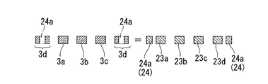
ダミーパターン24は、金型40の内部14に形成された凸部23a、23b、23c、23dの合計体積と、凹部の合計容積との差を相殺するものである。本実施形態において、ダミーパターン24を含めない凸部の合計体積とは、図2Aに示すように、下金型1の底部から突出している凸部23a、23b、23c、23dの合計体積である。また、本実施形態において、ダミーパターン24を含めない凹部の合計容積とは、下金型1の上面に沿う仮想面と下金型1との間の容積であって、凸部23a、23b、23c、23d間に配置された凹部3a、3b、3cの内側の容積と、凸部23a、23b、23c、23dと内部14の側面14bとの間に配置された凹部3dの内側の容積との合計容積である。したがって、本実施形態においては、図2Aに示すように、ダミーパターン24を含めない場合、凸部の合計体積が凹部の合計容積よりも少なくなっている。
The
本実施形態においては、ダミーパターン24として、凸部23a、23b、23c、23dと内部14の側面14bとの間に、凸部23a、23b、23c、23dと同じ高さの断面視四角形で平面視ストライプ状のダミー凸部24a、24aが、凹凸パターン3を挟むように並行に設けられている。したがって、ダミーパターン24を含めた場合、図2Bに示すように、凸部23a、23b、23c、23dと内部14の側面14bとの間に配置された凹部3dの容積がダミー凸部24a、24aの体積分減少し、凸部の合計体積がダミー凸部24a、24aの体積分増加し、凸部の合計体積と凹部の合計容積との差が相殺され、凸部の合計体積と凹部の合計容積とが略等しくなっている。
In the present embodiment, as the
なお、本実施形態においては、凸部の合計体積が凹部の合計容積よりも小さくなっているため、ダミーパターン24としてダミー凸部24a、24aを設けたが、凸部の合計体積が凹部の合計容積よりも多くなっている場合には、ダミーパターンとしてダミー凹部が設けられる。
In this embodiment, since the total volume of the convex portions is smaller than the total volume of the concave portions, the dummy
また、ダミーパターン24の形状は、凸部の合計体積と凹部の合計容積との差を相殺できる容積(体積)であればよく、特に限定されないが、図2Aに示すように、ダミーパターン24がダミー凸部24a、24aである場合、ダミー凸部24a、24aの高さが凸パターン3の凸部23a、23b、23c、23dと同じ高さであることが好ましく、ダミーパターンがダミー凹部である場合、凹凸パターンの凹部3a、3b、3cと同じ深さであることが好ましい。この場合、ダミー凸部(ダミー凹部)の高さ(深さ)が、凹凸パターン3の凸部(凹部)の高さ(深さ)と異なっている場合と比較して、プレス工程を行った際におけるシート状材料20の圧縮変形量のばらつきが低減されるので、成形品30の板厚偏差をより一層小さくできる。
The shape of the
また、ダミーパターン24の配置は、特に限定されないが、複数個所に設けられていることが好ましい。ダミーパターン24が複数個所に設けられている場合、ダミーパターンが1箇所に設けられている場合と比較して、プレス工程を行った際におけるシート状材料20の圧縮変形量のばらつきが低減されるので、成形品30の板厚偏差をより一層小さくできる。なお、本実施形態においては、ダミーパターン24として、凹凸パターン3を挟むように並行に2箇所設けたが、1箇所であってもよいし、3箇所以上であってもよい。
The arrangement of the
また、ダミーパターンの配置は、図2Aに示す例に限定されるものではなく、凹凸パターンを構成する凹部および凸部の配置に応じて決定されることが好ましい。凹凸パターンを構成する凹部および凸部の配置に偏りがある場合、プレス工程を行った際におけるシート状材料20の圧縮変形量のばらつきが大きくなりやすく、成形品30の板厚偏差も大きくなりやすい。したがって、プレス工程を行った際におけるシート状材料20の圧縮変形量のばらつきを効果的に低減させるためには、凹凸パターンを構成する凹部および凸部の配置の偏りが大きい領域の近傍に、ダミーパターンを配置することが好ましい。例えば、ダミーパターンとしてダミー凸部を設ける場合、シート状材料20の圧縮変形量の小さい領域の近傍に配置されることが好ましく、ダミーパターンとしてダミー凹部を設ける場合、シート状材料20の圧縮変形量の大きい領域の近傍に配置されることが好ましい。より具体的には、プレス工程を行った際におけるシート状材料20の圧縮変形量を効果的に均一化するために、ダミーパターンを、凹凸パターン3を取り囲むように複数配置することが好ましい。ダミーパターンを凹凸パターン3の外周部に設けると、成形品30として燃料電池用セパレータを製造した場合に、燃料電池用セパレータの導電性に支障を来たす恐れや、流路用パターンの流動性に支障を来たす恐れがなく、好ましい。しかし、凹凸パターンを構成する凹部および凸部の幅が不均一である場合には、プレス工程を行った際におけるシート状材料20の圧縮変形量のばらつきを効果的に低減させるために、凹凸パターンの中にダミーパターンを配置することが好ましい。
Further, the arrangement of the dummy patterns is not limited to the example shown in FIG. 2A, but is preferably determined according to the arrangement of the concave portions and the convex portions constituting the concave / convex pattern. When there is a bias in the arrangement of the concave and convex portions constituting the concavo-convex pattern, variation in the amount of compressive deformation of the sheet-
なお、金型設計時の制約条件等により凹凸パターン3を有する型にダミーパターンを配置することが困難な場合などには、凹凸パターン3と対向する別の型(図2Aに示す例においては上金型12)の内面にダミーパターンを配置してもよい。この場合のダミーパターンの平面配置は、凹凸パターン3を有する型にダミーパターンを設ける場合と同様に、凹凸パターン3を取り囲むように複数配置することが好ましい。また、凹凸パターン3と対向する別の型にダミーパターンを設ける場合においても、凹凸パターンを構成する凹部および凸部の幅が不均一である場合には、凹凸パターンの中にダミーパターンを配置することが好ましい。
If it is difficult to place a dummy pattern on a mold having the concave /
また、ダミーパターン24は、図2Aに示すように、凹凸パターン3の外側に設けられていてもよいし、成形品30に支障を来たすことがなければ、凹凸パターン3の内側に設けられていてもよい。
また、ダミーパターン24は、成形品30として燃料電池用セパレータを製造する場合、燃料電池用セパレータのガス供給穴となる領域に対応する位置に設けられていることが好ましい。この場合、成形品30にダミーパターン24が転写されてなるパターンを、燃料電池用セパレータにガス供給穴を形成する際のガイドなどとして用いることができる。この場合、ガス供給穴を容易に形成できるため、好ましい。なお、燃料電池用セパレータのガス供給穴は、通常、燃料電池用セパレータを貫通する穴を設けることにより形成される。したがって、ガス供給穴が形成されることにより、ダミーパターンが転写されてなるパターンは消失されるが、燃料電池用セパレータの成形後であるので消失しても問題ない。Further, as shown in FIG. 2A, the
Further, when a fuel cell separator is manufactured as the molded
また、成形品30として燃料電池用セパレータを製造する場合、成形品30の凹凸パターン部32である流路用パターンの外縁部や、燃料ガス等を通すためのマニホールド穴(ガス供給穴)の外縁部には、パッキンが配置される。このため、ダミーパターン24は、パッキンの配置される位置を避けて配置されることが好ましい。
なお、ダミー凹部またはダミー凸部からなるダミーパターンは、流路用パターンの外縁部や、燃料ガス等を通すためのマニホールド穴の外縁部に沿って配置した場合、流路用パターンを形成した後や、マニホールド穴を形成した後に、パッキンとして機能するものとすることができる。この場合、ダミーパターンは、パッキンとしても用いられるものであるので、パッキンの配置されるべき位置に設けられる。When a fuel cell separator is manufactured as the molded
In addition, the dummy pattern which consists of a dummy recessed part or a dummy convex part, after arrange | positioning along the outer edge part of the pattern for flow paths, or the outer edge part of the manifold hole for letting fuel gas etc. pass, forms a pattern for flow paths Or after forming a manifold hole, it can function as packing. In this case, since the dummy pattern is also used as a packing, it is provided at a position where the packing is to be disposed.
ここで、成形品30として燃料電池用セパレータを製造する場合に用いられるシート状材料20について、説明する。成形品30として燃料電池用セパレータを製造する場合に用いられるシート状材料20は、充填材である炭素質材料(A)と、樹脂組成物(B)を必須成分として含むものである。「炭素質材料(A)」
炭素質材料(A)としては、カーボンブラック、炭素繊維(ピッチ系、PAN系)、アモルファスカーボン、膨張黒鉛、キッシュ黒鉛、人造黒鉛、天然黒鉛、気相法炭素繊維、カーボンナノチューブ、フラーレンなどの炭素質材料の中から選ばれる1種または2種類以上の混合物などが挙げられる。これらの中でカーボンブラックは導電性および充填性が他の材料に比べて低いので、炭素繊維(ピッチ系、PAN系)、アモルファスカーボン、膨張黒鉛、キッシュ黒鉛、人造黒鉛、天然黒鉛、気相法炭素繊維、カーボンナノチューブ、フラーレンの中から選ばれる一種又は二種以上の混合物が好ましい。
また、炭素質材料(A)は、ホウ素を含有するものであることが好ましく、中でも、ホウ素を含有する人造黒鉛が特に好適に使用可能である。Here, the sheet-
Carbonaceous materials (A) include carbon black, carbon fiber (pitch-based, PAN-based), amorphous carbon, expanded graphite, quiche graphite, artificial graphite, natural graphite, vapor grown carbon fiber, carbon nanotube, fullerene, etc. Examples thereof include one or a mixture of two or more selected from the quality materials. Among these, since carbon black has lower conductivity and filling properties than other materials, carbon fiber (pitch-based, PAN-based), amorphous carbon, expanded graphite, quiche graphite, artificial graphite, natural graphite, gas phase method One or a mixture of two or more selected from carbon fibers, carbon nanotubes, and fullerenes is preferred.
In addition, the carbonaceous material (A) preferably contains boron, and among them, artificial graphite containing boron can be used particularly suitably.
(カーボンブラック)
炭素質材料(A)の一例であるカーボンブラックとしては、天然ガス等の不完全燃焼、アセチレンの熱分解により得られるケッチェンブラック、アセチレンブラック、炭化水素油や天然ガスの不完全燃焼により得られるファーネスカーボン、天然ガスの熱分解により得られるサーマルカーボン等が挙げられる。(Carbon black)
Carbon black, which is an example of the carbonaceous material (A), is obtained by incomplete combustion of natural gas or the like, ketjen black obtained by thermal decomposition of acetylene, acetylene black, hydrocarbon oil or natural gas. Examples include furnace carbon and thermal carbon obtained by thermal decomposition of natural gas.
(炭素繊維)
炭素質材料(A)の一例である炭素繊維(ピッチ系、PAN系)としては、重質油、副生油、コールタール等から作られるピッチ系や、ポリアクリロニトリルから作られるPAN系などが挙げられる。
炭素繊維の平均繊維長は、SEM(日本電子社製、JSM−5510)を用いて観察した100本の繊維長を画像解析することによって数平均繊維長を測定して得られる。なお、ここで言う炭素繊維とは、(長軸の長さ/短軸の長さ)の比が10以上のものをいう。(Carbon fiber)
Carbon fibers (pitch-based, PAN-based) as an example of the carbonaceous material (A) include pitch-based made from heavy oil, by-product oil, coal tar, PAN-based made from polyacrylonitrile, etc. It is done.
The average fiber length of the carbon fiber is obtained by measuring the number average fiber length by image analysis of 100 fiber lengths observed using SEM (manufactured by JEOL Ltd., JSM-5510). The carbon fiber referred to here is one having a ratio of (major axis length / minor axis length) of 10 or more.
(アモルファスカーボン)
炭素質材料(A)の一例であるアモルファスカーボンとしては、フェノール樹脂を硬化させて焼成処理し粉砕して粉末とする方法、または、フェノール樹脂を球状、不定形状の粉末の状態で硬化させて焼成処理する方法等によって得られたものなどが挙げられる。導電性の高いアモルファスカーボンを得るためには2000℃以上の加熱処理を行うことが好ましい。(Amorphous carbon)
As an example of the carbonaceous material (A), the amorphous carbon is a method in which a phenol resin is cured and baked and pulverized to obtain a powder, or the phenol resin is cured in a spherical, indefinite shape powder and baked. What was obtained by the method of processing etc. is mentioned. In order to obtain highly conductive amorphous carbon, it is preferable to perform a heat treatment at 2000 ° C. or higher.
(膨張黒鉛)
炭素質材料(A)の一例である膨張黒鉛としては、例えば、天然黒鉛、熱分解黒鉛等の高度に結晶構造が発達した黒鉛を、濃硫酸と硝酸との混液、濃硫酸と過酸化水素水との混液の強酸化性の溶液に浸漬処理して黒鉛層間化合物を生成させ、水洗してから急速加熱し、黒鉛結晶のC軸方向を膨張処理することによって得られた粉末や、それを一度シート状に圧延したものを粉砕して得られた粉末などが挙げられる。(Expanded graphite)
Examples of the expanded graphite which is an example of the carbonaceous material (A) include graphite having a highly crystal structure such as natural graphite and pyrolytic graphite, a mixed solution of concentrated sulfuric acid and nitric acid, concentrated sulfuric acid and hydrogen peroxide solution. A graphite intercalation compound is formed by immersion in a strong oxidizing solution mixed with the powder, washed with water and then rapidly heated to expand the powder in the C-axis direction of the graphite crystal, Examples thereof include a powder obtained by pulverizing a sheet rolled.
(キッシュ黒鉛)
炭素質材料(A)の一例であるキッシュ黒鉛としては、溶けた銑鉄が、溶銑予備処理等で温度低下するのに伴い析出した、平面的に結晶化した炭素などが挙げられる。このキッシュ黒鉛は、スラグや酸化鉄に混じったものとして発生するため、選鉱によって純度の高いキッシュ黒鉛を回収して更に粉砕して用途に合うサイズに仕上げた粉末が好ましく用いられる。(Quiche graphite)
Examples of the quiche graphite that is an example of the carbonaceous material (A) include planarly crystallized carbon that is precipitated as molten pig iron is lowered in temperature by hot metal pretreatment or the like. Since this quiche graphite is generated as a mixture with slag and iron oxide, a powder obtained by collecting high-purity quiche graphite by beneficiation and further pulverizing it to a size suitable for the use is preferably used.
(人造黒鉛)
炭素質材料(A)の一例である人造黒鉛としては、例えば以下に示す方法により得られた黒鉛化粉末などが用いられる、通常、人造黒鉛を得るためには、コークスを製造する。コークスの原料としては、石油系ピッチや石炭系のピッチ等が用いられる。これらの原料を炭化してコークスとする。コークスから黒鉛化粉末を得るには、一般的に、コークスを粉砕した後に黒鉛化処理する方法、コークス自体を黒鉛化した後に粉砕する方法、あるいはコークスにバインダーを加え成形、焼成した焼成品(コークスおよびこの焼成品を合わせてコークス等という)を黒鉛化処理した後に粉砕して粉末とする方法等がある。原料のコークス等は、できるだけ結晶が発達していない方が良いので、2000℃以下、好ましくは1200℃以下で加熱処理したものが適する。また、黒鉛化処理する方法は、粉末を黒鉛ルツボに入れて直接通電するアチソン炉を用いる方法や、黒鉛発熱体により粉末を加熱する方法等を使用することができる。(Artificial graphite)
As artificial graphite which is an example of the carbonaceous material (A), for example, graphitized powder obtained by the method shown below is used. Usually, in order to obtain artificial graphite, coke is produced. As a raw material for coke, petroleum pitch, coal pitch, or the like is used. These raw materials are carbonized into coke. In order to obtain graphitized powder from coke, generally, a method of pulverizing coke and then graphitizing, a method of pulverizing coke itself and then pulverizing, or a calcined product formed by adding binder to coke and calcined (coke) In addition, there is a method in which the calcined product is co-graphitized and then pulverized into powder. Since it is better for the raw material coke or the like to have as little crystals as possible, a heat-treated material at 2000 ° C. or lower, preferably 1200 ° C. or lower is suitable. As a method for graphitizing, a method using an Atchison furnace in which powder is placed in a graphite crucible and directly energized, a method of heating powder with a graphite heating element, or the like can be used.
(気相法炭素繊維、カーボンナノチューブ)
炭素質材料(A)は、気相法炭素繊維および/またはカーボンナノチューブを0.1〜50質量%含むことが好ましい。より好ましくは、0.1〜45質量%であり、更に好ましくは、0.2〜40質量%である。(Gas-phase carbon fiber, carbon nanotube)
The carbonaceous material (A) preferably contains 0.1 to 50% by mass of vapor grown carbon fiber and / or carbon nanotube. More preferably, it is 0.1-45 mass%, More preferably, it is 0.2-40 mass%.
(気相法炭素繊維)
気相法炭素繊維としては、例えば、ベンゼン、トルエン、天然ガス、炭化水素系ガス等の有機化合物を原料とし、フェロセン等の遷移金属触媒の存在下で、水素ガスとともに800〜1300℃で熱分解反応させることによって得られる、繊維長約0.5〜10μm、繊維径200nm以下の炭素繊維などが挙げられる。繊維径のより好ましいサイズは160nm以下であり、更に好ましくは120nm以下である。繊維径が200nmよりも大きいと、高い導電性を得る効果が小さくなるので好ましくない。更に、上記の方法によって得られた炭素繊維は、約2300〜3200℃で黒鉛化処理されることが好ましい。なお、ここでの黒鉛化処理は、ホウ素、炭化ホウ素、ベリリウム、アルミニウム、ケイ素等の黒鉛化触媒とともに、不活性ガス雰囲気中で行われることがより好ましい。(Vapor grown carbon fiber)
As vapor grown carbon fiber, for example, organic compounds such as benzene, toluene, natural gas, hydrocarbon gas, etc. are used as raw materials and thermally decomposed at 800-1300 ° C. together with hydrogen gas in the presence of a transition metal catalyst such as ferrocene. Examples thereof include carbon fibers obtained by reacting and having a fiber length of about 0.5 to 10 μm and a fiber diameter of 200 nm or less. A more preferable size of the fiber diameter is 160 nm or less, and further preferably 120 nm or less. If the fiber diameter is larger than 200 nm, the effect of obtaining high conductivity is reduced, which is not preferable. Further, the carbon fiber obtained by the above method is preferably graphitized at about 2300 to 3200 ° C. In addition, it is more preferable that the graphitization process here is performed in inert gas atmosphere with graphitization catalysts, such as boron, boron carbide, beryllium, aluminum, and silicon.
(カーボンナノチューブ)
カーボンナノチューブは、近年その機械的強度のみでなく、電界放出機能や、水素吸蔵機能が産業上注目され、更に磁気機能にも目が向けられ始めている。この種のカーボンナノチューブは、グラファイトウィスカー、フィラメンタスカーボン、グラファイトファイバー、極細炭素チューブ、カーボンチューブ、カーボンフィブリル、カーボンマイクロチューブ、カーボンナノファイバー等とも呼ばれており、繊維径が約0.5〜100nmのものである。カーボンナノチューブには、チューブを形成するグラファイト膜が一層である単層カーボンナノチューブと、多層である多層カーボンナノチューブがある。本発明では、単層および多層カーボンナノチューブのいずれも使用可能であるが、単層カーボンナノチューブを用いた方が、より高い導電性や機械的強度の組成物が得られる傾向があるため好ましい。(carbon nanotube)
In recent years, not only the mechanical strength of carbon nanotubes but also the field emission function and the hydrogen storage function have attracted industrial attention, and the magnetic function has begun to pay attention. This type of carbon nanotube is also called graphite whisker, filamentous carbon, graphite fiber, ultrafine carbon tube, carbon tube, carbon fibril, carbon microtube, carbon nanofiber, etc., and the fiber diameter is about 0.5-100 nm belongs to. Carbon nanotubes include single-walled carbon nanotubes having a single graphite film forming a tube and multi-walled carbon nanotubes having multiple layers. In the present invention, both single-walled and multi-walled carbon nanotubes can be used. However, it is preferable to use single-walled carbon nanotubes because a composition having higher conductivity and mechanical strength tends to be obtained.
カーボンナノチューブは、例えば、斉藤・板東「カーボンナノチューブの基礎」(23〜57頁、コロナ社出版、1998年発行)に記載のアーク放電法、レーザー蒸発法および熱分解法等により作製し、更に純度を高めるために水熱法、遠心分離法、限外ろ過法、および酸化法等により精製することによって得られる。より好ましくは、不純物を取り除くために約2300〜3200℃の不活性ガス雰囲気中で高温処理する。更に好ましくは、ホウ素、炭化ホウ素、ベリリウム、アルミニウム、ケイ素等の黒鉛化触媒とともに、不活性ガス雰囲気中、約2300〜3200℃で高温処理する。 Carbon nanotubes are produced, for example, by the arc discharge method, laser evaporation method, thermal decomposition method, etc. described in Saito and Itoh “Basics of Carbon Nanotubes” (pages 23-57, published by Corona, 1998), and further purity. In order to increase the pH, it is obtained by purification by a hydrothermal method, a centrifugal separation method, an ultrafiltration method, an oxidation method or the like. More preferably, high temperature treatment is performed in an inert gas atmosphere at about 2300 to 3200 ° C. to remove impurities. More preferably, a high temperature treatment is performed at about 2300 to 3200 ° C. in an inert gas atmosphere together with a graphitization catalyst such as boron, boron carbide, beryllium, aluminum and silicon.
(ホウ素を含有する炭素質材料)
ホウ素は、炭素質材料(A)中に0.05〜5質量%含まれることが好ましく、0.06〜4質量%含まれることがより好ましく、0.06〜3質量%含まれることが更に好ましい。ホウ素の含有量が0.05質量%未満であると、目的とする高導電性の炭素質材料が得られ難い傾向がある。また、ホウ素の含有量が5質量%を超えて含まれていても、炭素質材料の導電性の向上に寄与し難くなる傾向があるし、不純物量が多くなり、他の物性の低下をもたらす傾向が生じ易くなる。(Carbonaceous material containing boron)
Boron is preferably contained in the carbonaceous material (A) in an amount of 0.05 to 5% by mass, more preferably 0.06 to 4% by mass, and further preferably 0.06 to 3% by mass. preferable. If the boron content is less than 0.05% by mass, the intended highly conductive carbonaceous material tends to be difficult to obtain. Further, even if the boron content exceeds 5 mass%, it tends to be difficult to contribute to the improvement of the conductivity of the carbonaceous material, the amount of impurities increases, and other physical properties are deteriorated. A tendency tends to occur.
炭素質材料に含まれるホウ素の含有量の測定方法としては特に制限はない。例えば、誘導型プラズマ発光分光分析法(以下、「ICP」と略記する)や、誘導型プラズマ発光分光質量分析法(以下、「ICP−MS」と略記する)により測定した値を用いることができる。具体的には、例えば、試料であるホウ素を含有する炭素質材料に、硫酸および硝酸を加え、マイクロ波で230℃に加熱して分解(ダイジェスター法)し、更に過塩素酸(HClO4)を加えて分解したものを水で希釈し、これをICP発光分析装置にかけて、ホウ素量を測定する方法などが挙げられる。There is no particular limitation on the method for measuring the content of boron contained in the carbonaceous material. For example, a value measured by inductive plasma emission spectrometry (hereinafter abbreviated as “ICP”) or induction plasma emission spectroscopic mass spectrometry (hereinafter abbreviated as “ICP-MS”) can be used. . More specifically, for example, sulfuric acid and nitric acid are added to a carbonaceous material containing boron as a sample, heated to 230 ° C. by microwaves (digester method), and further perchloric acid (HClO 4 ). A method of diluting a product decomposed by adding water and applying it to an ICP emission spectrometer and measuring the amount of boron is exemplified.
炭素質材料(A)中にホウ素を含有させる方法としては、例えば、カーボンブラック、炭素繊維、アモルファスカーボン、膨張黒鉛、キッシュ黒鉛、人造黒鉛、天然黒鉛、気相法炭素繊維、カーボンナノチューブ、フラーレンなどの炭素質材料の中から選ばれる1種または2種類以上の混合物と、ホウ素源であるB単体、B4C、BN、B2O3、H3BO3等とを混合して、約2300〜3200℃で黒鉛化処理する方法などが挙げられる。炭素質材料とホウ素源との混合が不均一である場合には、ホウ素を含有する炭素質材料が不均一になるのみならず、黒鉛化処理時に焼結する可能性が高くなる。炭素質材料とホウ素源とを均一に混合させるためには、上記のホウ素源を50μm以下、好ましくは20μm以下程度の粒径を有する粉末にしてから、上記の炭素質材料の粉末に混合することが好ましい。Examples of the method for incorporating boron into the carbonaceous material (A) include carbon black, carbon fiber, amorphous carbon, expanded graphite, quiche graphite, artificial graphite, natural graphite, vapor grown carbon fiber, carbon nanotube, fullerene and the like. 1 type or a mixture of two or more types selected from the above carbonaceous materials and boron simple substance B, B 4 C, BN, B 2 O 3 , H 3 BO 3, etc. Examples thereof include a method of graphitizing at ˜3200 ° C. When the mixing of the carbonaceous material and the boron source is not uniform, the carbonaceous material containing boron not only becomes nonuniform, but also increases the possibility of sintering during graphitization. In order to uniformly mix the carbonaceous material and the boron source, the boron source is made into a powder having a particle size of about 50 μm or less, preferably about 20 μm or less, and then mixed with the powder of the carbonaceous material. Is preferred.
また、ホウ素を含有する炭素質材料中に含まれるホウ素の含有の形態は、ホウ素および/またはホウ素化合物が炭素質材料中に混合されていればよく、特に制限されないが、炭素質材料が黒鉛結晶を有する場合、ホウ素および/またはホウ素化合物が黒鉛結晶の層間に存在するものや、黒鉛結晶を形成する炭素原子の一部がホウ素原子に置換されたものであることが、より好ましい。また、炭素原子の一部がホウ素原子に置換されている場合、ホウ素原子と炭素原子との結合は、共有結合、イオン結合等どのような結合様式であっても構わない。 Further, the form of boron contained in the carbonaceous material containing boron is not particularly limited as long as boron and / or boron compounds are mixed in the carbonaceous material. More preferably, boron and / or boron compounds are present between the layers of the graphite crystals, or carbon atoms that form the graphite crystals are partially substituted with boron atoms. In addition, when a part of the carbon atom is substituted with a boron atom, the bond between the boron atom and the carbon atom may be any bond mode such as a covalent bond or an ionic bond.
(コークス等の粉砕)
炭素質材料の製造に用いられるコークスや、炭素質材料として用いられる人造黒鉛や天然黒鉛等の粉砕には、高速回転粉砕機(ハンマーミル、ピンミル、ケージミル)や各種ボールミル(転動ミル、振動ミル、遊星ミル)、撹拌ミル(ビーズミル、アトライター、流通管型ミル、アニュラーミル)等の粉砕機が使用できる。また、微粉砕機であるスクリーンミル、ターボミル、スーパーミクロンミル、ジェットミルなども、条件を選定することによって使用可能である。コークスおよび天然黒鉛等は、これらの粉砕機を用いて粉砕し、その際の粉砕条件の選定、および必要により粉末を分級し、平均粒径や粒度分布をコントロールして用いることが好ましい。(Crushing of coke, etc.)
Coke used in the production of carbonaceous materials, artificial graphite and natural graphite used as carbonaceous materials, etc. are pulverized by high-speed rotary pulverizer (hammer mill, pin mill, cage mill) and various ball mills (rolling mill, vibration mill). , Planetary mills), stirring mills (bead mills, attritors, distribution pipe mills, annular mills) and the like. Further, a screen mill, a turbo mill, a supermicron mill, a jet mill, etc., which are fine pulverizers, can be used by selecting the conditions. Coke, natural graphite, and the like are preferably pulverized using these pulverizers, and the pulverization conditions are selected at that time, and the powder is classified as necessary, and the average particle size and particle size distribution are controlled and used.
(コークス等の分級)
コークス粉末、人造黒鉛粉末および天然黒鉛粉末等を分級する方法としては、分離が可能であれば何れでも良いが、例えば、篩分法や強制渦流型遠心分級機(ミクロンセパレーター、ターボプレックス、ターボクラシファイアー、スーパーセパレーター)、慣性分級機(改良型バーチュウアルインパクター、エルボジェット)等の気流分級機が使用できる。また、湿式の沈降分離法や遠心分級法等も使用できる。(Classification of coke etc.)
As a method for classifying coke powder, artificial graphite powder, natural graphite powder, etc., any method can be used as long as separation is possible. For example, a sieving method or a forced vortex type centrifugal classifier (micron separator, turboplex, turboclassic) Airflow classifiers such as fire and super separators and inertia classifiers (improved virtual impactor and elbow jet) can be used. Further, a wet sedimentation method or a centrifugal classification method can be used.
「樹脂組成物(B)」
樹脂組成物(B)としては、例えば、熱硬化性樹脂や熱可塑性樹脂が挙げられる。
燃料電池用セパレータの耐久性の観点から、燃料電池用セパレータの融点、またはガラス転移温度が120℃以上となる樹脂を用いることが好ましい。
また、燃料電池用セパレータの耐熱水性を向上させるためには、樹脂組成物(B)として、1,2−ポリブタジエン、3,4−ポリイソプレン、ノボラック型エポキシ樹脂、ノボラック型フェノール樹脂、ポリエチレン、ポリプロピレン、ポリメチルペンテン、ポリスチレン、ポリフェニレンスルフィド、ポリシクロオレフィン、ポリブテン−1、ポリフェニレンエーテル、ポリエーテルエーテルケトン、フッ素樹脂、または液晶ポリマーより選ばれる1成分以上をシート状材料である炭素質材料(A)および樹脂組成物(B)を含む導電性樹脂組成物中に2質量%〜20質量%含有するものであることが望ましく、特に1,2−ポリブタジエン、3,4−ポリイソプレン、ポリエチレン、ポリプロピレン、ポリブテン−1より選ばれる1成分以上が上記含有量で含まれていることが好ましい。"Resin composition (B)"
Examples of the resin composition (B) include a thermosetting resin and a thermoplastic resin.
From the viewpoint of durability of the fuel cell separator, it is preferable to use a resin whose melting point or glass transition temperature of the fuel cell separator is 120 ° C. or higher.
Moreover, in order to improve the hot water resistance of the fuel cell separator, the resin composition (B) includes 1,2-polybutadiene, 3,4-polyisoprene, novolac epoxy resin, novolac phenol resin, polyethylene, polypropylene. Carbonaceous material (A) which is a sheet-like material containing at least one component selected from polymethylpentene, polystyrene, polyphenylene sulfide, polycycloolefin, polybutene-1, polyphenylene ether, polyether ether ketone, fluororesin, or liquid crystal polymer And 2 to 20% by mass in the conductive resin composition containing the resin composition (B), particularly 1,2-polybutadiene, 3,4-polyisoprene, polyethylene, polypropylene, 1 selected from polybutene-1 Or it is preferably contained in the content.
(他の添加剤)
成形品30が燃料電池用セパレータである場合に用いられるシート状材料20には、充填材である炭素質材料(A)と、樹脂組成物(B)の他に、必要に応じてモノマー、反応開始剤、エラストマー、ゴム、及び樹脂改質剤などを含有させることができる。さらに、成形品30が燃料電池用セパレータである場合に用いられるシート状材料20には、硬度、強度、導電性、成形性、耐久性、耐候性、耐水性等を改良する目的で、ガラスファイバー、ウィスカー、金属酸化物、有機繊維、紫外線安定剤、酸化防止剤、離型剤、滑剤、撥水剤、増粘剤、低収縮剤、親水性付与剤等の添加剤を、必要に応じて含有させることができる。(Other additives)
The sheet-
本実施形態のシートプレス成形方法は、少なくとも一方に凹部3a、3b、3cと凸部23a、23b、23c、23dとからなる所定の凹凸パターン3を有する一対の金型40を用いて、60〜95体積%の充填材と樹脂組成物とを含むシート状材料20を加圧することにより、凹凸パターン3の転写された凹凸パターン部32を有する成形品30を形成する工程を備え、一対の金型40として、内部14に形成された凸部23a、23b、23c、23dの合計体積と、凸部23a、23b、23c、23dと内部14の側面14bとの間および凸部23a、23b、23c、23d間に配置された凹部3a、3b、3cの合計容積との差を相殺するダミー凸部24aからなるダミーパターン24が、内部14に設けられたものを用いる方法である。このため、成形体30の凸部の体積が成形体30の凹部の容積と同じとなり、プレス工程を行った際に、金型40の凸部に加圧されて押し出される軟化したシート状材料20が、金型40の凹部と対向される部分にスムーズに埋め込まれるようになる。よって、プレス工程を行った際のシート状材料20の圧縮変形量の差を小さくすることができる。
その結果、本実施形態のシートプレス成形方法によれば、充填材と樹脂組成物とを含むシート状材料20が多量の充填材を含むものであったり、凹凸パターン3が微細化されたものであったりしても、これをプレス成形することによって成形品30を製造した場合に、板厚偏差の小さい成形品30が得られる。The sheet press molding method of the present embodiment uses a pair of
As a result, according to the sheet press molding method of the present embodiment, the sheet-
本実施形態の燃料電池用セパレータの製造方法は、充填材が炭素質材料であるシート状材料20を用いる本実施形態のシートプレス成形方法を用いて、成形品30として燃料電池用セパレータを製造する方法であるので、炭素質材料と樹脂組成物とを含むシート状材料20として、多量の炭素質材料を含むものを用い、これをプレス成形することによって、板厚偏差が小さく、高い強度および高い導電性を有する燃料電池用セパレータが得られる。
また、本実施形態の燃料電池用セパレータの製造方法においては、凹凸パターン3として微細化されたものを用いることで、板厚偏差が小さく、微細な流路用パターンを有する燃料電池用セパレータが容易に得られる。
また、本実施形態の燃料電池用セパレータの製造方法においては、シート状材料を一対の型を用いて加圧することにより、流路用パターンを有する燃料電池用セパレータを形成するので、厚みの薄い燃料電池用セパレータを効率よく製造でき、量産に好適である。The manufacturing method of the separator for fuel cells of this embodiment manufactures the separator for fuel cells as the molded
Further, in the method for manufacturing a fuel cell separator according to the present embodiment, by using a fine pattern as the
Further, in the method for manufacturing a fuel cell separator according to the present embodiment, a fuel cell separator having a flow path pattern is formed by pressurizing a sheet material using a pair of molds. Battery separators can be produced efficiently and are suitable for mass production.
以下、実施例を示して本発明を具体的に説明する。
(実施例)
充填材が炭素質材料であるシート状材料を用い、本発明のシートプレス成形方法を用いて、成形品として実施例の燃料電池用セパレータを製造した。
すなわち、凹凸パターンを有する以下に示す一対の型を用いて、以下に示すシート状材料を加圧することにより、凹凸パターンの転写された流路用パターン31と、ダミーパターンの転写された複数の凹部24b、24c、24d、24eとを片面に有する図3に示す燃料電池用セパレータ35を得た。図3A〜図3Dは、実施例および比較例の燃料電池用セパレータを示した図面である。図3Aは実施例の燃料電池用セパレータの平面図であり、図3Bは図3AのA−A’断面の断面図である。また、図3Cは比較例の燃料電池用セパレータの平面図であり、図3Dは図3CのB−B’断面の断面図である。Hereinafter, the present invention will be specifically described with reference to examples.
(Example)
Using the sheet-like material whose filler is a carbonaceous material, the separator for a fuel cell of the example was manufactured as a molded article using the sheet press molding method of the present invention.
That is, by using the following pair of molds having a concavo-convex pattern and pressing the sheet-like material shown below, the
「金型」
ここで、図3Aおよび図3Bを用いて、実施例の燃料電池用セパレータをプレス成形する際に用いた下金型の内部形状について説明する。
実施例においては、金型として、下金型の内部に、凹部と凸部とからなる下記の凹凸パターンと、下記のダミー凸部からなるダミーパターンとが設けられた上下一対の金型を用いた。なお、実施例において用いた金型は、ダミーパターンを含めない場合、内部に形成された凸部の合計体積が凹部の合計容積よりも少なくなっているが、ダミーパターンを含めた場合には、内部に形成された凸部の合計体積と凹部の合計容積との差が相殺されて同じとなっているものである。"Mold"
Here, the internal shape of the lower mold used when the fuel cell separator of the example is press-molded will be described with reference to FIGS. 3A and 3B.
In the embodiment, a pair of upper and lower molds provided with the following concave / convex pattern consisting of concave and convex parts and the following dummy pattern consisting of dummy convex parts inside the lower mold are used as the molds. It was. In addition, when the mold used in the embodiment does not include the dummy pattern, the total volume of the convex portions formed inside is smaller than the total volume of the concave portions, but when the dummy pattern is included, The difference between the total volume of the convex portions formed inside and the total volume of the concave portions is offset and is the same.
凹凸パターン(図3Aおよび図3Bにおける流路用パターン31に対応する):深さ0.5mm、幅下辺(底部幅)2.1mm、幅上辺(上部幅)1.9mm、平均幅2mmの断面視台形形の凸部(燃料電池用セパレータにおける溝)を、長さ160mm、幅62mmの領域に4mmピッチ(幅上辺間の間隔2mm)で、長さ方向が凸部(溝)の長さ方向となるように、ストライプ状に配置した。
Uneven pattern (corresponding to the
ダミーパターン:高さ(深さ)0.5mmのダミー凸部(図3Aおよび図3Bにおける凹部24b、24c、24d、24eに対応する)を、流路用パターン31を2重に取り囲むように、流路用パターン31の外周部に設けた。なお、各ダミー凸部の面積は、下金型の内部に形成された凸部の合計体積と凹部の合計容積とが同じとなるように調整した。
内側のダミー凸部(図3Aおよび図3Bにおける凹部24bに対応する)は、燃料電池用セパレータのガス供給穴となる領域36に対応する位置に、パッキンの配置される位置を避けることのできる幅で分割して6箇所配置し、燃料電池用セパレータ35の凹部24bを、燃料電池用セパレータにガス供給穴を形成する際のガイドとして用いることができるようにした。また、外側のダミー凸部(図3Aおよび図3Bにおける凹部24cに対応する)は、パッキンの配置される位置を避けて内側のダミー凸部の外側に、4箇所配置した。また、ダミー凸部(図3Aにおける凹部24dに対応する)は、流路用パターン31の外周部であって、内側のダミー凸部の配置されていない領域である燃料電池用セパレータ35の中央部に2箇所設けた。さらに、燃料電池用セパレータ35の4つの角部に、それぞれダミー凸部(図3Aにおける凹部24eに対応する)を設けた。Dummy pattern: A dummy convex part (corresponding to the
The inner dummy convex portion (corresponding to the
「シート状材料」
(炭素質材料の製造)
まず、非針状コークス(MCコークス:エム・シー・カーボン株式会社製)をパルベライザー(ホソカワミクロン株式会社製)で3mm以下の大きさに粗粉砕した。次いで、この粗粉砕品をジェットミル(IDS2UR:日本ニューマチック株式会社製)で微粉砕し、分級により粒径を調整した。この分級においては、ターボクラシファイアー(TC15N:日清エンジニアリング株式会社製)を用いる気流分級を行うことにより、5μm以下の粒子を除去した。次に、粒径を調整した微粉砕品14.85kgに、炭化ホウ素(B4C)0.15kgを加えて、ヘンシェルミキサーにて回転数800rpmで5分間混合した。続いて、得られた混合物1kgを容量1.5リットルの蓋付き黒鉛ルツボに封入して黒鉛ヒータを用いた黒鉛化炉に入れ、黒鉛化炉内を一旦真空にしてからアルゴンガスに置換し、内圧1.2atm、アルゴンガス雰囲気の気流下で2800℃の温度で黒鉛化し、アルゴンガス雰囲気で放冷した。このようにして、0.49kgの人造黒鉛微粉が得られた。なお、得られた人造黒鉛微粉の平均粒径は20μmであった。"Sheet material"
(Manufacture of carbonaceous materials)
First, non-acicular coke (MC coke: manufactured by MC Carbon Co., Ltd.) was coarsely pulverized to a size of 3 mm or less with a pulverizer (manufactured by Hosokawa Micron Corporation). Subsequently, this coarsely pulverized product was finely pulverized by a jet mill (IDS2UR: manufactured by Nippon Pneumatic Co., Ltd.), and the particle size was adjusted by classification. In this classification, particles of 5 μm or less were removed by airflow classification using a turbo classifier (TC15N: manufactured by Nissin Engineering Co., Ltd.). Next, 0.15 kg of boron carbide (B 4 C) was added to 14.85 kg of the finely pulverized product whose particle size was adjusted, and mixed with a Henschel mixer at a rotation speed of 800 rpm for 5 minutes. Subsequently, 1 kg of the obtained mixture was enclosed in a graphite crucible with a lid having a capacity of 1.5 liters and placed in a graphitization furnace using a graphite heater, and the inside of the graphitization furnace was once evacuated and replaced with argon gas. Graphitization was performed at a temperature of 2800 ° C. under an internal gas pressure of 1.2 atm and an argon gas atmosphere, and the mixture was allowed to cool in an argon gas atmosphere. In this way, 0.49 kg of artificial graphite fine powder was obtained. In addition, the average particle diameter of the obtained artificial graphite fine powder was 20 μm.
また、平均粒径18μmの中国製の天然黒鉛(商品名BTRSG18:BTR Energy Materials社)を用いて、上記の粒径を調整した微粉砕品を用いた場合と同様にして炭化ホウ素と混合し、ホウ素含有天然黒鉛を得た。なお、得られたホウ素含有天然黒鉛の平均粒径は25μmであった。
このようにして得られた人造黒鉛微粉とホウ素含有天然黒鉛とを等量混合して炭素質材料とした。Further, using natural graphite made in China (trade name BTRSG18: BTR Energy Materials) with an average particle size of 18 μm, mixed with boron carbide in the same manner as in the case of using the finely pulverized product with the above particle size adjusted, Boron-containing natural graphite was obtained. The average particle size of the obtained boron-containing natural graphite was 25 μm.
The carbonaceous material was obtained by mixing equal amounts of the artificial graphite fine powder thus obtained and boron-containing natural graphite.
なお、人造黒鉛微粉およびホウ素含有天然黒鉛の平均粒径は、以下に示す方法により測定した。
まず、サンプル50mgを秤量して50mlの蒸留水に添加した。更に2%Triton(界面活性剤;和光純薬工業製社製)水溶液0.2mlを加えて3分間超音波分散させた後、レーザー回折散乱法(日機装(株)製のマイクロトラックHRA装置)で数平均粒子径を測定した。The average particle size of the artificial graphite fine powder and the boron-containing natural graphite was measured by the following method.
First, 50 mg of a sample was weighed and added to 50 ml of distilled water. Furthermore, after adding 0.2 ml of 2% Triton (surfactant; manufactured by Wako Pure Chemical Industries, Ltd.) aqueous solution and ultrasonically dispersing for 3 minutes, laser diffraction scattering method (Microtrac HRA apparatus manufactured by Nikkiso Co., Ltd.) was used. The number average particle size was measured.
(シート状材料の製造)
このようにして得られた炭素質材料と、表1に示す樹脂組成物と、表1に示す反応開始剤とを、ラボプラストミル(東洋精機製)を用いて温度100℃、回転数40rpmで5分間混練し、シート状材料となる成分を含む混練物を得た。この混練物を、ウィレー粉砕機(吉田製作所)を用いて粉砕し、篩下2mm以下の微粉とした。この微粉をオーブンで90℃まで加熱してロール表面温度30℃の10インチの圧延ロール(ダイハン製)に供給してシート化することにより、長さ200mm、幅100mm、厚み0.9mmのシート状材料を得た。
得られたシート状材料の炭素質材料の含有量は85質量%であり、炭素質材料中におけるホウ素の含有量は2質量%であり、密度は1.5g/cm3であった。
なお、ホウ素の含有量については、[0058]に記載の方法で測定した。また、ホウ素の密度については、JIS K7112のA法に規定された水中置換法(アルキメデス法)に基づいて測定された比重を密度として採用した。(Manufacture of sheet materials)
The carbonaceous material thus obtained, the resin composition shown in Table 1, and the reaction initiator shown in Table 1 were used at a temperature of 100 ° C. and a rotation speed of 40 rpm using a lab plast mill (manufactured by Toyo Seiki). The mixture was kneaded for 5 minutes to obtain a kneaded product containing components to be a sheet-like material. This kneaded product was pulverized using a Willet pulverizer (Yoshida Seisakusho) to obtain a fine powder of 2 mm or less under the sieve. This fine powder is heated to 90 ° C. in an oven and supplied to a 10-inch rolling roll (manufactured by Daihan) having a roll surface temperature of 30 ° C. to form a sheet, thereby forming a sheet having a length of 200 mm, a width of 100 mm, and a thickness of 0.9 mm. Obtained material.
The content of the carbonaceous material in the obtained sheet-like material was 85% by mass, the content of boron in the carbonaceous material was 2% by mass, and the density was 1.5 g / cm 3 .
The boron content was measured by the method described in [0058]. Moreover, about the density of boron, the specific gravity measured based on the underwater substitution method (Archimedes method) prescribed | regulated to A method of JISK7112 was employ | adopted as a density.

「プレス条件」
荷重250t、温度180℃、硬化時間2.5分とした。"Press conditions"
The load was 250 t, the temperature was 180 ° C., and the curing time was 2.5 minutes.
このようにして得られた実施例の燃料電池用セパレータ35の複数位置の厚みをマイクロメータにて実測し、板厚偏差を評価した。なお、燃料電池用セパレータ35の厚みの測定位置は、図4に示すように、外縁に沿って5mmの幅で設けられた余白領域の内側を、図4に示す寸法(図4に示す寸法の単位は(mm))で長さ方向および幅方向に各々略4等分し、長さ方向の分割した線および余白領域の内側境界線(図4において符号1〜5で示される点線)と、幅方向の分割した線および余白領域の内側境界線(図4において符号S1〜S5で示される点線)との交点位置とした。また、図4においては、図面を見やすくするために、凹部24b、24c、24d、24eの記載を省略して示している。その結果を図5Aおよび表2に示す。図5Aは、実施例の燃料電池用セパレータの板厚偏差の評価結果を示すグラフである。
The thicknesses at a plurality of positions of the
(比較例)
ダミーパターンが設けられていないこと以外は同じ金型を用いたこと以外は、実施例と同様にして、図3Cおよび図3Dに示す比較例の燃料電池用セパレータを形成した。
そして、得られた比較例の燃料電池用セパレータの板厚偏差を、実施例と同様にして評価した。その結果を図5Bおよび表3に示す。図5Bは、比較例の燃料電池用セパレータの板厚偏差の評価結果を示すグラフである。(Comparative example)
A fuel cell separator of the comparative example shown in FIGS. 3C and 3D was formed in the same manner as in the example except that the same mold was used except that no dummy pattern was provided.
And the plate | board thickness deviation of the obtained separator for fuel cells of the comparative example was evaluated similarly to the Example. The results are shown in FIG. 5B and Table 3. FIG. 5B is a graph showing the evaluation results of the plate thickness deviation of the fuel cell separator of the comparative example.
図5A、図5B、表2および表3より、ダミーパターンが設けられていない金型を用いた比較例では、板厚の最大値と最小値との差が73μmであった。これに対して、ダミーパターンが設けられている金型を用いた実施例では、板厚の最大値と最小値との差が32μmと小さかった。このことより、本発明のシートプレス成形方法は、成形体の板厚偏差を低減する効果があることが確認できた。 From FIG. 5A, FIG. 5B, Table 2, and Table 3, in the comparative example using the metal mold | die which is not provided with the dummy pattern, the difference of the maximum value of plate thickness and the minimum value was 73 micrometers. In contrast, in the example using the mold provided with the dummy pattern, the difference between the maximum value and the minimum value of the plate thickness was as small as 32 μm. From this, it was confirmed that the sheet press molding method of the present invention has an effect of reducing the thickness deviation of the molded body.
本発明は、シートプレス成形方法および燃料電池用セパレータの製造方法に適用できる。 The present invention can be applied to a sheet press molding method and a fuel cell separator manufacturing method.
3a、3b、3c、24b、24c、24d、24e…凹部、
10、40…金型(型)、
1、11、201…下金型、
12、212…上金型、
3、13…凹凸パターン、
13a、13b、13c、13d、23a、23b、23c、23d…凸部、
14…内部、
14b…側面、
20、21…シート状材料、
23、30、130、230…成形品、
24…ダミーパターン、
24a、224a…ダミー凸部、
31…流路用パターン、
32…凹凸パターン部、
35…燃料電池用セパレータ。3a, 3b, 3c, 24b, 24c, 24d, 24e ... concave portion,
10, 40 ... mold (mold),
1, 11, 201 ... lower mold,
12, 212 ... Upper mold,
3, 13 ... uneven pattern,
13a, 13b, 13c, 13d, 23a, 23b, 23c, 23d ... convex portions,
14 ... inside,
14b ... side,
20, 21 ... sheet-like material,
23, 30, 130, 230 ... moldings,
24 ... dummy pattern,
24a, 224a ... dummy convex parts,
31 ... Pattern for flow path,
32 ... uneven pattern part,
35 ... Fuel cell separator.
Claims (11)
前記一対の型として、内部に形成された凸部の合計体積と、前記凸部と前記内部の側面との間および前記凸部間に配置された凹部の合計容積との差を相殺するダミー凹部またはダミー凸部からなるダミーパターンが、前記内部に設けられたものを用いることを特徴とするシートプレス成形方法。By pressing a sheet-like material containing a resin composition and 60 to 95% by volume of a filler using a pair of molds having a predetermined concavo-convex pattern consisting of concave and convex portions on at least one side, the concavo-convex pattern Comprising a step of forming a molded product having the transferred concavo-convex pattern portion,
As the pair of molds, a dummy recess that cancels out the difference between the total volume of the projections formed inside and the total volume of the recesses disposed between the projections and the side surfaces of the interior and between the projections. Alternatively, a sheet press molding method using a dummy pattern formed of dummy convex portions provided inside the dummy pattern.
前記一対の型として、内部に形成された凸部の合計体積と、前記凸部と前記内部の側面との間および前記凸部間に配置された凹部の合計容積との差を相殺するダミー凹部またはダミー凸部からなるダミーパターンが、前記内部に設けられたものを用いることを特徴とする燃料電池用セパレータの製造方法。By pressing a sheet-like material containing a resin composition and 80 to 98% by mass of a carbonaceous material using a pair of molds having a predetermined concavo-convex pattern consisting of concave and convex portions on at least one side, the concavo-convex Comprising a step of forming a separator for a fuel cell having a recess for a flow path to which a pattern is transferred,
As the pair of molds, a dummy recess that cancels out the difference between the total volume of the projections formed inside and the total volume of the recesses disposed between the projections and the side surfaces of the interior and between the projections. Or the manufacturing method of the separator for fuel cells characterized by using the dummy pattern which consists of a dummy convex part provided in the said inside.
Priority Applications (1)
| Application Number | Priority Date | Filing Date | Title |
|---|---|---|---|
| JP2011508227A JP5548680B2 (en) | 2009-03-30 | 2010-03-29 | Sheet press forming method and fuel cell separator manufacturing method |
Applications Claiming Priority (4)
| Application Number | Priority Date | Filing Date | Title |
|---|---|---|---|
| JP2009082279 | 2009-03-30 | ||
| JP2009082279 | 2009-03-30 | ||
| JP2011508227A JP5548680B2 (en) | 2009-03-30 | 2010-03-29 | Sheet press forming method and fuel cell separator manufacturing method |
| PCT/JP2010/002277 WO2010116674A1 (en) | 2009-03-30 | 2010-03-29 | Sheet press molding method and method for manufacturing separator for fuel cell |
Publications (2)
| Publication Number | Publication Date |
|---|---|
| JPWO2010116674A1 JPWO2010116674A1 (en) | 2012-10-18 |
| JP5548680B2 true JP5548680B2 (en) | 2014-07-16 |
Family
ID=42935973
Family Applications (1)
| Application Number | Title | Priority Date | Filing Date |
|---|---|---|---|
| JP2011508227A Expired - Fee Related JP5548680B2 (en) | 2009-03-30 | 2010-03-29 | Sheet press forming method and fuel cell separator manufacturing method |
Country Status (7)
| Country | Link |
|---|---|
| US (1) | US9789634B2 (en) |
| EP (1) | EP2415580B1 (en) |
| JP (1) | JP5548680B2 (en) |
| KR (1) | KR101230807B1 (en) |
| CN (1) | CN102365158B (en) |
| CA (1) | CA2756724C (en) |
| WO (1) | WO2010116674A1 (en) |
Families Citing this family (43)
| Publication number | Priority date | Publication date | Assignee | Title |
|---|---|---|---|---|
| CN103650106B (en) | 2011-06-30 | 2016-11-09 | 旭化成株式会社 | Convexo-concave microstructure transcription template |
| US10464280B2 (en) | 2011-08-30 | 2019-11-05 | Shanghai Yanfeng Jinqiao Automotive Trim Systems Co. Ltd. | Trim component for vehicle interior |
| CN103582550A (en) | 2011-08-30 | 2014-02-12 | 约翰逊控制技术公司 | System and method for manufacturing a vehicle trim component via concurrent compression forming and injection molding |
| US9951436B2 (en) | 2011-10-27 | 2018-04-24 | Garmor Inc. | Composite graphene structures |
| CN104684709A (en) * | 2012-06-26 | 2015-06-03 | 卡勒克密封技术有限责任公司 | Gasket material, gaskets, and related methods |
| US10093268B2 (en) | 2012-08-27 | 2018-10-09 | Shanghai Yanfeng Jinqiao Automotive Trim Systems Co. Ltd. | Trim component for vehicle interior |
| USD738473S1 (en) | 2012-10-19 | 2015-09-08 | Garlock Sealing Technologies, Llc | Gasket having raised sealing surface pattern |
| JP2014099346A (en) * | 2012-11-15 | 2014-05-29 | Toshiba Fuel Cell Power Systems Corp | Fuel cell stack and fuel cell system |
| US10535443B2 (en) | 2013-03-08 | 2020-01-14 | Garmor Inc. | Graphene entrainment in a host |
| JP6178875B2 (en) | 2013-03-08 | 2017-08-09 | ユニバーシティ オブ セントラル フロリダ リサーチ ファウンデーション,インコーポレイテッド | Production of large-scale graphene oxide for industrial applications |
| KR102159422B1 (en) * | 2014-02-27 | 2020-09-23 | 두산 퓨얼 셀 아메리카, 인크. | Molding process for making fuel cell components |
| US9981408B2 (en) * | 2014-03-12 | 2018-05-29 | City University Of Hong Kong | Fabrication and replication of polymer optical waveguides |
| JP6198339B2 (en) * | 2014-07-16 | 2017-09-20 | 株式会社日本製鋼所 | Mold for forming microstructure and molding method |
| EP4234511A3 (en) | 2014-08-18 | 2023-09-27 | Asbury Graphite of North Carolina, Inc. | Graphite oxide entrainment in cement and asphalt composite |
| KR102222115B1 (en) * | 2014-08-26 | 2021-03-03 | 삼성에스디아이 주식회사 | Molding apparatus and battery tray thereof |
| JPWO2016063983A1 (en) * | 2014-10-23 | 2017-08-03 | 昭和電工株式会社 | Porous separator for fuel cell, fuel cell, and method for producing porous separator for fuel cell |
| JP6277169B2 (en) | 2014-11-10 | 2018-02-07 | フタムラ化学株式会社 | Manufacturing method of flow path member for fuel cell |
| USD753275S1 (en) | 2015-03-11 | 2016-04-05 | Garlock Sealing Technologies, Llc | Gasket having raised sealing surface pattern |
| USD759218S1 (en) | 2015-03-11 | 2016-06-14 | Garlock Sealing Technologies, Llc | Gasket having raised sealing surface pattern |
| USD758728S1 (en) | 2015-03-11 | 2016-06-14 | Garlock Sealing Technologies, Llc | Gasket having raised sealing surface pattern |
| USD759219S1 (en) | 2015-03-11 | 2016-06-14 | Garlock Sealing Technologies, Llc | Gasket having raised sealing surface pattern |
| USD753274S1 (en) | 2015-03-11 | 2016-04-05 | Garlock Sealing Technologies, Llc | Gasket having raised sealing surface pattern |
| USD778142S1 (en) | 2015-03-11 | 2017-02-07 | Garlock Sealing Technologies, Llc | Gasket having raised sealing surface pattern |
| USD777016S1 (en) | 2015-03-11 | 2017-01-24 | Garlock Sealing Technologies, Llc | Gasket having raised sealing surface pattern |
| USD759217S1 (en) | 2015-03-11 | 2016-06-14 | Garlock Sealing Technologies, Llc | Gasket having raised sealing surface pattern |
| KR102025061B1 (en) | 2015-03-23 | 2019-09-25 | 갈모어 인코포레이티드 | Processed composite structure using graphene oxide |
| EP3283448B1 (en) | 2015-04-13 | 2022-06-01 | Asbury Graphite of North Carolina, Inc. | Graphite oxide reinforced fiber in hosts such as concrete or asphalt |
| WO2016200469A1 (en) | 2015-06-09 | 2016-12-15 | Garmor Inc. | Graphite oxide and polyacrylonitrile based composite |
| US11038182B2 (en) | 2015-09-21 | 2021-06-15 | Garmor Inc. | Low-cost, high-performance composite bipolar plate |
| US20190224929A1 (en) * | 2016-06-23 | 2019-07-25 | Fpinnovations | Wood pulp fiber- or cellulose filament-reinforced bulk molding compounds, composites, compositions and methods for preparation thereof |
| USD847746S1 (en) | 2016-10-07 | 2019-05-07 | Daramic, Llc | Battery separator |
| US11214658B2 (en) | 2016-10-26 | 2022-01-04 | Garmor Inc. | Additive coated particles for low cost high performance materials |
| JP6642535B2 (en) * | 2017-08-04 | 2020-02-05 | トヨタ自動車株式会社 | Manufacturing method of fuel cell separator |
| JP6642534B2 (en) * | 2017-08-04 | 2020-02-05 | トヨタ自動車株式会社 | Manufacturing method of fuel cell separator |
| JP7040131B2 (en) | 2018-03-02 | 2022-03-23 | トヨタ自動車株式会社 | Separator manufacturing method |
| EP3814176B1 (en) | 2018-06-28 | 2024-02-21 | Shanghai Yanfeng Jinqiao Automotive Trim Systems Co. Ltd | Vehicle trim component |
| JP7275539B2 (en) * | 2018-11-16 | 2023-05-18 | 日清紡ホールディングス株式会社 | Conductive metal-resin laminate and molded product thereof |
| US11316173B2 (en) | 2019-07-02 | 2022-04-26 | Plug Power Inc. | Fuel cell stack |
| KR102048461B1 (en) * | 2019-07-24 | 2019-11-25 | 주식회사 엘프시스템 | Equipment for manufacturing separator for fuel cell and method of manufacturing the same |
| US11791061B2 (en) | 2019-09-12 | 2023-10-17 | Asbury Graphite North Carolina, Inc. | Conductive high strength extrudable ultra high molecular weight polymer graphene oxide composite |
| CN112372921A (en) * | 2020-11-14 | 2021-02-19 | 许子隆 | Preparation method of ultrahigh-power graphite electrode |
| CN115966709A (en) * | 2021-10-09 | 2023-04-14 | 罗伯特·博世有限公司 | Bipolar plate for fuel cell and method for preparing the same |
| JP7056796B1 (en) * | 2021-12-20 | 2022-04-19 | 日清紡ケミカル株式会社 | Precursor sheet for fuel cell separator and fuel cell separator |
Citations (3)
| Publication number | Priority date | Publication date | Assignee | Title |
|---|---|---|---|---|
| JP2003176327A (en) * | 2001-08-06 | 2003-06-24 | Showa Denko Kk | Electroconductive curable resin composition |
| JP2005339874A (en) * | 2004-05-25 | 2005-12-08 | Dainippon Ink & Chem Inc | Die for manufacturing fuel cell separator and manufacturing method for fuel cell separator using die |
| JP2006252815A (en) * | 2005-03-08 | 2006-09-21 | Shin Etsu Polymer Co Ltd | Manufacturing method of separator for fuel cell, and separator for the fuel cell |
Family Cites Families (20)
| Publication number | Priority date | Publication date | Assignee | Title |
|---|---|---|---|---|
| JPH0622135B2 (en) | 1984-01-11 | 1994-03-23 | 昭和電工株式会社 | Manufacturing method of carbonaceous separator for battery |
| US4737421A (en) | 1983-12-27 | 1988-04-12 | Showa Denko Kabushiki Kaisha | Method for producing a carbon sheet and a fuel cell separator |
| US4988583A (en) * | 1989-08-30 | 1991-01-29 | Her Majesty The Queen As Represented By The Minister Of National Defence Of Her Majesty's Canadian Government | Novel fuel cell fluid flow field plate |
| JP3383953B2 (en) | 1995-02-09 | 2003-03-10 | 東海カーボン株式会社 | Method for producing graphite member for polymer electrolyte fuel cell |
| JP3029419B2 (en) | 1998-06-30 | 2000-04-04 | 株式会社東芝 | Method of manufacturing fuel cell separator and fuel cell separator |
| JP3008349B1 (en) | 1998-09-07 | 2000-02-14 | 日本ピラー工業株式会社 | Expanded graphite fuel cell separator and method of manufacturing the same |
| JP2001068128A (en) | 1999-06-24 | 2001-03-16 | Unitika Ltd | Separator for fuel cell and manufacture thereof |
| JP2001198921A (en) | 2000-01-20 | 2001-07-24 | Nisshinbo Ind Inc | Mold for producing fuel cell separator |
| NL1014405C1 (en) * | 2000-02-17 | 2001-08-20 | Nedstack Holding B V | Method of Manufacture Polymer Electrolyte Fuel Cells. |
| JP2002110189A (en) * | 2000-09-29 | 2002-04-12 | Toshiba Corp | Separator for fuel cell and its manufacturing method and solid polymer fuel cell using the separator |
| EP1414894B1 (en) | 2001-08-06 | 2012-06-13 | Showa Denko K.K. | Conductive curable resin composition and separator for fuel cell |
| DE10159008A1 (en) * | 2001-11-30 | 2003-06-12 | Schunk Kohlenstofftechnik Gmbh | Bipolar plate, pressing device and method for producing such |
| JP2004022207A (en) * | 2002-06-12 | 2004-01-22 | Mitsubishi Chemicals Corp | Method for press molding of powder, method of manufacturing fuel cell separator, and fuel cell separator |
| DE112006000193B4 (en) * | 2005-01-13 | 2020-08-27 | Toyota Jidosha Kabushiki Kaisha | Fuel cell, separator and gas separator for a fuel cell |
| JP2006294407A (en) | 2005-04-11 | 2006-10-26 | Shin Etsu Polymer Co Ltd | Manufacturing method of separator for fuel cell and separator for fuel cell |
| JP4580889B2 (en) | 2006-04-05 | 2010-11-17 | 日本ピラー工業株式会社 | Fuel cell separator and method for producing the same |
| JP5068052B2 (en) * | 2006-09-29 | 2012-11-07 | 昭和電工株式会社 | FUEL CELL SEPARATOR, FUEL CELL CELL, FUEL CELL CELL UNIT, AND METHOD FOR PRODUCING FUEL CELL SEPARATOR AND FUEL CELL CELL UNIT |
| KR100882701B1 (en) * | 2007-06-19 | 2009-02-06 | 삼성에스디아이 주식회사 | Separator for fuel cell and its manufacturing method and fuel cell stack using the separator |
| JP2009006619A (en) * | 2007-06-29 | 2009-01-15 | Hitachi Ltd | Mold for nanoimprinting and recording medium |
| JP4822286B2 (en) | 2007-09-28 | 2011-11-24 | サミー株式会社 | Bullet ball machine |
-
2010
- 2010-03-29 KR KR1020117022621A patent/KR101230807B1/en active IP Right Grant
- 2010-03-29 CN CN201080015361.3A patent/CN102365158B/en not_active Expired - Fee Related
- 2010-03-29 JP JP2011508227A patent/JP5548680B2/en not_active Expired - Fee Related
- 2010-03-29 US US13/260,662 patent/US9789634B2/en not_active Expired - Fee Related
- 2010-03-29 EP EP10761380.4A patent/EP2415580B1/en not_active Not-in-force
- 2010-03-29 WO PCT/JP2010/002277 patent/WO2010116674A1/en active Application Filing
- 2010-03-29 CA CA2756724A patent/CA2756724C/en not_active Expired - Fee Related
Patent Citations (3)
| Publication number | Priority date | Publication date | Assignee | Title |
|---|---|---|---|---|
| JP2003176327A (en) * | 2001-08-06 | 2003-06-24 | Showa Denko Kk | Electroconductive curable resin composition |
| JP2005339874A (en) * | 2004-05-25 | 2005-12-08 | Dainippon Ink & Chem Inc | Die for manufacturing fuel cell separator and manufacturing method for fuel cell separator using die |
| JP2006252815A (en) * | 2005-03-08 | 2006-09-21 | Shin Etsu Polymer Co Ltd | Manufacturing method of separator for fuel cell, and separator for the fuel cell |
Also Published As
| Publication number | Publication date |
|---|---|
| EP2415580A1 (en) | 2012-02-08 |
| EP2415580A4 (en) | 2016-07-27 |
| EP2415580B1 (en) | 2019-01-02 |
| US9789634B2 (en) | 2017-10-17 |
| WO2010116674A1 (en) | 2010-10-14 |
| US20120025420A1 (en) | 2012-02-02 |
| CN102365158B (en) | 2014-02-26 |
| CA2756724A1 (en) | 2010-10-14 |
| JPWO2010116674A1 (en) | 2012-10-18 |
| KR20110130448A (en) | 2011-12-05 |
| CA2756724C (en) | 2013-12-10 |
| KR101230807B1 (en) | 2013-02-06 |
| CN102365158A (en) | 2012-02-29 |
Similar Documents
| Publication | Publication Date | Title |
|---|---|---|
| JP5548680B2 (en) | Sheet press forming method and fuel cell separator manufacturing method | |
| WO2010116620A1 (en) | Sheet press molding method and method of fabricating fuel cell separators | |
| US7329698B2 (en) | Conductive curable resin composition and separator for fuel cell | |
| US7674402B2 (en) | Electroconductive resin composition and molded product thereof | |
| JP5567534B2 (en) | Conductive structure, method for producing the same, and separator for fuel cell | |
| JP2003176327A (en) | Electroconductive curable resin composition | |
| JP4889962B2 (en) | Conductive structure, method for producing the same, and separator for fuel cell | |
| JP4628143B2 (en) | Conductive resin composition and molded body thereof | |
| KR100615105B1 (en) | Conductive curable resin composition and separator for fuel cell | |
| WO2015163253A1 (en) | Carbon current collector and fuel cell provided with same | |
| JP2005129507A (en) | Graphitic powder for fuel cell separator, and fuel cell separator | |
| WO2005086177A1 (en) | Electroconductive resin composition and molded product thereof | |
| WO2016063983A1 (en) | Fuel-cell porous separator, fuel cell, and method for manufacturing fuel-cell porous separator |
Legal Events
| Date | Code | Title | Description |
|---|---|---|---|
| A621 | Written request for application examination |
Free format text: JAPANESE INTERMEDIATE CODE: A621 Effective date: 20121204 |
|
| TRDD | Decision of grant or rejection written | ||
| A01 | Written decision to grant a patent or to grant a registration (utility model) |
Free format text: JAPANESE INTERMEDIATE CODE: A01 Effective date: 20140422 |
|
| A61 | First payment of annual fees (during grant procedure) |
Free format text: JAPANESE INTERMEDIATE CODE: A61 Effective date: 20140519 |
|
| R150 | Certificate of patent or registration of utility model |
Ref document number: 5548680 Country of ref document: JP Free format text: JAPANESE INTERMEDIATE CODE: R150 |
|
| LAPS | Cancellation because of no payment of annual fees |