WO2010116472A1 - 消費電力見積装置、消費電力見積プログラム及び消費電力見積方法 - Google Patents
消費電力見積装置、消費電力見積プログラム及び消費電力見積方法 Download PDFInfo
- Publication number
- WO2010116472A1 WO2010116472A1 PCT/JP2009/056578 JP2009056578W WO2010116472A1 WO 2010116472 A1 WO2010116472 A1 WO 2010116472A1 JP 2009056578 W JP2009056578 W JP 2009056578W WO 2010116472 A1 WO2010116472 A1 WO 2010116472A1
- Authority
- WO
- WIPO (PCT)
- Prior art keywords
- circuit
- partial
- power consumption
- operation rate
- sample
- Prior art date
- Legal status (The legal status is an assumption and is not a legal conclusion. Google has not performed a legal analysis and makes no representation as to the accuracy of the status listed.)
- Ceased
Links
Images




Classifications
-
- G—PHYSICS
- G06—COMPUTING OR CALCULATING; COUNTING
- G06F—ELECTRIC DIGITAL DATA PROCESSING
- G06F30/00—Computer-aided design [CAD]
- G06F30/30—Circuit design
- G06F30/32—Circuit design at the digital level
- G06F30/33—Design verification, e.g. functional simulation or model checking
-
- G—PHYSICS
- G06—COMPUTING OR CALCULATING; COUNTING
- G06F—ELECTRIC DIGITAL DATA PROCESSING
- G06F2119/00—Details relating to the type or aim of the analysis or the optimisation
- G06F2119/06—Power analysis or power optimisation
Definitions
- the present invention relates to a power consumption estimation device, a power consumption estimation program, and a power consumption estimation method.
- the power consumption of the designed circuit may be estimated.
- the power consumption estimated at this time includes static power consumed just by turning on the power regardless of the operation of the circuit and dynamic power consumed by operating the circuit.
- dynamic power pdynamic is calculated by the following equation (1).
- V represents the power supply voltage
- f represents the operating frequency
- ⁇ represents the operating rate
- C represents the load capacity of the circuit.
- the operation rate ⁇ indicates a rate at which the potential of the internal wiring in the circuit changes from “0” ⁇ “1” or “1” ⁇ “0” per unit time.
- the circuit for which power consumption is estimated is divided into a plurality of circuits. Then, the product of the operation rate ⁇ and the load capacitance C is calculated for each wiring of the divided circuit (hereinafter referred to as “partial circuit”). As indicated by “ ⁇ ( ⁇ ⁇ C)” in the above formula (1), the dynamic power is multiplied by the operating rate ⁇ and the load capacity C for each partial circuit, and “ ⁇ ⁇ C” in each partial circuit is Calculated by summing.
- the above-described conventional technology has a problem that it takes time to calculate dynamic power.
- the operation rate and the load capacity are obtained for each partial circuit.
- the process of calculating the load capacity of all wirings is fast, but the process of calculating the operation rate of all wirings takes time. This is because the load capacity is obtained from circuit mounting design data, but the operation rate is obtained by inputting a test pattern to a simulator or the like.
- the above-described conventional technique takes time to calculate dynamic power.
- the measurement time for the operation rate increases in proportion to the number of nets and the measurement time on the simulation. For this reason, for example, in the case of a very large circuit (tens of millions or more gates) such as a CPU (Central Processing Unit), the operation rate of the wiring of the entire LSI is obtained and the power consumption is calculated for each wiring. Requires a lot of time and computer resources.
- a very large circuit tens of millions or more gates
- a CPU Central Processing Unit
- the technology that uses the load capacity and operation rate calculated in the first process for the second and subsequent processes is based on the premise that the power consumption is calculated a plurality of times, and the power consumption is calculated in the first time. The time cannot be shortened.
- the disclosed technique has been made to solve the above-described problems caused by the prior art, and provides a power consumption estimation device, a power consumption estimation program, and a power consumption estimation method capable of calculating dynamic power at high speed. For the purpose.
- a power consumption estimation device disclosed in the present application includes an identifier for identifying a partial circuit among some of the circuits divided into a plurality of partial circuits.
- a sample storage unit that stores the load capacity of the partial circuit and the operation rate of the partial circuit in association with each other, and an identifier indicating the partial circuit among the plurality of partial circuits is stored in the sample storage unit.
- power consumption of the partial circuit is calculated based on an operation rate stored in the sample storage unit in association with the identifier, and an identifier indicating the partial circuit among the plurality of partial circuits is the sample storage. Power consumption calculation for calculating the power consumption of the partial circuit based on the operation rate stored in the sample storage unit in association with the load capacity closest to the load capacity of the partial circuit when not stored in the unit With department It is a requirement.
- dynamic power can be calculated at high speed.
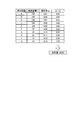
- FIG. 1 is a diagram illustrating an example of various types of information in a circuit to be estimated.
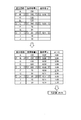
- FIG. 2 is a schematic diagram illustrating an example of power consumption estimation processing performed by the power consumption estimation apparatus according to the first embodiment.
- FIG. 3 is a diagram for explaining a power consumption calculation method for grouping the partial circuits.
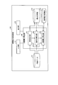
- FIG. 4 is a diagram illustrating the configuration of the power consumption estimation apparatus according to the first embodiment.
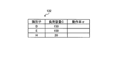
- FIG. 5 is a diagram illustrating an example of the sample storage unit updated by the sample extraction unit.
- FIG. 6 is a diagram illustrating an example of the sample storage unit updated by the operation rate calculation unit.
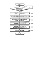
- FIG. 7 is a flowchart illustrating the power consumption estimation processing procedure performed by the power consumption estimation apparatus according to the first embodiment.
- FIG. 1 is a diagram illustrating an example of various types of information in a circuit to be estimated.
- FIG. 2 is a schematic diagram illustrating an example of power consumption estimation processing performed by the power consumption estimation apparatus according to the first embodiment.
- FIG. 3 is
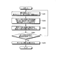
- FIG. 8 is a flowchart illustrating a power consumption calculation processing procedure by the power consumption calculation unit.
- FIG. 9 is a diagram illustrating an example of various types of information in a circuit to be estimated.
- FIG. 10 is a schematic diagram illustrating an example of power consumption estimation processing performed by the power consumption estimation apparatus according to the second embodiment.
- FIG. 11 is a diagram illustrating the configuration of the power consumption estimation apparatus according to the second embodiment.
- FIG. 12 is a diagram illustrating an example of the exception circuit storage unit.
- FIG. 13 is a flowchart illustrating the power consumption estimation processing procedure performed by the power consumption estimation apparatus according to the second embodiment.
- FIG. 14 is a diagram illustrating a computer that executes a power consumption estimation program.
- the power consumption estimation apparatus calculates the load capacity of all partial circuits included in the circuit and calculates the operation rate of some partial circuits included in the circuit when estimating the dynamic power of the circuit. To do. Subsequently, the power consumption estimation apparatus determines the operation rate of the partial circuit for which the operation rate is not calculated as one of the operation rates calculated above. Then, the power consumption estimation device calculates the dynamic power of the circuit by substituting the load capacity and operation rate of each partial circuit into the above equation (1).
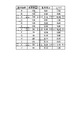
- FIG. 1 is a diagram illustrating an example of various types of information in a circuit to be estimated.
- FIG. 1 shows an example in which a circuit for power estimation includes 10 partial circuits A to J.
- the load capacity C and the operation rate ⁇ are calculated for all the partial circuits A to J.
- the dynamic power of the circuit is calculated by multiplying the operation rate ⁇ and the load capacity C for each partial circuit and calculating the sum of the multiplication results.
- the power consumption estimation apparatus calculates the operation rate for only some partial circuits among the partial circuits included in the estimation target circuit, and calculates the calculated operation rates for the other partial circuits. Divert. Specifically, the power consumption estimation device first calculates the load capacity C of all the partial circuits included in the estimation target circuit. Subsequently, the power consumption estimation apparatus extracts some partial circuits from all the partial circuits. At this time, the power consumption estimation apparatus extracts the partial circuits so that the load capacity values are dispersed.
- the partial circuit extracted by the power consumption estimation apparatus is referred to as a “sample circuit list”.
- the power consumption estimation device calculates the operation rate of the partial circuit extracted as the sample circuit list. Subsequently, the power consumption estimation apparatus determines the operation rate ⁇ of the partial circuit not included in the sample circuit list. Specifically, when determining the operation rate of a partial circuit that is not included in the sample circuit list, the power consumption estimation device first determines a value closest to the load capacity of the partial circuit for which the operation rate is to be determined from the sample circuit list. Select a partial circuit with. Subsequently, the power consumption estimation apparatus sets the operation rate of the selected partial circuit as the operation rate of the partial circuit whose operation rate is to be determined. In this way, the power consumption estimation apparatus calculates and determines the operation rate of each partial circuit, and then calculates the dynamic power of the circuit using the above equation (1).
- each partial circuit in the circuit so that the operation rate ⁇ decreases if the load capacity C is large, and conversely, if the operation rate ⁇ of the partial circuit is large, the load capacitance C decreases. Design to be. Therefore, as in the example shown in FIG. 1, each partial circuit generally has a smaller operation rate ⁇ as the load capacitance C increases. This is because, as can be seen from the above equation (1), in order to reduce the dynamic power, it is required to reduce the value of “operation rate ⁇ ⁇ load capacity C”.
- the load capacity C and the operation rate ⁇ of each partial circuit are in a linear relationship. That is, as described above, even when the operation rate is calculated for only some partial circuits and the operation rate of the partial circuit whose load capacity is approximated for other partial circuits, the calculated dynamic power is accurate. Value. This point will be described in detail below with an example.
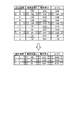
- FIG. 2 is a schematic diagram illustrating an example of power consumption estimation processing performed by the power consumption estimation apparatus according to the first embodiment. 2 illustrates an example in which the power consumption estimation apparatus calculates dynamic power of the circuit illustrated in FIG.
- the power consumption estimation apparatus first calculates “150”, “150”,..., “15”, “10” as the load capacities C of the partial circuits A to J, respectively. . Subsequently, the power consumption estimation apparatus extracts a sample circuit list from the partial circuits A to J. In the example illustrated in FIG. 2, the power consumption estimation apparatus extracts the partial circuits B, E, and H. In FIG. 2, the partial circuits corresponding to the sample circuit list are indicated by hatching. Subsequently, the power consumption estimation apparatus calculates “0.02”, “0.03”, and “0.11” as the operation rates of the extracted partial circuits B, E, and H, respectively.
- the power consumption estimation apparatus determines the operation rate ⁇ of the partial circuits A, C, D, F, G, I, and J that are not included in the sample circuit list. Specifically, when determining the operation rate ⁇ of the partial circuit A, the power consumption estimation apparatus selects the partial circuit B having the load capacity value closest to the load capacity “150” of the partial circuit A from the sample circuit list. select. Then, the power consumption estimation apparatus determines the operation rate “0.02” of the selected partial circuit B as the operation rate of the partial circuit A.
- the power consumption estimation apparatus selects the partial circuit B having the load capacity value closest to the load capacity “130” of the partial circuit C, and sets the operation rate “0.02” of the selected partial circuit B to the partial circuit C. Operating rate.
- the power consumption estimation apparatus determines the operation rate ⁇ from the operation rate of the partial circuit having the closest load capacitance value.
- the power consumption estimation apparatus sets the product “ ⁇ ⁇ C” of the load capacity and the operation rate of the partial circuits A to J to “3.00”, “3.00”,. 65 ”and“ 1.10 ”are calculated. Subsequently, the power consumption estimation apparatus calculates “25.55” as the sum of “ ⁇ ⁇ C”. Then, the power consumption estimation apparatus calculates the dynamic power of the circuit by substituting the power supply voltage V, the operating frequency f, and the calculated sum of “ ⁇ ⁇ C” into the above equation (1).
- Partial circuit A +1.50 Partial circuit C: +1.30 Partial circuit D: No error Partial circuit F: -3.50 Partial circuit G: +0.30 Partial circuit I: -0.60 Partial circuit J: -0.10
- the value of “ ⁇ ⁇ C” of each partial circuit calculated by the power consumption estimation apparatus of the first embodiment includes an error compared to the value calculated by the method of FIG.
- the power consumption estimation device determines the operation rates of the partial circuits A, C, D, F, G, I, and J by the load of each partial circuit. Since the operation rate of the partial circuit having the value closest to the capacitance is used, the sum of “ ⁇ ⁇ C” is expected to have a small error.
- the error of the partial circuit A is “+1.50”, but the error of the partial circuit F is “ ⁇ 3.50”. That is, when “ ⁇ ⁇ C” is summed, errors in the partial circuits are canceled out.
- the sum of “ ⁇ ⁇ C” calculated by the power consumption estimation apparatus is only “1.00” smaller than the sum of “ ⁇ ⁇ C” shown in FIG.
- the number of partial circuits is small. However, if the number of partial circuits is large as in an actual circuit, the error of the sum of “ ⁇ ⁇ C” becomes smaller. It can be ignored.
- FIG. 3 is a diagram for explaining a power consumption calculation method for grouping the partial circuits.
- FIG. 3 illustrates an example in which dynamic power is calculated for a circuit similar to the circuit illustrated in FIG.
- the partial circuits A to J are divided into a group G1 including the partial circuits A, C, E, G, and I and a group G2 including the partial circuits B, D, F, H, and J. Shall be.
- “0.060” is calculated as the operation rate ⁇ in the group G1
- “0.072” is calculated as the operation rate ⁇ in the group G2.
- the sum of “ ⁇ ⁇ C” of each partial circuit is “52.14”. That is, in the case of the method shown in FIG. 3, the total sum of “ ⁇ ⁇ C” is “25.49” larger than the value calculated by the method of FIG.
- the power consumption estimation apparatus uses a partial circuit as a sample circuit list among all the partial circuits included in the circuit to be estimated, and is included in the sample circuit list. The operation rate is actually calculated only for the circuit. Then, the power consumption estimation apparatus sets the operation rate of the partial circuit not included in the sample circuit list as the operation rate of the partial circuit on the sample circuit list having a value closest to the load capacity of each partial circuit. Thereby, the power consumption estimation apparatus can speed up the process of calculating the operation rate of each partial circuit, and as a result, can calculate dynamic power at high speed.
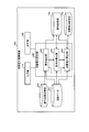
- FIG. 4 is a diagram illustrating the configuration of the power consumption estimation apparatus 100 according to the first embodiment.
- the power consumption estimation apparatus 100 includes an input unit 110, an output unit 120, circuit data 131, a sample storage unit 132, a power consumption storage unit 133, and a power consumption calculation unit 140.
- FIG. 4 shows only the configuration related to the process of calculating dynamic power.
- the input unit 110 is an input device for inputting various information and operation instructions, for example, a keyboard and a mouse.
- the output unit 120 is an output device that outputs various types of information, and is, for example, a liquid crystal display or a speaker.
- the circuit data 131 stores various information related to the circuit to be estimated.
- the circuit data 131 stores a circuit configuration, wiring, and the like for each partial circuit.
- 4 shows an example in which the power consumption estimation apparatus 100 has the circuit data 131, the power consumption estimation apparatus 100 may accept circuit data from an external device.
- the sample storage unit 132 stores an identifier for identifying a partial circuit, a load capacity of the partial circuit, and an operation rate of the partial circuit in association with each other for some partial circuits included in the circuit. Note that the configuration and the like of the sample storage unit 132 will be described while explaining the power consumption calculation unit 140.
- the power consumption storage unit 133 stores the power consumption calculated by the power consumption calculation unit 140.
- the power consumption calculation unit 140 controls the power consumption calculation process, and includes a sample extraction unit 141, an operation rate calculation unit 142, and a power consumption calculation unit 143.
- the sample extraction unit 141 extracts a sample circuit list from the partial circuit included in the circuit to be estimated. Specifically, the sample extraction unit 141 first reads information on the circuit to be estimated from the circuit data 131. Subsequently, the sample extraction unit 141 calculates the load capacity for all the partial circuits included in the circuit read from the circuit data 131. Subsequently, the sample extraction unit 141 rearranges the partial circuits in ascending order or descending order of the load capacity. Subsequently, the sample extraction unit 141 extracts partial circuits at predetermined intervals from the rearranged partial circuits. Then, the sample extraction unit 141 stores the identifier indicating the extracted partial circuit and the load capacity of the partial circuit in the sample storage unit 132.
- the sample extraction unit 141 calculates the load capacities of all the partial circuits, but a processing unit other than the sample extraction unit 141 may calculate the load capacities of the partial circuits.
- the power consumption calculation unit 140 or a predetermined processing unit (not shown) included in the power consumption calculation unit 140 may calculate the load capacities of all the partial circuits.
- the sample extraction unit 141 first calculates the load capacities of the partial circuits A to J. Subsequently, the sample extraction unit 141 rearranges the partial circuits in order of decreasing load capacity. Specifically, the sample extraction unit 141 rearranges the partial circuits in the order of the partial circuits A, B,. Subsequently, the sample extraction unit 141 extracts one partial circuit from every three partial circuits A to J. Specifically, the sample extraction unit 141 extracts the partial circuit B from the three partial circuits A to C, extracts the partial circuit E from the three partial circuits D to F, and extracts the three partial circuits G to A partial circuit H is extracted from I.
- the sample extraction unit 141 stores the identifiers indicating the extracted partial circuits B, E, and H in association with the load capacitors C of the partial circuits B, E, and H in the sample storage unit 132.
- FIG. 5 shows an example of the sample storage unit 132 updated by the sample extraction unit 141. As illustrated in FIG. 5, the sample storage unit 132 updated by the sample extraction unit 141 stores an identifier and a load capacity C. In the example illustrated in FIG. 5, the sample storage unit 132 stores load capacities “150”, “100”, and “20” in association with identifiers “B”, “E”, and “H”, respectively.
- the operation rate calculation unit 142 calculates the operation rate of the partial circuit included in the sample circuit list. Specifically, the operation rate calculation unit 142 reads the identifier of the partial circuit from the sample storage unit 132. Subsequently, the operation rate calculation unit 142 calculates the operation rate of the partial circuit indicated by the read identifier. At this time, the operation rate calculation unit 142 calculates the operation rate of each partial circuit by inputting a test pattern to a predetermined simulator or the like. Then, the operation rate calculation unit 142 stores the calculated operation rate in the sample storage unit 132 in association with the target partial circuit.
- the operation rate calculation unit 142 reads the identifiers “B”, “E”, and “H” from the sample storage unit 132 illustrated in FIG. Then, the operation rate calculation unit 142 calculates the operation rates of the partial circuits B, E, and H.
- FIG. 6 shows an example of the sample storage unit 132 updated by the operation rate calculation unit 142.
- 6 shows an example in which the sample storage unit 132 shown in FIG.
- the sample storage unit 132 updated by the operation rate calculation unit 142 stores the operation rate ⁇ in addition to the identifier and the load capacity C.
- the sample storage unit 132 associates the identifiers “B”, “E”, and “H” with the operation rates “0.02”, “0.03”, and “0.11”, respectively. Is memorized.
- the power consumption calculation unit 143 determines the operation rate of the partial circuit not included in the sample circuit list, and then calculates the dynamic power of the circuit to be estimated. Specifically, the power consumption calculation unit 143 first extracts partial circuits that are not included in the sample circuit list. That is, the power consumption calculation unit 143 extracts partial circuits that are not stored in the sample storage unit 132 from the circuit data 131. Subsequently, the power consumption calculation unit 143 selects a partial circuit having a value closest to the load capacity of the extracted partial circuit from the sample circuit list. Subsequently, the power consumption calculation unit 143 determines to set the operation rate of the partial circuit selected from the sample circuit list to the operation rate of the partial circuit extracted from the circuit data 131.
- the power consumption calculation unit 143 calculates the dynamic power of the circuit stored in the circuit data 131 using the above formula (1). Specifically, when processing the partial circuit included in the sample circuit list, the power consumption calculation unit 143 substitutes the load capacity calculated by the sample extraction unit 141 for the load capacity C of the above formula (1), The operation rate calculated by the operation rate calculation unit 142 is substituted into the operation rate ⁇ . On the other hand, when processing a partial circuit not included in the sample circuit list, the power consumption calculation unit 143 substitutes the load capacity calculated by the sample extraction unit 141 for the load capacity C of the above formula (1), and operates. The operation rate determined from the operation rates of the partial circuits on the sample circuit list is substituted into the rate ⁇ . Note that the power consumption calculation unit 143 may acquire the power supply voltage V and the operating frequency f to be substituted into the above equation (1) from the circuit data 131 or from an external device.
- the power consumption calculation unit 143 stores the calculated dynamic power in the power consumption storage unit 133. Note that the power consumption calculation unit 143 may display the dynamic power on the output unit 120 or transmit the dynamic power to another external device.
- the power consumption calculation processing by the power consumption calculation unit 143 will be described using the example shown in FIG. Here, it is assumed that the sample storage unit 132 updated by the operation rate calculation unit 142 is in the state shown in FIG.
- the power consumption calculation unit 143 determines the load capacity “150” of the partial circuit A from the sample circuit list when determining the operation rate ⁇ of the partial circuit A.
- the partial circuit B having a close value is selected.
- the power consumption calculation unit 143 determines to set the operation rate “0.02” of the selected partial circuit B to the operation rate of the partial circuit A.
- the power consumption calculation unit 143 determines the operation rate ⁇ of the partial circuits C, D, F, G, I, and J.
- the power consumption calculation unit 143 substitutes “150”, “100”, and “20” for the load capacity C of the above equation (1), respectively, and the operation rate “0.02”, “0.03”, and “0.11” are assigned to ⁇ , respectively. Further, when processing the partial circuits A, C, D, F, G, I, and J, the power consumption calculation unit 143 adds “150”, “130”, “ “120”, “70”, “30”, “15”, “10” are substituted. Further, when processing the partial circuits A, C, D, F, G, I, and J, the power consumption calculation unit 143 sets “0.02” and “0. “02”, “0.03”, “0.03”, “0.11”, “0.11”, “0.11” are substituted.
- FIG. 7 is a flowchart illustrating the power consumption estimation processing procedure performed by the power consumption estimation apparatus 100 according to the first embodiment.
- Step S101 when an instruction to start the power consumption estimation process is received (Yes in Step S101), the sample extraction unit 141 reads information on the circuit to be estimated from the circuit data 131 (Step S102). .
- the sample extraction unit 141 calculates the load capacities of all the partial circuits included in the read circuit (step S103). Subsequently, the sample extraction unit 141 rearranges the partial circuits in ascending order or descending order of the load capacity (Step S104). Subsequently, the sample extraction unit 141 generates a sample circuit list by extracting partial circuits for each predetermined number from the rearranged partial circuits (step S105). Subsequently, the sample extraction unit 141 stores the identifier of the partial circuit and the load capacity C included in the extracted sample circuit list in the sample storage unit 132.
- the operation rate calculation unit 142 calculates the operation rates of the partial circuits included in the sample circuit list (step S106). Specifically, the operation rate calculation unit 142 reads the identifier from the sample storage unit 132, and calculates the operation rate of the partial circuit indicated by the read identifier. Then, the operation rate calculation unit 142 stores the calculated operation rate in the sample storage unit 132.
- the power consumption calculation unit 143 performs power consumption calculation processing (step S107). Specifically, the power consumption calculation unit 143 calculates the dynamic power of the circuit to be estimated based on the load capacity calculated by the sample extraction unit 141 and various types of information stored in the sample storage unit 132. . The power consumption calculation process by the power consumption calculation unit 143 will be described in detail with reference to FIG.
- FIG. 8 is a flowchart showing a power consumption calculation processing procedure by the power consumption calculation unit 143.
- the power consumption calculation unit 143 first reads one partial circuit not included in the sample circuit list from the circuit data 131 (step S201). Subsequently, the power consumption calculation unit 143 selects a partial circuit having a value closest to the load capacity of the partial circuit extracted in step S201 from the sample circuit list (step S202). Subsequently, the power consumption calculation unit 143 determines to set the operation rate of the partial circuit selected in S202 to the operation rate of the extracted partial circuit (step S203).
- the power consumption calculation unit 143 determines that the operation rate is not determined from the circuit data 131 when the operation rate is not determined for all the partial circuits not included in the sample circuit list (No in step S204), and Then, one partial circuit not included in the sample circuit list is extracted (step S201).
- the subsequent processing is the same as the processing procedure in steps S202 and S203 described above.
- the power consumption calculation unit 143 uses the above formula (1) to calculate the circuit to be estimated. Dynamic power is calculated (step S205).
- the power consumption calculation unit 143 substitutes the load capacity of each partial circuit calculated by the sample extraction unit 141 for the load capacity C of the above equation (1).
- the power consumption calculation unit 143 substitutes the operation rate calculated by the operation rate calculation unit 142 for the operation rate ⁇ in the above equation (1).
- the power consumption calculation unit 143 substitutes the operation rate determined in the processing procedure in step S203 for the operation rate ⁇ of the above equation (1).
- the power consumption estimation apparatus 100 As described above, the power consumption estimation apparatus 100 according to the first embodiment generates a sample circuit list by extracting some partial circuits from the circuit to be estimated, and the partial circuits included in the sample circuit list. Only the operation rate is calculated, and the calculated operation rate is stored in the sample storage unit 132. Then, the power consumption estimation apparatus 100 calculates the dynamic power of the estimation target circuit after determining the operation rate of the partial circuit not included in the sample circuit list using the operation rate stored in the sample storage unit 132. To do. Thereby, the power consumption estimation apparatus 100 can speed up the process of calculating the operation rate of each partial circuit, and as a result, can calculate dynamic power at high speed.
- the power consumption estimation apparatus 100 sorts all partial circuits in ascending or descending order of load capacity, extracts partial circuits for each predetermined number from the sorted partial circuits, and a sample circuit list. Is generated. Then, the power consumption estimation apparatus 100 sets the operation rate of the partial circuit not included in the sample circuit list as the operation rate of the partial circuit having a value closest to the load capacity of the partial circuit. Thereby, the power consumption estimation apparatus 100 can reduce the error of the sum total of “operation rate ⁇ ⁇ load capacity C” in the partial circuit. That is, the power consumption estimation apparatus 100 can calculate the dynamic power of the estimation target circuit at high speed and with high accuracy.
- the load capacity and the operation rate have a linear relationship with respect to each partial circuit.
- FIG. 9 is a diagram illustrating an example of various types of information in a circuit to be estimated.
- FIG. 10 is a schematic diagram illustrating an example of power consumption estimation processing performed by the power consumption estimation apparatus according to the second embodiment.
- partial circuits X, Y, and Z are added to the partial circuits A to J shown in FIG.
- the value of the load capacitance C is “140”
- the value of the operation rate ⁇ is “0.12.” That is, the partial circuit X has a larger load capacity C and a higher operation rate ⁇ than the partial circuits A to J.
- the partial circuit Y also has a relatively large load capacitance C and a relatively large operating rate ⁇ .
- the partial circuit Z has a relatively small load capacity C and a relatively small operation rate ⁇ . That is, in the example shown in FIG. 9, the partial circuits X, Y, and Z and the partial circuits A to J are not in a linear relationship.
- the power consumption estimation apparatus calculates the operation rate separately for the partial circuits A to J and the partial circuits X, Y, and Z.
- the power consumption estimation process by the power consumption estimation device will be described using the example shown in FIG.
- the power consumption estimation apparatus first removes the partial circuits X to Z from the partial circuits A to J and X to Z. It is assumed that the power consumption estimation apparatus recognizes in advance partial circuits X to Z that are not in a linear relationship based on the history of power consumption estimation processing performed in the past.
- the power consumption estimation apparatus calculates the operation rates of the partial circuits A to J using the method described in the first embodiment. Specifically, as shown in FIG. 10, the power consumption estimation apparatus extracts the partial circuits B, E, and H as the sample circuit list from the partial circuits A to J, and extracts the extracted partial circuits B, E, and H. Calculate the operation rate. Subsequently, the power consumption estimation apparatus calculates the operation rates of the partial circuits A, C, D, F, G, I, and J that are not included in the sample circuit list and the partial circuits B, E, and H included in the sample circuit list. Decide on one of the operating rates.
- the power consumption estimation device calculates the operation rate of each of the partial circuits X to Z.
- the power consumption estimation apparatus calculates “0.12”, “0.20”, and “0.01” as the operation rates of the partial circuits X, Y, and Z, respectively.
- the power consumption estimation device substitutes the dynamic capacity of the circuit stored in the circuit data 131 by substituting the load capacity C and the operation rate ⁇ of the partial circuits A to J and X to Z into the above equation (1). Is calculated.
- the power consumption estimation apparatus classifies the partial circuit in which the load capacitance C and the operation rate ⁇ are in a linear relationship and the partial circuit in which the load rate C is not in a linear relationship, and separately determines the operation rate. calculate.
- the power consumption estimation apparatus performs a process of calculating the operation rate of each partial circuit even when there is a partial circuit where the load capacity C and the operation rate ⁇ are not in a linear relationship. The speed can be increased.
- the power consumption estimation apparatus can calculate the dynamic power with high accuracy even when there is a partial circuit where the load capacity C and the operation rate ⁇ are not in a linear relationship.
- FIG. 11 is a diagram illustrating the configuration of the power consumption estimation apparatus 200 according to the second embodiment.
- parts having the same functions as the constituent parts shown in FIG. 4 are denoted by the same reference numerals, and detailed description thereof is omitted.
- the power consumption estimation apparatus 200 has circuit data 231. Similarly to the circuit data 131, the circuit data 231 stores various types of information regarding the circuit to be estimated. Here, it is assumed that the circuit data 231 stores information on circuits including the partial circuits A to J and X to Z shown in FIG.
- the power consumption estimation apparatus 200 includes an exception circuit storage unit 234.
- the exception circuit storage unit 234 stores various types of information regarding partial circuits (hereinafter referred to as “exception circuits”) in which the load capacity and the operation rate are not in a linear relationship. In other words, the exception circuit storage unit 234 stores partial circuits that are not candidates for the sample circuit list.
- FIG. 12 shows an example of the exception circuit storage unit 234.
- the exception circuit storage unit 234 has an item such as an exception circuit.
- exception circuit identifiers of partial circuits that are not candidates for the sample circuit list are stored.
- identifiers “X” to “Z” of the partial circuits X to Z are stored. Note that the exception circuit is specified in advance based on the history of power consumption estimation processing performed in the past.
- the power consumption estimation apparatus 200 includes a power consumption calculation unit 240.
- the power consumption calculation unit 240 includes a sample extraction unit 241, an operation rate calculation unit 242, and a power consumption calculation unit 243.
- the sample extraction unit 241 reads information on the circuit to be estimated from the circuit data 231. Subsequently, the sample extraction unit 241 calculates the load capacities of all the partial circuits included in the read circuit. Subsequently, the sample extraction unit 241 excludes the exception circuit stored in the exception circuit storage unit 234 from the partial circuit included in the read circuit. Subsequently, the sample extraction unit 241 performs the same process as the process described in the first embodiment on the partial circuit excluding the exception circuit.
- the sample extraction unit 241 first calculates the load capacities of the partial circuits A to J and X to Z. Subsequently, the sample extraction unit 241 removes the partial circuits X to Z stored in the exception circuit storage unit 234 from the partial circuits A to J and X to Z. Subsequently, the sample extraction unit 241 rearranges the partial circuits A to J in ascending or descending order of the load capacity, and extracts partial circuits from the rearranged partial circuits A to J at a predetermined interval.
- the sample extraction unit 241 stores the identifier indicating the extracted partial circuits B, E, and H and the load capacity C of the partial circuits B, E, and H in the sample storage unit 132.
- the operation rate calculation unit 242 reads the identifiers of the partial circuits B, E, and H from the sample storage unit 132, and calculates the operation rate of the partial circuit indicated by the read identifier. Then, the operation rate calculation unit 242 stores the calculated operation rate in the sample storage unit 132. Further, the operation rate calculation unit 242 calculates the operation rate of the exception circuit excluded by the sample extraction unit 241.
- the operation rate calculation unit 242 calculates the operation rates of the partial circuits B, E, and H stored in the sample storage unit 132.
- the operation rate calculation unit 242 calculates the operation rates of the partial circuits X to Z that are exceptional circuits.
- the operation rate calculation unit 242 uses “0.12”, “0.20”, and “0.01” as the operation rates of the partial circuits X, Y, and Z, respectively, as in the example illustrated in FIG. Is calculated.
- the power consumption calculation unit 243 determines the operation rate of the partial circuit that is not included in the sample circuit list among the partial circuits from which the exception circuit is removed, and then stores the operation rate in the circuit data 231 using the above equation (1). Calculate the dynamic power of the circuit being connected.
- the power consumption calculation unit 243 performs the same processing as the processing described in the first embodiment, thereby operating the operation rates of the partial circuits A, C, D, F, G, I, and J. ⁇ is determined.
- the power consumption calculation unit 243 substitutes “150”, “150”,..., “10” for the load capacity C of the above equation (1), respectively. “0.02”, “0.02”,..., “0.11” are assigned to the operation rate ⁇ .
- the power consumption calculation unit 243 substitutes “140”, “90”, and “10” for the load capacity C of the above equation (1), respectively, and the operation rate “0.12”, “0.20”, and “0.01” are assigned to ⁇ , respectively.
- FIG. 13 is a flowchart illustrating the power consumption estimation processing procedure performed by the power consumption estimation apparatus 200 according to the second embodiment.
- Step S ⁇ b> 301 when an instruction to start processing is received (Yes at Step S ⁇ b> 301), the sample extraction unit 241 reads information on a circuit to be estimated from the circuit data 231 (Step S ⁇ b> 302).
- the sample extraction unit 241 calculates the load capacities of all the partial circuits included in the read circuit (Step S303). Subsequently, the sample extraction unit 241 removes the exception circuit stored in the exception circuit storage unit 234 from the partial circuit included in the read circuit (step S304).
- the sample extraction unit 241 rearranges the partial circuits from which the exception circuit is removed in ascending order or descending order of the load capacity (step S305). Subsequently, the sample extraction unit 241 generates a sample circuit list by extracting partial circuits for each predetermined number from the rearranged partial circuits (step S306). Subsequently, the sample extraction unit 241 stores the identifier of the partial circuit and the load capacity C included in the extracted sample circuit list in the sample storage unit 132.
- the operation rate calculation unit 242 calculates the operation rates of the partial circuits included in the sample circuit list (step S307). Then, the operation rate calculation unit 242 stores the calculated operation rate in the sample storage unit 132. Further, the operating rate calculation unit 242 calculates the operating rate of the exception circuit (step S308).
- the power consumption calculation unit 243 performs power consumption calculation processing (step S309). Specifically, the power consumption calculation unit 243 calculates the dynamic power of the circuit to be estimated based on the load capacity calculated by the sample extraction unit 241 and the operation rate calculated by the operation rate calculation unit 242. .
- the power consumption calculation processing procedure by the power consumption calculation unit 243 is the same as the processing procedure shown in FIG.
- the power consumption estimation apparatus 200 according to the second embodiment classifies the partial circuit in which the load capacity C and the operation rate ⁇ are in a linear relationship from the partial circuit in which the load rate C is not in a linear relationship. Is calculated. As a result, the power consumption estimation apparatus 200 according to the second embodiment increases the dynamic power of the circuit to be estimated at high speed even when there is a partial circuit in which the load capacity C and the operation rate ⁇ are not in a linear relationship. It can be calculated with high accuracy.
- the various processes described in the first and second embodiments can be realized by executing a prepared program on a computer such as a personal computer or a workstation. Therefore, in the following, an example of a computer that executes a power consumption estimation program having the same function as that of the power consumption estimation apparatus 200 in the second embodiment will be described with reference to FIG.
- FIG. 14 is a diagram illustrating a computer that executes a power consumption estimation program.
- a RAM Random Access Memory
- a cache 1020 In a computer 1000, a RAM (Random Access Memory) 1010, a cache 1020, an HDD 1030, a ROM (Read Only Memory) 1040, and a CPU 1050 are connected by a bus 1060.
- a bus 1060 As shown in FIG. 14, in a computer 1000, a RAM (Random Access Memory) 1010, a cache 1020, an HDD 1030, a ROM (Read Only Memory) 1040, and a CPU 1050 are connected by a bus 1060.
- a bus 1060 As shown in FIG. 14, in a computer 1000, a RAM (Random Access Memory) 1010, a cache 1020, an HDD 1030, a ROM (Read Only Memory) 1040, and a CPU 1050 are connected by a bus 1060.
- the ROM 1040 stores in advance a power consumption estimation program that exhibits the same function as the power consumption estimation apparatus 100 in the first embodiment. Specifically, the ROM 1040 stores a sample extraction program 1041, an operation rate calculation program 1042, and a power consumption calculation program 1043.
- the CPU 1050 reads and executes the sample extraction program 1041, the operation rate calculation program 1042, and the power consumption calculation program 1043. Accordingly, as illustrated in FIG. 14, the sample extraction program 1041 becomes the sample extraction process 1051, the operation rate calculation program 1042 becomes the operation rate calculation process 1052, and the power consumption calculation program 1043 becomes the power consumption calculation process 1053. become.
- the sample extraction process 1051 corresponds to the sample extraction unit 141 shown in FIG. 4, the operation rate calculation process 1052 corresponds to the operation rate calculation unit 142 shown in FIG. 4, and the power consumption calculation process 1053 4 corresponds to the power consumption calculation unit 143 shown in FIG.
- the HDD 1030 is provided with circuit data 1031 and a sample list 1032 as shown in FIG.
- the circuit data 1031 corresponds to the circuit data 131 shown in FIG. 4, and the sample list 1032 corresponds to the sample storage unit 132 shown in FIG.
- the programs 1041 to 1043 are not necessarily stored in the ROM 1040.
- the program 1041 or the like may be stored in a “portable physical medium” such as a flexible disk (FD), a CD-ROM, an MO disk, a DVD disk, a magneto-optical disk, or an IC card inserted into the computer 1000.
- the program 1041 or the like may be stored in a “fixed physical medium” such as a hard disk drive (HDD) provided inside or outside the computer 1000.
- the program 1041 or the like may be stored in “another computer (or server)” connected to the computer 1000 via a public line, the Internet, a LAN, a WAN, or the like.
- the computer 1000 may read and execute each program from the above-described flexible disk or the like.
Landscapes
- Engineering & Computer Science (AREA)
- Computer Hardware Design (AREA)
- Physics & Mathematics (AREA)
- Theoretical Computer Science (AREA)
- Evolutionary Computation (AREA)
- Geometry (AREA)
- General Engineering & Computer Science (AREA)
- General Physics & Mathematics (AREA)
- Design And Manufacture Of Integrated Circuits (AREA)
Abstract
ダイナミック電力を高速に算出することができる消費電力見積装置、消費電力見積プログラム及び消費電力見積方法を提供することを課題とする。見積もり対象の回路から一部の部分回路を抽出して標本回路リストを生成し、標本回路リストに含まれている部分回路についてのみ動作率を算出し、算出した動作率を標本記憶部に記憶させる。そして、標本記憶部に記憶されている動作率を用いて、標本回路リストに含まれない部分回路の動作率を決定した後に、見積もり対象の回路のダイナミック電力を算出する。
Description
本発明は、消費電力見積装置、消費電力見積プログラム及び消費電力見積方法に関する。
従来、情報処理装置の熱設計や電源設計を最適化するために、LSI(Large Scale Integration)などの回路を設計する工程において、設計した回路の消費電力を見積もることがある。このときに見積もられる消費電力には、回路の動作に関係なく電源を投入しただけで消費されるスタティック電力と、回路が動作することによって消費されるダイナミック電力が含まれる。一般に、ダイナミック電力(pdynamic)は、以下に示す式(1)によって算出される。

上記式(1)において、Vは電源電圧を示し、fは動作周波数を示し、αは動作率を示し、Cは回路の負荷容量を示す。なお、動作率αは、単位時間当たりに、回路内の内部配線の電位が「0」→「1」もしくは「1」→「0」に変化する割合を示す。
上記式(1)によってダイナミック電力を算出する場合、消費電力見積もり対象の回路を複数の回路に区切る。そして、区切られた回路(以下、「部分回路」と言う)の配線ごとに、動作率αと負荷容量Cとの積が算出される。ダイナミック電力は、上記式(1)中の「Σ(α×C)」に示すように、部分回路ごとに動作率αと負荷容量Cとが乗算され、各部分回路における「α×C」が総和されることにより算出される。
また、ダイナミック電力を複数回算出する場合に、2回目以降の処理を簡易にする技術が知られている。かかる技術では、1回目の処理において算出した部分回路ごとの負荷容量と動作率とに基づいて、負荷容量と動作率との関連を示す情報を作成し、かかる関連情報を2回目以降の処理に用いる。
しかしながら、上述した従来技術には、ダイナミック電力を算出する処理に時間がかかるという問題があった。具体的には、上記の従来技術では、ダイナミック電力を算出する場合に、部分回路ごとに動作率と負荷容量とを求める。一般に、全ての配線の負荷容量を算出する処理は高速であるが、全ての配線の動作率を算出する処理は時間がかかる。これは、負荷容量は、回路の実装設計データから求められるが、動作率は、シミュレータ等にテストパターンを入力することによって求められるからである。このように、全ての配線の動作率を算出する処理に時間がかかるので、上記の従来技術は、ダイナミック電力を算出する処理に時間がかかる。
また、動作率の測定時間は、ネット数やシミュレーション上での計測時間に比例して増大する。このため、例えば、CPU(Central Processing Unit)などの非常に大規模な回路(数千万ゲート以上)の場合、LSI全体の配線の動作率を求めて個々の配線ごとに消費電力を計算するためには、多くの時間と計算機資源を用いることになる。
ここで、いくつかの部分回路ごとに回路をグループ分けして、グループごとに動作率を算出することも考えられる。しかし、電源電圧及び動作周波数がLSI全体で一定であるとした場合、LSI設計における精度の高いダイナミック電力予測のためには、LSI内部の全ての配線に対して個別に動作率及び負荷容量を求めることが望ましい。
また、1回目の処理において算出した負荷容量及び動作率を、2回目以降における処理に用いる技術は、あくまで消費電力を複数回算出することが前提となっており、1回目に消費電力を算出する時間を短くすることはできない。
開示の技術は、上述した従来技術による問題点を解消するためになされたものであり、ダイナミック電力を高速に算出することができる消費電力見積装置、消費電力見積プログラム及び消費電力見積方法を提供することを目的とする。
上述した課題を解決し、目的を達成するために、本願に開示する消費電力見積装置は、複数の部分回路に区切られた回路のうち一部の部分回路について、該部分回路を識別する識別子と、該部分回路の負荷容量と、該部分回路の動作率とを対応付けて記憶する標本記憶部と、前記複数の部分回路のうち、部分回路を示す識別子が前記標本記憶部に記憶されている場合に、該識別子に対応付けて前記標本記憶部に記憶されている動作率に基づいて該部分回路の消費電力を算出し、前記複数の部分回路のうち、部分回路を示す識別子が前記標本記憶部に記憶されていない場合に、該部分回路の負荷容量に最も近い負荷容量に対応付けて前記標本記憶部に記憶されている動作率に基づいて該部分回路の消費電力を算出する消費電力算出部とを備えたことを要件とする。
なお、本願に開示する消費電力見積装置の構成要素、表現または構成要素の任意の組合せを、方法、装置、システム、コンピュータプログラム、記録媒体、データ構造などに適用したものも、他の態様として有効である。
本願に開示した消費電力見積装置によれば、ダイナミック電力を高速に算出することができるという効果を奏する。
100、200 消費電力見積装置
110 入力部
120 出力部
131、231 回路データ
132 標本記憶部
133 消費電力記憶部
140、240 消費電力算出部
141、241 標本抽出部
142、242 動作率算出部
143、243 消費電力算出部
234 例外回路記憶部
1000 コンピュータ
1020 キャッシュ
1030 HDD
1031 回路データ
1032 標本リスト
1040 ROM
1041 標本抽出プログラム
1042 動作率算出プログラム
1043 消費電力算出プログラム
1050 CPU
1051 標本抽出プロセス
1052 動作率算出プロセス
1053 消費電力算出プロセス
1060 バス
110 入力部
120 出力部
131、231 回路データ
132 標本記憶部
133 消費電力記憶部
140、240 消費電力算出部
141、241 標本抽出部
142、242 動作率算出部
143、243 消費電力算出部
234 例外回路記憶部
1000 コンピュータ
1020 キャッシュ
1030 HDD
1031 回路データ
1032 標本リスト
1040 ROM
1041 標本抽出プログラム
1042 動作率算出プログラム
1043 消費電力算出プログラム
1050 CPU
1051 標本抽出プロセス
1052 動作率算出プロセス
1053 消費電力算出プロセス
1060 バス
以下に、本願に開示する消費電力見積装置、消費電力見積プログラム及び消費電力見積方法の実施例を図面に基づいて詳細に説明する。なお、この実施例により本願に開示する消費電力見積装置、消費電力見積プログラム及び消費電力見積方法が限定されるものではない。なお、以下の実施例において、「回路の負荷容量」と表記する場合、「回路内の配線及び回路素子の負荷容量」を示すものとする。
[実施例1に係る消費電力見積装置による消費電力見積処理]
まず、実施例1に係る消費電力見積装置による消費電力見積処理について説明する。実施例1に係る消費電力見積装置は、回路のダイナミック電力を見積もる場合に、回路に含まれる全ての部分回路の負荷容量を算出するとともに、回路に含まれる一部の部分回路の動作率を算出する。続いて、消費電力見積装置は、動作率が算出されていない部分回路の動作率を、前述において算出した動作率のいずれかに決定する。そして、消費電力見積装置は、各部分回路の負荷容量及び動作率を上記式(1)に代入することにより、回路のダイナミック電力を算出する。
まず、実施例1に係る消費電力見積装置による消費電力見積処理について説明する。実施例1に係る消費電力見積装置は、回路のダイナミック電力を見積もる場合に、回路に含まれる全ての部分回路の負荷容量を算出するとともに、回路に含まれる一部の部分回路の動作率を算出する。続いて、消費電力見積装置は、動作率が算出されていない部分回路の動作率を、前述において算出した動作率のいずれかに決定する。そして、消費電力見積装置は、各部分回路の負荷容量及び動作率を上記式(1)に代入することにより、回路のダイナミック電力を算出する。
図1及び図2を用いて、消費電力見積装置による消費電力見積処理を具体的に説明する。図1は、見積もり対象の回路における各種情報の一例を示す図である。図1では、電力見積もり対象の回路が、10個の部分回路A~Jを含む例を示している。
ここで、図1の例では、全ての部分回路A~Jについて、負荷容量Cと動作率αとを算出している。そして、図1の例では、部分回路ごとに、動作率αと負荷容量Cとを乗算し、乗算した結果の総和を算出することにより、回路のダイナミック電力を算出している。
図1に示した例では、部分回路A~Jの負荷容量Cとして、それぞれ「150」、「150」、・・・、「15」、「10」を算出する。また、図1の例では、部分回路A~Jの動作率αとして、それぞれ「0.01」、「0.02」、・・・、「0.15」、「0.12」を算出する。続いて、図1の例では、部分回路A~Jの各々の負荷容量と動作率とを乗算して、「α×C」として、それぞれ「1.50」、「3.00」、・・・、「2.25」、「1.20」を算出する。続いて、図1の例では、「α×C」の総和として、「26.65」を算出する。そして、図1の例では、上記式(1)に示すように、電源電圧Vと、動作周波数fと、算出された「α×C」の総和を用いて、回路のダイナミック電力を算出する。
しかし、上述した例では、各部分回路の動作率αを算出する処理に時間がかかることが原因で、ダイナミック電力を算出する処理に時間がかかるという問題や、多くの計算機資源を要するという問題が発生していた。なお、図1に示した例では、説明を簡単にするために、部分回路の数が10個である例を示したが、実際には、数千万ゲート以上の大規模な回路も存在する。したがって、図1の例は、実際には、数万以上の部分回路について動作率を算出することになるので、膨大な時間や計算機資源を要していた。
そこで、実施例1に係る消費電力見積装置は、見積もり対象の回路に含まれる部分回路のうち、一部の部分回路についてだけ動作率を算出し、他の部分回路については算出された動作率を流用する。具体的には、消費電力見積装置は、まず、見積もり対象の回路に含まれる全ての部分回路の負荷容量Cを算出する。続いて、消費電力見積装置は、全ての部分回路から、一部の部分回路を抽出する。このとき、消費電力見積装置は、負荷容量の値が分散するように、部分回路を抽出する。なお、以下では、消費電力見積装置によって抽出された部分回路を「標本回路リスト」と呼ぶこととする。
続いて、消費電力見積装置は、標本回路リストとして抽出した部分回路の動作率を算出する。続いて、消費電力見積装置は、標本回路リストに含まれない部分回路の動作率αを決定する。具体的には、消費電力見積装置は、標本回路リストに含まれない部分回路の動作率を決定する場合に、まず、標本回路リストから、動作率決定対象の部分回路の負荷容量に最も近い値を持つ部分回路を選択する。続いて、消費電力見積装置は、選択した部分回路の動作率を、動作率決定対象の部分回路の動作率とする。このようにして、消費電力見積装置は、各部分回路の動作率を算出及び決定した後に、上記式(1)を用いて回路のダイナミック電力を算出する。
ここで、上記の手法によって負荷容量を決定する理由を説明する。一般に、設計者は、回路内の各部分回路について、負荷容量Cが大きければ、動作率αが小さくなるように設計し、反対に、部分回路の動作率αが大きければ、負荷容量Cが小さくなるように設計する。したがって、図1に示した例のように、各部分回路は、負荷容量Cが大きいほど動作率αが小さくなることが一般的である。これは、上記式(1)から分かるように、ダイナミック電力を小さくするためには、「動作率α×負荷容量C」の値を小さくすることが求められるからである。
このため、一般に、各部分回路の負荷容量Cと動作率αとは線形の関係にある。すなわち、上記のように、一部の部分回路だけ動作率を算出して、他の部分回路については負荷容量が近似する部分回路の動作率を用いても、算出されるダイナミック電力は精度の良い値になる。かかる点について、以下に例を挙げて詳細に説明する。
図2を用いて、実施例1に係る消費電力見積装置による消費電力見積処理の一例を説明する。図2は、実施例1に係る消費電力見積装置による消費電力見積処理の一例を説明するための図である。なお、図2では、消費電力見積装置が、図1に示した回路のダイナミック電力を算出する例を示す。
図2に示した例では、消費電力見積装置は、まず、部分回路A~Jの負荷容量Cとして、それぞれ「150」、「150」、・・・、「15」、「10」を算出する。続いて、消費電力見積装置は、部分回路A~Jから、標本回路リストを抽出する。図2に示した例では、消費電力見積装置は、部分回路B、E及びHを抽出する。なお、図2では、標本回路リストに該当する部分回路に斜線を付して示している。続いて、消費電力見積装置は、抽出した部分回路B、E及びHの動作率として、それぞれ「0.02」、「0.03」、「0.11」を算出する。
続いて、消費電力見積装置は、図2の下段に示すように、標本回路リストに含まれない部分回路A、C、D、F、G、I及びJの動作率αを決定する。具体的には、消費電力見積装置は、部分回路Aの動作率αを決定する場合に、標本回路リストから、部分回路Aの負荷容量「150」に最も近い負荷容量値を持つ部分回路Bを選択する。そして、消費電力見積装置は、選択した部分回路Bの動作率「0.02」を部分回路Aの動作率として決定する。
同様に、消費電力見積装置は、部分回路Cの負荷容量「130」に最も近い負荷容量値を持つ部分回路Bを選択し、選択した部分回路Bの動作率「0.02」を部分回路Cの動作率とする。同様に、消費電力見積装置は、部分回路D、F、G、I及びJについても、最も負荷容量値が近い部分回路の動作率から動作率αを決定する。
続いて、消費電力見積装置は、部分回路A~Jの負荷容量と動作率との積「α×C」として、それぞれ「3.00」、「3.00」、・・・、「1.65」、「1.10」を算出する。続いて、消費電力見積装置は、「α×C」の総和として、「25.55」を算出する。そして、消費電力見積装置は、上記式(1)に、電源電圧Vと、動作周波数fと、算出した「α×C」の総和とを代入することにより、回路のダイナミック電力を算出する。
各部分回路の負荷容量Cと動作率αとが線形の関係にあるので、消費電力見積装置によって算出される「α×C」の総和と、図1に示した手法によって算出される「α×C」の総和との誤差は小さい。
「α×C」の総和の誤差が小さくなる理由について、図1及び図2に示した例を用いて説明する。例えば、図1及び図2に示した部分回路Aに注目すると、図1に示した例では、部分回路Aの「α×C」の値が「1.50」であり、図2に示した例では、部分回路Aの「α×C」の値が「3.00」である。すなわち、消費電力見積装置によって算出される部分回路Aの「α×C」の値は、図1の例によって算出される値よりも「1.50」大きい。同様の比較を他の部分回路C、D、F、G、I及びJについて行った結果を以下に示す。なお、以下には、消費電力見積装置によって算出される「α×C」と、図1に示した手法によって算出される「α×C」との誤差を示す。
部分回路A:+1.50
部分回路C:+1.30
部分回路D:誤差なし
部分回路F:-3.50
部分回路G:+0.30
部分回路I:-0.60
部分回路J:-0.10
部分回路C:+1.30
部分回路D:誤差なし
部分回路F:-3.50
部分回路G:+0.30
部分回路I:-0.60
部分回路J:-0.10
上記の結果のように、実施例1の消費電力見積装置により算出された各部分回路の「α×C」の値は、図1の手法によって算出される値と比較して誤差を含む。しかし、負荷容量Cと動作率αとが線形の関係にあり、かつ、消費電力見積装置が、部分回路A、C、D、F、G、I及びJの動作率を、各部分回路の負荷容量に最も近い値を持つ部分回路の動作率とするので、「α×C」の総和は誤差が小さくなることが見込まれる。例えば、上記の結果において、部分回路Aの誤差は「+1.50」であるが、部分回路Fの誤差は「-3.50」である。すなわち、「α×C」を総和すると、各部分回路における誤差は相殺される。
上記例の場合、消費電力見積装置によって算出される「α×C」の総和は、図1に示した「α×C」の総和よりも「1.00」小さいだけである。また、図1及び図2に示した例では、部分回路の数が少ないが、実際の回路のように部分回路の数が多くなれば、「α×C」の総和の誤差は、より小さくなり無視できる程度になると考えられる。
なお、いくつかの部分回路ごとにグループ分けして、グループごとに動作率を算出する手法が知られている。しかし、かかる手法には、「α×C」の総和の誤差が大きくなるという問題があった。図3を用いて説明する。図3は、部分回路をグループ分けする消費電力算出手法を説明するための図である。図3では、図1に示した回路と同様の回路についてダイナミック電力を算出する例を説明する。
図3に示した例において、部分回路A~Jは、部分回路A、C、E、G、Iを含むグループG1と、部分回路B、D、F、H、Jを含むグループG2とに分けられるものとする。そして、グループG1における動作率αとして「0.060」が算出され、グループG2における動作率αとして「0.072」が算出されたものとする。かかる場合、図3に示すように、各部分回路の「α×C」の総和は、「52.14」になる。すなわち、図3に示した手法の場合、「α×C」の総和は、図1の手法によって算出される値より「25.49」も大きい。
なお、図3に示した例において、グループの分け方によって誤差を小さくすることができるとも考えられるが、予め誤差が小さくなるようにグループを分けることは困難である。そのため、図3に示した手法では、「α×C」の総和の誤差が大きくなるケースが多発する。また、全ての部分回路について動作率αを算出した後に、グループごとに動作率の平均値を算出する手法も考えられるが、かかる手法では、動作率αを算出する処理に時間がかかってしまう。
以上のように、実施例1に係る消費電力見積装置は、見積もり対象の回路に含まれる全ての部分回路のうち、一部の部分回路を標本回路リストとし、標本回路リストに含まれている部分回路についてのみ動作率を実際に算出する。そして、消費電力見積装置は、標本回路リストに含まれない部分回路の動作率を、各部分回路の負荷容量に最も近い値を持つ標本回路リスト上の部分回路の動作率とする。これにより、消費電力見積装置は、各部分回路の動作率を算出する処理を高速化することができ、その結果、ダイナミック電力を高速に算出することができる。
[実施例1に係る消費電力見積装置100の構成]
次に、図4を用いて、実施例1に係る消費電力見積装置100の構成について説明する。図4は、実施例1に係る消費電力見積装置100の構成を示す図である。図4に示すように、消費電力見積装置100は、入力部110と、出力部120と、回路データ131と、標本記憶部132と、消費電力記憶部133と、消費電力算出部140とを有する。なお、図4には、ダイナミック電力を算出する処理に関連する構成のみを図示する。
次に、図4を用いて、実施例1に係る消費電力見積装置100の構成について説明する。図4は、実施例1に係る消費電力見積装置100の構成を示す図である。図4に示すように、消費電力見積装置100は、入力部110と、出力部120と、回路データ131と、標本記憶部132と、消費電力記憶部133と、消費電力算出部140とを有する。なお、図4には、ダイナミック電力を算出する処理に関連する構成のみを図示する。
入力部110は、各種情報や操作指示を入力するための入力デバイスであり、例えば、キーボードやマウスである。出力部120は、各種情報を出力する出力デバイスであり、例えば、液晶ディスプレイやスピーカである。
回路データ131は、見積もり対象の回路に関する各種情報を記憶する。例えば、回路データ131は、部分回路ごとに、回路の構成や、配線などを記憶する。なお、図4では、消費電力見積装置100が回路データ131を有する例を示したが、消費電力見積装置100は、外部装置から回路データを受け付けてもよい。
標本記憶部132は、回路に含まれる部分回路のうち一部の部分回路について、かかる部分回路を識別する識別子と、部分回路の負荷容量と、部分回路の動作率とを対応付けて記憶する。なお、標本記憶部132の構成等の説明は、消費電力算出部140を説明するとともに行う。消費電力記憶部133は、消費電力算出部140によって算出された消費電力を記憶する。
消費電力算出部140は、消費電力算出処理を制御し、標本抽出部141と、動作率算出部142と、消費電力算出部143とを有する。
標本抽出部141は、見積もり対象の回路に含まれる部分回路から、標本回路リストを抽出する。具体的には、標本抽出部141は、まず、回路データ131から見積もり対象の回路に関する情報を読み出す。続いて、標本抽出部141は、回路データ131から読み出した回路に含まれる全ての部分回路について、負荷容量を算出する。続いて、標本抽出部141は、部分回路を負荷容量の昇順又は降順に並び替える。続いて、標本抽出部141は、並び替えた部分回路から、所定の間隔で部分回路を抽出する。そして、標本抽出部141は、抽出した部分回路を示す識別子と、かかる部分回路の負荷容量とを標本記憶部132に記憶させる。
なお、ここでは、標本抽出部141が、全ての部分回路の負荷容量を算出するものとするが、標本抽出部141以外の処理部が部分回路の負荷容量を算出してもよい。例えば、消費電力算出部140又は消費電力算出部140に含まれる所定の処理部(図示しない)が全ての部分回路の負荷容量を算出してもよい。
図2に示した例を用いて、標本抽出部141による標本抽出処理を説明する。図2に示した例において、標本抽出部141は、まず、部分回路A~Jの負荷容量を算出する。続いて、標本抽出部141は、部分回路を負荷容量の降順に並び替える。具体的には、標本抽出部141は、部分回路A、B、・・・、I、Jの順に部分回路を並び替える。続いて、標本抽出部141は、並び替えた部分回路A~Jから、3個ごとに1個の部分回路を抽出する。具体的には、標本抽出部141は、3個の部分回路A~Cから部分回路Bを抽出し、3個の部分回路D~Fから部分回路Eを抽出し、3個の部分回路G~Iから部分回路Hを抽出している。
そして、標本抽出部141は、抽出した部分回路B,E及びHを示す識別子と、部分回路B,E及びHの負荷容量Cとを対応付けて標本記憶部132に記憶させる。図5に、標本抽出部141によって更新された標本記憶部132の一例を示す。図5に示すように、標本抽出部141によって更新された標本記憶部132は、識別子と、負荷容量Cとを記憶する。図5に示した例では、標本記憶部132は、識別子「B」、「E」、「H」に対応付けて、それぞれ負荷容量「150」、「100」、「20」を記憶する。
動作率算出部142は、標本回路リストに含まれる部分回路の動作率を算出する。具体的には、動作率算出部142は、標本記憶部132から部分回路の識別子を読み出す。続いて、動作率算出部142は、読み出した識別子が示す部分回路の動作率を算出する。このとき、動作率算出部142は、所定のシミュレータ等にテストパターンを入力することによって、各部分回路の動作率を算出する。そして、動作率算出部142は、算出した動作率を、対象の部分回路に対応させて標本記憶部132に記憶させる。
例えば、標本記憶部132に記憶された情報が図5に示した状態であるものとする。かかる場合、動作率算出部142は、図5に示した標本記憶部132から識別子「B」、「E」及び「H」を読み出す。そして、動作率算出部142は、部分回路B、E及びHの動作率を算出する。
図6に、動作率算出部142によって更新された標本記憶部132の一例を示す。なお、図6は、図5に示した標本記憶部132が動作率算出部142によって更新された例を示す。図6に示すように、動作率算出部142によって更新された標本記憶部132は、識別子及び負荷容量Cに加えて、動作率αを記憶する。図6に示した例では、標本記憶部132は、識別子「B」、「E」、「H」に対応付けて、それぞれ動作率「0.02」、「0.03」、「0.11」を記憶する。
消費電力算出部143は、標本回路リストに含まれていない部分回路の動作率を決定し、その後に、見積もり対象の回路のダイナミック電力を算出する。具体的には、消費電力算出部143は、まず、標本回路リストに含まれていない部分回路を抽出する。すなわち、消費電力算出部143は、回路データ131から、標本記憶部132に記憶されていない部分回路を抽出する。続いて、消費電力算出部143は、抽出した部分回路の負荷容量に最も近い値を持つ部分回路を標本回路リストから選択する。続いて、消費電力算出部143は、標本回路リストから選択した部分回路の動作率を、回路データ131から抽出した部分回路の動作率にすることを決定する。
そして、消費電力算出部143は、上記式(1)を用いて、回路データ131に記憶されている回路のダイナミック電力を算出する。具体的には、消費電力算出部143は、標本回路リストに含まれる部分回路について処理する場合、上記式(1)の負荷容量Cに、標本抽出部141によって算出された負荷容量を代入し、動作率αに、動作率算出部142によって算出された動作率を代入する。一方、消費電力算出部143は、標本回路リストに含まれていない部分回路について処理する場合、上記式(1)の負荷容量Cに、標本抽出部141によって算出された負荷容量を代入し、動作率αに、標本回路リスト上の部分回路の動作率から決定した動作率を代入する。なお、消費電力算出部143は、上記式(1)に代入する電源電圧V、動作周波数fを、回路データ131から取得してもよいし、外部装置から取得してもよい。
また、消費電力算出部143は、算出したダイナミック電力を、消費電力記憶部133に記憶させる。なお、消費電力算出部143は、ダイナミック電力を、出力部120に表示したり、他の外部装置へ送信したりしてもよい。
消費電力算出部143による消費電力算出処理を、図2に示した例を用いて説明する。ここでは、動作率算出部142によって更新された標本記憶部132が図6に示した状態であるものとする。
かかる場合に、消費電力算出部143は、図2の下段の表に示すように、部分回路Aの動作率αを決定する場合、標本回路リストから、部分回路Aの負荷容量「150」に最も近い値を持つ部分回路Bを選択する。続いて、消費電力算出部143は、選択した部分回路Bの動作率「0.02」を部分回路Aの動作率にすることを決定する。同様に、消費電力算出部143は、部分回路C、D、F、G、I及びJの動作率αを決定する。
そして、消費電力算出部143は、部分回路B、E及びHについて処理する場合、上記式(1)の負荷容量Cに、それぞれ「150」、「100」、「20」を代入し、動作率αに、それぞれ「0.02」、「0.03」、「0.11」を代入する。また、消費電力算出部143は、部分回路A、C、D、F、G、I及びJについて処理する場合、上記式(1)の負荷容量Cに、それぞれ「150」、「130」、「120」、「70」、「30」、「15」、「10」を代入する。さらに、消費電力算出部143は、部分回路A、C、D、F、G、I及びJについて処理する場合、上記式(1)の動作率αに、それぞれ「0.02」、「0.02」、「0.03」、「0.03」、「0.11」、「0.11」、「0.11」を代入する。
[実施例1に係る消費電力見積装置100による消費電力見積処理の手順]
次に、図7を用いて、実施例1に係る消費電力見積装置100による消費電力見積処理の手順について説明する。図7は、実施例1に係る消費電力見積装置100による消費電力見積処理手順を示すフローチャートである。
次に、図7を用いて、実施例1に係る消費電力見積装置100による消費電力見積処理の手順について説明する。図7は、実施例1に係る消費電力見積装置100による消費電力見積処理手順を示すフローチャートである。
図7に示すように、消費電力見積処理を開始する旨の指示を受け付けた場合(ステップS101肯定)に、標本抽出部141は、回路データ131から見積もり対象の回路に関する情報を読み出す(ステップS102)。
続いて、標本抽出部141は、読み出した回路に含まれる全ての部分回路の負荷容量を算出する(ステップS103)。続いて、標本抽出部141は、部分回路を負荷容量の昇順又は降順に並び替える(ステップS104)。続いて、標本抽出部141は、並び替えた部分回路から、所定の個数ごとに部分回路を抽出して標本回路リストを生成する(ステップS105)。続いて、標本抽出部141は、抽出した標本回路リストに含まれる部分回路の識別子と負荷容量Cとを標本記憶部132に記憶させる。
続いて、動作率算出部142は、標本回路リストに含まれる部分回路の動作率を算出する(ステップS106)。具体的には、動作率算出部142は、標本記憶部132から識別子を読み出し、読み出した識別子が示す部分回路の動作率を算出する。そして、動作率算出部142は、算出した動作率を標本記憶部132に記憶させる。
そして、消費電力算出部143は、消費電力算出処理を行う(ステップS107)。具体的には、消費電力算出部143は、標本抽出部141によって算出された負荷容量と、標本記憶部132に記憶されている各種情報とに基づいて、見積もり対象の回路のダイナミック電力を算出する。なお、消費電力算出部143による消費電力算出処理については、図8を用いて詳述する。
[消費電力算出部143による消費電力算出処理]
次に、図8を用いて、図7のステップS107に示した消費電力算出処理の手順について説明する。図8は、消費電力算出部143による消費電力算出処理手順を示すフローチャートである。
次に、図8を用いて、図7のステップS107に示した消費電力算出処理の手順について説明する。図8は、消費電力算出部143による消費電力算出処理手順を示すフローチャートである。
図8に示すように、消費電力算出部143は、まず、回路データ131から、標本回路リストに含まれていない部分回路を1個読み出す(ステップS201)。続いて、消費電力算出部143は、標本回路リストから、ステップS201において抽出した部分回路の負荷容量に最も近い値を持つ部分回路を選択する(ステップS202)。続いて、消費電力算出部143は、S202で選択した部分回路の動作率を、抽出した部分回路の動作率にすることを決定する(ステップS203)。
消費電力算出部143は、標本回路リストに含まれていない全ての部分回路について、動作率を決定していない場合に(ステップS204否定)、回路データ131から、動作率が未決定であり、かつ、標本回路リストに含まれていない部分回路を1個抽出する(ステップS201)。その後の処理は、上述したステップS202及びS203における処理手順と同様である。
一方、標本回路リストに含まれていない全ての部分回路について、動作率を決定した場合に(ステップS204肯定)、消費電力算出部143は、上記式(1)を用いて、見積もり対象の回路のダイナミック電力を算出する(ステップS205)。
具体的には、消費電力算出部143は、上記式(1)の負荷容量Cに、標本抽出部141によって算出された各部分回路の負荷容量を代入する。また、消費電力算出部143は、標本回路リストに含まれる部分回路の場合、上記式(1)の動作率αに、動作率算出部142によって算出された動作率を代入する。一方、消費電力算出部143は、標本回路リストに含まれていない部分回路の場合、上記式(1)の動作率αに、ステップS203における処理手順で決定した動作率を代入する。
[実施例1の効果]
上述してきたように、実施例1に係る消費電力見積装置100は、見積もり対象の回路から一部の部分回路を抽出して標本回路リストを生成し、標本回路リストに含まれている部分回路についてのみ動作率を算出し、算出した動作率を標本記憶部132に記憶させる。そして、消費電力見積装置100は、標本記憶部132に記憶されている動作率を用いて、標本回路リストに含まれない部分回路の動作率を決定した後に、見積もり対象の回路のダイナミック電力を算出する。これにより、消費電力見積装置100は、各部分回路の動作率を算出する処理を高速化することができ、その結果、ダイナミック電力を高速に算出することができる。
上述してきたように、実施例1に係る消費電力見積装置100は、見積もり対象の回路から一部の部分回路を抽出して標本回路リストを生成し、標本回路リストに含まれている部分回路についてのみ動作率を算出し、算出した動作率を標本記憶部132に記憶させる。そして、消費電力見積装置100は、標本記憶部132に記憶されている動作率を用いて、標本回路リストに含まれない部分回路の動作率を決定した後に、見積もり対象の回路のダイナミック電力を算出する。これにより、消費電力見積装置100は、各部分回路の動作率を算出する処理を高速化することができ、その結果、ダイナミック電力を高速に算出することができる。
また、実施例1に係る消費電力見積装置100は、全ての部分回路を負荷容量の昇順又は降順に並び替え、並び替えた部分回路から、所定の個数ごとに部分回路を抽出して標本回路リストを生成する。そして、消費電力見積装置100は、標本回路リストに含まれていない部分回路の動作率を、かかる部分回路の負荷容量に最も近い値を持つ部分回路の動作率とする。これにより、消費電力見積装置100は、部分回路における「動作率α × 負荷容量C」の総和の誤差を小さくすることができる。すなわち、消費電力見積装置100は、見積もり対象の回路のダイナミック電力を高速かつ高精度に算出することができる。
上記実施例1では、各部分回路について、負荷容量と動作率とが線形の関係にあることを前提とする例を示した。しかし、負荷容量と動作率とが線形の関係にない部分回路が存在する場合もある。そこで、実施例2では、負荷容量と動作率とが線形の関係にない部分回路が存在する場合を考慮してダイナミック電力を算出する例を示す。
[実施例2に係る消費電力見積装置による消費電力見積処理]
まず、図9及び図10を用いて、実施例2に係る消費電力見積装置による消費電力見積処理について説明する。図9は、見積もり対象の回路における各種情報の一例を示す図である。図10は、実施例2に係る消費電力見積装置による消費電力見積処理の一例を説明するための図である。
まず、図9及び図10を用いて、実施例2に係る消費電力見積装置による消費電力見積処理について説明する。図9は、見積もり対象の回路における各種情報の一例を示す図である。図10は、実施例2に係る消費電力見積装置による消費電力見積処理の一例を説明するための図である。
図9に示した部分回路には、図1に示した部分回路A~Jに、部分回路X、Y及びZが追加されている。図9に示すように、部分回路Xは、負荷容量Cの値が「140」であり、動作率αの値が「0.12」である。すなわち、部分回路Xは、部分回路A~Jと比較して、負荷容量Cが大きく、かつ、動作率αが大きい。部分回路Yも、部分回路Xと同様に、負荷容量Cが相対的に大きく、かつ、動作率αが相対的に大きい。また、部分回路Zは、負荷容量Cが相対的に小さく、かつ、動作率αが相対的に小さい。つまり、図9に示した例において、部分回路X、Y及びZと、部分回路A~Jとは、線形の関係にない。
このような部分回路X、Y及びZが含まれている場合に、実施例1で説明した手法を用いて、部分回路A~J及びX~Zの動作率を算出すると、算出されるダイナミック電力の誤差が大きくなるおそれがある。
そこで、実施例2に係る消費電力見積装置は、部分回路A~Jと、部分回路X、Y及びZとについて、別個に動作率を算出する。図10に示した例を用いて、消費電力見積装置による消費電力見積処理を説明する。
図10に示すように、消費電力見積装置は、まず、部分回路A~J及びX~Zから、部分回路X~Zを除く。なお、消費電力見積装置は、過去に行った消費電力見積処理の履歴等に基づいて、線形の関係にない部分回路X~Zを予め認識しているものとする。
続いて、消費電力見積装置は、部分回路A~Jの動作率を、実施例1で説明した手法を用いて算出する。具体的には、消費電力見積装置は、図10に示すように、部分回路A~Jから標本回路リストとなる部分回路B、E及びHを抽出し、抽出した部分回路B、E及びHの動作率を算出する。続いて、消費電力見積装置は、標本回路リストに含まれない部分回路A、C、D、F、G、I及びJの動作率を、標本回路リストに含まれる部分回路B、E及びHの動作率のいずれかに決定する。
また、消費電力見積装置は、部分回路X~Zの動作率をそれぞれ算出する。図10に示した例では、消費電力見積装置は、部分回路X、Y、Zの動作率として、それぞれ「0.12」、「0.20」、「0.01」を算出している。
そして、消費電力見積装置は、上記式(1)に、部分回路A~J及びX~Zの負荷容量C及び動作率αを代入することにより、回路データ131に記憶されている回路のダイナミック電力を算出する。
このように、実施例2に係る消費電力見積装置は、負荷容量Cと動作率αとが線形の関係にある部分回路と、線形の関係にない部分回路とを分別して、別個に動作率を算出する。これにより、実施例2に係る消費電力見積装置は、負荷容量Cと動作率αとが線形の関係にない部分回路が存在する場合であっても、各部分回路の動作率を算出する処理を高速化することができる。さらに、消費電力見積装置は、負荷容量Cと動作率αとが線形の関係にない部分回路が存在する場合であっても、ダイナミック電力を高精度に算出することができる。
[実施例2に係る消費電力見積装置200の構成]
次に、実施例2に係る消費電力見積装置200の構成について説明する。図11は、実施例2に係る消費電力見積装置200の構成を示す図である。なお、ここでは、図4に示した構成部位と同様の機能を有する部位には同一符号を付すこととして、その詳細な説明を省略する。
次に、実施例2に係る消費電力見積装置200の構成について説明する。図11は、実施例2に係る消費電力見積装置200の構成を示す図である。なお、ここでは、図4に示した構成部位と同様の機能を有する部位には同一符号を付すこととして、その詳細な説明を省略する。
図11に示すように、消費電力見積装置200は、回路データ231を有する。回路データ231は、回路データ131と同様に、見積もり対象の回路に関する各種情報を記憶する。ここでは、回路データ231は、図9に示した部分回路A~J及びX~Zを含む回路の情報を記憶するものとする。
また、消費電力見積装置200は、例外回路記憶部234を有する。例外回路記憶部234は、負荷容量と動作率とが線形の関係にない部分回路(以下、「例外回路」と言う)に関する各種情報を記憶する。言い換えれば、例外回路記憶部234は、標本回路リストの候補にならない部分回路を記憶する。
図12に、例外回路記憶部234の一例を示す。図12に示すように、例外回路記憶部234は、例外回路といった項目を有する。かかる項目「例外回路」には、標本回路リストの候補にしない部分回路の識別子が記憶される。図12に示した例では、部分回路X~Zの識別子「X」~「Z」が記憶されている。なお、例外回路は、過去に行った消費電力見積処理の履歴等に基づいて、予め特定されているものとする。
また、消費電力見積装置200は、消費電力算出部240を有する。消費電力算出部240は、標本抽出部241と、動作率算出部242と、消費電力算出部243を有する。
標本抽出部241は、回路データ231から見積もり対象の回路に関する情報を読み出す。続いて、標本抽出部241は、読み出した回路に含まれる全ての部分回路の負荷容量を算出する。続いて、標本抽出部241は、読み出した回路に含まれる部分回路から、例外回路記憶部234に記憶されている例外回路を除く。続いて、標本抽出部241は、例外回路を除いた部分回路について、上記実施例1で説明した処理と同様の処理を行う。
図10に示した例を用いて、標本抽出部241による標本抽出処理を説明する。なお、ここでは、消費電力算出部243の内容は、図12に示した状態であるものとする。図10に示した例において、標本抽出部241は、まず、部分回路A~J及びX~Zの負荷容量を算出する。続いて、標本抽出部241は、部分回路A~J及びX~Zから、例外回路記憶部234に記憶されている部分回路X~Zを除く。続いて、標本抽出部241は、部分回路A~Jを負荷容量の昇順又は降順に並び替え、並び替えた部分回路A~Jから、所定の間隔で部分回路を抽出する。ここでは、実施例1で説明した例と同様に、部分回路B、E及びHを抽出するものとする。そして、標本抽出部241は、抽出した部分回路B、E及びHを示す識別子と、かかる部分回路B、E及びHの負荷容量Cを標本記憶部132に記憶させる。
動作率算出部242は、標本記憶部132から部分回路B、E及びHの識別子を読み出し、読み出した識別子が示す部分回路の動作率を算出する。そして、動作率算出部242は、算出した動作率を標本記憶部132に記憶させる。また、動作率算出部242は、標本抽出部241によって除外された例外回路の動作率を算出する。
上記例を用いて説明すると、動作率算出部242は、標本記憶部132に記憶されている部分回路B、E及びHの動作率を算出する。また、動作率算出部242は、例外回路である部分回路X~Zの動作率を算出する。ここでは、動作率算出部242は、図10に示した例のように、部分回路X、Y、Zの動作率として、それぞれ「0.12」、「0.20」、「0.01」を算出したものとする。
消費電力算出部243は、例外回路が除かれた部分回路のうち、標本回路リストに含まれていない部分回路の動作率を決定した後に、上記式(1)を用いて、回路データ231に記憶されている回路のダイナミック電力を算出する。
上記例を用いて説明すると、消費電力算出部243は、上記実施例1で説明した処理と同様の処理を行うことにより、部分回路A、C、D、F、G、I及びJの動作率αを決定する。
そして、消費電力算出部243は、部分回路A~Jについて処理する場合、上記式(1)の負荷容量Cに、それぞれ「150」、「150」、・・・、「10」を代入し、動作率αに、それぞれ「0.02」、「0.02」、・・・、「0.11」を代入する。また、消費電力算出部243は、部分回路X、Y及びZについて処理する場合、上記式(1)の負荷容量Cに、それぞれ「140」、「90」、「10」を代入し、動作率αに、それぞれ「0.12」、「0.20」、「0.01」を代入する。
[実施例2に係る消費電力見積装置200による処理手順]
次に、図13を用いて、実施例2に係る消費電力見積装置200による消費電力見積処理の手順について説明する。図13は、実施例2に係る消費電力見積装置200による消費電力見積処理手順を示すフローチャートである。
次に、図13を用いて、実施例2に係る消費電力見積装置200による消費電力見積処理の手順について説明する。図13は、実施例2に係る消費電力見積装置200による消費電力見積処理手順を示すフローチャートである。
図13に示すように、処理を開始する旨の指示を受け付けた場合(ステップS301肯定)に、標本抽出部241は、回路データ231から見積もり対象の回路に関する情報を読み出す(ステップS302)。
続いて、標本抽出部241は、読み出した回路に含まれる全ての部分回路の負荷容量を算出する(ステップS303)。続いて、標本抽出部241は、読み出した回路に含まれる部分回路から、例外回路記憶部234に記憶されている例外回路を除く(ステップS304)。
続いて、標本抽出部241は、例外回路が除かれた部分回路を負荷容量の昇順又は降順に並び替える(ステップS305)。続いて、標本抽出部241は、並び替えた部分回路から、所定の個数ごとに部分回路を抽出して標本回路リストを生成する(ステップS306)。続いて、標本抽出部241は、抽出した標本回路リストに含まれる部分回路の識別子と負荷容量Cとを標本記憶部132に記憶させる。
続いて、動作率算出部242は、標本回路リストに含まれる部分回路の動作率を算出する(ステップS307)。そして、動作率算出部242は、算出した動作率を標本記憶部132に記憶させる。また、動作率算出部242は、例外回路の動作率を算出する(ステップS308)。
そして、消費電力算出部243は、消費電力算出処理を行う(ステップS309)。具体的には、消費電力算出部243は、標本抽出部241によって算出された負荷容量と、動作率算出部242によって算出された動作率とに基づいて、見積もり対象の回路のダイナミック電力を算出する。なお、消費電力算出部243による消費電力算出処理手順は、図8に示した処理手順と同様である。
[実施例2の効果]
上述してきたように、実施例2に係る消費電力見積装置200は、負荷容量Cと動作率αとが線形の関係にある部分回路と、線形の関係にない部分回路とを分別して、動作率を算出する。これにより、実施例2に係る消費電力見積装置200は、負荷容量Cと動作率αとが線形の関係にない部分回路が存在する場合であっても、見積もり対象の回路のダイナミック電力を高速かつ高精度に算出することができる。
上述してきたように、実施例2に係る消費電力見積装置200は、負荷容量Cと動作率αとが線形の関係にある部分回路と、線形の関係にない部分回路とを分別して、動作率を算出する。これにより、実施例2に係る消費電力見積装置200は、負荷容量Cと動作率αとが線形の関係にない部分回路が存在する場合であっても、見積もり対象の回路のダイナミック電力を高速かつ高精度に算出することができる。
なお、上記実施例1及び2で説明した各種の処理は、あらかじめ用意されたプログラムをパーソナルコンピュータやワークステーションなどのコンピュータで実行することによって実現することができる。そこで、以下では、図14を用いて、上記の実施例2における消費電力見積装置200と同様の機能を有する消費電力見積プログラムを実行するコンピュータの一例を説明する。
図14は、消費電力見積プログラムを実行するコンピュータを示す図である。図14に示すように、コンピュータ1000は、RAM(Random Access Memory)1010、キャッシュ1020、HDD1030、ROM(Read Only Memory)1040、およびCPU1050が、バス1060によって接続されている。
ROM1040には、上記の実施例1における消費電力見積装置100と同様の機能を発揮する消費電力見積プログラムが予め記憶されている。具体的には、ROM1040には、標本抽出プログラム1041と、動作率算出プログラム1042と、消費電力算出プログラム1043とが記憶されている。
そして、CPU1050は、これらの標本抽出プログラム1041と、動作率算出プログラム1042と、消費電力算出プログラム1043とを読み出して実行する。これにより、図14に示すように、標本抽出プログラム1041は、標本抽出プロセス1051になり、動作率算出プログラム1042は、動作率算出プロセス1052になり、消費電力算出プログラム1043は、消費電力算出プロセス1053になる。
なお、標本抽出プロセス1051は、図4に示した標本抽出部141に対応し、動作率算出プロセス1052は、図4に示した動作率算出部142に対応し、消費電力算出プロセス1053は、図4に示した消費電力算出部143に対応する。
また、HDD1030には、図14に示すように、回路データ1031と、標本リスト1032とが設けられる。なお、回路データ1031は、図4に示した回路データ131に対応し、標本リスト1032は、図4に示した標本記憶部132に対応する。
なお、上記した各プログラム1041~1043については、必ずしもROM1040に記憶させなくてもよい。例えば、コンピュータ1000に挿入されるフレキシブルディスク(FD)、CD-ROM、MOディスク、DVDディスク、光磁気ディスク、ICカードなどの「可搬用の物理媒体」にプログラム1041等を記憶させてもよい。または、コンピュータ1000の内外に備えられるハードディスクドライブ(HDD)などの「固定用の物理媒体」にプログラム1041等を記憶させてもよい。または、公衆回線、インターネット、LAN、WANなどを介してコンピュータ1000に接続される「他のコンピュータ(またはサーバ)」にプログラム1041等を記憶させてもよい。そして、コンピュータ1000は、上述したフレキシブルディスク等から各プログラムを読み出して実行するようにしてもよい。
Claims (8)
- 複数の部分回路に区切られた回路のうち一部の部分回路について、該部分回路を識別する識別子と、該部分回路の負荷容量と、該部分回路の動作率とを対応付けて記憶する標本記憶部と、
前記複数の部分回路のうち、部分回路を示す識別子が前記標本記憶部に記憶されている場合に、該識別子に対応付けて前記標本記憶部に記憶されている動作率に基づいて該部分回路の消費電力を算出し、前記複数の部分回路のうち、部分回路を示す識別子が前記標本記憶部に記憶されていない場合に、該部分回路の負荷容量に最も近い負荷容量に対応付けて前記標本記憶部に記憶されている動作率に基づいて該部分回路の消費電力を算出する消費電力算出部と
を備えたことを特徴とする消費電力見積装置。 - 前記複数の部分回路から、一部の部分回路である標本回路リストを抽出する標本抽出部と、
前記標本抽出部によって抽出された標本回路リストに含まれる部分回路の動作率を算出する動作率算出部と
をさらに備え、
前記標本記憶部は、前記標本抽出部によって抽出された部分回路の識別子及び負荷容量と、前記動作率算出部によって算出された該部分回路の動作率とを記憶することを特徴とする請求項1に記載の消費電力見積装置。 - 前記標本抽出部は、前記複数の部分回路を負荷容量の昇順又は降順に並び替え、並び替えた部分回路から、所定の個数ごとに部分回路を抽出することを特徴とする請求項2に記載の消費電力見積装置。
- 前記複数の部分回路のうち、標本回路リストの候補にしない部分回路である例外回路を記憶する例外回路記憶部をさらに備え、
前記標本抽出部は、前記複数の部分回路から前記例外回路記憶部に記憶されている例外回路を除き、例外回路を除いた部分回路から、一部の部分回路を抽出し、
前記動作率算出部は、前記標本抽出部によって抽出された標本回路リストに含まれる部分回路の動作率を算出するとともに、前記標本抽出部によって除外された例外回路の動作率を算出し、
前記消費電力算出部は、前記例外回路の消費電力を算出する場合に、前記動作率算出部によって算出された動作率を用いることを特徴とする請求項2または3に記載の消費電力見積装置。 - 複数の部分回路に区切られた回路から、一部の部分回路を抽出する標本抽出手順と、
前記標本抽出手順によって抽出された部分回路の動作率を算出する動作率算出手順と、
前記標本抽出手順によって抽出された部分回路の負荷容量と、前記動作率算出手順によって算出された該部分回路の動作率とを標本記憶部に記憶させる標本記憶手順と、
前記複数の部分回路のうち、前記標本抽出手順によって抽出されなかった部分回路の負荷容量に最も近い負荷容量を持つ抽出された部分回路を選択し、選択された部分回路の動作率を前記抽出されなかった部分回路の動作率として決定する動作率決定手順と、
前記標本記憶部に記憶された部分回路の負荷容量と動作率と、前記標本抽出手順によって抽出されなかった部分回路の負荷容量と前記動作率決定手順で決定された動作率とに基づいて、前記回路の消費電力を算出する消費電力算出手順と
をコンピュータに実行させることを特徴とする消費電力見積プログラム。 - 前記標本抽出手順は、前記複数の部分回路を負荷容量の昇順又は降順に並び替え、並び替えた部分回路から、所定の個数ごとに部分回路を抽出することを特徴とする請求項5に記載の消費電力見積プログラム。
- 前記標本抽出手順は、前記複数の部分回路から、抽出対象外の部分回路である例外回路を記憶する例外回路記憶部に記憶されている例外回路を除き、例外回路を除いた部分回路から、一部の部分回路を抽出し、
前記動作率算出手順は、前記標本抽出手順によって抽出された部分回路の動作率を算出するとともに、前記標本抽出手順によって除外された例外回路の動作率を算出し、
前記消費電力算出手順は、前記例外回路の消費電力を算出する場合に、前記動作率算出手順によって算出された動作率を用いることを特徴とする請求項5または6に記載の消費電力見積プログラム。 - 複数の部分回路に区切られた回路に関する情報を部分回路ごとに保持する回路データから、部分回路に関する情報を取得する取得ステップと、
前記複数の部分回路のうち一部の部分回路の識別子と負荷容量と動作率とを対応付けて記憶する標本記憶部に、前記取得ステップによって取得された部分回路の識別子が記憶されている場合に、該部分回路の動作率を、該識別子に対応付けて前記標本記憶部に記憶されている動作率にすることを決定し、前記取得ステップによって取得された部分回路の識別子が前記標本記憶部に記憶されていない場合に、該部分回路の動作率を、該部分回路の負荷容量に最も近い負荷容量に対応付けて前記標本記憶部に記憶されている動作率にすることを決定する動作率決定ステップと、
前記動作率決定ステップによって決定された動作率に基づいて、前記回路の消費電力を算出する消費電力算出ステップと
を含んだことを特徴とする消費電力見積方法。
Priority Applications (1)
| Application Number | Priority Date | Filing Date | Title |
|---|---|---|---|
| PCT/JP2009/056578 WO2010116472A1 (ja) | 2009-03-30 | 2009-03-30 | 消費電力見積装置、消費電力見積プログラム及び消費電力見積方法 |
Applications Claiming Priority (1)
| Application Number | Priority Date | Filing Date | Title |
|---|---|---|---|
| PCT/JP2009/056578 WO2010116472A1 (ja) | 2009-03-30 | 2009-03-30 | 消費電力見積装置、消費電力見積プログラム及び消費電力見積方法 |
Publications (1)
| Publication Number | Publication Date |
|---|---|
| WO2010116472A1 true WO2010116472A1 (ja) | 2010-10-14 |
Family
ID=42935783
Family Applications (1)
| Application Number | Title | Priority Date | Filing Date |
|---|---|---|---|
| PCT/JP2009/056578 Ceased WO2010116472A1 (ja) | 2009-03-30 | 2009-03-30 | 消費電力見積装置、消費電力見積プログラム及び消費電力見積方法 |
Country Status (1)
| Country | Link |
|---|---|
| WO (1) | WO2010116472A1 (ja) |
Citations (2)
| Publication number | Priority date | Publication date | Assignee | Title |
|---|---|---|---|---|
| JP2008234187A (ja) * | 2007-03-19 | 2008-10-02 | Fujitsu Ltd | 消費電力解析支援プログラム、該プログラムを記録した記録媒体、および消費電力解析支援装置 |
| JP2008242713A (ja) * | 2007-03-27 | 2008-10-09 | Fujitsu Ltd | 消費電力解析プログラム及び方法 |
-
2009
- 2009-03-30 WO PCT/JP2009/056578 patent/WO2010116472A1/ja not_active Ceased
Patent Citations (2)
| Publication number | Priority date | Publication date | Assignee | Title |
|---|---|---|---|---|
| JP2008234187A (ja) * | 2007-03-19 | 2008-10-02 | Fujitsu Ltd | 消費電力解析支援プログラム、該プログラムを記録した記録媒体、および消費電力解析支援装置 |
| JP2008242713A (ja) * | 2007-03-27 | 2008-10-09 | Fujitsu Ltd | 消費電力解析プログラム及び方法 |
Similar Documents
| Publication | Publication Date | Title |
|---|---|---|
| CN112149370B (zh) | 芯片老化的静态时序分析方法、装置和电子设备 | |
| JP4946573B2 (ja) | デカップリングセル配置方法及びデカップリングセル配置装置 | |
| KR20090076782A (ko) | 성능 평가 시뮬레이션 장치, 성능 평가 시뮬레이션 방법 및성능 평가 시뮬레이션 프로그램을 저장한 컴퓨터 판독 가능 매체 | |
| CN105447214B (zh) | 器件参数的确定方法和装置 | |
| US9804894B2 (en) | Dynamic load balancing in circuit simulation | |
| JP2010218252A (ja) | 統計的タイミング解析用セルライブラリ作成装置、統計的タイミング解析装置、統計的タイミング解析用セルライブラリ作成方法および統計的タイミング解析方法 | |
| JP4500338B2 (ja) | テストパターン評価方法及びテストパターン評価装置 | |
| JP2010211684A (ja) | データ処理方法、データ処理プログラム、データ処理装置 | |
| US20120010829A1 (en) | Fault diagnosis method, fault diagnosis apparatus, and computer-readable storage medium | |
| US20150160274A1 (en) | Method and apparatus for power estimation | |
| US9021289B2 (en) | Method and system for power estimation based on a number of signal changes | |
| US20100031219A1 (en) | Apparatus, method, and program for predicting layout wiring congestion | |
| JP5561274B2 (ja) | 電源設計システム、電源設計方法、及び電源設計用プログラム | |
| CN114943156A (zh) | 一种功耗评估方法、装置、设备、介质及产品 | |
| JP6070337B2 (ja) | 物理故障解析プログラム、物理故障解析方法および物理故障解析装置 | |
| US20200034502A1 (en) | Architecture selection device, architecture selection method, and computer readable medium | |
| WO2010116472A1 (ja) | 消費電力見積装置、消費電力見積プログラム及び消費電力見積方法 | |
| CN115098405B (zh) | 软件产品的测评方法、装置、电子设备及存储介质 | |
| CN112199874A (zh) | 一种模态试验最优激励点识别方法 | |
| Pearn et al. | Algorithms for the wafer probing scheduling problem with sequence-dependent set-up time and due date restrictions | |
| JP2006190149A (ja) | 半導体集積回路の低消費電力設計方法 | |
| JP5510274B2 (ja) | 集積回路の消費電力解析装置及びその方法 | |
| CN111158974B (zh) | 一种面向云服务器的硬件感知cpu能耗测算方法 | |
| US20240419877A1 (en) | Pre-silicon power analysis | |
| JPH11274023A (ja) | 半導体装置の信頼性評価方法及び半導体装置の信頼性評価プログラムを記録したコンピュータ読み取り可能な記録媒体 |
Legal Events
| Date | Code | Title | Description |
|---|---|---|---|
| 121 | Ep: the epo has been informed by wipo that ep was designated in this application |
Ref document number: 09842982 Country of ref document: EP Kind code of ref document: A1 |
|
| NENP | Non-entry into the national phase |
Ref country code: DE |
|
| 122 | Ep: pct application non-entry in european phase |
Ref document number: 09842982 Country of ref document: EP Kind code of ref document: A1 |
|
| NENP | Non-entry into the national phase |
Ref country code: JP |