WO2010113802A1 - ガス化装置、ガス化方法、および液体燃料製造設備 - Google Patents
ガス化装置、ガス化方法、および液体燃料製造設備 Download PDFInfo
- Publication number
- WO2010113802A1 WO2010113802A1 PCT/JP2010/055382 JP2010055382W WO2010113802A1 WO 2010113802 A1 WO2010113802 A1 WO 2010113802A1 JP 2010055382 W JP2010055382 W JP 2010055382W WO 2010113802 A1 WO2010113802 A1 WO 2010113802A1
- Authority
- WO
- WIPO (PCT)
- Prior art keywords
- gasification
- gas
- temperature
- product gas
- gasifier
- Prior art date
- Legal status (The legal status is an assumption and is not a legal conclusion. Google has not performed a legal analysis and makes no representation as to the accuracy of the status listed.)
- Ceased
Links
Images


Classifications
-
- C—CHEMISTRY; METALLURGY
- C10—PETROLEUM, GAS OR COKE INDUSTRIES; TECHNICAL GASES CONTAINING CARBON MONOXIDE; FUELS; LUBRICANTS; PEAT
- C10J—PRODUCTION OF PRODUCER GAS, WATER-GAS, SYNTHESIS GAS FROM SOLID CARBONACEOUS MATERIAL, OR MIXTURES CONTAINING THESE GASES; CARBURETTING AIR OR OTHER GASES
- C10J3/00—Production of combustible gases containing carbon monoxide from solid carbonaceous fuels
- C10J3/46—Gasification of granular or pulverulent flues in suspension
- C10J3/48—Apparatus; Plants
- C10J3/482—Gasifiers with stationary fluidised bed
-
- C—CHEMISTRY; METALLURGY
- C10—PETROLEUM, GAS OR COKE INDUSTRIES; TECHNICAL GASES CONTAINING CARBON MONOXIDE; FUELS; LUBRICANTS; PEAT
- C10J—PRODUCTION OF PRODUCER GAS, WATER-GAS, SYNTHESIS GAS FROM SOLID CARBONACEOUS MATERIAL, OR MIXTURES CONTAINING THESE GASES; CARBURETTING AIR OR OTHER GASES
- C10J3/00—Production of combustible gases containing carbon monoxide from solid carbonaceous fuels
- C10J3/72—Other features
- C10J3/82—Gas withdrawal means
- C10J3/84—Gas withdrawal means with means for removing dust or tar from the gas
-
- C—CHEMISTRY; METALLURGY
- C10—PETROLEUM, GAS OR COKE INDUSTRIES; TECHNICAL GASES CONTAINING CARBON MONOXIDE; FUELS; LUBRICANTS; PEAT
- C10J—PRODUCTION OF PRODUCER GAS, WATER-GAS, SYNTHESIS GAS FROM SOLID CARBONACEOUS MATERIAL, OR MIXTURES CONTAINING THESE GASES; CARBURETTING AIR OR OTHER GASES
- C10J2300/00—Details of gasification processes
- C10J2300/09—Details of the feed, e.g. feeding of spent catalyst, inert gas or halogens
- C10J2300/0913—Carbonaceous raw material
- C10J2300/0916—Biomass
-
- C—CHEMISTRY; METALLURGY
- C10—PETROLEUM, GAS OR COKE INDUSTRIES; TECHNICAL GASES CONTAINING CARBON MONOXIDE; FUELS; LUBRICANTS; PEAT
- C10J—PRODUCTION OF PRODUCER GAS, WATER-GAS, SYNTHESIS GAS FROM SOLID CARBONACEOUS MATERIAL, OR MIXTURES CONTAINING THESE GASES; CARBURETTING AIR OR OTHER GASES
- C10J2300/00—Details of gasification processes
- C10J2300/09—Details of the feed, e.g. feeding of spent catalyst, inert gas or halogens
- C10J2300/0913—Carbonaceous raw material
- C10J2300/0946—Waste, e.g. MSW, tires, glass, tar sand, peat, paper, lignite, oil shale
-
- C—CHEMISTRY; METALLURGY
- C10—PETROLEUM, GAS OR COKE INDUSTRIES; TECHNICAL GASES CONTAINING CARBON MONOXIDE; FUELS; LUBRICANTS; PEAT
- C10J—PRODUCTION OF PRODUCER GAS, WATER-GAS, SYNTHESIS GAS FROM SOLID CARBONACEOUS MATERIAL, OR MIXTURES CONTAINING THESE GASES; CARBURETTING AIR OR OTHER GASES
- C10J2300/00—Details of gasification processes
- C10J2300/09—Details of the feed, e.g. feeding of spent catalyst, inert gas or halogens
- C10J2300/0953—Gasifying agents
- C10J2300/0956—Air or oxygen enriched air
-
- C—CHEMISTRY; METALLURGY
- C10—PETROLEUM, GAS OR COKE INDUSTRIES; TECHNICAL GASES CONTAINING CARBON MONOXIDE; FUELS; LUBRICANTS; PEAT
- C10J—PRODUCTION OF PRODUCER GAS, WATER-GAS, SYNTHESIS GAS FROM SOLID CARBONACEOUS MATERIAL, OR MIXTURES CONTAINING THESE GASES; CARBURETTING AIR OR OTHER GASES
- C10J2300/00—Details of gasification processes
- C10J2300/09—Details of the feed, e.g. feeding of spent catalyst, inert gas or halogens
- C10J2300/0953—Gasifying agents
- C10J2300/0969—Carbon dioxide
-
- C—CHEMISTRY; METALLURGY
- C10—PETROLEUM, GAS OR COKE INDUSTRIES; TECHNICAL GASES CONTAINING CARBON MONOXIDE; FUELS; LUBRICANTS; PEAT
- C10J—PRODUCTION OF PRODUCER GAS, WATER-GAS, SYNTHESIS GAS FROM SOLID CARBONACEOUS MATERIAL, OR MIXTURES CONTAINING THESE GASES; CARBURETTING AIR OR OTHER GASES
- C10J2300/00—Details of gasification processes
- C10J2300/09—Details of the feed, e.g. feeding of spent catalyst, inert gas or halogens
- C10J2300/0983—Additives
- C10J2300/0993—Inert particles, e.g. as heat exchange medium in a fluidized or moving bed, heat carriers, sand
-
- C—CHEMISTRY; METALLURGY
- C10—PETROLEUM, GAS OR COKE INDUSTRIES; TECHNICAL GASES CONTAINING CARBON MONOXIDE; FUELS; LUBRICANTS; PEAT
- C10J—PRODUCTION OF PRODUCER GAS, WATER-GAS, SYNTHESIS GAS FROM SOLID CARBONACEOUS MATERIAL, OR MIXTURES CONTAINING THESE GASES; CARBURETTING AIR OR OTHER GASES
- C10J2300/00—Details of gasification processes
- C10J2300/16—Integration of gasification processes with another plant or parts within the plant
- C10J2300/1625—Integration of gasification processes with another plant or parts within the plant with solids treatment
- C10J2300/1637—Char combustion
-
- C—CHEMISTRY; METALLURGY
- C10—PETROLEUM, GAS OR COKE INDUSTRIES; TECHNICAL GASES CONTAINING CARBON MONOXIDE; FUELS; LUBRICANTS; PEAT
- C10J—PRODUCTION OF PRODUCER GAS, WATER-GAS, SYNTHESIS GAS FROM SOLID CARBONACEOUS MATERIAL, OR MIXTURES CONTAINING THESE GASES; CARBURETTING AIR OR OTHER GASES
- C10J2300/00—Details of gasification processes
- C10J2300/16—Integration of gasification processes with another plant or parts within the plant
- C10J2300/164—Integration of gasification processes with another plant or parts within the plant with conversion of synthesis gas
- C10J2300/1656—Conversion of synthesis gas to chemicals
- C10J2300/1665—Conversion of synthesis gas to chemicals to alcohols, e.g. methanol or ethanol
-
- C—CHEMISTRY; METALLURGY
- C10—PETROLEUM, GAS OR COKE INDUSTRIES; TECHNICAL GASES CONTAINING CARBON MONOXIDE; FUELS; LUBRICANTS; PEAT
- C10K—PURIFYING OR MODIFYING THE CHEMICAL COMPOSITION OF COMBUSTIBLE GASES CONTAINING CARBON MONOXIDE
- C10K1/00—Purifying combustible gases containing carbon monoxide
- C10K1/02—Dust removal
- C10K1/024—Dust removal by filtration
-
- C—CHEMISTRY; METALLURGY
- C10—PETROLEUM, GAS OR COKE INDUSTRIES; TECHNICAL GASES CONTAINING CARBON MONOXIDE; FUELS; LUBRICANTS; PEAT
- C10K—PURIFYING OR MODIFYING THE CHEMICAL COMPOSITION OF COMBUSTIBLE GASES CONTAINING CARBON MONOXIDE
- C10K1/00—Purifying combustible gases containing carbon monoxide
- C10K1/02—Dust removal
- C10K1/026—Dust removal by centrifugal forces
-
- C—CHEMISTRY; METALLURGY
- C10—PETROLEUM, GAS OR COKE INDUSTRIES; TECHNICAL GASES CONTAINING CARBON MONOXIDE; FUELS; LUBRICANTS; PEAT
- C10K—PURIFYING OR MODIFYING THE CHEMICAL COMPOSITION OF COMBUSTIBLE GASES CONTAINING CARBON MONOXIDE
- C10K1/00—Purifying combustible gases containing carbon monoxide
- C10K1/04—Purifying combustible gases containing carbon monoxide by cooling to condense non-gaseous materials
- C10K1/06—Purifying combustible gases containing carbon monoxide by cooling to condense non-gaseous materials combined with spraying with water
-
- C—CHEMISTRY; METALLURGY
- C10—PETROLEUM, GAS OR COKE INDUSTRIES; TECHNICAL GASES CONTAINING CARBON MONOXIDE; FUELS; LUBRICANTS; PEAT
- C10K—PURIFYING OR MODIFYING THE CHEMICAL COMPOSITION OF COMBUSTIBLE GASES CONTAINING CARBON MONOXIDE
- C10K1/00—Purifying combustible gases containing carbon monoxide
- C10K1/08—Purifying combustible gases containing carbon monoxide by washing with liquids; Reviving the used wash liquors
-
- Y—GENERAL TAGGING OF NEW TECHNOLOGICAL DEVELOPMENTS; GENERAL TAGGING OF CROSS-SECTIONAL TECHNOLOGIES SPANNING OVER SEVERAL SECTIONS OF THE IPC; TECHNICAL SUBJECTS COVERED BY FORMER USPC CROSS-REFERENCE ART COLLECTIONS [XRACs] AND DIGESTS
- Y02—TECHNOLOGIES OR APPLICATIONS FOR MITIGATION OR ADAPTATION AGAINST CLIMATE CHANGE
- Y02E—REDUCTION OF GREENHOUSE GAS [GHG] EMISSIONS, RELATED TO ENERGY GENERATION, TRANSMISSION OR DISTRIBUTION
- Y02E50/00—Technologies for the production of fuel of non-fossil origin
- Y02E50/10—Biofuels, e.g. bio-diesel
-
- Y—GENERAL TAGGING OF NEW TECHNOLOGICAL DEVELOPMENTS; GENERAL TAGGING OF CROSS-SECTIONAL TECHNOLOGIES SPANNING OVER SEVERAL SECTIONS OF THE IPC; TECHNICAL SUBJECTS COVERED BY FORMER USPC CROSS-REFERENCE ART COLLECTIONS [XRACs] AND DIGESTS
- Y02—TECHNOLOGIES OR APPLICATIONS FOR MITIGATION OR ADAPTATION AGAINST CLIMATE CHANGE
- Y02E—REDUCTION OF GREENHOUSE GAS [GHG] EMISSIONS, RELATED TO ENERGY GENERATION, TRANSMISSION OR DISTRIBUTION
- Y02E50/00—Technologies for the production of fuel of non-fossil origin
- Y02E50/30—Fuel from waste, e.g. synthetic alcohol or diesel
Definitions
- the present invention relates to a gasification apparatus and a gasification method for generating a gas such as carbon monoxide, carbon dioxide, hydrogen and water vapor by gasifying a gasification raw material.
- the present invention also relates to a liquid fuel production facility for producing alcohol from the generated gas.
- gasification furnace that uses raw materials such as livestock, biomass such as energy crops, and gasified raw materials such as organic waste such as plastic and rubber as product gases such as carbon monoxide, carbon dioxide, hydrogen and water vapor , Fixed bed type, fluidized bed type, spouted bed type, rotary kiln type, etc.
- the product gas produced by gasifying the gasification raw material by pyrolysis contains tar components and char, so that it is provided downstream of the gasification furnace.
- tar components and char in the generated gas are removed and recovered, and the generated gas is cleaned.
- the recovered char is directly returned to the gasification furnace and regasified.
- efficient regasification is not performed even if the char and tar components are directly returned to the gasification furnace. For example, this is the case when the temperature in the gasifier is relatively low (600 ° C. to 800 ° C. or less).
- the gasification apparatus having a relatively low temperature in the gasification furnace has a problem that the yield of the target product gas is lowered.
- the component ratio of carbon monoxide, carbon dioxide, hydrogen, water vapor, etc. contained in the product gas generated by gasifying the gasified raw material varies depending on the type of gasified raw material and the gasification method.
- the component ratio of the product gas required depending on the usage is different.
- the anaerobic microorganisms when ethanol is produced using anaerobic microorganisms using the product gas as a raw material, the anaerobic microorganisms produce ethanol using carbon monoxide, so that the product gas contains a large amount of carbon monoxide. Desirably included. Also, when the generated gas is used for power generation equipment using an engine, it is desirable that the generated gas contains a large amount of carbon monoxide.
- the present invention has been made in view of such a situation, and an object thereof is to obtain a carbon compound such as a tar component or char contained in a product gas generated by gasifying a gasification raw material from the product gas.
- a carbon compound such as a tar component or char contained in a product gas generated by gasifying a gasification raw material from the product gas.
- a gasification apparatus removes a carbon compound contained in a gasification furnace that gasifies a gasification raw material to generate a product gas.
- a combustion device that generates a combustion gas containing carbon dioxide by burning the carbon compound, wherein the combustion gas is a product gas upstream of the cleaning device, and the combustion gas It is comprised so that it may put in the product gas of a temperature range lower than temperature.
- carbon compounds such as char and tar components contained in the product gas generated in the gasification furnace are removed and recovered from the product gas in the cleaning device, and the carbon compound is combusted in the combustion device.
- combustion gas containing carbon dioxide is generated.
- the product gas contains carbon monoxide, carbon dioxide, hydrogen, and water vapor, and a so-called shift reaction occurs as shown in Formula (1).
- This reaction is an equilibrium reaction, and it is known that when the temperature of the reaction system is higher than the temperature in the equilibrium state, a so-called reverse shift reaction proceeds, that is, the reaction proceeds to the left.
- the combustion gas containing carbon dioxide when the combustion gas containing carbon dioxide is introduced into a product gas upstream of the cleaning device and in a temperature region lower than the temperature of the combustion gas, carbon dioxide (CO 2 ) and hydrogen (H 2 ) contained in the product gas react to proceed the reverse shift reaction that produces carbon monoxide (CO) and water vapor (H 2 O).
- the carbon compound can be reused to generate a product gas, and the gasification efficiency (yield) of the gasified raw material can be increased, and the amount of carbon monoxide contained in the product gas is increased. be able to.
- the gasification apparatus is the gasification apparatus according to the first aspect, wherein the gasification furnace is in a furnace in which a regasification reaction for generating a product gas from the carbon compound does not proceed in the gasification furnace. It is characterized by a temperature distribution.
- the temperature in the gasification furnace in which the temperature in the gasification furnace is set to a temperature at which the regasification reaction performed by returning the carbon compound to the gasification furnace again does not proceed, It can be reused by making it into combustion gas by the combustion device and putting it in the product gas, and the gasification efficiency in the gasification furnace can be enhanced. Furthermore, the amount of carbon monoxide contained in the product gas can be increased.
- the temperature distribution in the furnace at which the regasification reaction does not proceed is such that the temperature in the gasification furnace partially becomes high, and the temperature of the high temperature part is a temperature at which the regasification reaction can occur.
- the gasification furnace as a whole includes a furnace temperature distribution under a condition in which the regasification reaction does not proceed.
- the gasifier according to a third aspect of the present invention is characterized in that, in the first aspect or the second aspect, the combustion device is configured to burn in an oxygen-enriched state. is there.
- combustion in an oxygen-enriched state means burning in an oxygen concentration state higher than the oxygen concentration in the air.
- the carbon compound can be burned in an oxygen-enriched state in the combustion device, so that a higher-temperature combustion gas can be produced. It becomes possible to generate, and it is possible to reliably generate combustion gas having a temperature higher than that of the generated gas generated in the gasification furnace.
- a gasifier according to a fourth aspect of the present invention is characterized in that, in any one of the first to third aspects, a cooling means is provided for cooling the produced gas containing the combustion gas. It is what.
- the combustion gas is put into the product gas, the reverse shift reaction is allowed to proceed, and then the product is produced.
- a cooling means By cooling the gas with a cooling means and lowering it to a temperature at which the shift reaction does not occur, a state where the amount of carbon monoxide in the product gas is large can be maintained.
- the temperature of the product gas cooled by the cooling means is desirably a temperature (about 500 ° C.) at which the tar component in the product gas is deposited and does not adhere to the gasification furnace.
- the combustion gas is introduced into a region downstream from the outlet of the gasification furnace. It is characterized by being comprised.
- the shift reaction and reverse shift reaction are reversible reactions, and a certain residence time is required to reach an equilibrium state at the temperature of the reaction system.
- the residence time for advancing the reverse shift reaction is ensured by putting the combustion gas into a region downstream from the outlet of the gasification furnace, that is, a flow path to the cleaning device.
- the gasification apparatus is the gasification apparatus according to any one of the first to fifth aspects, wherein the gasification furnace includes a fluidized bed for gasifying the gasified raw material.
- the temperature of the fluidized bed is set to 740 ° C. or lower.
- a fluidized bed is formed by a fluidized medium, and the fluidized medium is fluidized by blowing an oxidant, and a gasified raw material is supplied thereto. To gasify.
- silica sand containing SiO 2 or the like is used as the fluid medium.
- the gasified raw material contains a large amount of alkali metal components such as K (potassium) and Na (sodium)
- the SiO 2 in the fluid medium and The alkali metal component in the gasification raw material may react to form a compound having a melting point of around 700 ° C.
- a compound [potassium glass (K 2 O.3SiO 2 )] formed by a reaction between SiO 2 and a potassium compound has a melting point of about 750 ° C.
- a compound [soda glass (Na 2 O.3SiO 2 )] formed by a reaction between SiO 2 and a sodium-based compound has a melting point of about 635 ° C.
- the low-melting-point compound melted in the gasification furnace causes the fluidized medium to adhere to cause a granulation phenomenon in which the particles of the fluidized medium become large. For this reason, when the temperature of the fluidized bed is higher than the melting point, there is a problem that fluidization of the fluidized bed is hindered by the granulation phenomenon of the fluidized medium, and the gasification efficiency of the gasified raw material is deteriorated. Therefore, it is preferable not to melt at least potash glass, which is a part of the low melting point compound, by setting the temperature of the fluidized bed to 740 ° C. or lower and gasifying the gasification raw material. Thereby, the grade of the said enlargement can be suppressed on a small scale.
- the fluidized bed gasification furnace in which the temperature of the fluidized bed is set to 740 ° C. or less has a furnace temperature distribution in which the regasification reaction for generating the product gas from the carbon compound does not proceed in the gasification furnace. There is a fear.
- the same effects as any one of the first to fifth aspects are achieved,
- the carbon compound can be reused to generate a product gas, thereby improving the yield of the product gas in the gasifier and increasing the amount of carbon monoxide contained in the generated product gas.
- a gasification method includes a gasification step of gasifying a gasification raw material in a gasification furnace to generate a generated gas, and a cleaning step of removing a carbon compound contained in the generated gas.
- a combustion gas containing carbon dioxide is produced by burning the carbon compound, and the combustion gas is a product gas upstream of the cleaning device and is in a temperature range lower than the temperature of the combustion gas. It is characterized by being put in the product gas. According to this aspect, there exists an effect similar to a 1st aspect.
- a liquid fuel production facility comprising: a gasifier according to any one of the first to sixth aspects; and an alcohol using a product gas generated by the gasifier as a raw material.
- methanol can be produced by catalytic reaction of carbon monoxide and hydrogen. Further, by using a catalyst having an adjusted content of MoS 2, CoS 2, K 2 CO 3, it is possible to increase the yield of propanol and butanol in the mixed alcohols. Moreover, ethanol can be produced from carbon monoxide using anaerobic microorganisms.
- a product gas containing a large amount of carbon monoxide can be produced in the gasifier and the produced gas can be supplied to the alcohol production device, so that production of alcohol using carbon monoxide as a raw material can be efficiently performed. It can be carried out.
- a product gas is generated by reusing a carbon compound such as a tar component or char recovered during cleaning of a product gas generated in a gasification furnace of the gasifier, and the generated gas in the gasifier is
- the yield can be improved.
- the amount of carbon monoxide contained in the product gas can be increased.
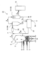
- FIG. 1 is a schematic configuration diagram showing a gasifier according to an embodiment of the present invention.
- the gasification apparatus 1 includes a gasification furnace 2 that gasifies a gasification raw material 3 to generate a generated gas G, and carbon such as char and tar components contained in the generated gas G generated in the gasification furnace 2. And a cleaning device 10 for removing the compound.
- the gasification furnace 2 in FIG. 1 is an example of a bubbling type fluidized bed gasification furnace.
- the gasification furnace 2 is configured to form a fluidized bed 9 with a fluidized medium 4, fluidize the fluidized bed 9 by blowing an oxidizer 5, and feed the gasified raw material 3 into the fluidized bed 9 for gasification. Has been.
- the oxidizing agent 5 is also blown into the free board portion 8 above the fluidized bed 9 to gasify unreacted volatile components.
- the residue 19 comprising the gasified raw material 3 and the fluidized medium 4 after the reaction is discharged from the lower side of the gasification furnace 2 to the outside of the gasification furnace.
- the product gas G generated in the gasification furnace 2 is discharged from the outlet 6 of the gasification furnace 2 and is sent to the cleaning device 10 through the communication path 7.
- the gasification temperature of the gasification raw material 3 in the gasification furnace 2 of the bubbling type fluidized bed is 600 ° C. to 800 ° C.
- a cleaning device 10 provided at a downstream position of the gasification furnace 2 includes a cyclone 11 for removing solid carbon compounds Cs such as char and ash, and a wet cleaning device 12 for removing volatile carbon compounds Cv such as tar components. And is composed of.
- the solid carbon compound Cs recovered from the product gas G by the cyclone 11 of the cleaning device 10 and the volatile carbon compound Cv recovered from the product gas G by the wet cleaning device 12 are a combustion device 13 to be described next. Introduced into.
- the solid carbon compound Cs and the volatile carbon compound Cv may be collectively referred to as a carbon compound.
- the combustion device 13 burns the carbon compound removed from the product gas G to produce a combustion gas CG containing carbon dioxide.
- the combustion device 13 includes an oxygen supply means 14 for sending oxygen 17 into the combustion device 13, and combustion in an oxygen concentration state higher than the oxygen concentration in the air, that is, in an oxygen-enriched state. It is configured to be able to do.
- the combustion gas CG generated in the combustion device 13 is a product gas G that is upstream of the cleaning device 10 and that enters the product gas G in a temperature region lower than the temperature of the combustion gas CG.
- a gas supply means 15 is provided.
- the combustion gas CG is supplied to the product gas G in the communication path 7 between the gasification furnace 2 and the cleaning device 10.
- An oxidant 5 is supplied to the fluid medium 4 in the gasification furnace 2 to form a fluidized fluidized bed 9.
- the gasification raw material 3 and the fluid medium 4 are supplied by a screw conveyor or the like.
- Examples of the gasification raw material 3 include organic waste such as plastic and rubber, biomass, and the like.
- the types of biomass include sawmill residue, thinned wood (cedar, firewood, pine, beech, rubber, etc.), roadside tree pruning material, building waste, waste power pole, bark, dam driftwood, rice husk, rice straw, straw , bamboo biomass, bamboo palm, palm palm empty fruit bunches, palm palm trunk, herbaceous biomass such as sugarcane derived from sugarcane, woody biomass such as cedar wood, pine wood, lauan wood, fig wood, cow dung, chicken manure, etc. Examples include livestock-derived biomass, food residues, black liquor, and seaweed.
- the generated gas G generated in the gasification step is sent to the cleaning device 10 on the downstream side of the gasification furnace 2, and a cleaning step for removing carbon compounds contained in the generated gas G is performed.
- the cleaning step the step of removing the volatile carbon compound Cv such as the tar component is performed using the wet cleaning device 12 or the like following the step of removing the solid carbon compound Cs such as char or ash using the cyclone 11 or the like.
- the solid carbon compound Cs recovered from the product gas G by the cyclone 11 and the volatile carbon compound Cv recovered from the product gas G by the wet cleaning device 12 are respectively introduced into the combustion device 13.
- the volatile carbon compound Cv is recovered in water in a wet cleaning device, and the volatile carbon compound Cv separated from the water is sent to the combustion device 13.
- the separated water 18 is reused or discarded.
- the product gas G cleaned by the cyclone 11 and the wet cleaning apparatus 12 is sent to another apparatus 16 on the downstream side.
- the carbon compound (solid carbon compound Cs and volatile carbon compound Cv) introduced into the combustion device 13 is burned to generate a high-temperature combustion gas CG containing carbon dioxide.
- the combustion device 13 since the combustion device 13 includes the oxygen supply means 14, oxygen 17 can be sent from the oxygen supply means 14 into the combustion device 13 and the carbon compound can be burned in an oxygen-enriched state. .
- oxygen 17 By burning the carbon compound in an oxygen-enriched state, a higher-temperature combustion gas CG can be generated.
- the oxygen 17 fed from the oxygen supply means 14 is pure oxygen.
- the combustion gas CG generated in the combustion device 13 is put into the generated gas G in the communication path 7 by the combustion gas supply means 15.
- the combustion temperature in the combustion device 13 is set so as to generate combustion gas CG having a temperature higher than the temperature of the product gas G upstream of the cleaning device 10.
- the combustion temperature of the combustion device 13 is set so that the combustion gas CG having a temperature higher than that of the product gas G in the communication passage 7 is generated.
- the product gas G contains carbon monoxide, carbon dioxide, hydrogen, and water vapor, and a so-called shift reaction occurs as shown in the formula (1).
- This reaction is an equilibrium reaction, and it is known that when the temperature of the reaction system is higher than the temperature in the equilibrium state, a so-called reverse shift reaction proceeds, that is, the reaction proceeds to the left.
- the combustion gas CG when the combustion gas CG is put into the product gas G upstream of the cleaning device 10 and in a temperature region lower than the temperature of the combustion gas CG, carbon dioxide ( CO 2) and the generation of hydrogen contained in the gas (H 2) and reacts, it is possible to proceed the reverse shift reaction to produce carbon monoxide and (CO) water vapor (H 2 O).
- the carbon compound contained in the product gas G can be reused to increase the gasification efficiency (yield) of the gasified raw material 3, and the amount of carbon monoxide contained in the product gas G Can be increased.
- the position where the combustion gas supply means 15 for putting the combustion gas CG into the product gas G is provided so as to put the combustion gas CG in a region downstream from the outlet 6 of the gasification furnace 2 as shown in FIG. It is desirable.
- the shift reaction and reverse shift reaction are reversible reactions, and a certain residence time is required to reach an equilibrium state at the temperature of the reaction system.
- the combustion gas CG is placed in a region downstream from the outlet 6 of the gasification furnace 2, that is, a flow path to the cleaning device 10, thereby securing a residence time for causing the reverse shift reaction to proceed.
- a product gas having a large amount of carbon monoxide, which is a product of the reverse shift reaction, can be sent to the cleaning device 10.
- silica sand containing SiO 2 or the like is used as the fluidized medium 4, but K (potassium), Na (sodium) are contained in the gasification raw material 3.
- the SiO 2 in the fluidized medium 4 may react with the alkali metal component in the gasified raw material 3 to form a compound having a melting point of about 700 ° C.
- a compound [potassium glass (K 2 O.3SiO 2 )] formed by a reaction between SiO 2 and a potassium compound has a melting point of about 750 ° C.
- a compound [soda glass (Na 2 O.3SiO 2 )] formed by a reaction between SiO 2 and a sodium-based compound has a melting point of about 635 ° C.
- the low-melting-point compound melted in the gasification furnace 2 causes the fluidizing medium 4 to adhere to cause a granulation phenomenon in which the particles of the fluidizing medium 4 become large. For this reason, when the temperature of the fluidized bed 9 becomes higher than the melting point, there is a problem that fluidization of the fluidized bed 9 is hindered by the granulation phenomenon of the fluidized medium, and gasification efficiency is deteriorated. In such a case, it is preferable to gasify the gasified raw material 3 by setting the temperature of the fluidized bed 9 to 740 ° C. or lower.
- the temperature of the fluidized bed is set low, the gasification efficiency decreases, so it is desirable to set the temperature to 740 ° C. or lower, for example, about 700 ° C. (about 650 ° C. to 730 ° C.). Since the melting point of the low melting point compound (soda glass) formed by the reaction of the sodium compound and SiO 2 is about 635 ° C., the sodium based low melting point compound is melted when set at around 700 ° C. Resulting in. However, when the amount of sodium compound contained in the gasification raw material is small and the influence of the granulation phenomenon due to the formation of the sodium low melting point compound is small, the temperature of the fluidized bed is set low. It is desirable to give priority to the problem of reduction in gasification efficiency due to this, and to suppress melting of the potassium-based low melting point compound (potassium glass) at a set temperature of around 700 ° C.
- the regasification reaction for generating the product gas G from the carbon compound does not proceed in the gasification furnace 2. There is a risk of temperature distribution in the furnace.
- the temperature in the gasification furnace 2 is set to a furnace temperature at which the regasification reaction performed by returning the carbon compound to the gasification furnace 2 does not proceed.
- the carbon compound can be reused to increase the gasification efficiency in the gasification furnace 2. Furthermore, the amount of carbon monoxide contained in the product gas G can be increased.
- the temperature distribution in the furnace where the regasification reaction does not proceed is such that the temperature in the gasification furnace 2 is partially high, and the temperature of the high temperature portion is a temperature at which the regasification reaction can occur.
- the gasification furnace 2 as a whole includes a furnace temperature distribution under a condition in which the regasification reaction does not proceed.
- the reverse shift is performed even when a gasification furnace that is operated at an in-furnace temperature distribution in which a regasification reaction of the carbon compound is performed by returning the carbon compound as it is to the gasification furnace.
- This is advantageous in that the amount of carbon monoxide in the product gas G can be increased by the reaction.
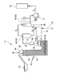
- FIG. 2 is a schematic configuration diagram showing a gasifier according to another embodiment of the present invention.
- the combustion gas supply means 25 of the gasifier 21 is configured to put the combustion gas CG generated in the combustion device 13 into the free board portion 8 of the gasifier 2.
- the combustion gas CG Can be placed in the free board portion 8 of the gasification furnace 2.
- the position where the combustion gas supply means 15 is provided it is preferable to set the position where the combustion gas supply means 15 is provided.
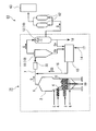
- FIG. 3 is a schematic configuration diagram showing a gasifier 31 according to still another embodiment of the present invention. Since the structures of the gasification furnace 2, the cleaning apparatus 10, the combustion apparatus 13, and the combustion gas supply means 15 of the gasification apparatus 31 of FIG. 3 are the same as those in the first embodiment, the same members are denoted by the same reference numerals, Detailed description thereof is omitted.
- the gasifier 31 of the present embodiment includes a cooling unit 32 that cools the generated gas G containing the combustion gas CG on the downstream side of the combustion gas supply unit 15.
- the cleaning device 10 removes and collects carbon compounds contained in the product gas G, and the carbon compounds are burned in an oxygen-enriched state in the combustion device 13 to burn carbon dioxide.
- Gas CG is generated.
- the combustion gas CG is put into the product gas G upstream of the cleaning device 10 by the combustion gas supply means 15 and in a temperature region lower than the temperature of the combustion gas CG.
- carbon dioxide (CO 2 ) in the combustion gas CG reacts with hydrogen (H 2 ) contained in the product gas G to generate carbon monoxide (CO) and water vapor (H 2 O).
- the reverse shift reaction can proceed.
- the gasifier 31 of the present embodiment includes the cooling means 32, the combustion gas CG is put into the product gas G, and the product gas G after the reverse shift reaction proceeds, It can be cooled by the cooling means 32 and lowered to a gas temperature at which the shift reaction does not occur, and a state in which the amount of carbon monoxide in the product gas G is large can be maintained.
- the temperature of the product gas G cooled by the cooling means 32 is desirably a temperature at which volatile components (tar and the like) remaining in the product gas G are deposited and do not adhere to the gasification furnace 2. . Further, the cooling means 32 is set at a position where a sufficient residence time can be secured for allowing the reverse shift reaction to proceed after the combustion gas CG is put into the product gas G by the combustion gas supply means 15. Is desirable.
- the gasification furnace used in the present embodiment is not limited to this, and other fluidized bed gasification furnaces such as a circulation type, and gasification furnaces such as a fixed bed type, a spouted bed type, and a rotary kiln type are also used. be able to.
- a circulation type such as a circulation type
- gasification furnaces such as a fixed bed type, a spouted bed type, and a rotary kiln type are also used. be able to.
- Example 4 the case where a down draft type fixed bed type gasification furnace is used as the gasification furnace 2 will be described.
- Example 4 In the gasifier 41 shown in FIG. 4, a downdraft fixed bed gasifier is used as the gasifier 42.
- the gasification furnace 42 is supplied with a gasification raw material 43 from an opening 44 at the top of the gasification furnace 42, takes air as an oxidant 45 from the opening 44, and incompletely burns the gasification raw material 43. Gasified to produce product gas G.
- the gasification furnace 42 is provided with an oxidant intake port 60 communicating with the atmosphere outside the gasification furnace 42 on the downstream side of the opening 44, and the gasification reaction efficiency of the gasification raw material 43 is increased. In order to raise, it is comprised so that the air outside the gasification furnace 42 may be taken in.
- the residue 59 of the gasified raw material 43 after the reaction is discharged from the lower part of the gasification furnace 42 to the outside of the furnace.
- the product gas G generated in the gasification furnace 42 is discharged from an outlet 46 of the gasification furnace 42, and a cyclone 48 for removing the solid carbon compound Cs such as char and ash from the communication passage 47, and tar. It is sent to a cleaning device 50 comprising a wet cleaning device 49 for removing volatile carbon compounds Cv such as components.
- the solid carbon compound Cs recovered by the cyclone 48 and the volatile carbon compound Cv recovered by the wet cleaning device 49 are configured to be introduced into a combustion device 53 described later. Since the volatile carbon compound Cv is recovered in water in the wet cleaning device 49, the volatile carbon compound Cv and the water 58 are separated, and the separated volatile carbon compound Cv is supplied to the combustion device 53. be introduced.
- an attracting air blowing means 51 such as an attracting air fan is provided to take in air as the oxidizing agent 45 from the opening 44 and the oxidizing agent inlet 60,
- the generated product gas G is discharged from the outlet 46 of the gasification furnace 42 and sent to the cleaning device 50.
- the generated gas G cleaned in the cleaning device 50 is sent to another device 52 by the blowing force of the attraction blowing means 51.
- the combustion apparatus 53 including the oxygen supply means 54 for sending oxygen 57 and the combustion gas supply means 55 are provided.
- the cooling means 56 it is possible to generate the product gas G by reusing the carbon compounds such as char and tar components removed and recovered from the product gas G, and carbon monoxide in the product gas G. The amount can be increased.
- FIG. 5 is a schematic configuration diagram showing an ethanol production facility 61 for producing ethanol as a liquid fuel.
- the ethanol production facility 61 of Example 5 includes a gasifier 31 as a gasifier that generates a product gas G from a gasification raw material. Since the gasifier 31 has the same configuration as that of the gasifier of the third embodiment, the same members are denoted by the same reference numerals, and detailed description thereof is omitted.
- the downstream side of the gasifier 31 is provided with an ethanol production device 63 for producing ethanol from the generated gas G using anaerobic microorganisms.
- another apparatus may be interposed between the cleaning apparatus 10 (wet cleaning apparatus 12) of the gasifier 31 and the ethanol production apparatus 33.
- a purification device 62 for purifying the generated gas G cleaned by the cleaning device 10 of the gasifier 31 is provided.
- the purification device 62 is, for example, a filter intended to remove fine particles, tar, and the like that could not be removed by the cleaning device 10, and is configured to use two filters by switching in this embodiment. Yes.
- the product gas G containing a large amount of carbon monoxide can be generated in the gasifier 31, and the product gas G can be supplied to the ethanol production device 63. Since anaerobic microorganisms use carbon monoxide to produce ethanol, supplying the product gas G containing a large amount of carbon monoxide to the ethanol production apparatus 63 increases the ability of ethanol production by the anaerobic microorganisms, and efficiently. Ethanol can be produced.
- the gasifier used for a present Example is not limited to the said Example, It cannot be overemphasized that the gasifier of the aspect which concerns on this invention can be used.
- a present Example is ethanol production equipment which manufactures ethanol using the said ethanol manufacturing apparatus 33, by using the manufacturing apparatus which manufactures alcohol, such as methanol, propanol, butanol, using carbon monoxide as a raw material, Various alcohols can be produced.
- the present invention can be used in a gasification apparatus and a gasification method for gasifying a gasification raw material into a product gas such as carbon monoxide, carbon dioxide, hydrogen, and water vapor. Moreover, it can utilize for the liquid fuel manufacturing facility which manufactures alcohol from the said production
Landscapes
- Chemical & Material Sciences (AREA)
- Engineering & Computer Science (AREA)
- Combustion & Propulsion (AREA)
- Oil, Petroleum & Natural Gas (AREA)
- Organic Chemistry (AREA)
- Industrial Gases (AREA)
- Organic Low-Molecular-Weight Compounds And Preparation Thereof (AREA)
- Liquid Carbonaceous Fuels (AREA)
- Processing Of Solid Wastes (AREA)
Abstract
Description
CO + H2O ⇔ CO2 + H2 ・・・ (1)
この反応は平衡反応であり、反応系の温度を平衡状態の温度より高くすると、反応が左に進む、いわゆる逆シフト反応が進行することが知られている。
このことによって、前記炭素化合物を再利用して生成ガスを生成し、被ガス化原料のガス化効率(収率)を高めることができるとともに、生成ガス中に含まれる一酸化炭素量を増加させることができる。
本態様によれば、第1の態様または第2の態様と同様の作用効果に加え、前記燃焼装置において、前記炭素化合物を酸素富化状態で燃焼させることができるので、より高温の燃焼ガスを生成することが可能となり、前記ガス化炉で生成した生成ガスよりも高い温度の燃焼ガスを確実に生成させることができる。
尚、冷却手段によって冷却された生成ガス温度は、該生成ガス中のタール成分が析出してガス化炉内に付着しない程度の温度(約500℃)であることが望ましい。
本態様によれば、前記燃焼ガスを、前記ガス化炉の出口より下流の領域、すなわち、洗浄装置に至るまでの流路に入れることによって、前記逆シフト反応を進行させるための滞留時間を確保し、逆シフト反応の生成物である一酸化炭素が多い状態の生成ガスを洗浄装置に送ることができる。
本発明に係るガス化装置の一実施形態を図1に基づいて説明する。図1は、本発明の一実施形態に係るガス化装置を示す概略構成図である。
ガス化装置1は、被ガス化原料3をガス化して生成ガスGを生成するガス化炉2と、該ガス化炉2において生成した前記生成ガスG中に含まれるチャーやタール成分等の炭素化合物を除去する洗浄装置10とを備えている。
前記ガス化炉2内の流動媒体4に酸化剤5を供給して流動状態の流動床9を形成する。前記ガス化炉2に設けられた昇温バーナー(図示せず)によって、前記流動床の温度を設定温度まで高め、その流動床9に被ガス化原料3を供給してガス化するガス化工程が行われる。前記被ガス化原料3、および流動媒体4は、スクリューコンベア等によって供給される。
CO + H2O ⇔ CO2 + H2 ・・・ (1)
この反応は平衡反応であり、反応系の温度を平衡状態の温度より高くすると、反応が左に進む、いわゆる逆シフト反応が進行することが知られている。
このことによって、生成ガスG中に含まれる炭素化合物を再利用して、被ガス化原料3のガス化効率(収率)を高めることができるとともに、生成ガスG中に含まれる一酸化炭素量を増加させることができる。
また、流動床の温度を低く設定するとガス化効率が低下するため、740℃以下の例えば700℃程度(650℃~730℃程度)に設定することが望ましい。なお、前記ナトリウム系化合物とSiO2の反応により形成された低融点化合物(ソーダガラス)の融点は約635℃であるので、700℃前後に設定した場合には該ナトリウム系の低融点化合物は融解してしまう。しかし、被ガス化原料中に含まれるナトリウム系化合物の量が少なく、前記ナトリウム系の低融点化合物が形成されることによる前記造粒現象の影響が少ない場合には、流動床の温度を低く設定することによるガス化効率の低下の問題を優先し、700℃前後の設定温度によってカリウム系の低融点化合物(カリガラス)の融解を抑えるようにすることが望ましい。
次に、本発明に係るガス化装置の他の実施形態を図2に基づいて説明する。図2は、本発明の他の実施形態に係るガス化装置を示す概略構成図である。
次に、本発明に係るガス化装置の更に他の実施形態を図3に基づいて説明する。図3は、本発明の更に他の実施形態に係るガス化装置31を示す概略構成図である。
図3のガス化装置31のガス化炉2、洗浄装置10、燃焼装置13、およびの燃焼ガス供給手段15の構成は実施例1と同じであるので、同一部材には同一符号を付し、その詳細な説明は省略する。本実施例のガス化装置31は、前記燃焼ガス供給手段15よりも下流側に、前記燃焼ガスCGを入れた生成ガスGを冷却する冷却手段32を備えている。
図4に示すガス化装置41では、ガス化炉42としてダウンドラフト型固定床式ガス化炉を用いている。
ガス化炉42は、ガス化炉42上部の開口部44から被ガス化原料43が供給され、前記開口部44から酸化剤45として空気を取り込んで、前記被ガス化原料43を不完全燃焼させてガス化させ、生成ガスGを生成する。また、ガス化炉42は、前記開口部44よりも下流側に、該ガス化炉42外の大気と連通する酸化剤取入口60を備えており、被ガス化原料43のガス化反応効率を高めるため、ガス化炉42外の空気を取り込むように構成されている。反応後の被ガス化原料43の残渣59は、ガス化炉42の下部から炉外へ排出される。
次に、本発明に係る液体燃料製造設備の一実施形態を図5に基づいて説明する。図5は、液体燃料としてエタノールを製造するエタノール製造設備61を示す概略構成図である。
実施例5のエタノール製造設備61は、被ガス化原料から生成ガスGを生成するガス化装置としてガス化装置31を備えている。ガス化装置31は実施例3のガス化装置と同様の構成であるので、同一部材には同一符号を付し、その詳細な説明は省略する。
尚、本実施例に用いるガス化装置は、上記実施例に限定されるものではなく、本発明に係るいずれかの態様のガス化装置を用いることができるのは言うまでもない。また、本実施例は、前記エタノール製造装置33を用いてエタノールを製造するエタノール製造設備であるが、一酸化炭素を原料としてメタノール、プロパノール、ブタノール等のアルコールを製造する製造装置を用いることによって、各種アルコールを製造することができる。
Claims (8)
- 被ガス化原料をガス化して生成ガスを生成するガス化炉と、
前記生成ガス中に含まれる炭素化合物を除去する洗浄装置と、
前記炭素化合物を燃焼させて二酸化炭素を含む燃焼ガスを生成する燃焼装置と、を備え、
前記燃焼ガスを、前記洗浄装置より上流側の生成ガスであって、該燃焼ガスの温度より低い温度領域の生成ガス中に入れるように構成されたガス化装置。 - 請求項1に記載されたガス化装置において、前記ガス化炉は、該ガス化炉内で前記炭素化合物から生成ガスを生成する再ガス化反応が進行しない炉内温度分布であることを特徴とするガス化装置。
- 請求項1または請求項2に記載されたガス化装置において、前記燃焼装置は、酸素富化状態で燃焼させるように構成されていることを特徴とするガス化装置。
- 請求項1から請求項3のいずれか一項に記載されたガス化装置において、前記燃焼ガスを入れた生成ガスを冷却する冷却手段を備えたことを特徴とするガス化装置。
- 請求項1から請求項4のいずれか一項に記載されたガス化装置において、前記燃焼ガスを、前記ガス化炉の出口より下流の領域に入れるように構成されていることを特徴とするガス化装置。
- 請求項1から請求項5のいずれか一項に記載されたガス化装置において、前記ガス化炉は、前記被ガス化原料をガス化する流動床を備え、前記流動床の温度は740℃以下に設定されていることを特徴とするガス化装置。
- ガス化炉において被ガス化原料をガス化し、生成ガスを生成するガス化工程と、
前記生成ガス中に含まれる炭素化合物を除去する洗浄工程と、を含み、
前記炭素化合物を燃焼させて二酸化炭素を含む燃焼ガスを生成させ、該燃焼ガスを、前記洗浄装置より上流側の生成ガスであって、該燃焼ガスの温度より低い温度領域の生成ガス中に入れることを特徴とするガス化方法。 - 請求項1から請求項6のいずれか一項に記載されたガス化装置と、
前記ガス化装置で生成された生成ガスを原料としてアルコールを製造するアルコール製造装置と、を備えた液体燃料製造設備。
Priority Applications (1)
| Application Number | Priority Date | Filing Date | Title |
|---|---|---|---|
| CN201080014089.7A CN102405273B (zh) | 2009-03-31 | 2010-03-26 | 气化装置、气化方法及液体燃料制造设备 |
Applications Claiming Priority (2)
| Application Number | Priority Date | Filing Date | Title |
|---|---|---|---|
| JP2009-088242 | 2009-03-31 | ||
| JP2009088242A JP5153711B2 (ja) | 2009-03-31 | 2009-03-31 | ガス化装置、ガス化方法、および液体燃料製造設備 |
Publications (1)
| Publication Number | Publication Date |
|---|---|
| WO2010113802A1 true WO2010113802A1 (ja) | 2010-10-07 |
Family
ID=42828093
Family Applications (1)
| Application Number | Title | Priority Date | Filing Date |
|---|---|---|---|
| PCT/JP2010/055382 Ceased WO2010113802A1 (ja) | 2009-03-31 | 2010-03-26 | ガス化装置、ガス化方法、および液体燃料製造設備 |
Country Status (3)
| Country | Link |
|---|---|
| JP (1) | JP5153711B2 (ja) |
| CN (1) | CN102405273B (ja) |
| WO (1) | WO2010113802A1 (ja) |
Cited By (4)
| Publication number | Priority date | Publication date | Assignee | Title |
|---|---|---|---|---|
| JP2013542291A (ja) * | 2010-10-29 | 2013-11-21 | エネルケム,インコーポレイテッド | 残留生成物の酸化により得られる熱ガスを用いて加熱することによる酸化されたバイオマスからの合成ガスの生成 |
| JP2015077120A (ja) * | 2013-09-13 | 2015-04-23 | 積水化学工業株式会社 | 有機物質の製造方法及び有機物質の製造装置 |
| EP3272873A4 (en) * | 2015-03-20 | 2018-10-17 | Sekisui Chemical Co., Ltd. | Method and device for producing organic substance |
| WO2021132046A1 (ja) * | 2019-12-27 | 2021-07-01 | 日立造船株式会社 | ガス化システム |
Citations (2)
| Publication number | Priority date | Publication date | Assignee | Title |
|---|---|---|---|---|
| JP2000087045A (ja) * | 1998-09-11 | 2000-03-28 | Nippon Steel Corp | 石炭熱分解法における石炭前処理方法 |
| JP2002193858A (ja) * | 2000-12-28 | 2002-07-10 | Mitsubishi Heavy Ind Ltd | バイオマス原料によるメタノール製造方法及びその装置 |
Family Cites Families (1)
| Publication number | Priority date | Publication date | Assignee | Title |
|---|---|---|---|---|
| JP4259777B2 (ja) * | 2001-07-31 | 2009-04-30 | 井上 斉 | バイオマスのガス化方法 |
-
2009
- 2009-03-31 JP JP2009088242A patent/JP5153711B2/ja not_active Expired - Fee Related
-
2010
- 2010-03-26 CN CN201080014089.7A patent/CN102405273B/zh not_active Expired - Fee Related
- 2010-03-26 WO PCT/JP2010/055382 patent/WO2010113802A1/ja not_active Ceased
Patent Citations (2)
| Publication number | Priority date | Publication date | Assignee | Title |
|---|---|---|---|---|
| JP2000087045A (ja) * | 1998-09-11 | 2000-03-28 | Nippon Steel Corp | 石炭熱分解法における石炭前処理方法 |
| JP2002193858A (ja) * | 2000-12-28 | 2002-07-10 | Mitsubishi Heavy Ind Ltd | バイオマス原料によるメタノール製造方法及びその装置 |
Cited By (4)
| Publication number | Priority date | Publication date | Assignee | Title |
|---|---|---|---|---|
| JP2013542291A (ja) * | 2010-10-29 | 2013-11-21 | エネルケム,インコーポレイテッド | 残留生成物の酸化により得られる熱ガスを用いて加熱することによる酸化されたバイオマスからの合成ガスの生成 |
| JP2015077120A (ja) * | 2013-09-13 | 2015-04-23 | 積水化学工業株式会社 | 有機物質の製造方法及び有機物質の製造装置 |
| EP3272873A4 (en) * | 2015-03-20 | 2018-10-17 | Sekisui Chemical Co., Ltd. | Method and device for producing organic substance |
| WO2021132046A1 (ja) * | 2019-12-27 | 2021-07-01 | 日立造船株式会社 | ガス化システム |
Also Published As
| Publication number | Publication date |
|---|---|
| JP2010235899A (ja) | 2010-10-21 |
| CN102405273A (zh) | 2012-04-04 |
| CN102405273B (zh) | 2014-04-02 |
| JP5153711B2 (ja) | 2013-02-27 |
Similar Documents
| Publication | Publication Date | Title |
|---|---|---|
| CN103154209B (zh) | 用于转化燃料的装置 | |
| KR100641760B1 (ko) | 가연성 합성 기체 제조 방법 및 제조 장치 | |
| US20180305627A1 (en) | Industrial furnace integrated with biomass gasification system | |
| WO2012161203A1 (ja) | 廃棄物溶融処理方法 | |
| ES2397447B1 (es) | Dispositivo reactor dual de gasificación-pirólisis. | |
| JP5153711B2 (ja) | ガス化装置、ガス化方法、および液体燃料製造設備 | |
| US20130047573A1 (en) | Heat recovery systems for biomass gasification systems | |
| ES2992347T3 (es) | Proceso para gasificar una materia orgánica y planta para llevar a cabo dicho proceso | |
| JP2010223564A (ja) | 流動床式ガス化炉の運転方法及び流動床式ガス化炉 | |
| SK10472000A3 (sk) | Spôsob spracovania tuhých palivových materiálov a zariadenie na vykonávanie tohto spôsobu | |
| US20140102002A1 (en) | Gasification of bio-oil and alkali containing energy rich aqueous solutions from pulp mills | |
| EP2782984B1 (fr) | Procede de production de biomethane | |
| JP2006124496A (ja) | 石炭およびバイオマスの共熱分解装置および方法 | |
| JP2010222544A (ja) | 流動床式ガス化炉の運転方法及び流動床式ガス化炉 | |
| JP4509162B2 (ja) | バイオマスのガス化装置 | |
| JP2005075925A (ja) | 有機質廃材熱分解炭化法 | |
| JP2010270264A (ja) | 循環流動層式ガス化方法及び装置 | |
| JP3009536B2 (ja) | 有機物を主体とする廃棄物のガス化方法 | |
| FI123354B (fi) | Järjestely ja menetelmä kiinteän polttoaineen kaasuttamiseksi | |
| JP4981202B2 (ja) | バイオマスガス化炉 | |
| JP2014125578A (ja) | 生成ガスの製造方法、製造装置及び高温燃焼ガス発生装置 | |
| JP5945929B2 (ja) | 廃棄物ガス化溶融装置 | |
| KR101197720B1 (ko) | 기동/정지과정 중 우드칩 가스화기에서 생산된 타르합성가스 처리장치 및 처리방법 | |
| JP2011106795A (ja) | 流動床式ガス化炉、流動床式ガス化システム、アグロメーション物質分離方法 | |
| JP2009240888A (ja) | 廃棄物ガス化処理システム |
Legal Events
| Date | Code | Title | Description |
|---|---|---|---|
| WWE | Wipo information: entry into national phase |
Ref document number: 201080014089.7 Country of ref document: CN |
|
| 121 | Ep: the epo has been informed by wipo that ep was designated in this application |
Ref document number: 10758574 Country of ref document: EP Kind code of ref document: A1 |
|
| WWE | Wipo information: entry into national phase |
Ref document number: 2014/MUMNP/2011 Country of ref document: IN |
|
| NENP | Non-entry into the national phase |
Ref country code: DE |
|
| 122 | Ep: pct application non-entry in european phase |
Ref document number: 10758574 Country of ref document: EP Kind code of ref document: A1 |