WO2010113643A1 - 露光方法及び露光装置 - Google Patents
露光方法及び露光装置 Download PDFInfo
- Publication number
- WO2010113643A1 WO2010113643A1 PCT/JP2010/054564 JP2010054564W WO2010113643A1 WO 2010113643 A1 WO2010113643 A1 WO 2010113643A1 JP 2010054564 W JP2010054564 W JP 2010054564W WO 2010113643 A1 WO2010113643 A1 WO 2010113643A1
- Authority
- WO
- WIPO (PCT)
- Prior art keywords
- exposure
- exposed
- mask pattern
- pattern group
- photomask
- Prior art date
- Legal status (The legal status is an assumption and is not a legal conclusion. Google has not performed a legal analysis and makes no representation as to the accuracy of the status listed.)
- Ceased
Links
Images




Classifications
-
- G—PHYSICS
- G03—PHOTOGRAPHY; CINEMATOGRAPHY; ANALOGOUS TECHNIQUES USING WAVES OTHER THAN OPTICAL WAVES; ELECTROGRAPHY; HOLOGRAPHY
- G03F—PHOTOMECHANICAL PRODUCTION OF TEXTURED OR PATTERNED SURFACES, e.g. FOR PRINTING, FOR PROCESSING OF SEMICONDUCTOR DEVICES; MATERIALS THEREFOR; ORIGINALS THEREFOR; APPARATUS SPECIALLY ADAPTED THEREFOR
- G03F7/00—Photomechanical, e.g. photolithographic, production of textured or patterned surfaces, e.g. printing surfaces; Materials therefor, e.g. comprising photoresists; Apparatus specially adapted therefor
- G03F7/70—Microphotolithographic exposure; Apparatus therefor
- G03F7/70691—Handling of masks or workpieces
- G03F7/70791—Large workpieces, e.g. glass substrates for flat panel displays or solar panels
-
- G—PHYSICS
- G03—PHOTOGRAPHY; CINEMATOGRAPHY; ANALOGOUS TECHNIQUES USING WAVES OTHER THAN OPTICAL WAVES; ELECTROGRAPHY; HOLOGRAPHY
- G03F—PHOTOMECHANICAL PRODUCTION OF TEXTURED OR PATTERNED SURFACES, e.g. FOR PRINTING, FOR PROCESSING OF SEMICONDUCTOR DEVICES; MATERIALS THEREFOR; ORIGINALS THEREFOR; APPARATUS SPECIALLY ADAPTED THEREFOR
- G03F7/00—Photomechanical, e.g. photolithographic, production of textured or patterned surfaces, e.g. printing surfaces; Materials therefor, e.g. comprising photoresists; Apparatus specially adapted therefor
- G03F7/70—Microphotolithographic exposure; Apparatus therefor
- G03F7/70691—Handling of masks or workpieces
- G03F7/70733—Handling masks and workpieces, e.g. exchange of workpiece or mask, transport of workpiece or mask
-
- G—PHYSICS
- G03—PHOTOGRAPHY; CINEMATOGRAPHY; ANALOGOUS TECHNIQUES USING WAVES OTHER THAN OPTICAL WAVES; ELECTROGRAPHY; HOLOGRAPHY
- G03F—PHOTOMECHANICAL PRODUCTION OF TEXTURED OR PATTERNED SURFACES, e.g. FOR PRINTING, FOR PROCESSING OF SEMICONDUCTOR DEVICES; MATERIALS THEREFOR; ORIGINALS THEREFOR; APPARATUS SPECIALLY ADAPTED THEREFOR
- G03F7/00—Photomechanical, e.g. photolithographic, production of textured or patterned surfaces, e.g. printing surfaces; Materials therefor, e.g. comprising photoresists; Apparatus specially adapted therefor
- G03F7/70—Microphotolithographic exposure; Apparatus therefor
- G03F7/70216—Mask projection systems
- G03F7/70283—Mask effects on the imaging process
-
- G—PHYSICS
- G03—PHOTOGRAPHY; CINEMATOGRAPHY; ANALOGOUS TECHNIQUES USING WAVES OTHER THAN OPTICAL WAVES; ELECTROGRAPHY; HOLOGRAPHY
- G03F—PHOTOMECHANICAL PRODUCTION OF TEXTURED OR PATTERNED SURFACES, e.g. FOR PRINTING, FOR PROCESSING OF SEMICONDUCTOR DEVICES; MATERIALS THEREFOR; ORIGINALS THEREFOR; APPARATUS SPECIALLY ADAPTED THEREFOR
- G03F7/00—Photomechanical, e.g. photolithographic, production of textured or patterned surfaces, e.g. printing surfaces; Materials therefor, e.g. comprising photoresists; Apparatus specially adapted therefor
- G03F7/70—Microphotolithographic exposure; Apparatus therefor
- G03F7/70216—Mask projection systems
- G03F7/70358—Scanning exposure, i.e. relative movement of patterned beam and workpiece during imaging
-
- G—PHYSICS
- G03—PHOTOGRAPHY; CINEMATOGRAPHY; ANALOGOUS TECHNIQUES USING WAVES OTHER THAN OPTICAL WAVES; ELECTROGRAPHY; HOLOGRAPHY
- G03F—PHOTOMECHANICAL PRODUCTION OF TEXTURED OR PATTERNED SURFACES, e.g. FOR PRINTING, FOR PROCESSING OF SEMICONDUCTOR DEVICES; MATERIALS THEREFOR; ORIGINALS THEREFOR; APPARATUS SPECIALLY ADAPTED THEREFOR
- G03F7/00—Photomechanical, e.g. photolithographic, production of textured or patterned surfaces, e.g. printing surfaces; Materials therefor, e.g. comprising photoresists; Apparatus specially adapted therefor
- G03F7/70—Microphotolithographic exposure; Apparatus therefor
- G03F7/70425—Imaging strategies, e.g. for increasing throughput or resolution, printing product fields larger than the image field or compensating lithography- or non-lithography errors, e.g. proximity correction, mix-and-match, stitching or double patterning
Definitions
- the present invention relates to an exposure method and an exposure apparatus that form different exposure patterns for a plurality of exposure areas set on an exposure object while conveying the exposure object in one direction.
- the present invention relates to an exposure method and an exposure apparatus for improving the formation efficiency.
- this type of exposure method selects one mask pattern group of a photomask while conveying the object to be exposed in one direction, and applies the one mask pattern group to a predetermined exposure region of the object to be exposed.
- An exposure pattern group is formed by exposure, and then the object to be exposed is returned to the standby position before the exposure is started. Then, the mask pattern group of the photomask is switched to another mask pattern group, and then the object to be exposed is conveyed. Then, another exposure pattern group is exposed and formed in another exposure region of the object to be exposed by the other mask pattern group (see, for example, Patent Document 1).
- an object of the present invention is to provide an exposure method and an exposure apparatus that address such problems and improve the formation efficiency of a plurality of types of exposure patterns on the same object to be exposed.
- the exposure method according to the present invention forms different exposure patterns for each of a plurality of exposure areas set at predetermined intervals in the transport direction of the exposed object while transporting the exposed object in one direction.
- the photomask When the exposure of one exposure region of the exposure body is completed, the photomask is moved in synchronization with the conveyance speed of the object to be exposed and switched from the one mask pattern group to another mask pattern group, and the photo When the switching of the mask from the one mask pattern group to another mask pattern group is completed, the movement of the photomask is stopped and the other mask pattern group is moved. A step of performing exposure of the next exposure area of the subject to be exposed, and performs.
- one mask pattern of a photomask formed by arranging a plurality of types of mask pattern groups corresponding to each exposure pattern at a predetermined interval in the conveyance direction of the exposure object while conveying the exposure object in one direction.
- the photomask is moved in synchronization with the conveyance speed of the object to be exposed and switched from one mask pattern group to another mask pattern group.
- the movement of the photomask is stopped, and the exposure to the next exposure area of the object to be exposed is performed by another mask pattern group,
- Different exposure patterns are formed for each of a plurality of exposure areas set at predetermined intervals in the conveyance direction of the object to be exposed.
- the photomask moves in the transport direction of the object to be exposed. Thereby, the photomask is moved in the conveying direction of the object to be exposed, and the mask pattern group is switched.
- An exposure apparatus is an exposure apparatus that forms a different exposure pattern for each of a plurality of exposure areas set at predetermined intervals in the transport direction of the object to be exposed while transporting the object to be exposed in one direction.
- a conveying unit that conveys the object to be exposed at a predetermined speed; and a plurality of types of mask pattern groups corresponding to the exposure patterns arranged in the conveying direction of the object to be exposed.
- the mask stage Holding a photomask formed side by side at a predetermined interval, and a mask stage formed so as to be movable in synchronization with the movement of the transfer means, and using one mask pattern group of the photomask,
- the mask stage is moved to switch from one mask pattern group of the photomask to another mask pattern group,
- the mask pattern group is to perform the exposure for the next exposure area of the object to be exposed.
- the mask stage is moved in synchronization with the movement of the object to be exposed to switch from one mask pattern group of the photomask to another mask pattern group, and the next exposure area of the object to be exposed is exposed by the other mask pattern group. This is executed to form different exposure patterns for each of a plurality of exposure areas set at predetermined intervals in the conveyance direction of the object to be exposed.
- the mask stage moves in the transport direction of the object to be exposed. Thereby, the photomask is moved in the conveying direction of the object to be exposed, and the mask pattern group is switched.
- the object to be exposed is continued without returning the object to the standby position before the start of exposure.
- FIG. 1 is a schematic view showing an embodiment of an exposure apparatus according to the present invention.
- This exposure apparatus forms a different exposure pattern for each of a plurality of exposure areas set on an object to be exposed while carrying the object to be exposed in one direction during the exposure process.
- a light source 2 a coupling optical system 3, a mask stage 4, an imaging means 6, and a control means 7.
- the transport means 1 places the object 8 to be exposed on the upper surface 1a and transports it at a predetermined speed in the direction indicated by the arrow A. Air is ejected from the upper surface 1a and sucked, and the air is ejected. In a state in which the object to be exposed 8 is floated by a predetermined amount while being balanced with suction, both end edges of the object to be exposed 8 are held and conveyed by a conveyance roller (not shown). Further, the transport unit 1 includes a speed sensor that detects the moving speed of the object to be exposed 8 and a position sensor (not shown) that detects the position of the object to be exposed 8.
- the object 8 to be used here includes a first exposure region 9 in which a first exposure pattern group is to be formed and a second exposure pattern group in which a second exposure pattern group is to be formed.
- the exposure area 10 is preset in the transport direction (arrow A direction) at an interval W, for example, a multi-colored color filter substrate.
- a light source 2 is provided above the conveying means 1.
- the light source 2 emits ultraviolet rays as the light source light 5, and is a xenon lamp, an ultrahigh pressure mercury lamp, a laser light source, or the like.
- a coupling optical system 3 is provided in front of the light source 2 in the light emission direction.
- the coupling optical system 3 converts the light source light 5 emitted from the light source 2 into parallel light and irradiates a mask pattern group of a photomask 11 described later, and includes optical components such as a photo integrator and a condenser lens. It is configured. Further, a mask for shaping the cross-sectional shape of the light source light 5 in accordance with the outer shape of the formation region of each mask pattern group of the photomask 11 is also provided.
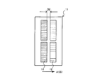
- a mask stage 4 is provided opposite to the upper surface of the transfer means 1. As shown in FIG. 3, the mask stage 4 includes first and second mask pattern groups 12 and 13 respectively corresponding to different types of first and second exposure pattern groups formed on the object 8 to be exposed. Further, the photomask 11 formed side by side in the transport direction (arrow A direction) of the exposure object 8 at the same interval W as the interval between the first and second exposure regions 9 and 10 set on the exposure object 8. The peripheral edge portion is held, and is configured to be movable in the same direction as the conveyance direction of the object to be exposed 8 indicated by arrow A (in the direction of arrow B) in synchronization with the moving speed of the object to be exposed 8.
- the imaging means 6 is provided so as to be able to image a position away from the exposure position by the photomask 11 by a predetermined distance in the direction opposite to the transport direction (arrow A direction).
- the imaging means 6 images the surface of the object to be exposed 8 and is a line in which a plurality of light receiving elements are arranged in a straight line in a direction substantially perpendicular to the transport direction in a plane parallel to the upper surface of the transport means 1. It is a camera.
- the image pickup means 6 is arranged so as to pick up an image of a position separated by a distance L in the direction opposite to the transport direction with reference to the exposure center position of the mask pattern group of the photomask 11.
- Control means 7 is provided in electrical connection with the conveying means 1, light source 2, mask stage 4, and imaging means 6.
- the control means 7 appropriately controls the movement of the transport means 1 and the mask stage 4, and as shown in FIG. 4, the image processing section 14, the memory 15, the calculation section 16, and the comparator 17.
- the image processing unit 14 processes the image of the surface of the object to be exposed 8 picked up by the image pickup means 6 and detects the position of each exposure region 9, 10 on the leading side in the transport direction.
- the memory 15 stores the dimension of each exposure area 9, 10 in the direction of arrow A, the distance L between the exposure center position by the photomask 11 and the imaging position by the imaging means 6, and the arithmetic unit described later.
- the calculation result in 16 is temporarily stored.
- the calculation unit 16 calculates the moving distance of the object to be exposed 8 based on the output of the position sensor of the transport unit 1.
- the comparator 17 compares the moving distance of the conveying means 1 calculated by the calculating unit 16 with each dimension read from the memory 15.
- the transport unit drive controller 18 controls the drive of the transport unit 1 so that the object to be exposed 8 moves at a predetermined speed. Further, the mask stage drive controller 19 switches the mask stage 4 from the first mask pattern group 12 of the photomask 11 to the second mask pattern group 13 by moving the mask stage 4 in synchronization with the movement of the object 8 to be exposed. . Furthermore, the light source drive controller 20 controls the turning on and off of the light source 2. And the control part 21 integrates and controls the whole apparatus so that each said component may drive appropriately.
- step S1 the mask stage 4 stops at the standby position, and the first mask pattern group 12 of the photomask 11 is selected.
- step S2 the transport unit 1 is controlled and driven by the transport unit drive controller 18 to start the operation of transporting the object 8 to be exposed in the direction of arrow A at a predetermined speed.
- step S3 the image processing unit 14 processes the image of the surface of the object to be exposed 8 imaged by the imaging unit 6, and at the front edge of the first exposure region 9 in the arrow A direction, for example, the first The front edge of the reference pattern group composed of a plurality of reference patterns formed in advance in the exposure area 9 in the direction of arrow A is detected.
- step S ⁇ b> 4 the calculation unit 16 calculates the distance that the object 8 moves after detecting the front edge of the first exposure region 9 in the direction of arrow A based on the output of the position sensor of the transport unit 1. Then, the movement distance of the object to be exposed 8 calculated by the comparator 17 is compared with the distance L read from the memory 15. If they match and the determination is “YES” in step S4, the process proceeds to step S5.
- step S5 the light source drive controller 20 is activated to turn on the light source 2.
- the light source light 5 radiated from the light source 2 converted into parallel light through the coupling optical system 3, and further shaped in accordance with the outer shape of the mask pattern group is obtained from the light source light 5 of the photomask 11.
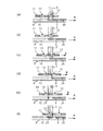
- the first exposure pattern 24 is exposed and formed in the first exposure region 9 of the object 8 to be exposed (see FIG. 6A).
- step S ⁇ b> 6 the movement distance of the object to be exposed 8 is calculated by the calculation unit 16 based on the output of the position sensor of the transport unit 1, and the distance and the first exposure area 9 read from the memory 15 in the direction of arrow A. The dimensions are compared by the comparator 17, and it is determined whether or not the two match and the exposure for the first exposure region 9 is completed. Here, if the two match (see FIG. 6B) and the determination is “YES” in step S6, the process proceeds to step S7.
- step S7 the mask stage drive controller 19 is activated to move the mask stage 4 in the direction of arrow B in synchronization with the conveyance speed of the object to be exposed 8 (see FIGS. 6C, 6D, and 6E). ).
- 6C shows a portion of the first mask pattern group 12 on the rear side in the arrow B direction of the first mask pattern group 12 of the photomask 11 while the photomask 11 moves in the arrow B direction in synchronization with the movement of the object 8 to be exposed.
- FIG. 4D shows a state in which exposure is performed on the first exposure region 9 of the object 8 to be exposed.
- FIG. 4D shows the second mask pattern group 13 of the photomask 11 when the photomask 11 further moves.
- FIG. 1 shows a state in which the rear end portion in the arrow B direction of the mask pattern group 12 matches the front end portion in the arrow A (or arrow B) direction of the light source light 5, and exposure of the second exposure region 25 of the object to be exposed 8 is started. It shows the state that was done.
- step S8 the movement distance of the mask stage 4 is detected based on a position sensor (not shown) provided in the mask stage 4, and the mask stage 4 moves by a predetermined distance so that the mask pattern group of the photomask 11 becomes the first mask.
- the mask stage drive controller 19 determines whether or not the pattern group 12 has completely switched to the second mask pattern group 13.
- the determination in step S8 is “YES” and the process proceeds to step S9.
- step S ⁇ b> 9 the movement of the mask stage 4 is stopped by the mask stage drive controller 19, and the second exposure area 10 of the object 8 being continuously moved is moved by the second mask pattern group 13 of the photomask 11. Is exposed to form a second exposure pattern 25 (see FIG. 6F).
- step S ⁇ b> 10 the movement distance of the object to be exposed 8 is calculated by the calculation unit 16 based on the output of the position sensor of the transport unit 1, and the distance and the second exposure area 10 read from the memory 15 in the direction of arrow A.
- the dimensions are compared by the comparator 17, and it is determined whether or not the two match and the exposure for the second exposure region 10 is completed.
- the two match and the determination is “YES”
- the exposure ends.
- the light source 2 is turned off under the control of the light source drive controller 20, and the drive of the transport means 1 is stopped under the control of the transport means drive controller 18.
- the conveying unit 1 is continuously driven.
- the photomask 11 is provided with three or more mask pattern groups arranged side by side in the transport direction (arrow A direction) of the object 8 to be exposed.
- the photomask 11 is applied to a proximity exposure apparatus arranged close to and opposite to the object 8 to be exposed.
- the present invention is not limited to this, and the mask pattern of the photomask 11 is used. You may apply to the projection exposure apparatus which projects and exposes a group on the to-be-exposed body 8. FIG. In this case, the moving direction of the photomask 11 is opposite to the conveying direction of the object 8 to be exposed.
Landscapes
- Physics & Mathematics (AREA)
- General Physics & Mathematics (AREA)
- Life Sciences & Earth Sciences (AREA)
- Sustainable Development (AREA)
- Exposure And Positioning Against Photoresist Photosensitive Materials (AREA)
- Exposure Of Semiconductors, Excluding Electron Or Ion Beam Exposure (AREA)
Abstract
Description
先ず、ステップS1においては、マスクステージ4は、待機位置に停止してフォトマスク11の第1のマスクパターン群12が選択されている。
4…マスクステージ
5…光源光
8…被露光体
9…第1の露光領域
10…第2の露光領域
11…フォトマスク
12…第1のマスクパターン群
13…第2のマスクパターン群
24…第1の露光パターン
25…第2の露光パターン
Claims (4)
- 被露光体を一方向に搬送しながら該被露光体の搬送方向に所定間隔で設定された複数の露光領域毎に異なる露光パターンを形成する露光方法であって、
前記各露光パターンに対応する複数種のマスクパターン群を前記被露光体の搬送方向に所定間隔で並べて形成したフォトマスクの一のマスクパターン群を使用して行う前記被露光体の一の露光領域に対する露光が終了すると、前記フォトマスクを前記被露光体の搬送速度に同期して移動して前記一のマスクパターン群から別のマスクパターン群に切り替える段階と、
前記フォトマスクの前記一のマスクパターン群から別のマスクパターン群への切り替えが終了すると、該フォトマスクの移動を停止して前記別のマスクパターン群により前記被露光体の次の露光領域に対する露光を実行する段階と、
を行うことを特徴とする露光方法。 - 前記フォトマスクは、前記被露光体の搬送方向に移動することを特徴とする請求項1記載の露光方法。
- 被露光体を一方向に搬送しながら該被露光体の搬送方向に所定間隔で設定された複数の露光領域毎に異なる露光パターンを形成する露光装置であって、
前記被露光体を所定速度で搬送する搬送手段と、
前記搬送手段の上面に対向して配設され、前記各露光パターンに対応する複数種のマスクパターン群を前記被露光体の搬送方向に所定間隔で並べて形成したフォトマスクを保持すると共に、前記搬送手段の移動に同期して移動可能に形成されたマスクステージと、を備え、
前記フォトマスクの一のマスクパターン群を使用して行う、前記被露光体の一の露光領域に対する露光が終了すると、前記マスクステージを移動して前記フォトマスクの一のマスクパターン群から別のマスクパターン群に切り替え、該別のマスクパターン群により前記被露光体の次の露光領域に対する露光を実行することを特徴とする露光装置。 - 前記マスクステージは、前記被露光体の搬送方向に移動することを特徴とする請求項3記載の露光装置。
Priority Applications (3)
| Application Number | Priority Date | Filing Date | Title |
|---|---|---|---|
| CN201080013999.3A CN102365588B (zh) | 2009-04-03 | 2010-03-17 | 曝光方法及曝光装置 |
| KR1020117026084A KR101691682B1 (ko) | 2009-04-03 | 2010-03-17 | 노광 방법 및 노광 장치 |
| US13/251,492 US8982321B2 (en) | 2009-04-03 | 2011-10-03 | Exposure method and exposure apparatus |
Applications Claiming Priority (2)
| Application Number | Priority Date | Filing Date | Title |
|---|---|---|---|
| JP2009090618A JP5458372B2 (ja) | 2009-04-03 | 2009-04-03 | 露光方法及び露光装置 |
| JP2009-090618 | 2009-04-03 |
Related Child Applications (1)
| Application Number | Title | Priority Date | Filing Date |
|---|---|---|---|
| US13/251,492 Continuation US8982321B2 (en) | 2009-04-03 | 2011-10-03 | Exposure method and exposure apparatus |
Publications (1)
| Publication Number | Publication Date |
|---|---|
| WO2010113643A1 true WO2010113643A1 (ja) | 2010-10-07 |
Family
ID=42827943
Family Applications (1)
| Application Number | Title | Priority Date | Filing Date |
|---|---|---|---|
| PCT/JP2010/054564 Ceased WO2010113643A1 (ja) | 2009-04-03 | 2010-03-17 | 露光方法及び露光装置 |
Country Status (6)
| Country | Link |
|---|---|
| US (1) | US8982321B2 (ja) |
| JP (1) | JP5458372B2 (ja) |
| KR (1) | KR101691682B1 (ja) |
| CN (1) | CN102365588B (ja) |
| TW (1) | TWI490659B (ja) |
| WO (1) | WO2010113643A1 (ja) |
Cited By (2)
| Publication number | Priority date | Publication date | Assignee | Title |
|---|---|---|---|---|
| WO2012175899A1 (en) | 2011-06-23 | 2012-12-27 | Syngenta Limited | Herbicidal composition comprising a pyrandione herbicide and a sulfonyl urea herbicide |
| US8982321B2 (en) | 2009-04-03 | 2015-03-17 | V Technology Co., Ltd. | Exposure method and exposure apparatus |
Families Citing this family (15)
| Publication number | Priority date | Publication date | Assignee | Title |
|---|---|---|---|---|
| JP5709495B2 (ja) * | 2010-12-06 | 2015-04-30 | 凸版印刷株式会社 | 露光装置 |
| CN102880012A (zh) * | 2012-09-17 | 2013-01-16 | 上海华力微电子有限公司 | 一种可提高工艺套准精度的曝光方法 |
| CN102866592B (zh) * | 2012-09-17 | 2015-07-29 | 上海华力微电子有限公司 | 一种提高多层整合光罩工艺套准精度的光刻曝光方法 |
| CN104122756B (zh) * | 2013-04-28 | 2016-12-28 | 无锡华润上华科技有限公司 | 判断光刻版套刻精度一致性的方法和光刻机 |
| KR101724640B1 (ko) * | 2015-07-21 | 2017-04-11 | 주식회사 필옵틱스 | 레이저 노광 장치 |
| JP6723112B2 (ja) * | 2016-08-29 | 2020-07-15 | 株式会社ブイ・テクノロジー | 露光装置及び露光方法 |
| CN107422615B (zh) * | 2017-09-25 | 2019-08-06 | 武汉华星光电技术有限公司 | 曝光机控制方法、曝光机控制系统及存储介质 |
| US12311772B2 (en) | 2018-03-19 | 2025-05-27 | Tula eTechnology, Inc. | Pulse modulated control with field weakening for improved machine efficiency |
| KR102783720B1 (ko) | 2018-03-19 | 2025-03-18 | 툴라 이테크놀로지 아이엔씨. | 펄스 전기 기계 제어 |
| US12319147B2 (en) | 2021-01-26 | 2025-06-03 | Tula eTechnology, Inc. | Pulsed electric machine control |
| US12328088B2 (en) | 2021-10-11 | 2025-06-10 | Tula eTechnology, Inc. | Pulsed control of multiple electric machines |
| CN217181403U (zh) * | 2022-01-26 | 2022-08-12 | 宁德时代新能源科技股份有限公司 | 一种曝光设备 |
| JP2025528312A (ja) | 2022-08-22 | 2025-08-28 | トゥラ イーテクノロジー,インコーポレイテッド | パルス化電気機械の効率を改善するための昇圧ロータ供給回路および方法 |
| CN116430685B (zh) * | 2023-04-28 | 2023-11-14 | 广东科视光学技术股份有限公司 | 全自动曝光方法 |
| US12370907B2 (en) | 2023-10-17 | 2025-07-29 | Tula eTechnology, Inc. | On-pulse transition times for pulsed controlled electric machines using boost voltages |
Citations (4)
| Publication number | Priority date | Publication date | Assignee | Title |
|---|---|---|---|---|
| JPH11212266A (ja) * | 1998-01-27 | 1999-08-06 | Nikon Corp | 走査型露光装置 |
| JPH11237744A (ja) * | 1997-12-18 | 1999-08-31 | Sanee Giken Kk | 露光装置および露光方法 |
| JP2002099097A (ja) * | 2000-09-25 | 2002-04-05 | Nikon Corp | 走査露光方法および走査型露光装置 |
| JP2005345586A (ja) * | 2004-06-01 | 2005-12-15 | Ono Sokki Co Ltd | 配線基板用露光装置 |
Family Cites Families (6)
| Publication number | Priority date | Publication date | Assignee | Title |
|---|---|---|---|---|
| JP3689698B2 (ja) * | 2003-01-31 | 2005-08-31 | キヤノン株式会社 | 投影露光装置、投影露光方法および被露光部材の製造方法 |
| TW591698B (en) * | 2003-08-18 | 2004-06-11 | Au Optronics Corp | Thin film transistor array substrate and photolithography process and mask design thereof |
| GB2422679A (en) * | 2005-01-28 | 2006-08-02 | Exitech Ltd | Exposure method and tool |
| JP5083517B2 (ja) | 2007-06-18 | 2012-11-28 | 凸版印刷株式会社 | 異種パターンの露光方法 |
| TWI402918B (zh) * | 2007-11-28 | 2013-07-21 | 友達光電股份有限公司 | 光罩及薄膜電晶體基板之製造方法 |
| JP5458372B2 (ja) | 2009-04-03 | 2014-04-02 | 株式会社ブイ・テクノロジー | 露光方法及び露光装置 |
-
2009
- 2009-04-03 JP JP2009090618A patent/JP5458372B2/ja not_active Expired - Fee Related
-
2010
- 2010-03-17 KR KR1020117026084A patent/KR101691682B1/ko not_active Expired - Fee Related
- 2010-03-17 CN CN201080013999.3A patent/CN102365588B/zh not_active Expired - Fee Related
- 2010-03-17 WO PCT/JP2010/054564 patent/WO2010113643A1/ja not_active Ceased
- 2010-04-02 TW TW099110266A patent/TWI490659B/zh not_active IP Right Cessation
-
2011
- 2011-10-03 US US13/251,492 patent/US8982321B2/en not_active Expired - Fee Related
Patent Citations (4)
| Publication number | Priority date | Publication date | Assignee | Title |
|---|---|---|---|---|
| JPH11237744A (ja) * | 1997-12-18 | 1999-08-31 | Sanee Giken Kk | 露光装置および露光方法 |
| JPH11212266A (ja) * | 1998-01-27 | 1999-08-06 | Nikon Corp | 走査型露光装置 |
| JP2002099097A (ja) * | 2000-09-25 | 2002-04-05 | Nikon Corp | 走査露光方法および走査型露光装置 |
| JP2005345586A (ja) * | 2004-06-01 | 2005-12-15 | Ono Sokki Co Ltd | 配線基板用露光装置 |
Cited By (2)
| Publication number | Priority date | Publication date | Assignee | Title |
|---|---|---|---|---|
| US8982321B2 (en) | 2009-04-03 | 2015-03-17 | V Technology Co., Ltd. | Exposure method and exposure apparatus |
| WO2012175899A1 (en) | 2011-06-23 | 2012-12-27 | Syngenta Limited | Herbicidal composition comprising a pyrandione herbicide and a sulfonyl urea herbicide |
Also Published As
| Publication number | Publication date |
|---|---|
| JP2010243680A (ja) | 2010-10-28 |
| US8982321B2 (en) | 2015-03-17 |
| US20120075612A1 (en) | 2012-03-29 |
| KR20120013361A (ko) | 2012-02-14 |
| CN102365588B (zh) | 2014-03-12 |
| JP5458372B2 (ja) | 2014-04-02 |
| TWI490659B (zh) | 2015-07-01 |
| CN102365588A (zh) | 2012-02-29 |
| KR101691682B1 (ko) | 2016-12-30 |
| TW201109848A (en) | 2011-03-16 |
Similar Documents
| Publication | Publication Date | Title |
|---|---|---|
| JP5458372B2 (ja) | 露光方法及び露光装置 | |
| CN102804075B (zh) | 对准方法、对准装置及曝光装置 | |
| JP5224343B2 (ja) | レーザ加工装置 | |
| CN101460897A (zh) | 曝光方法以及曝光装置 | |
| JP5098041B2 (ja) | 露光方法 | |
| JP2000099158A (ja) | ワークとマスクの整合機構および整合方法 | |
| JP5258051B2 (ja) | 露光方法及び露光装置 | |
| JP2009058666A (ja) | 露光装置 | |
| JP5294489B2 (ja) | 露光方法及び露光装置 | |
| TWI481971B (zh) | 曝光方法及曝光裝置 | |
| JP2008076709A (ja) | 露光装置 | |
| JP4773160B2 (ja) | 露光装置 | |
| JP6723112B2 (ja) | 露光装置及び露光方法 | |
| JP2009251290A (ja) | 露光装置 | |
| JP2010085830A (ja) | カラーフィルタの製造装置 |
Legal Events
| Date | Code | Title | Description |
|---|---|---|---|
| WWE | Wipo information: entry into national phase |
Ref document number: 201080013999.3 Country of ref document: CN |
|
| 121 | Ep: the epo has been informed by wipo that ep was designated in this application |
Ref document number: 10758419 Country of ref document: EP Kind code of ref document: A1 |
|
| NENP | Non-entry into the national phase |
Ref country code: DE |
|
| ENP | Entry into the national phase |
Ref document number: 20117026084 Country of ref document: KR Kind code of ref document: A |
|
| 122 | Ep: pct application non-entry in european phase |
Ref document number: 10758419 Country of ref document: EP Kind code of ref document: A1 |