WO2010113573A1 - 軸封装置 - Google Patents
軸封装置 Download PDFInfo
- Publication number
- WO2010113573A1 WO2010113573A1 PCT/JP2010/052846 JP2010052846W WO2010113573A1 WO 2010113573 A1 WO2010113573 A1 WO 2010113573A1 JP 2010052846 W JP2010052846 W JP 2010052846W WO 2010113573 A1 WO2010113573 A1 WO 2010113573A1
- Authority
- WO
- WIPO (PCT)
- Prior art keywords
- seal
- fluid
- sealed
- shaft
- mechanical seal
- Prior art date
- Legal status (The legal status is an assumption and is not a legal conclusion. Google has not performed a legal analysis and makes no representation as to the accuracy of the status listed.)
- Ceased
Links
Images

Classifications
-
- F—MECHANICAL ENGINEERING; LIGHTING; HEATING; WEAPONS; BLASTING
- F16—ENGINEERING ELEMENTS AND UNITS; GENERAL MEASURES FOR PRODUCING AND MAINTAINING EFFECTIVE FUNCTIONING OF MACHINES OR INSTALLATIONS; THERMAL INSULATION IN GENERAL
- F16J—PISTONS; CYLINDERS; SEALINGS
- F16J15/00—Sealings
- F16J15/16—Sealings between relatively-moving surfaces
- F16J15/34—Sealings between relatively-moving surfaces with slip-ring pressed against a more or less radial face on one member
- F16J15/3464—Mounting of the seal
- F16J15/348—Pre-assembled seals, e.g. cartridge seals
- F16J15/3484—Tandem seals
-
- F—MECHANICAL ENGINEERING; LIGHTING; HEATING; WEAPONS; BLASTING
- F16—ENGINEERING ELEMENTS AND UNITS; GENERAL MEASURES FOR PRODUCING AND MAINTAINING EFFECTIVE FUNCTIONING OF MACHINES OR INSTALLATIONS; THERMAL INSULATION IN GENERAL
- F16J—PISTONS; CYLINDERS; SEALINGS
- F16J15/00—Sealings
- F16J15/16—Sealings between relatively-moving surfaces
- F16J15/34—Sealings between relatively-moving surfaces with slip-ring pressed against a more or less radial face on one member
- F16J15/38—Sealings between relatively-moving surfaces with slip-ring pressed against a more or less radial face on one member sealed by a packing
Definitions
- the present invention relates to a shaft seal device provided with a mechanical seal.
- FIG. 2 is a schematic cross-sectional view of a shaft seal device according to a conventional example.
- the shaft seal device seals an annular gap between the shaft 800 and a housing (pump casing) 900.
- the shaft seal device includes a first mechanical seal 600 provided on the sealing target fluid side (R) and a second mechanical seal 700 provided on the atmosphere side (A).
- the first mechanical seal 600 and the second mechanical seal 700 are attached to the outer peripheral side of the sleeve 810 that protects the shaft 800.
- first mechanical seal 600 includes a mating ring 610 and a seal ring 620.
- second mechanical seal 700 includes a mating ring 710 and a seal ring 720.
- the mating rings 610 and 710 are rotating rings that rotate together with the shaft 800.
- the seal rings 620 and 720 are fixed rings that are fixed to the housing 900 and do not rotate with the shaft 800.
- a metal seal cover 1000 is provided on the outer peripheral side of the first mechanical seal 600 and the second mechanical seal 700.
- the seal cover 1000 is provided with a flow path 1010 for feeding a quenching liquid into a space region between the first mechanical seal 600 and the second mechanical seal 700.
- the fluid pressure of the quenching liquid fed into this space region is set to be higher than the fluid pressure of the fluid to be sealed.
- the quenching liquid is fed into the annular gap G1 between the outer peripheral side of the first mechanical seal 600 and the second mechanical seal 700 and the inner peripheral side of the seal cover 1000. It is configured. Further, the fluid to be sealed is present in the annular gap G ⁇ b> 2 between the inner peripheral surface of the first mechanical seal 600 and the outer peripheral surface of the sleeve 810.
- the sealing target fluid contains solids such as pulp components and sand. These solid materials also enter the annular gap G2. Since this annular gap G2 is a bag path, it tends to become one of the solids that accumulates over time. Therefore, it is desirable to widen the space of the annular gap G2 so that no solid matter is accumulated.
- the annular gap G2 is formed between the inner peripheral surface of the seal ring 620 that slides on the mating ring 610 fixed to the sleeve 810 and the outer peripheral surface of the sleeve 810. Must be formed.
- the space of the annular gap G2 cannot be made so wide, and solids are easily deposited in the annular gap G2. Therefore, the first mechanical seal 600 does not operate due to the accumulation of solid matter, the solid matter enters the sliding surface to promote wear, or the sliding surface is damaged.
- the quenching liquid of a pressure higher than the fluid to be sealed will enter the fluid to be sealed.
- the cooking process of the pulp and paper plant is a process in which the chips are boiled with the chemical under high temperature and high pressure, and when the quenching liquid enters the fluid to be sealed, the temperature is lowered and the efficiency of the cooking process is reduced. Become.
- the seal cover 1000 of the mechanical seal covers the inner peripheral surface of the housing 900, and sand or the like rotating with centrifugal force is applied to the inner peripheral surface of the housing 900. I tried not to hit it. Further, in the seal cover 1000, the portion exposed to the fluid to be sealed has been subjected to a hardening process such as a carbide coating to improve the wear resistance.
- a curing process such as a cemented carbide coating is expensive, and if the portion to be cured is thickened, the cost becomes very high.
- applying a carbide coating to a relatively large member such as a mechanical seal cover not only increases the cost, but also increases the weight of the mechanical seal cover and makes it difficult to handle.
- An object of the present invention is to provide a shaft seal device that achieves a long life while suppressing an increase in cost.
- the present invention employs the following means in order to solve the above problems.
- the shaft seal device of the present invention is A shaft sealing device for sealing an annular gap between a shaft and a housing, A first mechanical seal provided on the fluid side to be sealed; A second mechanical seal provided on the side opposite to the fluid to be sealed with respect to the first mechanical seal; A fluid that is provided on the outer peripheral side of the first mechanical seal and the second mechanical seal, and is fed into a space region between the first mechanical seal and the second mechanical seal, and has a higher pressure than the fluid to be sealed.
- the first mechanical seal is A rotating ring that is provided on the fluid to be sealed side and whose inner peripheral side is fixed to the shaft side and rotates together with the shaft;
- a stationary ring that is provided on the opposite side of the fluid to be sealed with respect to the rotating ring, is provided slidably with respect to the rotating ring, and does not rotate with the shaft;
- An annular gap in which the fluid to be sealed exists on the outer peripheral surface side of the first mechanical seal Adjacent to the sealing target fluid side of the seal cover, and provided between the seal cover and the first mechanical seal in a state of being sealed by a sealing member, respectively, It is provided with the protective cover which suppresses exposure.
- the rotating ring in the first mechanical seal is provided on the fluid to be sealed side and the stationary ring is provided on the side opposite to the fluid to be sealed is adopted.
- the annular clearance in which the fluid to be sealed exists is formed on the outer peripheral surface side of the first mechanical seal. Therefore, the fixed ring is provided on the fluid to be sealed side, and the rotating ring is provided on the side opposite to the fluid to be sealed, so that the annular gap between the inner peripheral surface of the first mechanical seal and the outer peripheral side of the shaft is sealed.
- the space of the annular gap can be freely widened.
- the seal cover since the seal cover is suppressed from being exposed to the fluid to be sealed by the protective cover, deterioration of the seal cover can be suppressed. And what can be deteriorated by solids such as sand contained in the fluid to be sealed is a member exposed to the fluid to be sealed, and the protective cover is a member to be deteriorated. Therefore, when the deterioration with time progresses, the protective cover must be replaced.
- the seal cover having the flow path through which the high-pressure fluid flows is exposed to the fluid to be sealed, this relatively large and complicated structure of the seal cover must be replaced.
- the necessity of replacing the seal cover can be reduced, and the cost can be reduced.
- an end of the sealing cover on the side of the fluid to be sealed is provided with an annular recess into which an end of the protective cover opposite to the fluid to be sealed is fitted,
- An annular groove is provided in each of the inner peripheral surface of the concave portion and the outer peripheral surface of the protective cover that fits into the concave portion, and the seal member is mounted in an annular space formed by combining these annular grooves.
- the seal cover and the protective cover are preferably fixed.
- the seal cover and the protective cover can be fixed with a simple configuration. Moreover, since it is easy to remove the protective cover from the seal cover, it is excellent in maintainability when the protective cover is replaced.
- the protective cover may be made of a hard material in part or in part including the portion exposed to the fluid to be sealed.
- the rotating ring and the stationary ring may be made of a hard material at a part including all of these or a part exposed to the fluid to be sealed.
- the outer periphery of the shaft is provided with a cylindrical sleeve attached to protect the shaft, and the outer periphery of the sleeve is provided with a collar for attaching the rotating ring,
- the outer peripheral surface of the collar may be covered with the rotating ring, and the collar may be fixed to the sleeve from the inner peripheral side by a set screw screwed through a through hole provided in the sleeve.
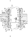
- a shaft seal device according to an embodiment of the present invention will be described with reference to FIG.
- the shaft seal device according to the present embodiment is provided in a pump used in the cooking process of a paper pulp plant.
- the shaft seal device according to the present embodiment seals an annular gap between the shaft 300 and the housing (pump casing) 400.
- the shaft seal device is provided on the first mechanical seal 100 provided on the sealing target fluid side (R) and on the atmosphere side (A) on the opposite side of the first mechanical seal 100 from the sealing target fluid.
- a second mechanical seal 200 is provided.
- the fluid to be sealed in the present embodiment is a cooking liquid (chemical solution) for boiling the chip under high temperature and high pressure.
- a cylindrical sleeve 310 is provided on the outer periphery of the shaft 300 to protect the shaft 300. Further, the first mechanical seal 100 and the second mechanical seal 200 are attached to the outer peripheral side of the sleeve 310.
- a metal seal cover 500 is provided on the outer peripheral side of the first mechanical seal 100 and the second mechanical seal 200.
- the seal cover 500 is fixed to the end surface of the housing 400 together with the protective cover 240 provided on the second mechanical seal 200 by the bolt B.
- the seal cover 500 is provided with a flow path 510 through which a quenching liquid fed into a space region between the first mechanical seal 100 and the second mechanical seal 200 flows.
- This quenching solution is fed into the space area for the purpose of forcibly discharging the fluid to be sealed and blocking the sliding surface from the atmosphere side (A) in addition to lubrication, cooling and cleaning of the sliding surface in the mechanical seal. It is.
- this quenching liquid for example, fresh water can be suitably applied.
- the fluid pressure of the quenching liquid is set to be higher than the fluid pressure of the fluid to be sealed. More specifically, it is set higher by about 0.1 to 0.3 MPa than the fluid pressure of the fluid to be sealed.
- annular gap between the inner circumferential surface of the first mechanical seal 100 and the outer circumferential surface of the sleeve 310, and an annular gap between the outer circumferential surface of the second mechanical seal 200 and the inner circumferential surface of the protective cover 240.
- the quenching liquid is sent into the space area
- the quenching liquid is sent into the shaft seal device from the through hole 241 provided in the protective cover 240.
- the shaft seal device is composed of a plurality of members, and in order to seal the gaps between adjacent members, O-rings O as seal members are provided at a plurality of locations as shown in the figure.
- the second mechanical seal 200 includes a mating ring 210 having a flat sliding surface and a seal ring 220 having an annular convex portion whose tip surface is a sliding surface.
- the mating ring 210 is a rotating ring that is fixed to the shaft 300 side (more specifically, the sleeve 310) and rotates together with the shaft 300.
- the seal ring 220 is a fixed ring that is fixed to the housing 400 side (more specifically, the protective cover 240 fixed to the housing 400 together with the seal cover 500) and does not rotate with the shaft 300.
- the second mechanical seal 200 further includes a compression ring 230 for pressing the mating ring 210 against the seal ring 220 via the O-ring O.
- the compression ring 230 is pressed by a plurality of springs 231 provided at predetermined intervals in the circumferential direction.
- the protective cover 240 described above is provided on the outer peripheral side of the mating ring 210, the seal ring 220, and the compression ring 230.
- the first mechanical seal 100 includes a mating ring 110 having a flat sliding surface and a seal ring 120 having an annular convex portion whose tip surface is a sliding surface.
- the mating ring 110 is a rotating ring that is fixed to the shaft 300 side and rotates together with the shaft 300.
- the mating ring 110 is fixed to a cylindrical metal collar 320 fixed to the outer periphery of the sleeve 310.
- the collar 320 is fixed to the sleeve 310 from the inner peripheral side by a set screw 321 screwed through a through hole 311 provided in the sleeve 310.
- the outer peripheral surface of the collar 320 fixed in this way is covered with the mating ring 110.
- the end surface on the sealing target fluid side (R) of the collar 320 is also covered with the annular member 330 fixed to the shaft 300 so that the entire collar 320 is not exposed to the sealing target fluid. It is configured.
- the seal ring 120 is a stationary ring that is fixed to the housing 400 side (more specifically, a protective cover 140 described later fixed to the housing 400 together with the seal cover 500) and does not rotate with the shaft 300.
- the first mechanical seal 100 further includes a compression ring 130 for pressing the seal ring 120 against the mating ring 110.
- the compression ring 130 is pressed by a plurality of springs 131 provided at a predetermined interval in the circumferential direction.
- a protective cover 140 is provided on the outer peripheral side of the mating ring 110, the seal ring 120, and the compression ring 130.
- the protective cover 140 is configured to be detachable from the seal cover 500, and is configured to be attached to the shaft seal portion as a single component. This point will be described more specifically.
- annular recess 520 into which the end 141 on the atmosphere side (A) of the protective cover 140 is fitted is provided.
- An annular groove 521 having a shallow groove bottom is provided on the inner peripheral surface of the recess 520, and an annular groove 141 a is also provided on the outer peripheral surface of the protective cover 140 that fits into the recess 520. Then, the seal cover 500 and the protective cover 140 are fixed by mounting the O-ring O1, which is a seal member, in an annular space formed by combining these annular grooves 521 and 141a.
- the end portion 141 of the protective cover 140 is attached to the seal cover 500 in a state where the O-ring O1 is attached to the annular groove 141a having a relatively deep groove bottom provided in the protective cover 140. It fits into the concave portion 520.
- the O-ring O1 slides on the inner peripheral surface of the concave portion 520 with the outer circumference reduced in diameter. And when the front-end
- the outer periphery of the O-ring O1 is expanded in diameter, is in close contact with each groove bottom surface of the annular grooves 521, 141a, and is fitted into each of the annular grooves 521, 141a. Accordingly, the seal cover 500 and the protective cover 140 are fixed.
- the protective cover 140 can be removed from the seal cover 500 by applying a force to separate the protective cover 140 from the seal cover 500 so that the end portion 141 of the protective cover 140 is pulled out from the recess 520.
- the protective cover 140 can be easily removed from the seal cover 500 because only a force for elastic deformation is required so that the outer diameter of the O-ring O1 is reduced.
- the seal cover 500 and the protective cover 140 can be easily attached and detached.
- the protective cover 140 is fixed to the seal cover 500, and in a state where these are fixed to the shaft seal portion, the protective cover 140 is adjacent to the sealing target fluid side (R) of the seal cover 500.
- the space between the protective cover 140 and the seal cover 500 is sealed by the O-ring O1 described above.
- the space between the inner peripheral surface of the protective cover 140 and the outer peripheral surface of the seal ring 120 is also sealed by the O-ring O2.
- the protective cover 140 includes an annular protrusion 142 that is configured to protrude toward the fluid to be sealed (R) and that is in close contact with the inner peripheral surface of the housing 400.
- the outer peripheral surface of the annular convex portion 142 and the inner peripheral surface of the housing 400 are also sealed by the two O-rings O.
- the annular protrusion 142 is configured to extend sufficiently to protect the housing 400 on the sealing target fluid side (R).
- the protective cover 140 configured as described above protects the seal cover 500 from being exposed to the fluid to be sealed.
- the mating ring 110, the seal ring 120, and the protective cover 140 are exposed to the fluid to be sealed.
- the mating ring 110, the seal ring 120, and the protective cover 140 are made of a hard material having excellent wear resistance. More specific preferred examples of the hard material include silicon carbide (SiC) and cemented carbide.
- SiC silicon carbide
- cemented carbide The material of these members is not composed of a hard material, but the surface is made of super hard so that a part including a portion exposed to the fluid to be sealed is composed of a hard material having excellent wear resistance.
- a coating may be applied.
- the carbide coating 410 is also applied to the inner peripheral surface of the housing 400 exposed to the fluid to be sealed.
- the mating ring 110 which is a rotating ring fixed to the shaft 300 side, is provided on the fluid to be sealed side (R) and fixed to the housing 400 side.
- the fixed ring is provided on the fluid to be sealed side, and the rotating ring is provided on the side opposite to the fluid to be sealed, so that the annular gap between the inner peripheral surface of the first mechanical seal and the outer peripheral side of the shaft is sealed.
- the space of the annular gap R1 can be freely widened. Then, by widening the space of the annular gap R1, it is possible to suppress the accumulation of solid substances in the annular gap R1, even if solids such as sand are contained in the fluid to be sealed. Since the annular gap R1 can be formed without providing a step on the shaft or sleeve, there is also an advantage that a decrease in strength of the shaft or sleeve can be suppressed.
- the shaft seal device it is possible to suppress the accumulation of solid matter in the annular gap R1, and it is possible to suppress the failure of the operation of the first mechanical seal 100. . Moreover, it can suppress that a solid substance penetrates into the sliding surface (more specifically, the sliding surface of the mating ring 110 and the seal ring 120) in the first mechanical seal 100. Along with this, it is possible to suppress the sliding wear and damage of the sliding surface. In addition, since the fluid to be sealed exists on the outer peripheral surface side of the first mechanical seal 100, it is possible to suppress the solid matter contained in the fluid to be sealed from colliding with the first mechanical seal 100 in a state accompanied by centrifugal force. it can.
- the seal cover 500 is suppressed from being exposed to the fluid to be sealed by the protective cover 140, the deterioration of the seal cover 500 can be suppressed.
- the O-ring O1 is mounted in an annular space formed by combining the annular grooves 521 and 141a provided in the seal cover 500 and the protective cover 140, respectively.
- the structure which can remove 140 easily is employ
- various members that are exposed to the fluid to be sealed include all of them or portions that are exposed to the fluid to be sealed.
- the part is made of a hard material. Therefore, deterioration of these various members can be suppressed. More specifically, generation
- the vicinity of the end surface on the atmosphere side (A) is configured to be suppressed from being exposed to the fluid to be sealed by the annular convex portion 142 provided in the protective cover 140. ing. Therefore, deterioration is particularly suppressed in this vicinity.
- the entire metal collar 320 is configured so as not to be exposed to the fluid to be sealed, it is possible to suppress the occurrence of erosion in the collar 320.
- the collar 320 is fixed to the sleeve 310 from the inner peripheral side by a set screw 321 screwed through a through hole 311 provided in the sleeve 310. Accordingly, the set screw 321 is prevented from coming off by the surface of the shaft 300. In addition, since the set screw 321 is not exposed to the fluid to be sealed, erosion does not occur.
- the shaft seal device As described above, according to the shaft seal device according to the present embodiment, it is possible to extend the life of various members by suppressing the occurrence of erosion due to sand or the like. Also, there are limited parts that can be deteriorated by being exposed to the fluid to be sealed, and the structure must be relatively large and complicated, such as a seal cover having a flow path through which high-pressure fluid flows. There is no need to replace it. Therefore, it is possible to reduce the cost required for replacing the member. Moreover, since it is excellent in maintainability as above-mentioned, the cost accompanying a maintenance can also be reduced.
Landscapes
- Engineering & Computer Science (AREA)
- General Engineering & Computer Science (AREA)
- Mechanical Engineering (AREA)
- Mechanical Sealing (AREA)
Abstract
Description
軸とハウジングとの間の環状隙間を封止する軸封装置であって、
密封対象流体側に備えられる第1メカニカルシールと、
第1メカニカルシールに対して密封対象流体とは反対側に備えられる第2メカニカルシールと、
これら第1メカニカルシール及び第2メカニカルシールの外周側に設けられると共に、第1メカニカルシールと第2メカニカルシールとの間の空間領域に送り込まれる流体であって、かつ密封対象流体よりも高圧の流体が流れる流路を有するシールカバーと、
を備えた軸封装置において、
第1メカニカルシールは、
密封対象流体側に設けられ、かつ内周側が前記軸側に固定されて軸と共に回転する回転環と、
該回転環に対して密封対象流体とは反対側に設けられて該回転環に対して摺動自在に備えられ、かつ軸と共に回転しない固定環と、
を備え、
第1メカニカルシールの外周面側に密封対象流体が存在する環状隙間が形成されると共に、
前記シールカバーの密封対象流体側に隣接し、かつ該シールカバーとの間及び第1メカニカルシールとの間が、それぞれシール部材によって封止された状態で設けられ、前記シールカバーが密封対象流体に曝されるのを抑制する保護カバーを備えることを特徴とする。
該凹部における内周面と前記保護カバーにおける前記凹部に嵌まる部分の外周面には、それぞれ環状溝が設けられており、これらの環状溝が合わさってできる環状の空間にシール部材が装着されることで、前記シールカバーと保護カバーとが固定されるとよい。
前記カラーの外周表面は前記回転環によって覆われており、かつ該カラーは前記スリーブに設けられた貫通孔を介してねじ込まれたセットスクリューによって内周側から該スリーブに固定されているとよい。
図1を参照して、本発明の実施例に係る軸封装置について説明する。なお、本実施例に係る軸封装置は、紙パルププラントの蒸解工程で使用するポンプに設けられるものである。
まず、本実施例に係る軸封装置全体の構成等について説明する。本実施例に係る軸封装置は、軸300とハウジング(ポンプのケーシング)400との間の環状隙間を封止するものである。そして、この軸封装置は、密封対象流体側(R)に備えられる第1メカニカルシール100と、第1メカニカルシール100に対して密封対象流体とは反対側である大気側(A)に備えられる第2メカニカルシール200とを備えている。なお、本実施例における密封対象流体は、チップを高温高圧下で煮るための蒸解液(薬液)である。また、軸300の外周には、軸300を保護するために、円筒形状のスリーブ310が設けられている。また、このスリーブ310の外周側に第1メカニカルシール100及び第2メカニカルシール200が取り付けられている。
第2メカニカルシール200について、より詳細に説明する。第2メカニカルシール200は、平面状の摺動面を有するメイティングリング210と、先端面が摺動面となる環状の凸部を有するシールリング220とを備えている。ここで、メイティングリング210は軸300側(より具体的にはスリーブ310)に固定され、軸300と共に回転する回転環である。また、シールリング220は、ハウジング400側(より具体的にはハウジング400にシールカバー500と共に固定されている保護カバー240)に固定され、軸300と共に回転しない固定環である。
第1メカニカルシール100について、より詳細に説明する。第1メカニカルシール100は、平面状の摺動面を有するメイティングリング110と、先端面が摺動面となる環状の凸部を有するシールリング120とを備えている。
本実施例に係る軸封装置によれば、第1メカニカルシール100において、軸300側に固定される回転環であるメイティングリング110を密封対象流体側(R)に設け、ハウジング400側に固定される固定環であるシールリング120を大気側(A)に設ける構成を採用している。これにより、第1メカニカルシール100の外周面側に密封対象流体が存在する環状隙間R1が形成されるようにしている。
110 メイティングリング
120 シールリング
130 コンプレッションリング
131 スプリング
140 保護カバー
141 端部
141a 環状溝
142 環状凸部
200 第2メカニカルシール
210 メイティングリング
220 シールリング
230 コンプレッションリング
231 スプリング
240 保護カバー
241 貫通孔
300 軸
310 スリーブ
311 貫通孔
320 カラー
321 セットスクリュー
330 環状部材
400 ハウジング
410 超硬コーティング
500 シールカバー
510 流路
520 凹部
521 環状溝
B ボルト
O,O1,O2 Oリング
R1 環状隙間
Claims (5)
- 軸とハウジングとの間の環状隙間を封止する軸封装置であって、
密封対象流体側に備えられる第1メカニカルシールと、
第1メカニカルシールに対して密封対象流体とは反対側に備えられる第2メカニカルシールと、
これら第1メカニカルシール及び第2メカニカルシールの外周側に設けられると共に、第1メカニカルシールと第2メカニカルシールとの間の空間領域に送り込まれる流体であって、かつ密封対象流体よりも高圧の流体が流れる流路を有するシールカバーと、
を備えた軸封装置において、
第1メカニカルシールは、
密封対象流体側に設けられ、かつ内周側が前記軸側に固定されて軸と共に回転する回転環と、
該回転環に対して密封対象流体とは反対側に設けられて該回転環に対して摺動自在に備えられ、かつ軸と共に回転しない固定環と、
を備え、
第1メカニカルシールの外周面側に密封対象流体が存在する環状隙間が形成されると共に、
前記シールカバーの密封対象流体側に隣接し、かつ該シールカバーとの間及び第1メカニカルシールとの間が、それぞれシール部材によって封止された状態で設けられ、前記シールカバーが密封対象流体に曝されるのを抑制する保護カバーを備えることを特徴とする軸封装置。 - 前記シールカバーにおける密封対象流体側の端部には、前記保護カバーにおける密封対象流体とは反対側の端部が嵌まる環状の凹部が設けられており、
該凹部における内周面と前記保護カバーにおける前記凹部に嵌まる部分の外周面には、それぞれ環状溝が設けられており、これらの環状溝が合わさってできる環状の空間にシール部材が装着されることで、前記シールカバーと保護カバーとが固定されることを特徴とする請求項1に記載の軸封装置。 - 前記保護カバーは、その全部または密封対象流体に曝される部分を含む一部が硬質材によって構成されることを特徴とする請求項1または2に記載の軸封装置。
- 前記回転環及び固定環は、これらの全部または密封対象流体に曝される部分を含む一部が硬質材によって構成されることを特徴とする請求項1,2または3に記載の軸封装置。
- 前記軸の外周には、該軸を保護するために取り付けられた円筒形状のスリーブが備えられており、かつ該スリーブの外周には前記回転環を取り付けるためのカラーが備えられると共に、
前記カラーの外周表面は前記回転環によって覆われており、かつ該カラーは前記スリーブに設けられた貫通孔を介してねじ込まれたセットスクリューによって内周側から該スリーブに固定されていることを特徴とする請求項1~4のいずれか一つに記載の軸封装置。
Priority Applications (2)
| Application Number | Priority Date | Filing Date | Title |
|---|---|---|---|
| US13/260,429 US8511689B2 (en) | 2009-03-31 | 2010-02-24 | Shaft sealing apparatus |
| JP2011507061A JP5596017B2 (ja) | 2009-03-31 | 2010-02-24 | 軸封装置 |
Applications Claiming Priority (2)
| Application Number | Priority Date | Filing Date | Title |
|---|---|---|---|
| JP2009086857 | 2009-03-31 | ||
| JP2009-086857 | 2009-03-31 |
Publications (1)
| Publication Number | Publication Date |
|---|---|
| WO2010113573A1 true WO2010113573A1 (ja) | 2010-10-07 |
Family
ID=42827875
Family Applications (1)
| Application Number | Title | Priority Date | Filing Date |
|---|---|---|---|
| PCT/JP2010/052846 Ceased WO2010113573A1 (ja) | 2009-03-31 | 2010-02-24 | 軸封装置 |
Country Status (3)
| Country | Link |
|---|---|
| US (1) | US8511689B2 (ja) |
| JP (1) | JP5596017B2 (ja) |
| WO (1) | WO2010113573A1 (ja) |
Cited By (1)
| Publication number | Priority date | Publication date | Assignee | Title |
|---|---|---|---|---|
| CN106593930A (zh) * | 2016-12-15 | 2017-04-26 | 上海工程技术大学 | 一种悬架式离心泵 |
Families Citing this family (11)
| Publication number | Priority date | Publication date | Assignee | Title |
|---|---|---|---|---|
| EP3017291A4 (en) * | 2013-07-03 | 2017-01-25 | Wyatt Technology Corporation | Method and apparatus to control sample carryover in analytical instruments |
| US9790960B2 (en) | 2014-06-09 | 2017-10-17 | A.R. Wilfley & Sons, Inc. | Centrifugal pump with governor actuated seal |
| JP6509896B2 (ja) * | 2014-11-04 | 2019-05-08 | イーグル工業株式会社 | メカニカルシール装置 |
| CN104879498A (zh) * | 2015-04-15 | 2015-09-02 | 上海高更高实业有限公司 | 超短带有多功能旋转组件集装式机械封密装置 |
| RU2600209C1 (ru) * | 2015-04-29 | 2016-10-20 | Акционерное Общество "Центральное Конструкторское Бюро Машиностроения" | Торцевое уплотнение |
| US10920889B2 (en) | 2016-08-31 | 2021-02-16 | Exxonmobil Chemical Patents Inc. | Rotating shaft mechanical seal |
| CN108662148A (zh) * | 2018-05-28 | 2018-10-16 | 芜湖市中天密封件有限公司 | 一种废料处理用机械密封机构 |
| CN108591463A (zh) * | 2018-05-28 | 2018-09-28 | 芜湖市中天密封件有限公司 | 一种用于废料处理的机械密封件 |
| CN108662147A (zh) * | 2018-05-28 | 2018-10-16 | 芜湖市中天密封件有限公司 | 一种废料处理设备机械密封件 |
| CN109084026A (zh) * | 2018-07-16 | 2018-12-25 | 江苏华本环境科技有限公司 | 一种转轴在壳体外的复合密封结构 |
| US11708831B1 (en) | 2021-09-23 | 2023-07-25 | Parker-Hannifin Corporation | Debris exclusion seal guard for a pump |
Citations (3)
| Publication number | Priority date | Publication date | Assignee | Title |
|---|---|---|---|---|
| JP2003074714A (ja) * | 2001-08-31 | 2003-03-12 | Eagle Ind Co Ltd | メカニカルシール装置 |
| JP2008025654A (ja) * | 2006-07-19 | 2008-02-07 | Koyo Sealing Techno Co Ltd | クランクシャフト用オイルシールの取り付け構造 |
| WO2009008288A1 (ja) * | 2007-07-06 | 2009-01-15 | Eagle Industry Co., Ltd. | メカニカルシール装置 |
Family Cites Families (8)
| Publication number | Priority date | Publication date | Assignee | Title |
|---|---|---|---|---|
| US4421327A (en) * | 1981-12-17 | 1983-12-20 | Morley James P | Heavy duty end face seal with asymmetrical cross-section |
| US4418919A (en) * | 1983-03-01 | 1983-12-06 | Borg-Warner Corporation | Mechanical seals with setting block for use with slurry pumps |
| US4586719A (en) * | 1983-05-19 | 1986-05-06 | Borg-Warner Corporation | Mechanical seal |
| US4691927A (en) * | 1986-12-01 | 1987-09-08 | A. W. Chesterton Company | Temperature-compensating mechanical face seal |
| JP3318389B2 (ja) * | 1992-09-02 | 2002-08-26 | フロウサーヴ・マネジメント・カンパニー | メカニカルシール組立体 |
| US5938205A (en) * | 1997-08-18 | 1999-08-17 | A.W. Chesterton Company | Method and apparatus for optimizing barrier fluid flow for promoting cool running of a cartridge dual seal |
| JP4001594B2 (ja) * | 2004-09-14 | 2007-10-31 | 日本ピラー工業株式会社 | タンデム型ドライコンタクト軸封装置 |
| JP4954167B2 (ja) * | 2008-09-10 | 2012-06-13 | 日本ピラー工業株式会社 | 立軸用メカニカルシール装置 |
-
2010
- 2010-02-24 WO PCT/JP2010/052846 patent/WO2010113573A1/ja not_active Ceased
- 2010-02-24 JP JP2011507061A patent/JP5596017B2/ja not_active Expired - Fee Related
- 2010-02-24 US US13/260,429 patent/US8511689B2/en not_active Expired - Fee Related
Patent Citations (3)
| Publication number | Priority date | Publication date | Assignee | Title |
|---|---|---|---|---|
| JP2003074714A (ja) * | 2001-08-31 | 2003-03-12 | Eagle Ind Co Ltd | メカニカルシール装置 |
| JP2008025654A (ja) * | 2006-07-19 | 2008-02-07 | Koyo Sealing Techno Co Ltd | クランクシャフト用オイルシールの取り付け構造 |
| WO2009008288A1 (ja) * | 2007-07-06 | 2009-01-15 | Eagle Industry Co., Ltd. | メカニカルシール装置 |
Cited By (1)
| Publication number | Priority date | Publication date | Assignee | Title |
|---|---|---|---|---|
| CN106593930A (zh) * | 2016-12-15 | 2017-04-26 | 上海工程技术大学 | 一种悬架式离心泵 |
Also Published As
| Publication number | Publication date |
|---|---|
| JPWO2010113573A1 (ja) | 2012-10-04 |
| US8511689B2 (en) | 2013-08-20 |
| JP5596017B2 (ja) | 2014-09-24 |
| US20120025473A1 (en) | 2012-02-02 |
Similar Documents
| Publication | Publication Date | Title |
|---|---|---|
| JP5596017B2 (ja) | 軸封装置 | |
| CN102112785B (zh) | 机械密封件 | |
| US10544866B2 (en) | Ceramic seal runner and mount for a rotating shaft | |
| WO2011155049A1 (ja) | シールリングおよび船尾管シール装置 | |
| US9488280B2 (en) | Seal assembly | |
| CA2836076C (en) | Carbon seal assembly | |
| JP2015522773A (ja) | 2つの弾性シールを含む、ターボ機械の軸受用のガスケット装置 | |
| JP6140179B2 (ja) | メカニカルシール装置 | |
| WO2009122131A1 (en) | Internally pressurised seals | |
| US9097347B2 (en) | Carbon seal assembly | |
| CN108757550A (zh) | 一种耐腐蚀碱泵用集装式机械密封 | |
| US20070241511A1 (en) | Compact mechanical seal | |
| JP6905152B2 (ja) | 防汚性を向上させた気体潤滑式メカニカルシール | |
| JP5531292B2 (ja) | メカニカルシール | |
| JP5334656B2 (ja) | シール装置 | |
| CN208565057U (zh) | 一种耐腐蚀碱泵用集装式机械密封 | |
| WO2018053560A1 (en) | Dry gland stuffing box | |
| JP5212670B2 (ja) | ウォーターポンプ用密封装置 | |
| US20210033192A1 (en) | Axially preloaded packing ring sets | |
| JP2006322342A (ja) | 水力機械の軸封装置 | |
| JP4646104B2 (ja) | 無注水軸封装置を備えた両吸込形横軸ポンプ | |
| US10036474B2 (en) | Vented lift off seal assemblies | |
| CN209041560U (zh) | 一种机械密封 | |
| JP2006105309A (ja) | 軸受機構および立軸ポンプ | |
| JPS6182074A (ja) | 軸封装置 |
Legal Events
| Date | Code | Title | Description |
|---|---|---|---|
| 121 | Ep: the epo has been informed by wipo that ep was designated in this application |
Ref document number: 10758350 Country of ref document: EP Kind code of ref document: A1 |
|
| WWE | Wipo information: entry into national phase |
Ref document number: 2011507061 Country of ref document: JP |
|
| WWE | Wipo information: entry into national phase |
Ref document number: 13260429 Country of ref document: US |
|
| NENP | Non-entry into the national phase |
Ref country code: DE |
|
| 122 | Ep: pct application non-entry in european phase |
Ref document number: 10758350 Country of ref document: EP Kind code of ref document: A1 |