WO2010113323A1 - カーボン製反応容器の破損防止方法 - Google Patents
カーボン製反応容器の破損防止方法 Download PDFInfo
- Publication number
- WO2010113323A1 WO2010113323A1 PCT/JP2009/056984 JP2009056984W WO2010113323A1 WO 2010113323 A1 WO2010113323 A1 WO 2010113323A1 JP 2009056984 W JP2009056984 W JP 2009056984W WO 2010113323 A1 WO2010113323 A1 WO 2010113323A1
- Authority
- WO
- WIPO (PCT)
- Prior art keywords
- substantially cylindrical
- thermal expansion
- cylindrical body
- carbon
- ring
- Prior art date
- Legal status (The legal status is an assumption and is not a legal conclusion. Google has not performed a legal analysis and makes no representation as to the accuracy of the status listed.)
- Ceased
Links
Images


Classifications
-
- C—CHEMISTRY; METALLURGY
- C04—CEMENTS; CONCRETE; ARTIFICIAL STONE; CERAMICS; REFRACTORIES
- C04B—LIME, MAGNESIA; SLAG; CEMENTS; COMPOSITIONS THEREOF, e.g. MORTARS, CONCRETE OR LIKE BUILDING MATERIALS; ARTIFICIAL STONE; CERAMICS; REFRACTORIES; TREATMENT OF NATURAL STONE
- C04B41/00—After-treatment of mortars, concrete, artificial stone or ceramics; Treatment of natural stone
- C04B41/45—Coating or impregnating, e.g. injection in masonry, partial coating of green or fired ceramics, organic coating compositions for adhering together two concrete elements
- C04B41/50—Coating or impregnating, e.g. injection in masonry, partial coating of green or fired ceramics, organic coating compositions for adhering together two concrete elements with inorganic materials
- C04B41/5053—Coating or impregnating, e.g. injection in masonry, partial coating of green or fired ceramics, organic coating compositions for adhering together two concrete elements with inorganic materials non-oxide ceramics
- C04B41/5057—Carbides
- C04B41/5059—Silicon carbide
-
- B—PERFORMING OPERATIONS; TRANSPORTING
- B01—PHYSICAL OR CHEMICAL PROCESSES OR APPARATUS IN GENERAL
- B01J—CHEMICAL OR PHYSICAL PROCESSES, e.g. CATALYSIS OR COLLOID CHEMISTRY; THEIR RELEVANT APPARATUS
- B01J19/00—Chemical, physical or physico-chemical processes in general; Their relevant apparatus
- B01J19/02—Apparatus characterised by being constructed of material selected for its chemically-resistant properties
-
- B—PERFORMING OPERATIONS; TRANSPORTING
- B01—PHYSICAL OR CHEMICAL PROCESSES OR APPARATUS IN GENERAL
- B01J—CHEMICAL OR PHYSICAL PROCESSES, e.g. CATALYSIS OR COLLOID CHEMISTRY; THEIR RELEVANT APPARATUS
- B01J19/00—Chemical, physical or physico-chemical processes in general; Their relevant apparatus
- B01J19/24—Stationary reactors without moving elements inside
-
- C—CHEMISTRY; METALLURGY
- C04—CEMENTS; CONCRETE; ARTIFICIAL STONE; CERAMICS; REFRACTORIES
- C04B—LIME, MAGNESIA; SLAG; CEMENTS; COMPOSITIONS THEREOF, e.g. MORTARS, CONCRETE OR LIKE BUILDING MATERIALS; ARTIFICIAL STONE; CERAMICS; REFRACTORIES; TREATMENT OF NATURAL STONE
- C04B41/00—After-treatment of mortars, concrete, artificial stone or ceramics; Treatment of natural stone
- C04B41/009—After-treatment of mortars, concrete, artificial stone or ceramics; Treatment of natural stone characterised by the material treated
-
- C—CHEMISTRY; METALLURGY
- C04—CEMENTS; CONCRETE; ARTIFICIAL STONE; CERAMICS; REFRACTORIES
- C04B—LIME, MAGNESIA; SLAG; CEMENTS; COMPOSITIONS THEREOF, e.g. MORTARS, CONCRETE OR LIKE BUILDING MATERIALS; ARTIFICIAL STONE; CERAMICS; REFRACTORIES; TREATMENT OF NATURAL STONE
- C04B41/00—After-treatment of mortars, concrete, artificial stone or ceramics; Treatment of natural stone
- C04B41/80—After-treatment of mortars, concrete, artificial stone or ceramics; Treatment of natural stone of only ceramics
- C04B41/81—Coating or impregnation
- C04B41/85—Coating or impregnation with inorganic materials
- C04B41/87—Ceramics
-
- C—CHEMISTRY; METALLURGY
- C23—COATING METALLIC MATERIAL; COATING MATERIAL WITH METALLIC MATERIAL; CHEMICAL SURFACE TREATMENT; DIFFUSION TREATMENT OF METALLIC MATERIAL; COATING BY VACUUM EVAPORATION, BY SPUTTERING, BY ION IMPLANTATION OR BY CHEMICAL VAPOUR DEPOSITION, IN GENERAL; INHIBITING CORROSION OF METALLIC MATERIAL OR INCRUSTATION IN GENERAL
- C23C—COATING METALLIC MATERIAL; COATING MATERIAL WITH METALLIC MATERIAL; SURFACE TREATMENT OF METALLIC MATERIAL BY DIFFUSION INTO THE SURFACE, BY CHEMICAL CONVERSION OR SUBSTITUTION; COATING BY VACUUM EVAPORATION, BY SPUTTERING, BY ION IMPLANTATION OR BY CHEMICAL VAPOUR DEPOSITION, IN GENERAL
- C23C16/00—Chemical coating by decomposition of gaseous compounds, without leaving reaction products of surface material in the coating, i.e. chemical vapour deposition [CVD] processes
- C23C16/04—Coating on selected surface areas, e.g. using masks
- C23C16/045—Coating cavities or hollow spaces, e.g. interior of tubes; Infiltration of porous substrates
-
- C—CHEMISTRY; METALLURGY
- C23—COATING METALLIC MATERIAL; COATING MATERIAL WITH METALLIC MATERIAL; CHEMICAL SURFACE TREATMENT; DIFFUSION TREATMENT OF METALLIC MATERIAL; COATING BY VACUUM EVAPORATION, BY SPUTTERING, BY ION IMPLANTATION OR BY CHEMICAL VAPOUR DEPOSITION, IN GENERAL; INHIBITING CORROSION OF METALLIC MATERIAL OR INCRUSTATION IN GENERAL
- C23C—COATING METALLIC MATERIAL; COATING MATERIAL WITH METALLIC MATERIAL; SURFACE TREATMENT OF METALLIC MATERIAL BY DIFFUSION INTO THE SURFACE, BY CHEMICAL CONVERSION OR SUBSTITUTION; COATING BY VACUUM EVAPORATION, BY SPUTTERING, BY ION IMPLANTATION OR BY CHEMICAL VAPOUR DEPOSITION, IN GENERAL
- C23C16/00—Chemical coating by decomposition of gaseous compounds, without leaving reaction products of surface material in the coating, i.e. chemical vapour deposition [CVD] processes
- C23C16/22—Chemical coating by decomposition of gaseous compounds, without leaving reaction products of surface material in the coating, i.e. chemical vapour deposition [CVD] processes characterised by the deposition of inorganic material, other than metallic material
- C23C16/30—Deposition of compounds, mixtures or solid solutions, e.g. borides, carbides, nitrides
- C23C16/32—Carbides
- C23C16/325—Silicon carbide
-
- B—PERFORMING OPERATIONS; TRANSPORTING
- B01—PHYSICAL OR CHEMICAL PROCESSES OR APPARATUS IN GENERAL
- B01J—CHEMICAL OR PHYSICAL PROCESSES, e.g. CATALYSIS OR COLLOID CHEMISTRY; THEIR RELEVANT APPARATUS
- B01J2219/00—Chemical, physical or physico-chemical processes in general; Their relevant apparatus
- B01J2219/02—Apparatus characterised by their chemically-resistant properties
- B01J2219/025—Apparatus characterised by their chemically-resistant properties characterised by the construction materials of the reactor vessel proper
- B01J2219/0272—Graphite
Definitions
- the present invention is a method for preventing a carbon reaction vessel in which a plurality of substantially cylindrical bodies made of carbon are connected from being damaged by thermal shock, and particularly a reaction for reacting tetrachlorosilane with hydrogen to convert it to trichlorosilane.
- the present invention relates to a method for preventing damage to a carbon reaction vessel used in a furnace.
- Trichlorosilane (SiHCl 3 ) is a special material gas used for manufacturing semiconductors, liquid crystal panels, solar cells, and the like. In recent years, demand has been steadily expanding, and growth is expected as a CVD material widely used in the electronics field.
- Trichlorosilane is produced by contacting tetrachlorosilane (SiCl 4 ) and hydrogen (H 2 ) to achieve the following thermal equilibrium state. SiCl 4 + H 2 ⁇ SiHCl 3 + HCl (1) This reaction is performed by heating a raw material gas composed of gasified tetrachlorosilane and hydrogen to 700 to 1400 ° C. in a carbon reaction vessel accommodated in a reaction furnace.
- Patent Document 1 proposes a carbon reaction vessel formed by stacking several substantially cylindrical bodies (substantially cylindrical objects) treated with a silicon carbide coating.
- the carbon reaction vessel for reacting tetrachlorosilane with hydrogen is preferably integrally molded to achieve excellent durability and heat transfer efficiency, but it is not suitable for use in production plants. Therefore, as proposed in Patent Document 1, a plurality of carbon substantially cylindrical bodies connected and integrated are used.
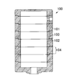
- the inner diameter of the upper end of the substantially cylindrical body 101 is larger than the inner diameter of the body portion 104 in order to stably connect the substantially cylindrical bodies 101 made of carbon.
- the shoulder 102 is formed by the step generated by the difference in inner diameter between the upper end and the body portion 104.
- the outer diameter of the lower end of the substantially cylindrical body 101 is smaller than the outer diameter of the body portion 104.
- the protrusion 103 is formed by a step generated due to a difference in outer diameter with respect to 104.
- the shoulder 102 and the protrusion 103 are arranged so that when the substantially cylindrical bodies 101 are connected to each other, the protrusion 103 of one of the substantially cylindrical bodies 101 is fitted to the shoulder 102 of the other substantially cylindrical body 101.
- the depth of the portion 102 and the length of the protruding portion 103 are designed to be substantially the same.
- a corresponding screw thread or screw groove (not shown) may be provided on the inner peripheral surface of the shoulder portion 102 and the outer peripheral surface of the protruding portion 103. .
- the substantially cylindrical body 101 having the above structure has the shoulder portion 102 and the protruding portion 103 at the upper end and the lower end thereof, the thickness at both ends is reduced to almost half of the body portion 104. As a result, the upper and lower end portions of the substantially cylindrical body 101 become structurally fragile.
- the protrusion 103 of one of the substantially cylindrical bodies and the shoulder 102 of the other substantially cylindrical body at the connecting portion Due to the difference in thermal expansion or thermal shrinkage, the radial stress applied between the two changes. When this stress is remarkably increased, the thin shoulder portion 102 and the protruding portion 103 cannot withstand the load, causing cracks and cracks, which may damage the carbon reaction vessel 100.
- the present invention has been made in view of the above circumstances, and an object of the present invention is to provide a method for preventing a carbon reaction vessel in which a plurality of substantially cylindrical bodies made of carbon are connected from being damaged by thermal shock.
- the present inventors have used a plurality of straight cylindrical substantially cylindrical bodies that do not have shoulders or protrusions, and the connecting parts between these substantially cylindrical bodies are on the outer peripheral side. From the above, it was found that by using a carbon ring, it is possible to suppress the occurrence of cracks in the connecting portion even when a carbon reaction vessel is used in a high heat environment. However, even in this case, using the same material, even if it is a substantially cylindrical body that appears to be the same shape and size, the thermal expansion coefficient differs for each substantially cylindrical body, It has been found that depending on the combination order of the coupling, it may affect the cracking and airtightness of the carbon reaction vessel. In addition, since the carbon ring also thermally expands in the same manner as the substantially cylindrical body, depending on the difference in thermal expansion coefficient from the substantially cylindrical body to be fastened, cracks may occur in the connecting part or the airtightness may be affected. I found.
- the present inventors have previously measured the thermal expansion coefficient of each substantially cylindrical body and ring, and the difference in thermal expansion coefficient between the upper end of one of the substantially cylindrical bodies and the lower end of the other substantially cylindrical body is determined. Arrange the cylinders in order of decreasing size, and fasten the cylinders with a ring that has a small difference in thermal expansion coefficient from the cylinders to prevent the carbon reaction vessel from being damaged by thermal shock. As a result, the inventors have found out that the present invention can be achieved.
- the method for preventing breakage of a carbon reaction vessel comprises connecting a plurality of carbon substantially cylindrical bodies to a coefficient of thermal expansion at the upper end of one of the substantially cylindrical bodies connected to each other and the other substantially cylindrical body.
- the ends are butted together in an order that reduces the difference from the coefficient of thermal expansion at the lower end, and is arranged approximately coaxially.
- the butted ends are fastened with a carbon ring that has a small difference from the coefficient of thermal expansion of the cylindrical body. It is characterized by doing.
- the difference between the thermal expansion amount of one substantially cylindrical body and the thermal expansion amount of the other substantially cylindrical body can be reduced in each connecting portion, and any of the substantially cylindrical bodies can be reduced. Since the difference between the amount of thermal expansion and the amount of thermal expansion of the ring can also be reduced, an increase in stress applied to the connecting portion can be suppressed, and damage to the carbon reaction vessel can be prevented.
- carbon reaction vessel 2 substantially cylindrical body 3: ring 4: canopy 5: bottom plate 6: inlet port 7: outlet 8: connection upper end portion 9: connection lower end portion 100: carbon reaction vessel 101: substantially cylindrical body 102 : Shoulder 103: Protruding part 104: Body part
- the carbon reaction vessel 1 handled in the present embodiment has a plurality of carbon-made substantially cylindrical bodies 2 that are arranged substantially vertically coaxially with their ends abutted to each other. It is configured by screwing and fastening the part with a carbon ring 3 from the outside.
- the substantially cylindrical body arranged at the uppermost stage is closed at the upper end side to constitute the canopy 4 of the carbon reaction container 1, and the substantially cylindrical body arranged at the lowermost stage is closed at the lower end side to be a carbon reaction container.
- 1 bottom plate 5 is formed.
- an introduction port 6 for taking the source gas into the carbon reaction vessel 1 is formed in the approximate center of the bottom plate 5, and the reaction product gas is made of carbon on the side wall of the substantially cylindrical body located near the canopy 4.
- An outlet 7 for leading out of the reaction vessel 1 is formed.
- the carbon reaction vessel 1 In order to generate a reaction product gas containing trichlorosilane and hydrogen chloride from a raw material gas containing tetrachlorosilane and hydrogen, the carbon reaction vessel 1 is heated from the outside with a heater (not shown) and a carbon reaction vessel is produced. 1 is maintained at 700 to 1400 ° C., the raw material gas supplied from the inlet 6 is reacted inside the carbon reaction vessel 1, and the generated reaction product gas is taken out from the outlet 7.
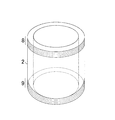
- the substantially cylindrical body 2 has a right cylindrical shape in which male screws are formed on the upper and lower ends involved in the fastening by the ring 3, that is, the outer periphery of the connection upper end portion 8 and the connection lower end portion 9. There are no shoulders or protrusions at the upper end or the lower end like the substantially cylindrical body used in conventional carbon reaction vessels. Therefore, it has an extremely simple shape without large unevenness, and the thickness can be made almost uniform over the entire height direction, so that it has excellent resistance to physical shock and thermal shock.
- the thickness of the substantially cylindrical body 2 is typically preferably 0.5 to 20 cm in order to maintain strength and to avoid peeling of the silicon carbide coating described later on the surface thereof. More preferably, it is 5 cm to 15 cm.
- Male threads for screwing the substantially cylindrical body 2 to the carbon ring 3 are formed on the outer periphery of the upper and lower ends 8 and 9 of the substantially cylindrical body 2.
- the formation width of the male screw is not particularly limited, but is 8/100 or more of the cylindrical height of the substantially cylindrical body 2 in order to ensure the threaded fastening with the ring 3, and further 9 / 100 or more is preferable.
- the direction of winding of the external thread, the number of threads, the shape of the thread, the diameter and the pitch are not particularly limited.
- the material constituting the substantially cylindrical body 2 is preferably a graphite material having excellent airtightness, and particularly has a high strength due to the fine particle structure, and the characteristics such as thermal expansion are the same in any direction. It is preferable to use isotropic high-purity graphite that is also excellent in heat resistance and corrosion resistance.
- the ring 3 is a substantially annular ring in which an internal thread is formed on the inner peripheral surface. Similar to the substantially cylindrical body 2, it has an extremely simple shape without large unevenness and has a substantially uniform thickness, and therefore has excellent resistance to physical and thermal shocks.
- the inner diameter of the ring 3 is substantially cylindrical because it is necessary to be screwed to the external threads provided on the outer periphery of the connecting upper end 8 and the connecting lower end 9 of the cylindrical body 2 by a female screw formed on the inner peripheral surface thereof. 2 is almost the same as the outer diameter.
- the radial width (thickness) of the ring 3 is typically 0.5 to 20 cm, preferably 1 in order to maintain strength and to avoid peeling of the silicon carbide coating described later on the surface. It is preferably 5 cm to 15 cm.
- the width (height) of the ring 3 in the direction of the rotation axis is not to be surely screwed to the connection upper end 8 of the one substantially cylindrical body 2 and the connection lower end 9 of the other substantially cylindrical body 2. Don't be.
- the height of the ring 3 is increased.
- the height is preferably 10/100 or more and 1/2 or less, more preferably 12/100 or more and 1/2 or less, of the cylindrical height of the cylindrical body 2.
- the winding direction, the number of threads, the shape of the thread groove, the diameter, and the pitch of the female screw formed on the inner peripheral surface of the ring 3 are the outer peripheral surfaces of the connected upper end 8 and the connected lower end 9 of the substantially cylindrical body 2 to be connected. It must correspond to the male screw formed on.
- the material constituting the ring 3 is preferably the same as the material constituting the substantially cylindrical body 2 so that the thermal expansion coefficient is not extremely different from that of the substantially cylindrical body 2.
- the silicon carbide film is not particularly limited, but typically can be formed by vapor deposition by a CVD method.
- a silicon halide compound such as tetrachlorosilane or trichlorosilane and a hydrocarbon compound such as methane or propane are used.
- a method using a mixed gas, or a substantially cylinder heated while thermally decomposing a silicon halide compound having a hydrocarbon group such as methyltrichlorosilane, triphenylchlorosilane, methyldichlorosilane, dimethyldichlorosilane, and trimethylchlorosilane with hydrogen.
- a method of depositing silicon carbide on the surfaces of the body 2 and the ring 3 can be used.
- the thickness of the silicon carbide coating is preferably 10 to 500 ⁇ m, more preferably 30 to 300 ⁇ m. If the thickness of the silicon carbide coating is 10 ⁇ m or more, corrosion of the substantially cylindrical body 2 and the ring 3 caused by hydrogen, water, methane, etc. existing in the carbon reaction vessel 1 can be sufficiently suppressed, and if the thickness is 500 ⁇ m or less. In addition, cracks in the silicon carbide coating and cracks in the structure of the substantially cylindrical body 2 and the ring 3 are not promoted.
- the formed silicon carbide coating is a dense homogeneous pinhole-free coating and is excellent in chemical stability. Therefore, the carbon reaction vessel 1 constituted by the substantially cylindrical body 2 and the ring 3 provided with the silicon carbide coating. If the reaction between chlorosilane and hydrogen is carried out, the frequency of repairing the equipment can be reduced, and the work efficiency can be further improved.
- the “thermal expansion coefficient” means the thickness of the upper connecting end 8 of the substantially cylindrical body 2 at the temperature t 0 ° C, the thickness of the lower connecting end 9 or the thickness of the ring 3 at a 0 and the temperature t 1 ° C. the thickness of the connecting upper end portions 8 of the substantially cylindrical body 2, a thickness or thickness of the ring 3 of the connecting bottom portion 9 in the case of the a 1, obtained by the respective following equations (1).
- Thermal expansion coefficient [(a 1 ⁇ a 0 ) / a 0 ] / (t 1 ⁇ t 0 ) (1)
- the substantially cylindrical body 2 and the ring 3 made of carbon are the same as those of the carbon reaction vessel 1.
- the expansion rate with respect to the amount of change in temperature is constant, and thus it is not always necessary to perform measurement by heating to the operating temperature.
- t 0 is 0 to 500 ° C.
- t 1 It is preferable to perform measurement while increasing the ambient temperature at a constant rate using a differential scanning calorimeter under the condition of 400 to 1000 ° C. The measurement is preferably performed in a nitrogen gas atmosphere.
- the coefficient of thermal expansion changes depending on the local compositional difference and dimensional error even in the same substantially cylindrical body 2 and ring 3, and may differ depending on the measurement position.
- the substantially cylindrical body 2 and the ring 3 are manufactured by firing carbon, it is difficult to make the composition and dimensions completely uniform. Accordingly, measurement is performed at a plurality of points on the connection upper end portion 8 of one substantially cylindrical body 2 to obtain an average value thereof, and this average value is set as a thermal expansion coefficient of the connection upper end portion 8 in the approximately cylindrical body 2.
- the substantially cylindrical body 2 and the ring 3 are thermally expanded, their outer diameter and inner diameter increase.
- a gap may be formed in the connecting portion, resulting in poor airtightness.
- the expansion amount of the substantially cylindrical body 2 exceeds the expansion amount of the ring 3 excessively, the stress acting in the radial direction of the connecting portion may increase and cracks may occur.
- the difference in thermal expansion coefficient between the substantially cylindrical bodies 2 connected to each other is large, a gap is formed between the connecting portion and the ring 3, and the source gas and the reaction product gas are outside the carbon reaction vessel. There is a risk of leakage.
- the difference in thermal expansion coefficient between the substantially cylindrical bodies 2 connected to each other is arranged in such an order that the difference in thermal expansion coefficient between the cylindrical bodies 2 is reduced.
- the thermal expansion coefficient at the connecting upper end portion 8 of one of the substantially cylindrical bodies connected to each other and the thermal expansion at the connecting lower end portion 9 of the other substantially cylindrical body is 0.6 ⁇ 10 ⁇ 6 (1 / K) or less, more preferably 0.5 ⁇ 10 ⁇ 6 (1 / K) or less, more preferably 0.4 ⁇ 10 ⁇ 6 (1 / K) or less, more preferably It is preferably 0.3 ⁇ 10 ⁇ 6 (1 / K) or less, more preferably 0.1 ⁇ 10 ⁇ 6 (1 / K) or less.
- the ratio of the thickness of the ring 3 to the thickness of the substantially cylindrical body 2 is 30:70 to 70:30, more preferably 35:65 to 65. : 35, more preferably 40:60 to 60:40, and even more preferably 45:55 to 55:45, the coefficient of thermal expansion of the ring 3 and the connecting upper end 8 and the connecting lower end of the substantially cylindrical body 2
- the difference from the thermal expansion coefficient of the portion 9 is 0.4 ⁇ 10 ⁇ 6 (1 / K) or less, more preferably 0.3 ⁇ 10 ⁇ 6 (1 / K) or less, and further preferably 0.2 ⁇ 10 ⁇ 6 (1 / K).
- connection upper end portion 8 and the connection lower end portion 9 of the substantially cylindrical body 2 it is more preferable to set it to 0.1 ⁇ 10 ⁇ 6 (1 / K) or less.
- coefficient of thermal expansion at the connection upper end portion 8 and the connection lower end portion 9 of the substantially cylindrical body 2 is smaller than the thermal expansion coefficient of the ring 3 in the connection portion. In this case, it is possible to prevent the substantially cylindrical body 2 from being damaged due to excessive stress applied from the horizontal direction to the connection upper end 8 and the connection lower end 9.
- a plurality of substantially cylindrical bodies provided with external threads on the outer peripheral surface of the connecting lower end extending from 3.5 cm to 3.5 cm were prepared.
- the uppermost substantially cylindrical body constituting the canopy of the carbon reaction vessel and the lowermost substantially cylindrical body constituting the bottom plate of the carbon reaction vessel are provided with external threads on the outer peripheral surface of the connection end. .
- a part of the upper end and the lower end of the substantially cylindrical body is collected in advance, and the thermal expansion coefficient corresponding to the connected upper end portion and the connected lower end portion of the substantially cylindrical body from the portion.
- a test piece for measuring was cut out. Four test pieces were prepared for each of the upper end and the lower end in a size of 5 mm in length, 5 mm in width, and 15 mm in height.
- the approximately cylindrical body is placed in a CVD reactor, and the interior of the apparatus is replaced with argon gas, and then heated to 1200 ° C. did.
- a mixed gas of trichloromethylsilane and hydrogen (molar ratio 1: 5) was introduced into the CVD reactor, and a silicon carbide film having a thickness of 200 ⁇ m was formed on the entire surface of the substantially cylindrical body by the CVD method.
- a ring made of isotropic graphite having an inner diameter of 15 cm, an up-and-down width of 7.5 cm, and a radial thickness of 3.6 cm at 25 ° C. (t 0 ) is formed on the inner peripheral surface of the substantially cylindrical body.
- a plurality of rings formed with female threads to be engaged with the formed male threads were prepared, and a silicon carbide coating was applied to the entire surface in the same manner as described above.
- a part of the upper end or the lower end of the ring was collected in advance, and a test piece for measuring the thermal expansion coefficient corresponding to the ring was cut out from the portion.
- the test piece was prepared in a size of 5 mm in length, 5 mm in width, and 15 mm in height, 4 points at a time.
- the atmospheric temperature is kept constant from 25 ° C. (t 0 ) to 1100 ° C. (t 1 ) using a differential scanning calorimeter in a nitrogen gas atmosphere.
- the coefficient of thermal expansion was determined while increasing the speed, and these were used as the coefficient of thermal expansion of the upper and lower ends of each of the substantially cylindrical bodies.
- the coefficient of thermal expansion was determined for the test piece collected from each ring, and this was used as the coefficient of thermal expansion of each ring.
- the cylindrical body is fastened with a ring so that the difference between the average thermal expansion coefficient of the upper end of the connection of the substantially cylindrical body located on the lower side and the average thermal expansion coefficient of the ring is within a certain range shown in Tables 1 and 2.
- a carbon reaction vessel was produced.
- Piping and a heating device were set in the produced carbon reaction vessel to prepare a reaction furnace.
- the amount of the raw material gas and the reaction product gas leaked from the carbon reactor into the reactor was measured to evaluate the airtightness, and then the carbon reactor was disassembled. The occurrence of cracks in the connecting part of the substantially cylindrical body was observed. The results are shown in Tables 1 and 2.
- the thermal expansion coefficient of the connection upper end portion and the connection lower end portion of the substantially cylindrical body in the connection portion is made smaller than the thermal expansion coefficient of the ring, and the thermal expansion coefficient of the ring and the connection upper end portion and connection lower end portion of the substantially cylindrical body. It was confirmed that when the difference from the coefficient of thermal expansion is 0.3 ⁇ 10 ⁇ 6 (1 / K) or less, an increase in stress acting on the connecting portion can be suppressed to an allowable limit or less and airtightness can be maintained.
Landscapes
- Chemical & Material Sciences (AREA)
- Engineering & Computer Science (AREA)
- Organic Chemistry (AREA)
- Ceramic Engineering (AREA)
- Materials Engineering (AREA)
- Chemical Kinetics & Catalysis (AREA)
- Inorganic Chemistry (AREA)
- Structural Engineering (AREA)
- Mechanical Engineering (AREA)
- Metallurgy (AREA)
- General Chemical & Material Sciences (AREA)
- Carbon And Carbon Compounds (AREA)
- Silicon Compounds (AREA)
- Physical Or Chemical Processes And Apparatus (AREA)
Abstract
本発明は、熱膨張による連結部の割れの発生を防止することができる、カーボン製反応容器の破損防止方法に関し、カーボン製の複数の略円筒体を、互いに連結される一方の略円筒体の連結上端部における熱膨張係数と他方の略円筒体の連結下端部における熱膨張係数との差が小さくなるような順序で端部同士を突き合わせて略同軸に配置し、突き合わせ端部を略円筒体の熱膨張係数との差が小さいカーボン製のリングで締結することを特徴とする。
Description
本発明は、カーボンからなる複数の略円筒体を連結したカーボン製反応容器を熱衝撃による破損から防止する方法であって、特にテトラクロロシランと水素とを反応させてトリクロロシランに転換するための反応炉に使用されるカーボン製反応容器の破損防止方法に関する。
トリクロロシラン(SiHCl3)は、半導体、液晶パネル、太陽電池等の製造に用いられる特殊材料ガスである。近年、需要は順調に拡大し、エレクトロニクス分野で広く使用されるCVD材料として、今後も伸びが期待されている。
トリクロロシランは、テトラクロロシラン(SiCl4)と水素(H2)とを接触させ、以下の熱平衡状態を達成することによって生成される。
SiCl4+H2⇔SiHCl3+HCl (1)
この反応は、ガス化したテトラクロロシランと水素とからなる原料ガスを反応炉に収容されたカーボン製反応容器内おいて700~1400℃に加熱することによって行われる。
SiCl4+H2⇔SiHCl3+HCl (1)
この反応は、ガス化したテトラクロロシランと水素とからなる原料ガスを反応炉に収容されたカーボン製反応容器内おいて700~1400℃に加熱することによって行われる。
上記反応によりトリクロロシランを製造するための従来のカーボン製反応容器としては、例えば特許文献1に記載されたものがある。この文献には、炭化珪素被膜処理された数個の略円筒体(略円筒状物)を積み重ねて形成されたカーボン製反応容器が提案されている。
テトラクロロシランと水素とを反応させるためのカーボン製反応容器は、優れた耐久性や伝熱効率を実現するために本来は一体成型されていることが好ましいが、製造プラントで使用される場合には規模が大きくなるため、特許文献1に提案されているように、カーボン製の複数の略円筒体を連結一体化させたものが用いられる。
このようなカーボン製反応容器は、例えば図1に示すように、カーボン製の略円筒体101同士を安定に連結させるために、略円筒体101の上端の内径が胴体部104の内径よりも拡大され、上端と胴体部104との内径差により生じた段差により肩部102が形成され、その一方、略円筒体101の下端の外径が胴体部104の外径より縮小され、下端と胴体部104との外径差により生じた段差により突出部103が形成されている。肩部102と突出部103は、略円筒体101同士を連結する際に、一方の略円筒体101の突出部103が、他方の略円筒体101の肩部102に嵌合するように、肩部102の深さと突出部103の長さとが略同一となるように設計されている。また、略円筒体101同士を螺合締結すべく、肩部102の内周面と突出部103の外周面には、対応するネジ山またはネジ溝(不図示)が設けられている場合もある。
しかしながら、上記構造の略円筒体101は、その上端および下端に肩部102および突出部103を有するため、両端の肉厚が胴体部104のほぼ半分近くにまで薄くなってしまう。その結果、略円筒体101の上下端部が構造上脆くなってしまう。
その上、複数の略円筒体101を連結一体化して使用するため、急激な温度変化を加えると、連結部における一方の略円筒体の突出部103と他方の略円筒体の肩部102との熱膨張量または熱収縮量の相違により、両者間にかかる径方向の応力が変化する。この応力が顕著に増大すると、肉厚の薄い肩部102や突出部103が負荷に耐えきれず割れやひび割れを生じ、カーボン製反応容器100を破損する場合がある。
その上、複数の略円筒体101を連結一体化して使用するため、急激な温度変化を加えると、連結部における一方の略円筒体の突出部103と他方の略円筒体の肩部102との熱膨張量または熱収縮量の相違により、両者間にかかる径方向の応力が変化する。この応力が顕著に増大すると、肉厚の薄い肩部102や突出部103が負荷に耐えきれず割れやひび割れを生じ、カーボン製反応容器100を破損する場合がある。
本発明は上記事情に鑑みてなされたものであり、カーボンからなる複数の略円筒体を連結したカーボン製反応容器を熱衝撃による破損から防止する方法を提供することを目的とする。
本発明者等は、前記課題を解決する方法を鋭意検討した結果、肩部や突出部を有しない複数の直円筒状の略円筒体を用い、これらの略円筒体同士の連結部を外周側からカーボン製のリングを用いて締結することにより、高熱環境下でカーボン製反応容器を使用しても連結部における割れの発生を抑制できることを見出した。
しかしこの場合であっても、同一の材質を用いて、同一の形状および寸法となるように製造された一見同一に見える略円筒体であっても、略円筒体毎に熱膨張係数が異なり、連結の組み合わせ順によってはカーボン製反応容器の割れや気密性に影響を与えることを見出した。また、カーボン製のリングも略円筒体と同様に熱膨張するため、締結する略円筒体との熱膨張係数の相違によっては、連結部に割れを発生したり気密性に影響を与えたりすることを見出した。
しかしこの場合であっても、同一の材質を用いて、同一の形状および寸法となるように製造された一見同一に見える略円筒体であっても、略円筒体毎に熱膨張係数が異なり、連結の組み合わせ順によってはカーボン製反応容器の割れや気密性に影響を与えることを見出した。また、カーボン製のリングも略円筒体と同様に熱膨張するため、締結する略円筒体との熱膨張係数の相違によっては、連結部に割れを発生したり気密性に影響を与えたりすることを見出した。
そこで、本発明者等は、各略円筒体およびリングの熱膨張係数を予め測定しておき、連結する一方の略円筒体の上端と他方の略円筒体の下端との熱膨張係数の差が小さくなるような順序で略円筒体を配置し、略円筒体同士を略円筒体との熱膨張係数の差が小さいリングを用いて締結することにより、カーボン製反応容器を熱衝撃による破損から防止できることを見出し、本発明に至った。
すなわち、本発明のカーボン製反応容器の破損防止方法は、カーボン製の複数の略円筒体を、互いに連結される一方の略円筒体の連結上端部における熱膨張係数と他方の略円筒体の連結下端部における熱膨張係数との差が小さくなるような順序で端部同士を突き合わせて略同軸に配置し、突き合わせ端部を略円筒体の熱膨張係数との差が小さいカーボン製のリングで締結することを特徴とする。
このような構成とすることにより、各連結部において、一方の略円筒体の熱膨張量と他方の略円筒体の熱膨張量との差を低減することができ、しかも、いずれの略円筒体の熱膨張量とリングの熱膨張量との差をも低減することができるため、連結部にかかる応力の増大を抑制でき、カーボン製反応容器の破損を防止することができる。
1: カーボン製反応容器
2: 略円筒体
3: リング
4: 天蓋
5: 底板
6: 導入口
7: 抜出口
8: 連結上端部
9: 連結下端部
100:カーボン製反応容器
101:略円筒体
102:肩部
103:突出部
104:胴体部
2: 略円筒体
3: リング
4: 天蓋
5: 底板
6: 導入口
7: 抜出口
8: 連結上端部
9: 連結下端部
100:カーボン製反応容器
101:略円筒体
102:肩部
103:突出部
104:胴体部
以下、本発明の一実施形態について、図面を用いて説明する。本実施形態では、特に、テトラクロロシランと水素とを含む原料ガスからトリクロロシランと塩化水素とを含む反応生成ガスを生成するために用いられるカーボン製反応容器の破損防止方法について説明する。
本実施形態で扱うカーボン製反応容器1は、図2に示すように、複数のカーボン製の直円筒形状の略円筒体2を、端部同士を突き合わせて略同軸に上下に配し、突き合わせ端部を外側からカーボン製のリング3で螺合締結することにより構成されている。
最上段に配される略円筒体は、上端側が閉塞されていてカーボン製反応容器1の天蓋4を構成し、最下段に配される略円筒体は、下端側が閉塞されていてカーボン製反応容器1の底板5を構成している。また、底板5の略中央には原料ガスをカーボン製反応容器1の内部に取り込むための導入口6が形成され、天蓋4の近傍に位置する略円筒体の側壁には反応生成ガスをカーボン製反応容器1の外部へ導出するための抜出口7が形成されている。
最上段に配される略円筒体は、上端側が閉塞されていてカーボン製反応容器1の天蓋4を構成し、最下段に配される略円筒体は、下端側が閉塞されていてカーボン製反応容器1の底板5を構成している。また、底板5の略中央には原料ガスをカーボン製反応容器1の内部に取り込むための導入口6が形成され、天蓋4の近傍に位置する略円筒体の側壁には反応生成ガスをカーボン製反応容器1の外部へ導出するための抜出口7が形成されている。
テトラクロロシランと水素とを含む原料ガスからトリクロロシランと塩化水素とを含む反応生成ガスを生成するには、このカーボン製反応容器1を外側からヒータ(図示せず)で加熱してカーボン製反応容器1の内部温度を700~1400℃に保ち、導入口6から供給される原料ガスをカーボン製反応容器1の内部で反応させ、生成された反応生成ガスを抜出口7から取り出す。
<略円筒体>
略円筒体2は、図3に示すように、リング3による締結に関与する上下の端部、すなわち連結上端部8および連結下端部9の外周に雄ネジが形成されただけの直円筒形状であり、従来のカーボン製反応容器に用いられていた略円筒体のように上端もしくは下端に肩部や突出部が形成されていない。そのため、大きな凹凸のない極めて単純な形状であるとともに、肉厚をその高さ方向全体にわたってほぼ均一とすることができることから、物理的衝撃や熱的衝撃に対して優れた耐性を有する。
略円筒体2は、図3に示すように、リング3による締結に関与する上下の端部、すなわち連結上端部8および連結下端部9の外周に雄ネジが形成されただけの直円筒形状であり、従来のカーボン製反応容器に用いられていた略円筒体のように上端もしくは下端に肩部や突出部が形成されていない。そのため、大きな凹凸のない極めて単純な形状であるとともに、肉厚をその高さ方向全体にわたってほぼ均一とすることができることから、物理的衝撃や熱的衝撃に対して優れた耐性を有する。
略円筒体2の厚みは、強度を保持するため、並びに、その表面に施す後記の炭化ケイ素被膜の剥離を避けるために、典型的には、0.5~20cmとするのが好ましく、1.5cm~15cmとするのがさらに好ましい。
略円筒体2の連結上端部8および連結下端部9の外周には、それぞれ略円筒体2をカーボン製のリング3に螺合させるための雄ネジが形成されている。雄ネジの形成幅は、特に限定されるものではないが、リング3との螺合締結を確実なものとするために、略円筒体2の円筒高さの8/100以上、さらには9/100以上とするのが好ましい。雄ネジの巻きの方向、条数、ネジ山の形状、径およびピッチは、特に限定されるものではない。
また、略円筒体2を構成する材質としては、気密性に優れた黒鉛材が好ましく、特に、微粒子構造のため強度が高く、熱膨張等の特性がどの方向に対しても同一であることから耐熱性および耐食性にも優れている等方性高純度黒鉛を用いることが好ましい。
<リング>
リング3は、図4に示すように、内周面に雌ネジが形成されただけの略円環状のリングである。略円筒体2と同様に、大きな凹凸のない極めて単純な形状であるとともに、肉厚もほぼ均一であることから、物理的衝撃や熱衝撃に対して優れた耐性を有する。
リング3は、図4に示すように、内周面に雌ネジが形成されただけの略円環状のリングである。略円筒体2と同様に、大きな凹凸のない極めて単純な形状であるとともに、肉厚もほぼ均一であることから、物理的衝撃や熱衝撃に対して優れた耐性を有する。
リング3は、その内周面に形成した雌ネジによって、略円筒体2の連結上端部8および連結下端部9の外周に設けた雄ネジに螺合する必要性から、その内径は略円筒体2の外径とほぼ同一とされる。
リング3の径方向の幅(厚み)は、強度を保持するため、並びに、その表面に施す後記の炭化ケイ素被膜の剥離を避けるために、典型的には、0.5~20cm、好ましくは1.5cm~15cmとするのが好ましい。
リング3の回転軸方向の幅(高さ)は、連結される一方の略円筒体2の連結上端部8および他方の略円筒体2の連結下端部9に確実に螺合するものでなければならない。典型的には、略円筒体2とリング3とを螺合させた場合に、一方の略円筒体2がリング3の高さの半分までしか螺入できないことを考慮して、リング3の高さは、略円筒体2の円筒高さの10/100以上かつ1/2以下、さらには12/100以上かつ1/2以下とすることが好ましい。
リング3の内周面に形成される雌ネジの巻きの方向、条数、ネジ溝の形状、径およびピッチは、連結される略円筒体2の連結上端部8および連結下端部9の外周面に形成された雄ネジに対応するものでなければならない。
また、リング3を構成する材質は、熱膨張係数において略円筒体2と極端に相違しないよう、略円筒体2を構成する材質と同一であることが好ましい。
<表面処理>
略円筒体2およびリング3は、カーボンを主材料とするため、カーボン製反応容器1内に供給される水素や、水素の燃焼により生成する水によって、以下に示すように、組織の減肉または脆化を受けてしまう。
C+2H2→CH4
C+H2O→H2+CO
C+2H2O→2H2+CO2
炭化ケイ素被膜はこれらの化学的分解に対して極めて耐性が高いため、カーボン製の略円筒体2およびリング3の表面に炭化ケイ素被膜を形成することが好ましい。
略円筒体2およびリング3は、カーボンを主材料とするため、カーボン製反応容器1内に供給される水素や、水素の燃焼により生成する水によって、以下に示すように、組織の減肉または脆化を受けてしまう。
C+2H2→CH4
C+H2O→H2+CO
C+2H2O→2H2+CO2
炭化ケイ素被膜はこれらの化学的分解に対して極めて耐性が高いため、カーボン製の略円筒体2およびリング3の表面に炭化ケイ素被膜を形成することが好ましい。
炭化ケイ素被膜は、特に制限はないが、典型的にはCVD法により蒸着させて形成することができる。
CVD法によりカーボン製の略円筒体2およびリング3の表面に炭化ケイ素被膜を形成するには、例えば、テトラクロロシラン又はトリクロロシランのようなハロゲン化珪素化合物とメタンやプロパンなどの炭化水素化合物との混合ガスを用いる方法、またはメチルトリクロロシラン、トリフェニルクロロシラン、メチルジクロロシラン、ジメチルジクロロシラン、トリメチルクロロシランのような炭化水素基を有するハロゲン化珪素化合物を水素で熱分解しながら、加熱された略円筒体2およびリング3の表面に炭化ケイ素を堆積させる方法を用いることができる。
CVD法によりカーボン製の略円筒体2およびリング3の表面に炭化ケイ素被膜を形成するには、例えば、テトラクロロシラン又はトリクロロシランのようなハロゲン化珪素化合物とメタンやプロパンなどの炭化水素化合物との混合ガスを用いる方法、またはメチルトリクロロシラン、トリフェニルクロロシラン、メチルジクロロシラン、ジメチルジクロロシラン、トリメチルクロロシランのような炭化水素基を有するハロゲン化珪素化合物を水素で熱分解しながら、加熱された略円筒体2およびリング3の表面に炭化ケイ素を堆積させる方法を用いることができる。
炭化ケイ素被膜の厚みは、10~500μmとすることが好ましく、30~300μmであればさらに好ましい。炭化ケイ素被膜の厚みが10μm以上であれば、カーボン製反応容器1内に存在する水素、水、メタン等による略円筒体2およびリング3の腐食を十分に抑制でき、また、500μm以下であれば、炭化ケイ素被膜のひび割れや略円筒体2およびリング3の組織の割れが助長されることもない。
形成された炭化ケイ素被膜は、緻密均質なピンホールのない被膜であり、化学安定性に優れているため、炭化ケイ素被膜を施した略円筒体2およびリング3により構成されたカーボン製反応容器1中でクロロシランと水素との反応を行えば、設備の修繕頻度を低減でき、作業能率をさらに向上させることができる。
<熱膨張係数>
本明細書において、「熱膨張係数」とは、温度t0℃における略円筒体2の連結上端部8の厚み、連結下端部9の厚みまたはリング3の厚みをa0、温度t1℃における略円筒体2の連結上端部8の厚み、連結下端部9の厚みまたはリング3の厚みをa1とした場合に、それぞれ以下の式(1)によって求められる。
熱膨張係数=[(a1-a0)/a0]/(t1-t0) (1)
熱膨張係数を求めるには、カーボン製反応容器1の運転条件に近い条件下で熱膨張量の測定を行うことが好ましいが、カーボンからなる略円筒体2およびリング3はカーボン製反応容器1の通常運転条件である1400℃以下のいずれの温度帯域であっても、温度変化量に対する膨張率は一定であるため、必ずしも運転温度まで加熱して測定を行う必要はない。テトラクロロシランと水素とを含む原料ガスからトリクロロシランと塩化水素とを含む反応生成ガスを生成するためのカーボン製反応容器として使用する場合、具体的には、t0を0~500℃、t1を400~1000℃とする条件で、示差走査熱量計を用いて雰囲気温度を一定速度で上昇させながら測定することが好ましい。また、測定は窒素ガス雰囲気中で行うことが好ましい。
本明細書において、「熱膨張係数」とは、温度t0℃における略円筒体2の連結上端部8の厚み、連結下端部9の厚みまたはリング3の厚みをa0、温度t1℃における略円筒体2の連結上端部8の厚み、連結下端部9の厚みまたはリング3の厚みをa1とした場合に、それぞれ以下の式(1)によって求められる。
熱膨張係数=[(a1-a0)/a0]/(t1-t0) (1)
熱膨張係数を求めるには、カーボン製反応容器1の運転条件に近い条件下で熱膨張量の測定を行うことが好ましいが、カーボンからなる略円筒体2およびリング3はカーボン製反応容器1の通常運転条件である1400℃以下のいずれの温度帯域であっても、温度変化量に対する膨張率は一定であるため、必ずしも運転温度まで加熱して測定を行う必要はない。テトラクロロシランと水素とを含む原料ガスからトリクロロシランと塩化水素とを含む反応生成ガスを生成するためのカーボン製反応容器として使用する場合、具体的には、t0を0~500℃、t1を400~1000℃とする条件で、示差走査熱量計を用いて雰囲気温度を一定速度で上昇させながら測定することが好ましい。また、測定は窒素ガス雰囲気中で行うことが好ましい。
熱膨張係数は、同一の略円筒体2およびリング3であっても、局所的な組成の相違や寸法の誤差によって変化するため、測定する位置によって相違する場合がある。特に略円筒体2およびリング3はカーボンを焼成することによって製造されるため、その組成や寸法を完全に均一にすることは難しい。
そこで、1つの略円筒体2の連結上端部8について複数点で測定を行い、これらの平均値を求め、この平均値をその略円筒体2における連結上端部8の熱膨張係数とすることが好ましい。同様に、連結下端部9およびリング3の熱膨張係数についても平均値を求めることが好ましい。連結上端部8、連結下端部9またはリング3の熱膨張係数として、それぞれの平均値を用いることにより、このような測定位置による熱膨張係数のバラツキの影響を低減することができる。
そこで、1つの略円筒体2の連結上端部8について複数点で測定を行い、これらの平均値を求め、この平均値をその略円筒体2における連結上端部8の熱膨張係数とすることが好ましい。同様に、連結下端部9およびリング3の熱膨張係数についても平均値を求めることが好ましい。連結上端部8、連結下端部9またはリング3の熱膨張係数として、それぞれの平均値を用いることにより、このような測定位置による熱膨張係数のバラツキの影響を低減することができる。
<カーボン製反応容器の組み立ておよび破損防止方法>
予め熱膨張係数を求めた複数の略円筒体2について、一方の略円筒体の連結上端部8における熱膨張係数と、他方の略円筒体の連結下端部9における熱膨張係数との差が小さくなるような順序を決定し、これらの端部同士を突き合わせて略同軸に配置し、さらに、連結するいずれの略円筒体2と比べても熱膨張係数の差が小さいカーボン製のリング3を用いて略円筒体の突き合わせ端部を締結する。
予め熱膨張係数を求めた複数の略円筒体2について、一方の略円筒体の連結上端部8における熱膨張係数と、他方の略円筒体の連結下端部9における熱膨張係数との差が小さくなるような順序を決定し、これらの端部同士を突き合わせて略同軸に配置し、さらに、連結するいずれの略円筒体2と比べても熱膨張係数の差が小さいカーボン製のリング3を用いて略円筒体の突き合わせ端部を締結する。
一般に、略円筒体2およびリング3が熱膨張すると、その外径および内径が増加する。その結果、リング3の膨張量が略円筒体2の膨張量を過度に上回ると連結部に隙間が生じて気密性が悪くなる場合がある。一方、略円筒体2の膨張量がリング3の膨張量を過度に上回ると連結部の径方向に作用する応力が増大して割れを発生する場合がある。また、互いに連結する略円筒体2間の熱膨張係数の差が大きいと、連結部においてリング3との間に隙間を生じることになり、原料ガスや反応生成ガスがカーボン製反応容器の外に漏れるおそれがある。
そこで、このように、互いに連結する略円筒体2同士の熱膨張係数の差が小さくなるような順序に配置して、連結するいずれの略円筒体2と比べても熱膨張係数の差が小さいリング3を用いて締結することにより、連結部に作用する応力の増大を許容限界以下に抑制することができるとともに、連結部の気密性を向上させることができる。
具体的には、連結部の気密性を十分に維持するために、互いに連結される一方の略円筒体の連結上端部8における熱膨張係数と他方の略円筒体の連結下端部9における熱膨張係数との差を0.6x10⁻⁶(1/K)以下、さらに好ましくは0.5x10-6(1/K)以下、さらに好ましくは0.4x10-6(1/K)以下、さらに好ましくは0.3x10-6(1/K)以下、さらに好ましくは0.1x10-6(1/K)以下とすることが好ましい。
また、連結部に作用する応力の増大を許容限界以下に抑制するために、リング3の厚み:略円筒体2の厚みの比が30:70~70:30、さらに好ましくは35:65~65:35、さらに好ましくは40:60~60:40、さらに好ましくは45:55~55:45の範囲である場合に、リング3の熱膨張係数と略円筒体2の連結上端部8および連結下端部9の熱膨張係数との差を0.4x10⁻⁶(1/K)以下、さらに好ましくは0.3x10-6(1/K)以下、さらに好ましくは0.2x10-6(1/K)以下、さらに好ましくは0.1x10-6(1/K)以下とすることが好ましい。
とりわけ、連結部において、略円筒体2の連結上端部8および連結下端部9における熱膨張係数が、リング3の熱膨張係数より小さいことが好ましい。この場合には、連結上端部8および連結下端部9に水平方向から過度の応力がかかることによる略円筒体2の破損を防止することができる。
とりわけ、連結部において、略円筒体2の連結上端部8および連結下端部9における熱膨張係数が、リング3の熱膨張係数より小さいことが好ましい。この場合には、連結上端部8および連結下端部9に水平方向から過度の応力がかかることによる略円筒体2の破損を防止することができる。
以上、図面を参照して本発明の実施形態について述べたが、これらは本発明の例示であり、上記以外の様々な構成を採用することもできる。
以下、本発明を実施例によりさらに説明するが、本発明はこれらに限定されるものではない。
25℃(t0)において外径15cm、高さ10cm、厚さ3cmの等方性黒鉛からなる直円筒状の略円筒体であって、上端から3.5cmにわたる連結上端部の外周面および下端から3.5cmにわたる連結下端部の外周面に雄ネジが設けられた略円筒体を複数準備した。また、カーボン製反応容器の天蓋を構成する最上段の略円筒体、並びにカーボン製反応容器の底板を構成する最下段の略円筒体についても同様に、連結端部外周面に雄ネジを設けた。一方、略円筒体の加工を行う前に、略円筒体の上端および下端の一部を予め採取しておき、当該部位からその略円筒体の連結上端部および連結下端部に対応する熱膨張係数を測定するための試験片を切り出した。試験片は、上端および下端のそれぞれについて、縦5mm、幅5mm、高さ15mmの大きさで4点ずつ準備した。
次いで、これらの略円筒体の内周面および外周面に炭化ケイ素被膜を形成するために、略円筒体をCVD反応装置内に設置し、装置内部をアルゴンガスで置換したのち、1200℃に加熱した。CVD反応装置内にトリクロロメチルシランと水素の混合ガス(モル比1:5)を導入し、CVD法により、略円筒体の全表面に200μmの厚みの炭化ケイ素被膜を形成した。
次に、25℃(t0)において内径15cm、上下方向の幅7.5cm、径方向の厚み3.6cmの等方性黒鉛からなるリングであって、内周面に前記略円筒体に形成された雄ネジと螺合する雌ネジが形成されたリングを複数準備し、上記と同様にその全表面に炭化ケイ素被膜を施した。また、リングの加工を行う前に、リングの上端もしくは下端の一部を予め採取しておき、当該部位からそのリングに対応する熱膨張係数を測定するための試験片を切り出した。試験片は、縦5mm、幅5mm、高さ15mmの大きさで4点ずつ準備した。
各略円筒体の連結上端部および連結下端部に対応する試験片について、窒素ガス雰囲気下で、示差走査熱量計を用いて雰囲気温度を25℃(t0)~1100℃(t1)まで一定速度で上昇させながら熱膨張係数を求め、これらを各略円筒体の連結上端部および連結下端部の熱膨張係数とした。同様に、各リングから採取した試験片について熱膨張係数を求め、これを各リングの熱膨張係数とした。
得られた略円筒体およびリングを、互いに連結する一方の略円筒体の連結上端部の平均熱膨張係数と他方の略円筒体の連結下端部の平均熱膨張係数との差、並びに、連結部において下側に位置する略円筒体の連結上端部の平均熱膨張係数とリングの平均熱膨張係数との差が表1および2に示す一定の範囲となるように略円筒体をリングで締結し、カーボン製反応容器を製造した。
製造したカーボン製反応容器に配管及び加熱装置等をセットして反応炉として整えた。
この反応炉にテトラクロロシランと水素(モル=1:1)の混合ガスを供給し、常圧、反応温度1100℃で反応を行い、トリクロロシランを生成した。
反応炉を連続的に2000時間運転した後、カーボン製反応容器から反応炉内に漏れ出した原料ガスおよび反応生成ガスの量を測定して気密性を評価した後、カーボン製反応容器を解体して略円筒体の連結部における割れの発生を観察した。結果を表1および2に示す。
この反応炉にテトラクロロシランと水素(モル=1:1)の混合ガスを供給し、常圧、反応温度1100℃で反応を行い、トリクロロシランを生成した。
反応炉を連続的に2000時間運転した後、カーボン製反応容器から反応炉内に漏れ出した原料ガスおよび反応生成ガスの量を測定して気密性を評価した後、カーボン製反応容器を解体して略円筒体の連結部における割れの発生を観察した。結果を表1および2に示す。

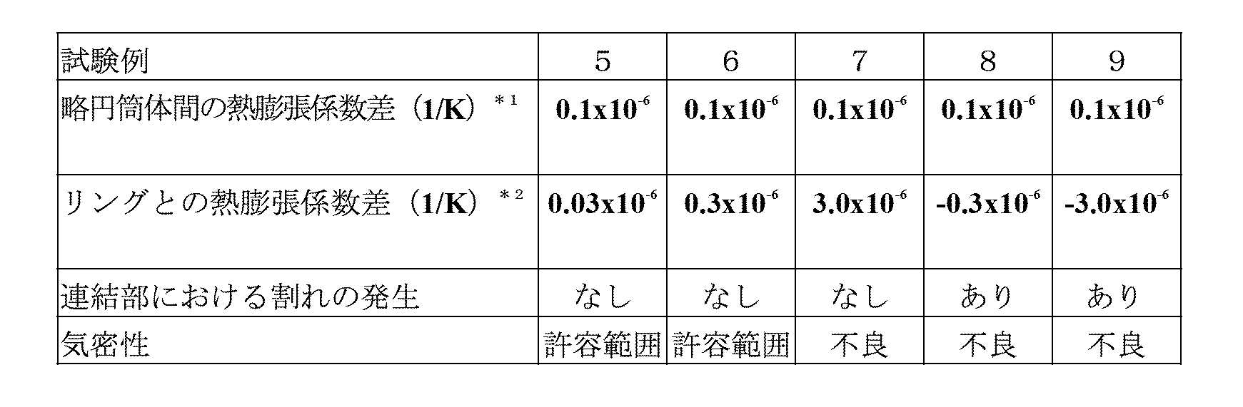
*1略円筒体間の熱膨張係数差=[連結部において上側に位置する略円筒体の連結下端部の熱膨張係数]-[連結部において下側に位置する略円筒体の連結上端部の熱膨張係数]
*2リングとの熱膨張係数差=[リングの熱膨張係数]-[連結部において下側に位置する略円筒体の連結上端部の熱膨張係数]
<実験の考察>
以上の結果から、互いに連結される一方の略円筒体の連結上端部における熱膨張係数と他方の略円筒体の連結下端部における熱膨張係数との差を0.1x10⁻⁶(1/K)以下とすることによって、気密性が向上することが確認された。
以上の結果から、互いに連結される一方の略円筒体の連結上端部における熱膨張係数と他方の略円筒体の連結下端部における熱膨張係数との差を0.1x10⁻⁶(1/K)以下とすることによって、気密性が向上することが確認された。
また、連結部における略円筒体の連結上端部および連結下端部の熱膨張係数をリングの熱膨張係数より小さくして、しかも、リングの熱膨張係数と略円筒体の連結上端部および連結下端部の熱膨張係数との差を0.3x10⁻⁶(1/K)以下とすることにより、連結部に作用する応力の増大を許容限界以下に抑制でき、気密性も保持できることが確認された。
以上、本発明を実施例に基づいて説明した。この実施例はあくまで例示であり、種々の変形例が可能なこと、またそうした変形例も本発明の範囲にあることは当業者に理解されるところである。
Claims (5)
- カーボン製の複数の略円筒体を、互いに連結される一方の略円筒体の連結上端部における熱膨張係数と他方の略円筒体の連結下端部における熱膨張係数との差が小さくなるような順序で端部同士を突き合わせて略同軸に配置し、突き合わせ端部を略円筒体の熱膨張係数との差が小さいカーボン製のリングで締結する、カーボン製反応容器の破損防止方法。
- 略円筒体が黒鉛製である、請求項1記載のカーボン製反応容器の破損防止方法。
- 略円筒体の内周面および/または外周面が炭化ケイ素被膜処理されている、請求項1記載のカーボン製反応容器の破損防止方法。
- 互いに連結される一方の略円筒体の連結上端部における熱膨張係数と他方の略円筒体の連結下端部における熱膨張係数との差が0.1x10⁻⁶(1/K)以下である、請求項1記載のカーボン製反応容器の破損防止方法。
- リングの厚み:略円筒体の厚みが30:70~70:30の範囲である場合に、リングの熱膨張係数よりも略円筒体の連結上端部および連結下端部の熱膨張係数の方が小さく、かつ、リングの熱膨張係数と略円筒体の連結上端部および連結下端部の熱膨張係数との差が0.3x10⁻⁶(1/K)以下である、請求項1記載のカーボン製反応容器の破損防止方法。
Priority Applications (3)
| Application Number | Priority Date | Filing Date | Title |
|---|---|---|---|
| PCT/JP2009/056984 WO2010113323A1 (ja) | 2009-04-03 | 2009-04-03 | カーボン製反応容器の破損防止方法 |
| JP2011506946A JP5436542B2 (ja) | 2009-04-03 | 2009-04-03 | カーボン製反応容器の破損防止方法 |
| TW099102348A TW201036914A (en) | 2009-04-03 | 2010-01-28 | Damage prevention method of reaction vessel made of carbon |
Applications Claiming Priority (1)
| Application Number | Priority Date | Filing Date | Title |
|---|---|---|---|
| PCT/JP2009/056984 WO2010113323A1 (ja) | 2009-04-03 | 2009-04-03 | カーボン製反応容器の破損防止方法 |
Publications (1)
| Publication Number | Publication Date |
|---|---|
| WO2010113323A1 true WO2010113323A1 (ja) | 2010-10-07 |
Family
ID=42827651
Family Applications (1)
| Application Number | Title | Priority Date | Filing Date |
|---|---|---|---|
| PCT/JP2009/056984 Ceased WO2010113323A1 (ja) | 2009-04-03 | 2009-04-03 | カーボン製反応容器の破損防止方法 |
Country Status (3)
| Country | Link |
|---|---|
| JP (1) | JP5436542B2 (ja) |
| TW (1) | TW201036914A (ja) |
| WO (1) | WO2010113323A1 (ja) |
Cited By (2)
| Publication number | Priority date | Publication date | Assignee | Title |
|---|---|---|---|---|
| JP5374581B2 (ja) * | 2009-04-03 | 2013-12-25 | 電気化学工業株式会社 | カーボン製反応容器の破損防止方法 |
| JP2020026370A (ja) * | 2018-08-10 | 2020-02-20 | イビデン株式会社 | 反応装置 |
Citations (4)
| Publication number | Priority date | Publication date | Assignee | Title |
|---|---|---|---|---|
| JPH02282687A (ja) * | 1989-04-21 | 1990-11-20 | Nippon Steel Corp | 竪型マッフル式熱処理炉のマッフルの支持方法 |
| JPH09157073A (ja) * | 1995-12-01 | 1997-06-17 | Denki Kagaku Kogyo Kk | カーボン製反応容器 |
| JP2003327437A (ja) * | 2002-05-13 | 2003-11-19 | Sumitomo Electric Ind Ltd | 加熱炉 |
| JP2008137885A (ja) * | 2006-11-07 | 2008-06-19 | Mitsubishi Materials Corp | トリクロロシランの製造方法およびトリクロロシラン製造装置 |
-
2009
- 2009-04-03 WO PCT/JP2009/056984 patent/WO2010113323A1/ja not_active Ceased
- 2009-04-03 JP JP2011506946A patent/JP5436542B2/ja active Active
-
2010
- 2010-01-28 TW TW099102348A patent/TW201036914A/zh unknown
Patent Citations (4)
| Publication number | Priority date | Publication date | Assignee | Title |
|---|---|---|---|---|
| JPH02282687A (ja) * | 1989-04-21 | 1990-11-20 | Nippon Steel Corp | 竪型マッフル式熱処理炉のマッフルの支持方法 |
| JPH09157073A (ja) * | 1995-12-01 | 1997-06-17 | Denki Kagaku Kogyo Kk | カーボン製反応容器 |
| JP2003327437A (ja) * | 2002-05-13 | 2003-11-19 | Sumitomo Electric Ind Ltd | 加熱炉 |
| JP2008137885A (ja) * | 2006-11-07 | 2008-06-19 | Mitsubishi Materials Corp | トリクロロシランの製造方法およびトリクロロシラン製造装置 |
Cited By (3)
| Publication number | Priority date | Publication date | Assignee | Title |
|---|---|---|---|---|
| JP5374581B2 (ja) * | 2009-04-03 | 2013-12-25 | 電気化学工業株式会社 | カーボン製反応容器の破損防止方法 |
| JP2020026370A (ja) * | 2018-08-10 | 2020-02-20 | イビデン株式会社 | 反応装置 |
| JP7093264B2 (ja) | 2018-08-10 | 2022-06-29 | イビデン株式会社 | 反応装置 |
Also Published As
| Publication number | Publication date |
|---|---|
| TW201036914A (en) | 2010-10-16 |
| JP5436542B2 (ja) | 2014-03-05 |
| JPWO2010113323A1 (ja) | 2012-10-04 |
Similar Documents
| Publication | Publication Date | Title |
|---|---|---|
| CA2104411C (en) | Chemical vapor deposition-production silicon carbide having improved properties | |
| USRE42887E1 (en) | Silicon carbide and other films and method of deposition | |
| KR20100126569A (ko) | 화학 증착 반응기의 가스 분배 시스템 및 방법 | |
| JP3529070B2 (ja) | カーボン製反応容器 | |
| Kim et al. | Effect of diluent gases on growth behavior and characteristics of chemically vapor deposited silicon carbide films | |
| US10358741B2 (en) | Seed material for liquid phase epitaxial growth of monocrystalline silicon carbide, and method for liquid phase epitaxial growth of monocrystalline silicon carbide | |
| JP5436542B2 (ja) | カーボン製反応容器の破損防止方法 | |
| US6190725B1 (en) | Coating method for the preparation of coated nuclear fuels with carbides borides or nitrides by using high temperature and high pressure combustion synthesis | |
| JP5374581B2 (ja) | カーボン製反応容器の破損防止方法 | |
| WO2002060834A1 (fr) | Procede d'assemblage de pieces en ceramique de haute purete | |
| TW202242208A (zh) | 碳化矽塗佈基底基板、其之碳化矽基板、及其方法 | |
| US8440566B2 (en) | Method for forming an aluminum nitride thin film | |
| US3961003A (en) | Method and apparatus for making elongated Si and SiC structures | |
| JP5412447B2 (ja) | 炭素含有材料からなる反応容器を備える反応装置、その反応装置の腐食防止方法およびその反応装置を用いたクロロシラン類の生産方法 | |
| JP5553754B2 (ja) | カーボン製反応容器 | |
| WO2010016133A1 (ja) | カーボン製反応装置 | |
| KR102553973B1 (ko) | 반응기를 위한 서셉터 배열체 및 반응기를 위한 공정 기체의 가열 방법 | |
| JP7544671B2 (ja) | 炭化タンタル被覆炭素材料 | |
| JP5436454B2 (ja) | 発熱装置 | |
| Danielsson et al. | Reducing stress in silicon carbide epitaxial layers | |
| AU2005257313B2 (en) | Tubular container made of carbon | |
| CN119546805A (zh) | 用于生产SiC固体材料的方法和装置 | |
| US20220144710A1 (en) | Method for preparing silicon-carbide-silicon-nitride composite material, and silicon-carbide-silicon-nitride composite material according to same | |
| WO2024228309A1 (ja) | 炭化金属被覆炭素材料 |
Legal Events
| Date | Code | Title | Description |
|---|---|---|---|
| 121 | Ep: the epo has been informed by wipo that ep was designated in this application |
Ref document number: 09842677 Country of ref document: EP Kind code of ref document: A1 |
|
| WWE | Wipo information: entry into national phase |
Ref document number: 2011506946 Country of ref document: JP |
|
| NENP | Non-entry into the national phase |
Ref country code: DE |
|
| 122 | Ep: pct application non-entry in european phase |
Ref document number: 09842677 Country of ref document: EP Kind code of ref document: A1 |