WO2010110195A1 - 光加熱による廃棄物の溶融装置及び方法 - Google Patents
光加熱による廃棄物の溶融装置及び方法 Download PDFInfo
- Publication number
- WO2010110195A1 WO2010110195A1 PCT/JP2010/054762 JP2010054762W WO2010110195A1 WO 2010110195 A1 WO2010110195 A1 WO 2010110195A1 JP 2010054762 W JP2010054762 W JP 2010054762W WO 2010110195 A1 WO2010110195 A1 WO 2010110195A1
- Authority
- WO
- WIPO (PCT)
- Prior art keywords
- waste
- treated
- rod
- light heating
- light
- Prior art date
- Legal status (The legal status is an assumption and is not a legal conclusion. Google has not performed a legal analysis and makes no representation as to the accuracy of the status listed.)
- Ceased
Links
Images
Classifications
-
- B—PERFORMING OPERATIONS; TRANSPORTING
- B01—PHYSICAL OR CHEMICAL PROCESSES OR APPARATUS IN GENERAL
- B01J—CHEMICAL OR PHYSICAL PROCESSES, e.g. CATALYSIS OR COLLOID CHEMISTRY; THEIR RELEVANT APPARATUS
- B01J19/00—Chemical, physical or physico-chemical processes in general; Their relevant apparatus
- B01J19/08—Processes employing the direct application of electric or wave energy, or particle radiation; Apparatus therefor
- B01J19/12—Processes employing the direct application of electric or wave energy, or particle radiation; Apparatus therefor employing electromagnetic waves
- B01J19/122—Incoherent waves
- B01J19/128—Infrared light
-
- B—PERFORMING OPERATIONS; TRANSPORTING
- B01—PHYSICAL OR CHEMICAL PROCESSES OR APPARATUS IN GENERAL
- B01J—CHEMICAL OR PHYSICAL PROCESSES, e.g. CATALYSIS OR COLLOID CHEMISTRY; THEIR RELEVANT APPARATUS
- B01J2219/00—Chemical, physical or physico-chemical processes in general; Their relevant apparatus
- B01J2219/02—Apparatus characterised by their chemically-resistant properties
- B01J2219/025—Apparatus characterised by their chemically-resistant properties characterised by the construction materials of the reactor vessel proper
- B01J2219/0263—Ceramic
-
- B—PERFORMING OPERATIONS; TRANSPORTING
- B01—PHYSICAL OR CHEMICAL PROCESSES OR APPARATUS IN GENERAL
- B01J—CHEMICAL OR PHYSICAL PROCESSES, e.g. CATALYSIS OR COLLOID CHEMISTRY; THEIR RELEVANT APPARATUS
- B01J2219/00—Chemical, physical or physico-chemical processes in general; Their relevant apparatus
- B01J2219/08—Processes employing the direct application of electric or wave energy, or particle radiation; Apparatus therefor
- B01J2219/0873—Materials to be treated
- B01J2219/0879—Solid
-
- B—PERFORMING OPERATIONS; TRANSPORTING
- B09—DISPOSAL OF SOLID WASTE; RECLAMATION OF CONTAMINATED SOIL
- B09B—DISPOSAL OF SOLID WASTE NOT OTHERWISE PROVIDED FOR
- B09B2101/00—Type of solid waste
- B09B2101/35—Asbestos
Definitions
- the present invention relates to an apparatus for melting and detoxifying a waste to be treated by light heating capable of safely detoxifying a waste to be treated including asbestos-containing materials that are said to be easily scattered and have a great effect on health.
- the present invention relates to a melt detoxification method using this.
- Asbestos which has excellent heat resistance and wear resistance, and has been used in large quantities in building materials and industrial materials, has been pointed out as a serious health hazard to humans and has been removed. There is a need for immediate removal from the social sphere.
- asbestos due to its excellent properties, especially heat resistance and chemical resistance, asbestos is difficult to dispose of, and at present, when asbestos-containing materials are recovered at the site of building demolition work, repair work, etc., it is strictly double packed And then transported by each means of transportation and landfilled at a predetermined managed waste disposal site.
- the amount of sprayable asbestos, such as spraying materials, in Japan is estimated to be less than 1 million tons with an asbestos mixing ratio of 1% or more in terms of weight.
- Volatile components adhering to the inner wall of the cylindrical tube are often substances that absorb light more easily (having a higher emissivity) than quartz tubes, and selectively absorb light and become hotter than cylindrical tubes.
- the inner wall of the tube reacts with its constituent material (for example, quartz), and the transparent cylindrical tube may become clouded or crystallized, and the light transmittance may be further deteriorated and the strength may be deteriorated. If it does so, the subject that the case where effective light heating will become very difficult will arise. Further, since the invention disclosed in Japanese Patent Application No. 2008-168137 is a local heating method, energy consumption is advantageous as compared to other methods, but since it is local heating, the rod-shaped disposal waste Accurate position control of objects is essential.
- the melting and detoxifying treatment apparatus for waste to be treated by light heating is made of a material that is structurally stable at 1000 ° C. or less and has little energy absorption for heat rays including infrared rays, and is parallel to the vertical direction.
- a cylindrical member disposed on the cylindrical member, a supply mechanism for supplying the waste material to be treated from the upper part of the tubular member downward, a light source disposed around the tubular member and radiating heat rays including infrared rays, and a light source emitted from the light source.
- a light heating mechanism for locally raising the temperature of the rod-shaped waste to be treated that is supplied into the cylinder, and the light heating mechanism locally for the rod-shaped waste to be treated.
- An observation mechanism that directly observes the heated part from the outside of the tube and the light heating mechanism at a wavelength in the infrared region, and by sucking in or discharging the surrounding air into the tube, From bottom to top, the flow rate is 20 liters. Since it is configured with a gas discharge mechanism or a gas suction mechanism that creates an air flow that flows at a flow rate of 1 liter / minute or more, the observation mechanism, the light heating mechanism, and the gas discharge mechanism or the gas suction mechanism are functionally linked to perform observation.
- the electric power applied to the light source of the light heating mechanism can be adjusted from the observation results obtained from the mechanism, and the air flow generated in the cylindrical material can be adjusted, preventing the attachment of volatile components to the inner wall of the cylindrical material, Because it is possible to accurately control the position of the processing waste, the waste to be processed is melted and detoxified by light heating continuously for a long time to ensure that the waste to be processed is melted and made harmless. can do. This ensures that the entire waste to be treated can be melted, the entire waste to be treated is liquefied, and the fine structure of the substance that has harmful effects can be destroyed and converted into a harmless structure. it can.
- the apparatus for melting and detoxifying the waste to be treated by light heating is provided such that the inner diameter R of the cylindrical material and the outer diameter r of the rod-shaped waste to be treated have a conditional expression of R / r ⁇ 1.8.
- the inner wall of the cylindrical material can be effectively prevented from being contaminated by various volatile components generated in the process of melting the rod-shaped waste to be processed by light heating. It is possible to continuously pass the light from the inside of the cylinder material for a long time, and reliably carry out the melting and detoxification treatment of the waste to be treated by light heating for a long time. Melt detoxification treatment can be performed.
- the state of the locally heated portion of the rod-shaped waste to be treated obtained from the observation mechanism and the state of the wall surface of the cylindrical member are observed and evaluated, and the air flow flowing in the cylindrical member is evaluated. If it is configured with a control device that controls the flow rate, the supply speed of the rod-shaped waste to be processed, and the power applied to the light source of the light heating mechanism, the flow rate of the air flow flowing through the cylindrical material, the supply of the rod-shaped waste to be treated.
- a control device that controls the flow rate, the supply speed of the rod-shaped waste to be processed, and the power applied to the light source of the light heating mechanism, the flow rate of the air flow flowing through the cylindrical material, the supply of the rod-shaped waste to be treated
- Each of the speed and the power applied to the light source of the light heating mechanism can be controlled to ensure that the melting and detoxifying treatment of the waste to be treated by light heating can be performed continuously for a long time, and therefore Since it is possible to accurately control the position of the rod-shaped waste to be treated, the waste to be
- the waste to be treated for melting by light heating as described above is used.
- a detoxification treatment method for waste to be treated by light heating that can efficiently and safely and reliably and further meet the demand for cost reduction. It becomes possible.
- a device for melting and detoxifying a waste to be treated by light heating is a molding device (not shown) provided with an extrusion molding device necessary for molding a rod-shaped waste to be treated 2.
- a movable device 3 serving as a supply mechanism for supplying the molded rod-shaped waste material 2 to the lower part of the cylindrical tube 1 as a tubular material, and the rod-shaped waste material to be treated supplied by the movable device 3 2 is provided with a light heating mechanism 4 for locally raising the temperature.
- the light heating mechanism 4 is disposed around the cylindrical tube 1 and includes a light source 41 that emits heat rays including infrared rays, and a reflecting mirror 42 that reflects the heat rays emitted from the light source 41. And a control device 7 having a control mechanism for adjusting the strength of the power supplied from the power source.
- the cylindrical tube 1 uses a quartz tube made of quartz.
- the molding apparatus (not shown) includes, for example, a waste to be treated and a recovery hopper into which additives such as a solidifying material, a combustion auxiliary material, and a melting point lowering material added to the waste to be treated are placed, Conveying pipe for mixing and transporting treated waste and additive, extrusion device for extruding mixed treated waste and additive, and molding for molding treated waste and additive extruded from this extrusion device
- This is an extrusion molding apparatus composed of a mold, and is used to mold the mixed waste to be treated and the additive into the rod-shaped waste to be treated 2 by the mold.
- the light heating mechanism 4 is disposed around the cylindrical tube 1 and locally heats and melts the rod-shaped waste to be treated 2 supplied by the movable device 3.
- a light source 41 that radiates and a reflecting mirror 42 that reflects heat rays emitted from the light source 41 are provided.
- a halogen lamp may be used as the light source 41
- a mirror body having a spheroid with gold plating may be used as the reflecting mirror 42, for example.
- the reflecting mirrors 42 are used by being arranged on the left and right with respect to the focal point, and collect the light of the light source 41 locally on the rod-shaped waste to be treated 2.
- a gas generator 5 as a gas discharge mechanism or a gas suction mechanism is connected to a connecting portion 51 at the lower end of the cylindrical tube 1, sucks ambient air, and discharges air into the cylindrical tube 1, thereby the cylindrical tube 1. Air is flowed from the lower portion to the upper portion at a flow rate of 20 liters / minute or more to create an air flow in the cylindrical tube 1.
- the gas discharge mechanism or the gas suction mechanism illustrated and described as the gas generator 5 in the present embodiment can be connected to the lower end portion of the cylindrical tube 1, and the air flow is performed at a flow rate of 20 liters / minute or more. As long as it can be produced, a known one may be used.
- the imaging device 6 has a portion of the rod-shaped waste 2 to be locally heated by the light heating mechanism 4 and a wall surface portion of the cylindrical tube 1 outside the cylindrical tube 1 and the light heating mechanism 4 in the infrared region.
- a color CCD video camera in which an ND filter or sunglasses is arranged in front of the imaging unit may be used.
- the control device 7 includes a power source that supplies the applied power to the light source 41, and is a control device that adjusts the applied power to adjust the intensity of light. From the evaluation of the state of the locally heated portion of the waste 2 and the state of the wall surface of the cylindrical tube 1, the flow rate of the air flow flowing through the cylindrical tube 1 and the supply speed of the rod-shaped waste 2 are controlled.
- a control device having a control function For example, the power applied to the light source 41 of the light heating mechanism 4 is changed from the above evaluation to adjust the intensity of the light, and the flow rate of the air flow flowing through the cylindrical tube 1 is set to a condition that the flow rate is 20 liters / min or more from the above evaluation.
- the melt detoxification processing apparatus of the waste to be processed by light heating has a relationship between the inner diameter R of the cylindrical tube 1 and the outer diameter r of the rod-shaped waste to be processed 2 molded in a molding mold in advance.
- R / r ⁇ 1.8 is configured, and the inner wall of the cylindrical tube 1 is prevented from being contaminated by various volatile components generated by light heating of the rod-shaped waste to be treated 2.
- melt detoxification method using the melt detoxification apparatus for waste to be treated by light heating according to the present invention will be described with reference to FIG.
- the rod-shaped waste 2 is molded by a molding apparatus.
- a robot-shaped waste to be treated 2 is engaged with the suspension member 32 of the movable device 3, and then the motor and the rotational motion of the movable device 3 are linearly moved.
- the speed can be adjusted by the motion replacement mechanism 31 that replaces the light and is supplied into the cylindrical tube 1 that absorbs less energy with respect to light including infrared rays.
- the rod-shaped waste to be treated 2a supplied into the cylindrical tube 11, particularly the local area thereof, is heated by irradiation with light collected by the light source 41 and the reflecting mirror 42 of the light heating mechanism 4.
- the heated rod-shaped waste 2 to be processed melts and liquefies by itself when it reaches its melting point.
- the gas generating device 5 is connected to the connecting portion 51 at the lower end of the cylindrical tube 1, and air flows through the cylindrical tube 1 from the lower part to the upper part at a flow rate of 20 liters / minute or more (air flow). Forming step 1D).
- the cylindrical tube 1 In order to observe the state of the wall surface of the tube and evaluate whether or not the desired melt detoxification process is being performed in the light heating step 1D by the control device 7, and further to perform the desired melt detoxification process, The flow rate of the airflow flowing through the tube 1, the supply speed of the rod-shaped waste 2, and the power applied to the light source 41 are controlled. Under the control of the control device, in the supplying process 1B, the light heating process 1C, and the air flow forming process 1D, each process reflecting the control is advanced.
- the experimental conditions were changed by changing the power applied to the light heating mechanism 4, the outer diameter r of the rod-shaped waste 2 to be treated, and the flow rate of air flowing using the gas discharge mechanism.
- the inner diameter of the cylindrical tube 1 is 50 mm
- the rod-shaped waste 2 is made of rock wool, cement, water-absorbing polymer, and the weight of the rock wool is 100 parts by weight. What was mixed at a ratio of parts by weight and 1 part by weight of the water-absorbing polymer was poured into a rod-shaped mold and molded.
- the asbestos-containing rod-shaped waste 2 has not been adopted for safety reasons.
- the shape of the representative rod-shaped waste 2 is assumed to be a cylindrical shape having a length of 100 mm and an outer diameter of 18 mm.
- a method of light heating As a method of light heating, a method of starting light heating by focusing on the lower end of the rod-shaped waste to be treated 2, a method of lowering the rod-shaped waste to be treated 2 toward a heating zone near the lower focal point, and the like are assumed.
- Table 1 a method of starting heating with focusing on the lower end of the rod-shaped waste to be treated was adopted.
- the melting and detoxification treatment apparatus for waste to be treated by light heating and the detoxification treatment method using the same according to the present invention it is structurally stable at 1000 ° C. or less and absorbs energy with respect to heat rays including infrared rays.
- a quartz cylindrical tube 1 made of a material with a small amount of material is disposed in parallel to the vertical direction, and the rod-shaped processing waste is disposed while controlling the supply speed of the movable device 3 by the control device 7 from the upper part of the cylindrical tube 1 downward. While the object 2 is supplied and the power applied to the light source 41 is controlled by the control device 7, the light is collected by the light source 41 and the reflecting mirror 42 of the light heating mechanism 4 to locally raise the temperature of the rod-shaped waste 2 to be treated.
- the inner diameter R of the cylindrical tube 1 and the outer diameter r of the rod-shaped waste to be treated 2 are configured so as to satisfy the conditional expression of R / r ⁇ 1.8. It is possible to effectively prevent the inner wall of the cylindrical tube 1 from being contaminated by various volatile components generated during the melting process of the object 2, and allow the light from the light source 41 to continuously pass into the cylindrical tube 1 for a long time. It becomes possible to carry out the melting and detoxification treatment of the waste to be treated by light heating reliably for a long period of time and to melt and detoxify the waste to be treated.
- the refrigerant 8a for cooling the light source 41 and the reflecting mirror 42 and the exhaust heat absorbed by the refrigerant 8a are used to obtain a high temperature necessary for forming the rod-shaped waste to be treated 2 using the heat exchanger 8. Since it is used as a heat source or used as a heat source for raising the temperature of an air flow created by the gas generator 5, the waste-to-be-treated waste detoxification treatment apparatus by light heating according to the present invention is heat or electric power. Can be used efficiently, and it is possible to meet market demands such as energy saving and reduction of running cost.
- the embodiment assuming the asbestos-containing material as the rod-shaped waste to be processed is illustrated, but the waste to be processed is not limited to the asbestos-containing material.
- the cylindrical material is exemplified as a cylindrical tube, but the inner diameter R of the cylindrical tube and the outer diameter r of the rod-shaped waste to be processed are provided with a conditional expression of R / r ⁇ 1.8.
- the cross-sectional shape Is not necessarily circular.
Landscapes
- Chemical & Material Sciences (AREA)
- Physics & Mathematics (AREA)
- Electromagnetism (AREA)
- Health & Medical Sciences (AREA)
- General Health & Medical Sciences (AREA)
- Toxicology (AREA)
- Organic Chemistry (AREA)
- Chemical Kinetics & Catalysis (AREA)
- Processing Of Solid Wastes (AREA)
Abstract
本発明は、光加熱により被処理廃棄物を長時間継続的に加熱し、溶融無害化することを目的とするものであって、円筒管(1)の内径Rと棒状被処理廃棄物(2)の外径rとの関係を、R/r≧1.8とした下で、1000℃以下で構造的に安定で、赤外線を含む熱線に対してエネルギー吸収が少ない材料からなる石英の円筒管(1)内に、制御装置(7)で可動装置(3)の供給速度を制御しながら棒状被処理廃棄物(2)を供給し、円筒管(1)の下部から上部へ、制御装置(7)で20リットル/分以上の条件下にて流量を制御しながらガス発生装置(5)により空気を流して空気流を作るとともに、制御装置(7)で光源(41)への印加電力を制御しながら、光加熱機構(4)の光源(41)および反射鏡(42)により集光して棒状被処理廃棄物(2)を局所的に昇温して溶融する。
Description
本発明は、飛散しやすく健康に影響が大きいといわれるアスベスト含有物をはじめとする被処理廃棄物を安全に無害化処理することが可能な光加熱による被処理廃棄物の溶融無害化処理装置およびこれを用いた溶融無害化処理方法に関する。
耐熱耐磨耗などに優れ、建築材料、工業材料に大量に使用されてきたアスベストは、人体への重大な健康被害が指摘され、除去が進んでいるが、最近の社会的な要請により、人間社会の生活圏からの速やかな除去が求められている。しかし、その優れた性質、特に、耐熱性と耐薬品性ゆえに、アスベストは処分が難しく、現状、建物の解体工事現場、改修工事現場等でアスベスト含有物が回収されると、厳重に二重梱包した袋に詰められ、各輸送手段で運搬され、所定の管理型廃棄物処分場で埋め立て処分されている。
吹きつけ材などの飛散性アスベストの日本国内の存在量は、アスベスト混入比が重量換算で1%以上のもので100万トン弱と見積もられているが、最近の規制強化によりその対象が重量比1%以上から0.1%以上に厳格化されたため、その10倍以上存在するという見積もりもある。このため、極めて近い将来、現在稼働している処分場にて処分できる量に限界がくることが明白となっている。
さらに、飛散性アスベスト廃棄物の運搬時には、袋詰めされたアスベスト含有物が漏洩しないように厳重な防護対策が必要となるほか、処分場に至る運搬経路において多数の許可申請が必要とされるなど、最終処分までに要する労力が極めて大きいことが指摘されている。また、廃棄物処分場を必要な数だけ新しく増設することは、当然、その近傍で生活する住民の反対が予想され、極めて困難となることが確実視されている。
吹きつけ材などの飛散性アスベストの日本国内の存在量は、アスベスト混入比が重量換算で1%以上のもので100万トン弱と見積もられているが、最近の規制強化によりその対象が重量比1%以上から0.1%以上に厳格化されたため、その10倍以上存在するという見積もりもある。このため、極めて近い将来、現在稼働している処分場にて処分できる量に限界がくることが明白となっている。
さらに、飛散性アスベスト廃棄物の運搬時には、袋詰めされたアスベスト含有物が漏洩しないように厳重な防護対策が必要となるほか、処分場に至る運搬経路において多数の許可申請が必要とされるなど、最終処分までに要する労力が極めて大きいことが指摘されている。また、廃棄物処分場を必要な数だけ新しく増設することは、当然、その近傍で生活する住民の反対が予想され、極めて困難となることが確実視されている。
一方、2005年以降、アスベスト含有廃棄物を溶融処理施設に持ち込み、高温で溶融して、アスベストを無害化する方法が開発されている。アスベストの繊維状形態は、その融点以上の高温にすることで完全に消失し、通常のアルミニウムやマグネシウムの酸化物となり、特に、アスベストの中で一番融点が高いのはクリソタイルで、その融点が約1500℃であるので、1600℃以上の高温状態にすれば、全てのアスベスト(6種類が知られている)を完全に溶融し、その繊維状形態を消失させることが可能であることが広く知られている。そして、例えば、下記特許文献1から特許文献3にてアスベスト含有物の無害化処理に係る発明が提案されている。
特許文献1にて提案された発明では、溶融施設の建設コストおよびランニングコストが膨大になるとともに、建設スペースの確保が困難であるという問題などが解決されていない。さらに、施設自体が残存アスベスト廃棄物の量に比べて少ないという問題もある。アスベスト廃棄物の運搬時における二重の袋詰め、アスベスト含有物が漏洩しないような厳重な防護対策、処分場に至る運搬経路において多数の許可申請など、運搬時に関する時間と労力が極めて大きい問題についても何ら解決されていないという問題がある。
また、上記特許文献2または上記特許文献3に提案された発明では、アスベストをリン酸化合物やカルシウム化合物等により、他の物質形態に化学処理するのだが、建築物の壁、天井などある一定程度の厚みを有するアスベストに普遍的に浸透する等などし、すべてのアスベストを変質させることができるか否かについて疑義が生じる。さらに、健康被害をもたらさない程度にアスベストを変質させることが可能になるとしても、既存の施工状態に半永久的に処理したアスベストが存在することになり、経年的な信頼性の問題が新たに生ずるという課題もある。
したがって、アスベスト除去工事現場等において、最も危険度の高い吹付けアスベストを除去して回収し、袋詰めしたアスベスト含有物を、当該現場から搬出するまでに無害化することができれば、処分場、溶融施設の問題が解決され、厳重な袋詰め等も不要となって、無害な一般廃棄物として処分することが可能となる。さらに、無害化処理したアスベスト含有物について減容化を図ることができれば、廃棄物の容量が少なくなり、一般廃棄物として廃棄するのに要する運搬時の輸送作業なども少なくて済むことが期待できる。
すなわち、従来のアスベスト含有物の無害化方法では、溶融施設の場合、建設コスト及びランニングコストが膨大なものとなるとともに、施設自体が少なく、溶融施設に持ち込むまでの運搬に係る問題は、何ら解決されていないという問題がある。既存の施工状態においてアスベストを他の物質形態に化学処理する方法では、すべてのアスベストを変質させることができるか否かについて疑義が生じ、また、既存の施工状態に存在する半永久的なアスベストに対する、経年的な信頼性の問題が生じている。これらの問題を解決するため、本出願人らは、特願2008-168137において、光源および反射鏡を有する加熱溶融処理装置により、工事現場などから搬出するまでに溶融処理し無害化する被処理廃棄物の溶融無害化処理装置とその方法に係る発明を提案している。
具体的には、鉛直に取り付けた円筒管内に、押出成型機によって棒状に成形されたアスベスト含有廃棄物を円筒管上部から下方に供給し、円筒管の周囲に配置され、光源と反射鏡とからなる光加熱機構からの光を局所的に棒状のアスベスト廃棄物上で集光、加熱して溶融処理し無害化するものであるが、さらに、光源からの光を円筒管内部へ長時間継続的に被処理廃棄物に照射することにより、被処理廃棄物の溶融無害化処理の効率性、確実性の向上を図ることなどの要請が生じている。
具体的には、鉛直に取り付けた円筒管内に、押出成型機によって棒状に成形されたアスベスト含有廃棄物を円筒管上部から下方に供給し、円筒管の周囲に配置され、光源と反射鏡とからなる光加熱機構からの光を局所的に棒状のアスベスト廃棄物上で集光、加熱して溶融処理し無害化するものであるが、さらに、光源からの光を円筒管内部へ長時間継続的に被処理廃棄物に照射することにより、被処理廃棄物の溶融無害化処理の効率性、確実性の向上を図ることなどの要請が生じている。
被処理廃棄物の溶融無害化処理の効率性、確実性の向上については、例えば、鉛直に取り付けた円筒管の実施形態として、透明な石英管が採用されることが想定され、石英管内に供給される棒状の被処理廃棄物を石英管の管壁を通して1600℃以上の高温まで局所光加熱するのだが、棒状の被処理廃棄物から様々な揮発成分が発生し、石英管などの円筒管内壁に付着するため、光源からの光を円筒管内部へ長時間継続的に通過させることが困難となるおそれがある。円筒管内壁に付着した揮発成分は、石英管に比べて光を吸収しやすい(放射率が大きい)物質であることが多く、選択的に光を吸収して円筒管に比べて高温となり、円筒管内壁でその構成材料(例えば、石英)と反応し、透明な円筒管が白濁、結晶化し、さらなる光透過率の悪化、及び強度が劣化するおそれもある。そうすると、効果的な光加熱が極めて困難となる場合が想定されるという課題が生じる。
また、特願2008-168137に開示した発明は、局所的な加熱方法であるため、消費エネルギーが他の方法に比べて有利である一方、局所的な加熱であることから、棒状の被処理廃棄物の正確な位置制御が必須となる。そして、所望の溶融無害化処理を行うためには、特願2008-168137に開示の押出成型機の押出供給速度を処理中の被処理廃棄物の溶融状態の計測にもとづいて制御する制御機構のほか、円筒管内に発生させる空気流と光加熱機構の光源に印加する電力とを併せて制御する別の制御機構を備えることが有効であるので、これらの要求を満たす技術開発が必要であるという課題があった。
また、特願2008-168137に開示した発明は、局所的な加熱方法であるため、消費エネルギーが他の方法に比べて有利である一方、局所的な加熱であることから、棒状の被処理廃棄物の正確な位置制御が必須となる。そして、所望の溶融無害化処理を行うためには、特願2008-168137に開示の押出成型機の押出供給速度を処理中の被処理廃棄物の溶融状態の計測にもとづいて制御する制御機構のほか、円筒管内に発生させる空気流と光加熱機構の光源に印加する電力とを併せて制御する別の制御機構を備えることが有効であるので、これらの要求を満たす技術開発が必要であるという課題があった。
本発明は、上記実情に鑑み提案されたもので、建物の解体工事現場、改修工事現場等において、アスベスト含有物をはじめとする被処理廃棄物を溶融無害化処理する溶融無害化処理装置とその方法に関し、光加熱装置からの光を、効率よくアスベスト含有廃棄物に長時間継続的に集光させるとともに、円筒管内に発生させる空気流と光加熱機構の光源に印加する電力とを併せて制御する制御機構なども備えさせて、被処理廃棄物を確実に溶融無害化処理することができ、被処理廃棄物の溶融無害化処理を効率性よく、確実かつ安全に進めることが可能な被処理廃棄物の溶融無害化処理装置およびこれを用いた溶融無害化処理方法を提供することを目的とする。
上記目的を達成するために、本発明に係る光加熱による被処理廃棄物の溶融無害化処理装置は、1000℃以下で構造的に安定で、赤外線を含む熱線に対してエネルギー吸収が少ない材料からなり、鉛直方向に対して平行に配置される筒材と、この筒材の上部から下方に、棒状被処理廃棄物を供給する供給機構と、前記筒材の周囲に配置され、前記赤外線を含む熱線を放射する光源およびこの光源から発せられた熱線を反射する反射鏡を有し、前記筒材内に供給される前記棒状被処理廃棄物を局所的に昇温する光加熱機構と、この光加熱機構によって前記棒状被処理廃棄物の局所的に昇温させられた部分を、前記筒材および前記光加熱機構の外側から赤外線領域の波長で直接観察する観察機構と、周囲の空気を吸入または前記筒材内へ空気を排出することにより、前記筒材内を下部から上部へ、流量20リットル/分以上で流れる空気流を作る気体排出機構または気体吸入機構と、を備えることを特徴とする。
特に、上記光加熱による被処理廃棄物の溶融無害化処理装置は、R/r≧1.8(但し、R:筒材の内径、r:棒状被処理廃棄物の外径)の条件式を具備する、ことが好ましい。
また、光源および反射鏡を冷却するための冷媒と、この冷媒に吸収された排熱を、棒状被処理廃棄物の成形に必要な高温を得るための熱源に使用する、或いは、気体排出機構または気体吸入機構により作られる空気流を昇温するための熱源に使用する熱交換機とを備えることが、さらに好ましい。
さらに、観察機構から得られる棒状被処理廃棄物の局所的に昇温させられた部分の状態と筒材の壁表面の状態とを観察し、評価して、筒材内を流れる空気流の流量、棒状被処理廃棄物の供給速度、光加熱機構の光源に印加する電力を制御する制御装置を備えることが、さらにまた好ましい。
そして、本発明に係る光加熱による被処理廃棄物の溶融無害化処理方法は、上記被処理廃棄物の溶融無害化処理装置を用いる、ことを特徴とする。
すなわち、本発明は、筒材内に発生させる空気流と光加熱機構の光源に印可する電力とを併せて制御する制御機構を備えること、および、これを補強するための各種機構を備えることにより、光加熱による被処理廃棄物の溶融無害化処理を長時間継続的に実行して、被処理廃棄物を効率よく、安全かつ確実に溶融無害化処理する手段を提供するものである。
本発明では、光加熱による被処理廃棄物の溶融無害化処理装置を、1000℃以下で構造的に安定で、赤外線を含む熱線に対してエネルギー吸収が少ない材料からなり、鉛直方向に対して平行に配置される筒材と、この筒材の上部から下方に、棒状被処理廃棄物を供給する供給機構と、筒材の周囲に配置され、赤外線を含む熱線を放射する光源およびこの光源から発せられた熱線を反射する反射鏡を有し、筒材内に供給される棒状被処理廃棄物を局所的に昇温する光加熱機構と、この光加熱機構によって棒状被処理廃棄物の局所的に昇温させられた部分を、筒材および光加熱機構の外側から赤外線領域の波長で直接観察する観察機構と、周囲の空気を吸入または筒材内へ空気を排出することにより、筒材内を下部から上部へ、流量20リットル/分以上で流れる空気流を作る気体排出機構または気体吸入機構とを備えて構成したので、観察機構と光加熱機構と気体排出機構または気体吸入機構とを機能的に連動させることにより、観察機構から得られた観察結果から光加熱機構の光源に印可する電力を調整するとともに、筒材内に発生させる空気流を調整することができ、筒材内壁への揮発成分の付着防止、棒状被処理廃棄物の正確な位置制御をすることが可能になるため、光加熱による被処理廃棄物の溶融無害化処理を長時間継続的に実行して、被処理廃棄物を確実に溶融無害化処理することができる。これにより確実に、被処理廃棄物全体を溶融することができ、被処理廃棄物全体を液状化し、かつ、有害な効果をもたらす物質の微細構造を破壊して、無害な構造に変換することができる。
特に、上記光加熱による被処理廃棄物の溶融無害化処理装置を、筒材の内径Rと棒状被処理廃棄物の外径rとを、R/r≧1.8の条件式を具備するようにして構成すれば、上記効果に加え、光加熱による棒状被処理廃棄物の溶融処理過程にて発生する様々な揮発成分によって筒材の内壁が汚れることを効果的に防ぐことができるため、光源からの光を筒材内部へ長時間継続的に通過させることが可能となって、光加熱による被処理廃棄物の溶融無害化処理を確実に長時間継続的に実行し、被処理廃棄物を溶融無害化処理することができる。
また、光源および反射鏡を冷却するための冷媒と、この冷媒に吸収された排熱を、棒状被処理廃棄物の成形に必要な高温を得るための熱源に使用する、或いは、気体排出機構または気体吸入機構により作られる空気流を昇温するための熱源に使用する熱交換機とを備えれば、熱や電力の効率的な活用が可能になって、省エネ、さらには、ランニングコストの低減など市場の要請にも応えることが可能な光加熱による被処理廃棄物の溶融無害化処理装置を提供することができる。
このほか、観察機構から得られる棒状被処理廃棄物を局所的に昇温させられた部分の状態と筒材の壁表面の状態とを観察し、評価して、筒材内を流れる空気流の流量、棒状被処理廃棄物の供給速度、光加熱機構の光源に印加する電力を制御する制御装置を備えて構成すれば、筒材内を流れる空気流の流量、棒状の被処理廃棄物の供給速度、光加熱機構の光源に印加する電力のそれぞれを、光加熱による被処理廃棄物の溶融無害化処理を確実に長時間継続的に実行することができるように制御することができ、したがって、棒状被処理廃棄物の正確な位置制御をすることが可能になるため、被処理廃棄物をさらに効率よく、確実に溶融無害化処理することができる。
そして、本発明に係る光加熱による被処理廃棄物の溶融無害化処理方法では、上記のような光加熱による被処理廃棄物の溶融無害化処理装置を用いたので、光加熱による被処理廃棄物の溶融無害化処理を確実に長時間継続的に実行することができ、効率よく、安全かつ確実に、さらにコストダウンの要請に応える光加熱による被処理廃棄物の溶融無害化処理方法を提供することが可能となる。
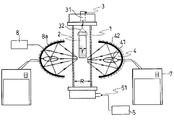
本発明に係る光加熱による被処理廃棄物の溶融無害化処理装置は、まず、図1に示すように、棒状被処理廃棄物2の成型に必要な押出成型装置を備えた成型装置(図示省略)と、成型された棒状被処理廃棄物2を、筒材としての円筒管1の上部から下方へ供給する供給機構としての可動装置3と、この可動装置3により供給された棒状被処理廃棄物2を局所的に昇温する光加熱機構4とを備えている。光加熱機構4は、円筒管1の周囲に配置され、赤外線を含む熱線を放射する光源41、および、この光源41から発せられた熱線を反射する反射鏡42を有し、光源41が、電力を供給する電源、および、この電源から供給する電力の強弱を調整する制御機構を備えた制御装置7に接続されている。なお、円筒管1は、石英からなる石英管を用いている。
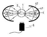
また、本発明に係る光加熱による被処理廃棄物の溶融無害化処理装置は、円筒管1の下端部の接続部51に接続される気体排出機構または気体吸入機構としての、例えば、ガス発生装置5を備え、さらに、図2に示すように、円筒管1および光加熱機構4の外側に、光加熱機構4によって棒状被処理廃棄物2の局所的に加熱された部分、および、円筒管1の壁表面部分を赤外線領域の波長で直接観察することが可能な撮影機構としての撮影装置6を備えている。
成型装置(図示省略)は、例えば、被処理廃棄物およびこの被処理廃棄物に添加される固形化材、燃焼補助材、融点低下材をはじめとする添加材が投入される回収ホッパーと、被処理廃棄物および添加材を混合して搬送する搬送管と、混合された被処理廃棄物および添加材を押し出す押出装置と、この押出装置から押し出された被処理廃棄物および添加材を成型する成型型枠とから構成される押出成型装置であり、成型型枠により、混合された被処理廃棄物および添加材を棒状被処理廃棄物2に成型するものである。
可動装置3は、成型された棒状被処理廃棄物2を円筒管1内の上部から下方へ供給するもので、モーター(図示省略)を内蔵するとともに、回転運動を直線運動に置き換える運動置換機構31、および、これに連動して棒状被処理廃棄物2を鉛直方向に吊す吊し部材32を備えている。
光加熱機構4は、上記の通り、円筒管1の周囲に配置され、可動装置3により供給された棒状被処理廃棄物2を局所的に昇温して溶融するもので、赤外線を含む熱線を放射する光源41、および、この光源41から発せられた熱線を反射する反射鏡42を有している。光源41には、例えば、ハロゲンランプを用いればよく、反射鏡42には、例えば、金メッキされた回転楕円面を持つ鏡体を用いればよい。また、図1および図2に示すように、反射鏡42は、焦点に対し左右に配置して用いられ、棒状被処理廃棄物2の局所に光源41の光を集光させている。
さらに、光源41および反射鏡42は、これらを冷却するための冷媒8aに接続され、この冷媒8aによって吸収された排熱は、熱交換機8を通じて、棒状被処理廃棄物2の成形に必要な高温を得るための熱源に使用され、或いは、ガス発生装置5により作られる空気流を昇温するための熱源に使用される。
気体排出機構または気体吸入機構としてのガス発生装置5は、円筒管1の下端部の接続部51に接続され、周囲の空気を吸入し、円筒管1内へ空気を排出することにより、円筒管1内を下部から上部へ流量20リットル/分以上で空気を流し、円筒管1内の空気流を作りだしている。なお、本実施例でガス発生装置5として例示して説明する気体排出機構または気体吸入機構は、円筒管1の下端部に接続することができ、かつ、流量20リットル/分以上で空気流を作り出せるものであれば、公知のものを使用すればよい。
撮影装置6は、円筒管1および光加熱機構4の外側に、光加熱機構4によって棒状被処理廃棄物2の局所的に加熱された部分、および、円筒管1の壁表面部分を赤外線領域の波長で直接観察することが可能なもので、例えば、NDフィルタまたはサングラスが撮像部前面に配置されたカラーCCDビデオカメラを用いればよい。
制御装置7は、上記の通り、光源41への印加電力を供給する電源を備えるとともに、光の強弱を調整するため印加電力を調整する制御装置であるほか、撮影装置6から得られる棒状被処理廃棄物2の局所的に昇温させられた部分の状態、円筒管1の壁表面の状態の評価から、円筒管1を流れる空気流の流量、棒状被処理廃棄物2の供給速度を制御する制御機能を備えた制御装置である。例えば、上記評価から光加熱機構4の光源41への印加する電力を変化させて光の強弱を調整し、円筒管1を流れる空気流の流量を、上記評価から流量20リットル/分以上の条件の下、ガス発生装置5に印可する電力を調整することにより変化させ、また、棒状被処理廃棄物2の供給速度を、上記評価から供給装置3のモーターや回転運動を直線運動に置き換える運動置換機構31へ印可する電力を調整することにより変化させることにより、それぞれ制御機能が発揮される。
なお、上記光加熱による被処理廃棄物の溶融無害化処理装置は、予め、円筒管1の内径Rと成型型枠にて成型される棒状被処理廃棄物2の外径rとの関係が、R/r≧1.8となるように構成され、棒状被処理廃棄物2の光加熱にて発生する様々な揮発成分によって円筒管1の内壁が汚れることを防いでいる。
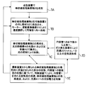
以下、本発明に係る光加熱による被処理廃棄物の溶融無害化処理装置を用いた溶融無害化処理方法(工程)を、図3に基づいて説明する。
まず、成型工程1Aでは、成型装置で棒状被処理廃棄物2を成型する。
さらに、供給工程1Bでは、例えば、ロボットにより、成型された棒状被処理廃棄物2を、可動装置3の吊し部材32に係合させ、続いて、可動装置3のモーターおよび回転運動を直線運動に置き換える運動置換機構31により速度調節可能にして、赤外線を含む光に対してエネルギー吸収が少ない円筒管1内へ供給する。
光加熱工程1Cでは、円筒管11内へ供給された棒状の被処理廃棄物2a、特にその局所を、光加熱機構4の光源41および反射鏡42による集光した光の照射により加熱する。加熱させられた棒状被処理廃棄物2は、自身の融点に達すると自ら溶融して液状化する。なお、光加熱工程1Dにおいては、円筒管1の下端部の接続部51にガス発生装置5を接続し、円筒管1内を下部から上部へ流量20リットル/分以上で空気を流す(空気流形成工程1D)。
また、観察評価工程1Eでは、円筒管1および光加熱機構4の外側に配置された撮影装置6から得られる棒状被処理廃棄物2の局所的に昇温させられた部分の状態、円筒管1の壁表面の状態を観察し、制御装置7により、光加熱工程1Dにおいて所望の溶融無害化処理が実行されているかどうかを評価し、さらに、所望の溶融無害化処理を実行するために、円筒管1を流れる空気流の流量、棒状被処理廃棄物2の供給速度、および、光源41への印加電力を制御する。制御装置による制御を受け、供給工程1B、光加熱工程1C、空気流形成工程1Dでは、その制御が反映された各工程が進められる。
ここで、本発明に係る光加熱による被処理廃棄物の溶融無害化処理装置において、棒状被処理廃棄物2を加熱する実験を行った。その結果を下記表1にて示す。
なお、実験条件としては、光加熱機構4に印加する電力、棒状被処理廃棄物2の外径r、気体排出機構を用いて流れる空気の流量を変えて行った。その他、円筒管1の内径は50mmのものを採用し、棒状被処理廃棄物2には、ロックウールとセメントと吸水性ポリマーとを、ロックウールの重量を100重量部とした場合に、セメント25重量部、吸水性ポリマー1重量部の割合で混合したものを棒状の成型型枠に流し込んで成型したものを用いた。実験では、アスベスト含有の棒状被処理廃棄物2は、安全性の理由から採用していない。また、代表的な棒状被処理廃棄物2の形状は、長さ100mm、外径18mmの円筒形を想定している。
光加熱の方法としては、棒状被処理廃棄物2の下端に焦点を合わせて光加熱を開始する方法、棒状被処理廃棄物2を下方の焦点付近の加熱帯に向かって下降させる方法などが想定され、下記表1の例では、棒状被処理廃棄物の下端に焦点を合わせて加熱を開始する方法を採用した。
光加熱の方法としては、棒状被処理廃棄物2の下端に焦点を合わせて光加熱を開始する方法、棒状被処理廃棄物2を下方の焦点付近の加熱帯に向かって下降させる方法などが想定され、下記表1の例では、棒状被処理廃棄物の下端に焦点を合わせて加熱を開始する方法を採用した。
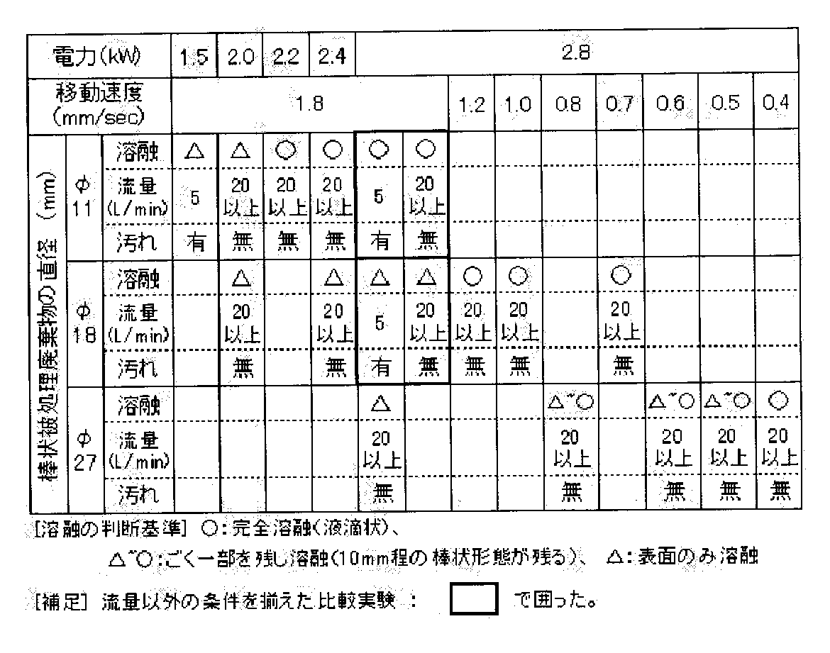
表1より、流量毎分20リットル以上で、円筒管1の内径Rと棒状被処理廃棄物2の外径rとの関係がR/r≧1.8となれば、円筒管1の内壁が汚れない状態で、完全に棒状被処理廃棄物2を溶融できることが示された。なお、R/rは理論的に、上限を特に設けるものではないが、工事現場等でのスペース、押出成型装置の大きさなどに鑑みれば、本発明に係る光加熱による被処理廃棄物の溶融無害化処理装置全体が巨大化しない範囲とすることが好ましい。
したがって、本発明に係る光加熱による被処理廃棄物の溶融無害化処理装置およびこれを用いた溶融無害化処理方法では、1000℃以下で構造的に安定で、赤外線を含む熱線に対してエネルギー吸収が少ない材料からなる石英の円筒管1を、鉛直方向に対して平行に配置し、この円筒管1の上部から下方に、制御装置7で可動装置3の供給速度を制御しながら棒状被処理廃棄物2を供給し、制御装置7で光源41への印加電力を制御しながら、光加熱機構4の光源41および反射鏡42により集光して棒状被処理廃棄物2を局所的に昇温して溶融し、円筒管1内の下部から上部へ、制御装置7で20リットル/分以上の条件下にて流量を制御しながら、ガス発生装置5により空気を流して空気流を作るとともに、その制御装置7による制御が、棒状被処理廃棄物2の局所的に昇温させられた部分、および、円筒管1の壁表面を円筒管1や光加熱機構4の外側から撮影装置6により赤外線領域の波長で直接観察して得られた結果に基づいて評価して行ったので、棒状被処理廃棄物2の正確な集光位置の制御をすることが可能になるほか、円筒管1内壁への揮発成分の付着を防止することができ、光源41からの光を円筒管1内部へ長時間継続的に通過させることが可能となって、効率よく、安全かつ確実に被処理廃棄物を溶融無害化処理することができる。
そして、円筒管1の内径Rと棒状被処理廃棄物2の外径rとを、R/r≧1.8の条件式を具備するようにして構成し、上記効果に加え、棒状被処理廃棄物2の溶融処理過程にて発生する様々な揮発成分によって円筒管1の内壁が汚れることを効果的に防ぐことができ、光源41からの光を円筒管1内部へ長時間継続的に通過させることが可能となって、光加熱による被処理廃棄物の溶融無害化処理を確実に長時間継続的に実行し、被処理廃棄物を溶融無害化処理することができる。
また、光源41および反射鏡42を冷却するための冷媒8aと、この冷媒8aに吸収された排熱を、熱交換機8を用いて棒状被処理廃棄物2の成形に必要な高温を得るための熱源に使用する、或いは、ガス発生装置5により作られる空気流を昇温するための熱源に使用したので、本発明に係る光加熱による被処理廃棄物の溶融無害化処理装置は、熱や電力の効率的な活用が可能になって、省エネ、さらには、ランニングコストの低減など市場の要請にも応えることが可能となる。
なお、本発明は、上記実施形態に限定されるものではない。そして、本発明は、請求の範囲に記載された事項を逸脱することがなければ、種々の設計変更を行うことが可能である。また、本発明は、請求の範囲に記載された事項を逸脱しなければ、システムを変更することも可能であり、本発明を構成する要素についても、公知または周知のものを使用できることはいうまでもない。
例えば、上記説明では、棒状被処理廃棄物としてのアスベスト含有物を想定した実施形態を例示したが、被処理廃棄物は、アスベスト含有物に限定されるものではない。さらに例えば、上記説明では、筒材を円筒管として例示したが、円筒管の内径Rと棒状被処理廃棄物の外径rとを、R/r≧1.8の条件式を具備するために容易な形状として例示したものであり、棒状被処理廃棄物の溶融処理過程にて発生する様々な揮発成分によって筒材の内壁が汚れることを効果的に防ぐことができるものである限り、断面形状が円形状である必要は必ずしもないものである。
本発明により、工事現場などでアスベスト等の被処理廃棄物の除去工事を行った際に、これまで厳重な袋詰め作業をして搬出していたアスベスト等の被処理廃棄物を一般廃棄物として搬出することができ、廃棄処理に要する工事費用を削減でき、廃棄物が減容化されるので、工事現場から排出される廃棄物量を削減でき、アスベスト等の被処理廃棄物の除去工事に要する工事期間も短縮できる。特に、長時間継続的に効率よく、さらに安全かつ確実に被処理廃棄物を溶融無害化することができる。なお、本発明に係る光加熱による被処理廃棄物の溶融無害化処理装置内からアスベスト粉塵が排出されることもなく、大気拡散など環境への影響も微小なものになる。
1・・円筒管(筒材)
2・・棒状被処理廃棄物
3・・可動装置(供給機構)
31・運動置換機構
32・吊り部材
4・・光加熱機構
41・光源
42・反射鏡
5・・ガス発生装置(気体排出機構または気体吸入機構)
51・接続部
6・・撮影装置(撮影機構)
7・・制御装置
8・・熱交換機
8a・冷媒
1A・成型工程
1B・供給工程
1C・光加熱工程
1D・空気流形成工程
1E・観察評価工程
R・・円筒管の内径
r・・棒状被処理廃棄物の外径
2・・棒状被処理廃棄物
3・・可動装置(供給機構)
31・運動置換機構
32・吊り部材
4・・光加熱機構
41・光源
42・反射鏡
5・・ガス発生装置(気体排出機構または気体吸入機構)
51・接続部
6・・撮影装置(撮影機構)
7・・制御装置
8・・熱交換機
8a・冷媒
1A・成型工程
1B・供給工程
1C・光加熱工程
1D・空気流形成工程
1E・観察評価工程
R・・円筒管の内径
r・・棒状被処理廃棄物の外径
Claims (5)
- 1000℃以下で構造的に安定で、赤外線を含む熱線に対してエネルギー吸収が少ない材料からなり、鉛直方向に対して平行に配置される筒材と、
この筒材の上部から下方に、棒状被処理廃棄物を供給する供給機構と、
前記筒材の周囲に配置され、赤外線を含む熱線を放射する光源およびこの光源から発せられた熱線を反射する反射鏡を有し、前記筒材内に供給される前記棒状被処理廃棄物を局所的に昇温する光加熱機構と、
この光加熱機構によって前記棒状被処理廃棄物の局所的に昇温させられた部分を、前記筒材および前記光加熱機構の外側から赤外線領域の波長で直接観察する観察機構と、
周囲の空気を吸入または前記筒材内へ空気を排出することにより、前記筒材内を下部から上部へ、流量20リットル/分以上で流れる空気流を作る気体排出機構または気体吸入機構と、
を備えることを特徴とする光加熱による被処理廃棄物の溶融無害化処理装置。 - 下記の条件式を具備することを特徴とする請求項1に記載の光加熱による被処理廃棄物の溶融無害化処理装置。
(1) R/r≧1.8
但し、R:筒材の内径
r:棒状被処理廃棄物の外径 - 前記光源および前記反射鏡を冷却するための冷媒と、
この冷媒に吸収された排熱を、前記棒状被処理廃棄物の成形に必要な高温を得るための熱源に使用する、或いは、前記気体排出機構または前記気体吸入機構により作られる空気流を昇温するための熱源に使用する熱交換機と、
を備えることを特徴とする請求項1または請求項2に記載の光加熱による被処理廃棄物の溶融無害化処理装置。 - 前記観察機構から得られる前記棒状被処理廃棄物の局所的に昇温させられた部分の状態と前記筒材の壁表面の状態とを観察し、評価して、前記筒材内を流れる前記空気流の流量、前記棒状被処理廃棄物の供給速度、前記光加熱機構の前記光源に印加する電力を制御する制御装置を備える、
ことを特徴とする請求項1から請求項3のいずれか1つに記載の光加熱による被処理廃棄物の溶融無害化処理装置。 - 請求項1から請求項4のいずれか1つに記載の光加熱による被処理廃棄物の溶融無害化処理装置を用いる、
ことを特徴とする光加熱による被処理廃棄物の溶融無害化処理方法。
Applications Claiming Priority (2)
| Application Number | Priority Date | Filing Date | Title |
|---|---|---|---|
| JP2009078370A JP4863316B2 (ja) | 2009-03-27 | 2009-03-27 | 光加熱による被処理廃棄物の溶融無害化処理装置およびこれを用いた溶融無害化処理方法。 |
| JP2009-078370 | 2009-03-27 |
Publications (1)
| Publication Number | Publication Date |
|---|---|
| WO2010110195A1 true WO2010110195A1 (ja) | 2010-09-30 |
Family
ID=42780889
Family Applications (1)
| Application Number | Title | Priority Date | Filing Date |
|---|---|---|---|
| PCT/JP2010/054762 Ceased WO2010110195A1 (ja) | 2009-03-27 | 2010-03-19 | 光加熱による廃棄物の溶融装置及び方法 |
Country Status (2)
| Country | Link |
|---|---|
| JP (1) | JP4863316B2 (ja) |
| WO (1) | WO2010110195A1 (ja) |
Families Citing this family (2)
| Publication number | Priority date | Publication date | Assignee | Title |
|---|---|---|---|---|
| JP5754773B2 (ja) * | 2011-05-09 | 2015-07-29 | 国立研究開発法人産業技術総合研究所 | 加熱用容器、局所加熱装置および加熱方法 |
| KR101647603B1 (ko) * | 2015-11-04 | 2016-08-10 | 김수용 | 근적외선 복사열을 이용한 석면물질 무해화 처리장치 |
Citations (6)
| Publication number | Priority date | Publication date | Assignee | Title |
|---|---|---|---|---|
| JPH02275800A (ja) * | 1988-12-29 | 1990-11-09 | Hironao Kojima | 超伝導酸化物の単結晶及びその製造方法 |
| JPH10141642A (ja) * | 1996-11-13 | 1998-05-29 | Komatsu Ltd | 廃棄物の溶融方法及びその装置 |
| JPH10507275A (ja) * | 1995-07-26 | 1998-07-14 | ブリティッシュ・ニュークリア・フューエルズ・パブリック・リミテッド・カンパニー | 廃棄物処理方法および同処理装置 |
| JP2002327217A (ja) * | 2001-05-02 | 2002-11-15 | Furukawa Co Ltd | 有価金属の回収方法 |
| WO2008072467A1 (ja) * | 2006-12-15 | 2008-06-19 | National Institute Of Advanced Industrial Science And Technology | アスベストの溶融方法及びそのための装置 |
| JP2010005541A (ja) * | 2008-06-27 | 2010-01-14 | National Institute Of Advanced Industrial & Technology | 被処理廃棄物の溶融無害化処理装置 |
-
2009
- 2009-03-27 JP JP2009078370A patent/JP4863316B2/ja not_active Expired - Fee Related
-
2010
- 2010-03-19 WO PCT/JP2010/054762 patent/WO2010110195A1/ja not_active Ceased
Patent Citations (6)
| Publication number | Priority date | Publication date | Assignee | Title |
|---|---|---|---|---|
| JPH02275800A (ja) * | 1988-12-29 | 1990-11-09 | Hironao Kojima | 超伝導酸化物の単結晶及びその製造方法 |
| JPH10507275A (ja) * | 1995-07-26 | 1998-07-14 | ブリティッシュ・ニュークリア・フューエルズ・パブリック・リミテッド・カンパニー | 廃棄物処理方法および同処理装置 |
| JPH10141642A (ja) * | 1996-11-13 | 1998-05-29 | Komatsu Ltd | 廃棄物の溶融方法及びその装置 |
| JP2002327217A (ja) * | 2001-05-02 | 2002-11-15 | Furukawa Co Ltd | 有価金属の回収方法 |
| WO2008072467A1 (ja) * | 2006-12-15 | 2008-06-19 | National Institute Of Advanced Industrial Science And Technology | アスベストの溶融方法及びそのための装置 |
| JP2010005541A (ja) * | 2008-06-27 | 2010-01-14 | National Institute Of Advanced Industrial & Technology | 被処理廃棄物の溶融無害化処理装置 |
Also Published As
| Publication number | Publication date |
|---|---|
| JP4863316B2 (ja) | 2012-01-25 |
| JP2010227828A (ja) | 2010-10-14 |
Similar Documents
| Publication | Publication Date | Title |
|---|---|---|
| JP7078603B2 (ja) | 立体自由形状造形法のための多室型堆積設備 | |
| US8197768B2 (en) | Apparatus for conversion of materials including asbestos | |
| JP2007529711A (ja) | 廃棄物を処理するための方法および装置 | |
| CN110434502A (zh) | 一种基于激光清洗的6系铝合金型材焊接装置及方法 | |
| CN104070053B (zh) | 一种垃圾焚烧飞灰分级煅烧减量化处理技术 | |
| JP4833093B2 (ja) | ごみ焼却飛灰処理方法 | |
| CN108826302B (zh) | 医疗废弃物无害化处理设备 | |
| JP4863316B2 (ja) | 光加熱による被処理廃棄物の溶融無害化処理装置およびこれを用いた溶融無害化処理方法。 | |
| JPH10507275A (ja) | 廃棄物処理方法および同処理装置 | |
| HU210792B (en) | Process and furnace for treating meltable waste products | |
| JP2008183497A (ja) | 粉塵の処理方法、及び粉塵の処理装置 | |
| WO2008072467A1 (ja) | アスベストの溶融方法及びそのための装置 | |
| US7802451B2 (en) | Manufacturing device for producing mineral fibers from incinerator ashes and its plasma-vitrified slag | |
| JP7666614B2 (ja) | 処理装置および方法 | |
| JP2007301425A (ja) | アスベスト含有廃棄物溶融装置 | |
| JPH11114531A (ja) | 廃棄プラスチック処理装置 | |
| CN103752583B (zh) | 卤代POPs废物处理系统 | |
| JP4675804B2 (ja) | ポリ塩化ビフェニル汚染物の処理設備 | |
| KR101647603B1 (ko) | 근적외선 복사열을 이용한 석면물질 무해화 처리장치 | |
| RS59261B1 (sr) | Postupak recikliranja otpadnog čelika koji sadrži azbest | |
| JP4986822B2 (ja) | ガスの化学的乾式処理方法 | |
| CN215766507U (zh) | 等离子体炉连续排渣装置 | |
| JP5355882B2 (ja) | 分解処理装置の反応管封止装置及び分解処理装置の反応管封止装置の使用方法 | |
| JP5754773B2 (ja) | 加熱用容器、局所加熱装置および加熱方法 | |
| JP4711310B2 (ja) | 石綿含有廃材の処理方法 |
Legal Events
| Date | Code | Title | Description |
|---|---|---|---|
| 121 | Ep: the epo has been informed by wipo that ep was designated in this application |
Ref document number: 10755992 Country of ref document: EP Kind code of ref document: A1 |
|
| NENP | Non-entry into the national phase |
Ref country code: DE |
|
| 122 | Ep: pct application non-entry in european phase |
Ref document number: 10755992 Country of ref document: EP Kind code of ref document: A1 |