WO2010104077A1 - Laminated separator, polyolefin micro-porous membrane, and separator for electricity storage device - Google Patents
Laminated separator, polyolefin micro-porous membrane, and separator for electricity storage device Download PDFInfo
- Publication number
- WO2010104077A1 WO2010104077A1 PCT/JP2010/053899 JP2010053899W WO2010104077A1 WO 2010104077 A1 WO2010104077 A1 WO 2010104077A1 JP 2010053899 W JP2010053899 W JP 2010053899W WO 2010104077 A1 WO2010104077 A1 WO 2010104077A1
- Authority
- WO
- WIPO (PCT)
- Prior art keywords
- mass
- polyolefin
- microporous membrane
- less
- polypropylene
- Prior art date
Links
Images

Classifications
-
- H—ELECTRICITY
- H01—ELECTRIC ELEMENTS
- H01M—PROCESSES OR MEANS, e.g. BATTERIES, FOR THE DIRECT CONVERSION OF CHEMICAL ENERGY INTO ELECTRICAL ENERGY
- H01M50/00—Constructional details or processes of manufacture of the non-active parts of electrochemical cells other than fuel cells, e.g. hybrid cells
- H01M50/40—Separators; Membranes; Diaphragms; Spacing elements inside cells
- H01M50/489—Separators, membranes, diaphragms or spacing elements inside the cells, characterised by their physical properties, e.g. swelling degree, hydrophilicity or shut down properties
- H01M50/491—Porosity
-
- C—CHEMISTRY; METALLURGY
- C08—ORGANIC MACROMOLECULAR COMPOUNDS; THEIR PREPARATION OR CHEMICAL WORKING-UP; COMPOSITIONS BASED THEREON
- C08L—COMPOSITIONS OF MACROMOLECULAR COMPOUNDS
- C08L23/00—Compositions of homopolymers or copolymers of unsaturated aliphatic hydrocarbons having only one carbon-to-carbon double bond; Compositions of derivatives of such polymers
- C08L23/02—Compositions of homopolymers or copolymers of unsaturated aliphatic hydrocarbons having only one carbon-to-carbon double bond; Compositions of derivatives of such polymers not modified by chemical after-treatment
- C08L23/10—Homopolymers or copolymers of propene
- C08L23/12—Polypropene
-
- B—PERFORMING OPERATIONS; TRANSPORTING
- B32—LAYERED PRODUCTS
- B32B—LAYERED PRODUCTS, i.e. PRODUCTS BUILT-UP OF STRATA OF FLAT OR NON-FLAT, e.g. CELLULAR OR HONEYCOMB, FORM
- B32B27/00—Layered products comprising a layer of synthetic resin
- B32B27/06—Layered products comprising a layer of synthetic resin as the main or only constituent of a layer, which is next to another layer of the same or of a different material
- B32B27/08—Layered products comprising a layer of synthetic resin as the main or only constituent of a layer, which is next to another layer of the same or of a different material of synthetic resin
-
- B—PERFORMING OPERATIONS; TRANSPORTING
- B29—WORKING OF PLASTICS; WORKING OF SUBSTANCES IN A PLASTIC STATE IN GENERAL
- B29C—SHAPING OR JOINING OF PLASTICS; SHAPING OF MATERIAL IN A PLASTIC STATE, NOT OTHERWISE PROVIDED FOR; AFTER-TREATMENT OF THE SHAPED PRODUCTS, e.g. REPAIRING
- B29C48/00—Extrusion moulding, i.e. expressing the moulding material through a die or nozzle which imparts the desired form; Apparatus therefor
- B29C48/001—Combinations of extrusion moulding with other shaping operations
- B29C48/0018—Combinations of extrusion moulding with other shaping operations combined with shaping by orienting, stretching or shrinking, e.g. film blowing
-
- B—PERFORMING OPERATIONS; TRANSPORTING
- B29—WORKING OF PLASTICS; WORKING OF SUBSTANCES IN A PLASTIC STATE IN GENERAL
- B29C—SHAPING OR JOINING OF PLASTICS; SHAPING OF MATERIAL IN A PLASTIC STATE, NOT OTHERWISE PROVIDED FOR; AFTER-TREATMENT OF THE SHAPED PRODUCTS, e.g. REPAIRING
- B29C55/00—Shaping by stretching, e.g. drawing through a die; Apparatus therefor
- B29C55/02—Shaping by stretching, e.g. drawing through a die; Apparatus therefor of plates or sheets
- B29C55/10—Shaping by stretching, e.g. drawing through a die; Apparatus therefor of plates or sheets multiaxial
- B29C55/12—Shaping by stretching, e.g. drawing through a die; Apparatus therefor of plates or sheets multiaxial biaxial
-
- B—PERFORMING OPERATIONS; TRANSPORTING
- B29—WORKING OF PLASTICS; WORKING OF SUBSTANCES IN A PLASTIC STATE IN GENERAL
- B29C—SHAPING OR JOINING OF PLASTICS; SHAPING OF MATERIAL IN A PLASTIC STATE, NOT OTHERWISE PROVIDED FOR; AFTER-TREATMENT OF THE SHAPED PRODUCTS, e.g. REPAIRING
- B29C67/00—Shaping techniques not covered by groups B29C39/00 - B29C65/00, B29C70/00 or B29C73/00
- B29C67/20—Shaping techniques not covered by groups B29C39/00 - B29C65/00, B29C70/00 or B29C73/00 for porous or cellular articles, e.g. of foam plastics, coarse-pored
- B29C67/202—Shaping techniques not covered by groups B29C39/00 - B29C65/00, B29C70/00 or B29C73/00 for porous or cellular articles, e.g. of foam plastics, coarse-pored comprising elimination of a solid or a liquid ingredient
-
- B—PERFORMING OPERATIONS; TRANSPORTING
- B32—LAYERED PRODUCTS
- B32B—LAYERED PRODUCTS, i.e. PRODUCTS BUILT-UP OF STRATA OF FLAT OR NON-FLAT, e.g. CELLULAR OR HONEYCOMB, FORM
- B32B27/00—Layered products comprising a layer of synthetic resin
- B32B27/18—Layered products comprising a layer of synthetic resin characterised by the use of special additives
- B32B27/20—Layered products comprising a layer of synthetic resin characterised by the use of special additives using fillers, pigments, thixotroping agents
- B32B27/205—Layered products comprising a layer of synthetic resin characterised by the use of special additives using fillers, pigments, thixotroping agents the fillers creating voids or cavities, e.g. by stretching
-
- B—PERFORMING OPERATIONS; TRANSPORTING
- B32—LAYERED PRODUCTS
- B32B—LAYERED PRODUCTS, i.e. PRODUCTS BUILT-UP OF STRATA OF FLAT OR NON-FLAT, e.g. CELLULAR OR HONEYCOMB, FORM
- B32B27/00—Layered products comprising a layer of synthetic resin
- B32B27/32—Layered products comprising a layer of synthetic resin comprising polyolefins
-
- B—PERFORMING OPERATIONS; TRANSPORTING
- B32—LAYERED PRODUCTS
- B32B—LAYERED PRODUCTS, i.e. PRODUCTS BUILT-UP OF STRATA OF FLAT OR NON-FLAT, e.g. CELLULAR OR HONEYCOMB, FORM
- B32B3/00—Layered products comprising a layer with external or internal discontinuities or unevennesses, or a layer of non-planar form; Layered products having particular features of form
- B32B3/26—Layered products comprising a layer with external or internal discontinuities or unevennesses, or a layer of non-planar form; Layered products having particular features of form characterised by a particular shape of the outline of the cross-section of a continuous layer; characterised by a layer with cavities or internal voids ; characterised by an apertured layer
- B32B3/266—Layered products comprising a layer with external or internal discontinuities or unevennesses, or a layer of non-planar form; Layered products having particular features of form characterised by a particular shape of the outline of the cross-section of a continuous layer; characterised by a layer with cavities or internal voids ; characterised by an apertured layer characterised by an apertured layer, the apertures going through the whole thickness of the layer, e.g. expanded metal, perforated layer, slit layer regular cells B32B3/12
-
- B—PERFORMING OPERATIONS; TRANSPORTING
- B32—LAYERED PRODUCTS
- B32B—LAYERED PRODUCTS, i.e. PRODUCTS BUILT-UP OF STRATA OF FLAT OR NON-FLAT, e.g. CELLULAR OR HONEYCOMB, FORM
- B32B5/00—Layered products characterised by the non- homogeneity or physical structure, i.e. comprising a fibrous, filamentary, particulate or foam layer; Layered products characterised by having a layer differing constitutionally or physically in different parts
- B32B5/22—Layered products characterised by the non- homogeneity or physical structure, i.e. comprising a fibrous, filamentary, particulate or foam layer; Layered products characterised by having a layer differing constitutionally or physically in different parts characterised by the presence of two or more layers which are next to each other and are fibrous, filamentary, formed of particles or foamed
-
- C—CHEMISTRY; METALLURGY
- C08—ORGANIC MACROMOLECULAR COMPOUNDS; THEIR PREPARATION OR CHEMICAL WORKING-UP; COMPOSITIONS BASED THEREON
- C08L—COMPOSITIONS OF MACROMOLECULAR COMPOUNDS
- C08L23/00—Compositions of homopolymers or copolymers of unsaturated aliphatic hydrocarbons having only one carbon-to-carbon double bond; Compositions of derivatives of such polymers
- C08L23/02—Compositions of homopolymers or copolymers of unsaturated aliphatic hydrocarbons having only one carbon-to-carbon double bond; Compositions of derivatives of such polymers not modified by chemical after-treatment
- C08L23/04—Homopolymers or copolymers of ethene
- C08L23/06—Polyethene
-
- C—CHEMISTRY; METALLURGY
- C08—ORGANIC MACROMOLECULAR COMPOUNDS; THEIR PREPARATION OR CHEMICAL WORKING-UP; COMPOSITIONS BASED THEREON
- C08L—COMPOSITIONS OF MACROMOLECULAR COMPOUNDS
- C08L23/00—Compositions of homopolymers or copolymers of unsaturated aliphatic hydrocarbons having only one carbon-to-carbon double bond; Compositions of derivatives of such polymers
- C08L23/02—Compositions of homopolymers or copolymers of unsaturated aliphatic hydrocarbons having only one carbon-to-carbon double bond; Compositions of derivatives of such polymers not modified by chemical after-treatment
- C08L23/10—Homopolymers or copolymers of propene
- C08L23/14—Copolymers of propene
-
- H—ELECTRICITY
- H01—ELECTRIC ELEMENTS
- H01G—CAPACITORS; CAPACITORS, RECTIFIERS, DETECTORS, SWITCHING DEVICES OR LIGHT-SENSITIVE DEVICES, OF THE ELECTROLYTIC TYPE
- H01G11/00—Hybrid capacitors, i.e. capacitors having different positive and negative electrodes; Electric double-layer [EDL] capacitors; Processes for the manufacture thereof or of parts thereof
- H01G11/52—Separators
-
- H—ELECTRICITY
- H01—ELECTRIC ELEMENTS
- H01M—PROCESSES OR MEANS, e.g. BATTERIES, FOR THE DIRECT CONVERSION OF CHEMICAL ENERGY INTO ELECTRICAL ENERGY
- H01M10/00—Secondary cells; Manufacture thereof
- H01M10/05—Accumulators with non-aqueous electrolyte
- H01M10/052—Li-accumulators
- H01M10/0525—Rocking-chair batteries, i.e. batteries with lithium insertion or intercalation in both electrodes; Lithium-ion batteries
-
- H—ELECTRICITY
- H01—ELECTRIC ELEMENTS
- H01M—PROCESSES OR MEANS, e.g. BATTERIES, FOR THE DIRECT CONVERSION OF CHEMICAL ENERGY INTO ELECTRICAL ENERGY
- H01M50/00—Constructional details or processes of manufacture of the non-active parts of electrochemical cells other than fuel cells, e.g. hybrid cells
- H01M50/40—Separators; Membranes; Diaphragms; Spacing elements inside cells
- H01M50/403—Manufacturing processes of separators, membranes or diaphragms
-
- H—ELECTRICITY
- H01—ELECTRIC ELEMENTS
- H01M—PROCESSES OR MEANS, e.g. BATTERIES, FOR THE DIRECT CONVERSION OF CHEMICAL ENERGY INTO ELECTRICAL ENERGY
- H01M50/00—Constructional details or processes of manufacture of the non-active parts of electrochemical cells other than fuel cells, e.g. hybrid cells
- H01M50/40—Separators; Membranes; Diaphragms; Spacing elements inside cells
- H01M50/409—Separators, membranes or diaphragms characterised by the material
- H01M50/411—Organic material
- H01M50/414—Synthetic resins, e.g. thermoplastics or thermosetting resins
- H01M50/417—Polyolefins
-
- H—ELECTRICITY
- H01—ELECTRIC ELEMENTS
- H01M—PROCESSES OR MEANS, e.g. BATTERIES, FOR THE DIRECT CONVERSION OF CHEMICAL ENERGY INTO ELECTRICAL ENERGY
- H01M50/00—Constructional details or processes of manufacture of the non-active parts of electrochemical cells other than fuel cells, e.g. hybrid cells
- H01M50/40—Separators; Membranes; Diaphragms; Spacing elements inside cells
- H01M50/409—Separators, membranes or diaphragms characterised by the material
- H01M50/431—Inorganic material
-
- H—ELECTRICITY
- H01—ELECTRIC ELEMENTS
- H01M—PROCESSES OR MEANS, e.g. BATTERIES, FOR THE DIRECT CONVERSION OF CHEMICAL ENERGY INTO ELECTRICAL ENERGY
- H01M50/00—Constructional details or processes of manufacture of the non-active parts of electrochemical cells other than fuel cells, e.g. hybrid cells
- H01M50/40—Separators; Membranes; Diaphragms; Spacing elements inside cells
- H01M50/409—Separators, membranes or diaphragms characterised by the material
- H01M50/443—Particulate material
-
- H—ELECTRICITY
- H01—ELECTRIC ELEMENTS
- H01M—PROCESSES OR MEANS, e.g. BATTERIES, FOR THE DIRECT CONVERSION OF CHEMICAL ENERGY INTO ELECTRICAL ENERGY
- H01M50/00—Constructional details or processes of manufacture of the non-active parts of electrochemical cells other than fuel cells, e.g. hybrid cells
- H01M50/40—Separators; Membranes; Diaphragms; Spacing elements inside cells
- H01M50/409—Separators, membranes or diaphragms characterised by the material
- H01M50/446—Composite material consisting of a mixture of organic and inorganic materials
-
- H—ELECTRICITY
- H01—ELECTRIC ELEMENTS
- H01M—PROCESSES OR MEANS, e.g. BATTERIES, FOR THE DIRECT CONVERSION OF CHEMICAL ENERGY INTO ELECTRICAL ENERGY
- H01M50/00—Constructional details or processes of manufacture of the non-active parts of electrochemical cells other than fuel cells, e.g. hybrid cells
- H01M50/40—Separators; Membranes; Diaphragms; Spacing elements inside cells
- H01M50/409—Separators, membranes or diaphragms characterised by the material
- H01M50/449—Separators, membranes or diaphragms characterised by the material having a layered structure
- H01M50/451—Separators, membranes or diaphragms characterised by the material having a layered structure comprising layers of only organic material and layers containing inorganic material
-
- H—ELECTRICITY
- H01—ELECTRIC ELEMENTS
- H01M—PROCESSES OR MEANS, e.g. BATTERIES, FOR THE DIRECT CONVERSION OF CHEMICAL ENERGY INTO ELECTRICAL ENERGY
- H01M50/00—Constructional details or processes of manufacture of the non-active parts of electrochemical cells other than fuel cells, e.g. hybrid cells
- H01M50/40—Separators; Membranes; Diaphragms; Spacing elements inside cells
- H01M50/409—Separators, membranes or diaphragms characterised by the material
- H01M50/449—Separators, membranes or diaphragms characterised by the material having a layered structure
- H01M50/457—Separators, membranes or diaphragms characterised by the material having a layered structure comprising three or more layers
-
- H—ELECTRICITY
- H01—ELECTRIC ELEMENTS
- H01M—PROCESSES OR MEANS, e.g. BATTERIES, FOR THE DIRECT CONVERSION OF CHEMICAL ENERGY INTO ELECTRICAL ENERGY
- H01M50/00—Constructional details or processes of manufacture of the non-active parts of electrochemical cells other than fuel cells, e.g. hybrid cells
- H01M50/40—Separators; Membranes; Diaphragms; Spacing elements inside cells
- H01M50/489—Separators, membranes, diaphragms or spacing elements inside the cells, characterised by their physical properties, e.g. swelling degree, hydrophilicity or shut down properties
-
- B—PERFORMING OPERATIONS; TRANSPORTING
- B29—WORKING OF PLASTICS; WORKING OF SUBSTANCES IN A PLASTIC STATE IN GENERAL
- B29K—INDEXING SCHEME ASSOCIATED WITH SUBCLASSES B29B, B29C OR B29D, RELATING TO MOULDING MATERIALS OR TO MATERIALS FOR MOULDS, REINFORCEMENTS, FILLERS OR PREFORMED PARTS, e.g. INSERTS
- B29K2023/00—Use of polyalkenes or derivatives thereof as moulding material
- B29K2023/04—Polymers of ethylene
- B29K2023/06—PE, i.e. polyethylene
-
- B—PERFORMING OPERATIONS; TRANSPORTING
- B29—WORKING OF PLASTICS; WORKING OF SUBSTANCES IN A PLASTIC STATE IN GENERAL
- B29K—INDEXING SCHEME ASSOCIATED WITH SUBCLASSES B29B, B29C OR B29D, RELATING TO MOULDING MATERIALS OR TO MATERIALS FOR MOULDS, REINFORCEMENTS, FILLERS OR PREFORMED PARTS, e.g. INSERTS
- B29K2023/00—Use of polyalkenes or derivatives thereof as moulding material
- B29K2023/10—Polymers of propylene
- B29K2023/12—PP, i.e. polypropylene
-
- B—PERFORMING OPERATIONS; TRANSPORTING
- B29—WORKING OF PLASTICS; WORKING OF SUBSTANCES IN A PLASTIC STATE IN GENERAL
- B29L—INDEXING SCHEME ASSOCIATED WITH SUBCLASS B29C, RELATING TO PARTICULAR ARTICLES
- B29L2031/00—Other particular articles
- B29L2031/755—Membranes, diaphragms
-
- B—PERFORMING OPERATIONS; TRANSPORTING
- B32—LAYERED PRODUCTS
- B32B—LAYERED PRODUCTS, i.e. PRODUCTS BUILT-UP OF STRATA OF FLAT OR NON-FLAT, e.g. CELLULAR OR HONEYCOMB, FORM
- B32B2250/00—Layers arrangement
- B32B2250/03—3 layers
-
- B—PERFORMING OPERATIONS; TRANSPORTING
- B32—LAYERED PRODUCTS
- B32B—LAYERED PRODUCTS, i.e. PRODUCTS BUILT-UP OF STRATA OF FLAT OR NON-FLAT, e.g. CELLULAR OR HONEYCOMB, FORM
- B32B2250/00—Layers arrangement
- B32B2250/24—All layers being polymeric
-
- B—PERFORMING OPERATIONS; TRANSPORTING
- B32—LAYERED PRODUCTS
- B32B—LAYERED PRODUCTS, i.e. PRODUCTS BUILT-UP OF STRATA OF FLAT OR NON-FLAT, e.g. CELLULAR OR HONEYCOMB, FORM
- B32B2250/00—Layers arrangement
- B32B2250/24—All layers being polymeric
- B32B2250/242—All polymers belonging to those covered by group B32B27/32
-
- B—PERFORMING OPERATIONS; TRANSPORTING
- B32—LAYERED PRODUCTS
- B32B—LAYERED PRODUCTS, i.e. PRODUCTS BUILT-UP OF STRATA OF FLAT OR NON-FLAT, e.g. CELLULAR OR HONEYCOMB, FORM
- B32B2250/00—Layers arrangement
- B32B2250/40—Symmetrical or sandwich layers, e.g. ABA, ABCBA, ABCCBA
-
- B—PERFORMING OPERATIONS; TRANSPORTING
- B32—LAYERED PRODUCTS
- B32B—LAYERED PRODUCTS, i.e. PRODUCTS BUILT-UP OF STRATA OF FLAT OR NON-FLAT, e.g. CELLULAR OR HONEYCOMB, FORM
- B32B2264/00—Composition or properties of particles which form a particulate layer or are present as additives
- B32B2264/10—Inorganic particles
- B32B2264/102—Oxide or hydroxide
-
- B—PERFORMING OPERATIONS; TRANSPORTING
- B32—LAYERED PRODUCTS
- B32B—LAYERED PRODUCTS, i.e. PRODUCTS BUILT-UP OF STRATA OF FLAT OR NON-FLAT, e.g. CELLULAR OR HONEYCOMB, FORM
- B32B2270/00—Resin or rubber layer containing a blend of at least two different polymers
-
- B—PERFORMING OPERATIONS; TRANSPORTING
- B32—LAYERED PRODUCTS
- B32B—LAYERED PRODUCTS, i.e. PRODUCTS BUILT-UP OF STRATA OF FLAT OR NON-FLAT, e.g. CELLULAR OR HONEYCOMB, FORM
- B32B2305/00—Condition, form or state of the layers or laminate
- B32B2305/02—Cellular or porous
- B32B2305/026—Porous
-
- B—PERFORMING OPERATIONS; TRANSPORTING
- B32—LAYERED PRODUCTS
- B32B—LAYERED PRODUCTS, i.e. PRODUCTS BUILT-UP OF STRATA OF FLAT OR NON-FLAT, e.g. CELLULAR OR HONEYCOMB, FORM
- B32B2305/00—Condition, form or state of the layers or laminate
- B32B2305/30—Fillers, e.g. particles, powders, beads, flakes, spheres, chips
-
- B—PERFORMING OPERATIONS; TRANSPORTING
- B32—LAYERED PRODUCTS
- B32B—LAYERED PRODUCTS, i.e. PRODUCTS BUILT-UP OF STRATA OF FLAT OR NON-FLAT, e.g. CELLULAR OR HONEYCOMB, FORM
- B32B2307/00—Properties of the layers or laminate
- B32B2307/30—Properties of the layers or laminate having particular thermal properties
- B32B2307/306—Resistant to heat
-
- B—PERFORMING OPERATIONS; TRANSPORTING
- B32—LAYERED PRODUCTS
- B32B—LAYERED PRODUCTS, i.e. PRODUCTS BUILT-UP OF STRATA OF FLAT OR NON-FLAT, e.g. CELLULAR OR HONEYCOMB, FORM
- B32B2307/00—Properties of the layers or laminate
- B32B2307/50—Properties of the layers or laminate having particular mechanical properties
- B32B2307/514—Oriented
- B32B2307/518—Oriented bi-axially
-
- B—PERFORMING OPERATIONS; TRANSPORTING
- B32—LAYERED PRODUCTS
- B32B—LAYERED PRODUCTS, i.e. PRODUCTS BUILT-UP OF STRATA OF FLAT OR NON-FLAT, e.g. CELLULAR OR HONEYCOMB, FORM
- B32B2307/00—Properties of the layers or laminate
- B32B2307/70—Other properties
- B32B2307/724—Permeability to gases, adsorption
-
- C—CHEMISTRY; METALLURGY
- C08—ORGANIC MACROMOLECULAR COMPOUNDS; THEIR PREPARATION OR CHEMICAL WORKING-UP; COMPOSITIONS BASED THEREON
- C08L—COMPOSITIONS OF MACROMOLECULAR COMPOUNDS
- C08L2203/00—Applications
- C08L2203/16—Applications used for films
-
- H—ELECTRICITY
- H01—ELECTRIC ELEMENTS
- H01M—PROCESSES OR MEANS, e.g. BATTERIES, FOR THE DIRECT CONVERSION OF CHEMICAL ENERGY INTO ELECTRICAL ENERGY
- H01M10/00—Secondary cells; Manufacture thereof
- H01M10/05—Accumulators with non-aqueous electrolyte
- H01M10/052—Li-accumulators
-
- Y—GENERAL TAGGING OF NEW TECHNOLOGICAL DEVELOPMENTS; GENERAL TAGGING OF CROSS-SECTIONAL TECHNOLOGIES SPANNING OVER SEVERAL SECTIONS OF THE IPC; TECHNICAL SUBJECTS COVERED BY FORMER USPC CROSS-REFERENCE ART COLLECTIONS [XRACs] AND DIGESTS
- Y02—TECHNOLOGIES OR APPLICATIONS FOR MITIGATION OR ADAPTATION AGAINST CLIMATE CHANGE
- Y02E—REDUCTION OF GREENHOUSE GAS [GHG] EMISSIONS, RELATED TO ENERGY GENERATION, TRANSMISSION OR DISTRIBUTION
- Y02E60/00—Enabling technologies; Technologies with a potential or indirect contribution to GHG emissions mitigation
- Y02E60/10—Energy storage using batteries
-
- Y—GENERAL TAGGING OF NEW TECHNOLOGICAL DEVELOPMENTS; GENERAL TAGGING OF CROSS-SECTIONAL TECHNOLOGIES SPANNING OVER SEVERAL SECTIONS OF THE IPC; TECHNICAL SUBJECTS COVERED BY FORMER USPC CROSS-REFERENCE ART COLLECTIONS [XRACs] AND DIGESTS
- Y02—TECHNOLOGIES OR APPLICATIONS FOR MITIGATION OR ADAPTATION AGAINST CLIMATE CHANGE
- Y02T—CLIMATE CHANGE MITIGATION TECHNOLOGIES RELATED TO TRANSPORTATION
- Y02T10/00—Road transport of goods or passengers
- Y02T10/60—Other road transportation technologies with climate change mitigation effect
- Y02T10/70—Energy storage systems for electromobility, e.g. batteries
Definitions
- the present invention relates to a laminated separator, a polyolefin microporous membrane, a storage device separator, and the like.
- Polyolefin resin microporous membranes are used as battery separators, particularly lithium ion battery separators. Lithium ion batteries are used in small electronic devices such as mobile phones and notebook personal computers, and are also applied to electric tools, hybrid vehicles, electric vehicles, and the like. Conventionally, a polyethylene microporous membrane is used for a lithium ion battery separator. The reason is that the polyethylene microporous membrane is excellent in permeability and has the function of melting the polymer at 130 ° C to 150 ° C to close the communication hole and shutting down the current in order to ensure battery safety. is there.
- “Shutdown” is a phenomenon in which the flow of lithium ions is blocked by the pores of the microporous membrane being blocked by molten resin and increasing the electrical resistance of the membrane.
- the battery reaction is quickly stopped in the case of abnormal heating in addition to a certain mechanical property that does not break during repeated charging and discharging. Characteristics (fuse characteristics), performance that maintains the shape even at high temperatures and prevents a dangerous situation in which the positive electrode material and the negative electrode material react directly (short characteristics) are also required.
- a first object of the present invention is to provide a separator that achieves both heat resistance, shutdown characteristics, and cycle characteristics at a high level.
- a second object of the present invention is to provide a polyolefin microporous film suitable as a separator that can improve the cycle characteristics of an electricity storage device.
- the present inventor has inorganic particles whose particle diameter is within a specific range, and a laminated separator having a laminated structure has a high degree of heat resistance, shutdown characteristics, and cycle characteristics. It was found that both can be compatible.
- the second problem can be solved by blending a specific amount of a specific propylene copolymer in a polypropylene-based microporous membrane.
- the present inventors have found that the second problem can be solved by blending a specific amount of a specific propylene copolymer in a polypropylene-based microporous membrane containing an inorganic filler, thereby completing the present invention. It was.
- the present invention is as follows. [1] A polyolefin first microporous layer, and a polyolefin second microporous layer stacked on the first microporous layer and different from the first microporous layer, A laminated separator in which at least one of the first microporous layer and the second microporous layer contains inorganic particles having a primary particle diameter of 1 nm or more and 80 nm or less.
- the laminated separator according to [1] or [2], wherein the inorganic particles are one or more selected from the group consisting of silicon oxide, aluminum oxide, and titanium oxide.
- the polyolefin first microporous layer is a surface layer
- the polyolefin second microporous layer is an intermediate layer and has at least two kinds and three layers.
- the polyolefin first microporous layer contains 5 to 90% by mass of a polyolefin resin based on the total amount of the polyolefin resin and inorganic particles that are constituents of the first microporous layer
- the polyolefin second microporous layer The laminate according to any one of [1] to [3], which contains 60 to 100% by mass of a polyolefin resin based on the total amount of the polyolefin resin and inorganic particles that are constituent components of the second microporous layer. Separator.
- the polyolefin resin contains polyethylene and polypropylene, and the proportion of the polypropylene in the total amount of the polyethylene and polypropylene is 10% by mass to 95% by mass.
- Separator Formed of a polyolefin resin containing 50 to 99% by mass of polypropylene and 1 to 50% by mass of a propylene- ⁇ -olefin copolymer as a main component, A polyolefin microporous membrane having an ⁇ -olefin content in the propylene- ⁇ -olefin copolymer of more than 1% by mass and 15% by mass or less.
- a separator for an electricity storage device comprising the polyolefin microporous membrane according to any one of [10] to [11] or the laminated polyolefin microporous membrane according to [11].
- (Polypropylene) / (propylene copolymer) (mass ratio) is formed of a propylene resin composition containing as a main component a polypropylene resin having a mass ratio of 80/20 to 0/100, A polyolefin microporous membrane, wherein the propylene copolymer has a melting point of 120 ° C or higher and 145 ° C or lower.
- the propylene-based resin composition further includes high-density polyethylene, The polyolefin microporous membrane according to any one of [13] to [15], wherein the proportion of the high-density polyethylene in the propylene-based resin composition is 5 to 50% by mass.
- the propylene-based resin composition further contains an inorganic filler, The polyolefin microporous membrane according to any one of [13] to [16], wherein the proportion of the inorganic filler in the propylene resin composition is 5 to 60% by mass.
- a separator for a non-aqueous electrolyte comprising the polyolefin microporous membrane according to any one of [17] or the laminated polyolefin microporous membrane according to [18].
- the manufacturing method characterized by having. [21] [20] The production method according to [20], wherein the heat of fusion of the propylene copolymer is 60 J / g or more. [22] (Polypropylene) / (Propylene copolymer) (Mass ratio) Polypropylene resin composition comprising 20 to 95% by mass of a polypropylene resin having a ratio of 90/10 to 0/100 and 5 to 80% by mass of an inorganic filler. Formed with The melting point of the propylene copolymer is 110 ° C.
- a polyolefin microporous membrane wherein (propylene copolymer) / (inorganic filler) (mass ratio) is 0.1 / 1 to 1.5 / 1.
- the propylene-based resin composition further includes high-density polyethylene, The polyolefin microporous membrane according to any one of [22] to [24], wherein the proportion of the high-density polyethylene in the propylene-based resin composition is 5 to 60% by mass.
- the separator which balances heat resistance, a shutdown characteristic, and cycling characteristics in a high dimension is provided.
- the polyolefin microporous film suitable as a separator which can improve the cycling characteristics of an electrical storage device is provided.
- the present embodiment a mode for carrying out the present invention (hereinafter abbreviated as “the present embodiment”) will be described in detail.
- this invention is not limited to the following embodiment, It can implement by changing variously within the range of the summary.
- the laminated separator of the first embodiment of the present invention includes a polyolefin first microporous layer (hereinafter also referred to as “first microporous layer”) and the above.
- a first microporous layer having a polyolefin second microporous layer (hereinafter, also referred to as “second microporous layer”) that is laminated on the first microporous layer and is different from the first microporous layer.
- at least one of the second microporous layer contains inorganic particles having a primary particle diameter of 1 nm or more and 80 nm or less (sometimes referred to as “inorganic filler”).
- the primary particle diameter of the inorganic particles used in Embodiment 1 is 1 nm or more and 80 nm or less.
- Inorganic particles having a primary particle size in the above range can be finely dispersed in the polyolefin, so that they can be fused well with the polyolefin, and the melt tension of the fibril portion of the three-dimensional network skeleton structure of the separator can be greatly improved. Inferred.
- the laminated separator of Embodiment 1 since the laminated separator of Embodiment 1 has a laminated structure and each layer is configured in a different state, it is assumed that the pore structure, the melting behavior, the dispersed state of inorganic particles, and the like are different between the layers. And the unexpected effect that heat resistance, a shutdown characteristic, and cycling characteristics are compatible in a high dimension is implement
- the existence of the difference in the melting behavior between the layers as described above can contribute to the improvement of the heat resistance of the separator as a whole, and the primary particle diameter in a specific range.
- the pore structure of each layer is appropriately uniformed, which contributes to the improvement of the wettability of the electrolyte, and thus the cycle characteristics, and can further contribute to the improvement of the shutdown characteristics. Inferred.
- the polyolefin first microporous layer and the polyolefin second microporous layer are different from each other, but the term “different” here may be a difference as a raw material or a difference as a structure. (That is, a difference in porosity, pore structure, etc.).
- Examples of the polyolefin resin used in the first polyolefin microporous layer or the second polyolefin microporous layer include ethylene, propylene, 1-butene, 4-methyl-1-pentene, 1-hexene, and 1-octene. And polymers obtained by polymerizing these monomers (homopolymers, copolymers, multistage polymers, etc.). These polymers can be used alone or in combination of two or more.
- polystyrene resin examples include polyethylene (for example, low density polyethylene, linear low density polyethylene, medium density polyethylene, high density polyethylene (density: 0.942 g / cm 3 or more), ultrahigh molecular weight polyethylene), polypropylene.
- polyethylene for example, low density polyethylene, linear low density polyethylene, medium density polyethylene, high density polyethylene (density: 0.942 g / cm 3 or more), ultrahigh molecular weight polyethylene
- polypropylene for example, isotactic polypropylene, atactic polypropylene), polybutene, ethylene propylene rubber, propylene-ethylene copolymer, propylene- ⁇ -olefin copolymer, and the like.
- the position of ethylene and ⁇ -olefin in the polymer chain is not particularly limited, and either a random copolymer or a block copolymer is used. You can also.
- polyethylene may be abbreviated as “PE” and polypropylene may be abbreviated as “PP”.
- the viscosity average molecular weight of the polyolefin resin is preferably 50,000 or more, more preferably 100,000 or more, and the upper limit is preferably 10 million or less, more preferably 3 million or less.
- the viscosity average molecular weight is 50,000 or more, the melt tension at the time of melt molding is increased, and improvement in moldability can be expected, and sufficient intermolecular entanglement can be expected, which tends to increase the strength. Therefore, it is preferable.
- setting the viscosity average molecular weight to 10 million or less is preferable from the viewpoint of carrying out uniform melt-kneading and from the viewpoint of improving sheet formability, particularly thickness stability.
- the viscosity average molecular weight is preferably 3 million or less from the viewpoint of further improving the moldability.
- the polyolefin resin preferably has a viscosity average molecular weight of 800 or more, more preferably 900 or more, still more preferably 1000 or more, and the upper limit is preferably 10,000 or less.
- the low molecular weight resin may be contained.
- the low molecular weight resin include polyethylene, polypropylene, polybutene, ethylene-propylene copolymer (including elastomer), and polyethylene and polypropylene are more preferable from the viewpoint of film forming property and uniform shutdown.
- the proportion of such low molecular weight resin in the polyolefin resin is preferably 0.1% by mass or more, more preferably 0.5% by mass or more, and further preferably 1% by mass or more. Preferably it is 20 mass% or less, More preferably, it is 15 mass% or less, More preferably, it is 10 mass% or less.
- PE high-density polyethylene having a viscosity average molecular weight of 200,000 to 3,000,000, or a viscosity average molecular weight of 1,000,000 or more It is preferable to use ultrahigh molecular weight polyethylene alone or to use both in combination.
- the inorganic particles include: (1) oxides or nitrides of elements such as silicon, aluminum and titanium, (2) carbonates or sulfates of elements such as calcium and barium, Can be mentioned.
- the use of the inorganic particles (1) or (2) is preferable from the viewpoint of achieving both higher levels of heat resistance and cycle characteristics of the separator obtained.
- Such inorganic particles are preferably present in the form of a single dispersion in the microporous layer, but there may be aggregated portions.
- the lower limit is 1 nm or more, preferably 6 nm or more, more preferably 10 nm or more, and the upper limit is 80 nm or less, preferably 50 nm or less, more preferably 30 nm or less.
- additives may be blended in the resin composition containing the polyolefin resin (hereinafter also referred to as “polyolefin composition”) as necessary.
- Such additives include, for example, phenolic, phosphorous and sulfur antioxidants, nucleating agents, metal soaps such as calcium stearate and zinc stearate, ultraviolet absorbers, light stabilizers and antistatic agents. , Antifogging agents, coloring pigments, and the like.
- the proportion of such additives in the polyolefin composition is preferably 5% by mass or less, more preferably 2% by mass or less, and may be substantially 0% by mass.
- the concentration difference is preferably 10% by mass or more, more preferably 20% by mass or more, still more preferably 40% by mass or more, and particularly preferably 60% by mass or more.
- the upper limit is preferably 95% by mass or less, more preferably 80% by mass or less. Setting the concentration difference to 10% by mass or more is preferable from the viewpoint of improving heat resistance and cycle characteristics.
- the “inorganic particle concentration” means the ratio of the inorganic particles to the total amount of the polyolefin resin and the inorganic particles.
- the difference between the proportion of the inorganic filler in the polyolefin first microporous layer and the proportion in the polyolefin second microporous layer is preferably 10% by volume or more. More preferably, it is 15 volume% or more, More preferably, it is 20 volume% or more, Especially preferably, it is 60 volume% or more.
- the upper limit is preferably 95% by volume or less, more preferably 80% by volume or less.
- the laminated separator of Embodiment 1 will be described focusing on an embodiment having a two-type three-layer structure in which the polyolefin first microporous layer is a surface layer and the polyolefin second microporous layer is an intermediate layer.
- the polyolefin resin concentration of the first microporous layer forming the surface layer is preferably 5 to 90% by mass, more preferably 20 to 80% by mass.
- polyolefin resin which forms a surface layer it is preferable that PE and PP are included.
- the proportion of the PP in the total amount of PE and PP is preferably 10% by mass or more, more preferably 20% by mass or more, still more preferably 40% by mass or more, preferably 95% by mass or less, It is 90 mass% or less, More preferably, it is 80 mass% or less. Formation of such a surface layer is preferable from the viewpoint of obtaining good heat resistance and obtaining a porous film having high piercing strength by improving stretchability.
- the “polyolefin resin concentration” means a ratio of the polyolefin resin in the total amount of the polyolefin resin and the inorganic particles.
- the C1 in the surface layer is preferably 10% by mass or more, more preferably 20% by mass or more, still more preferably 40% by mass or more, particularly preferably 60% by mass or more, and the upper limit is preferably 95% by mass or less. More preferably, it is 90 mass% or less, More preferably, it is 80 mass% or less. Setting the ratio to 10% by mass or more is preferable from the viewpoint of improving heat resistance and cycle characteristics. On the other hand, the content of 95% by mass or less is preferable from the viewpoint of improving the film formability at a high draw ratio and improving the puncture strength of the polyolefin resin microporous film.
- setting the ratio of each component in the above range further improves the interaction between the polyolefin resin and the inorganic particles, and consequently the heat resistance of the resulting laminated separator. And cycle characteristics are preferable from the viewpoint of achieving a higher level of compatibility.
- the proportion of the inorganic filler as a volume in the polyolefin first microporous layer is preferably 10% by volume or more, more preferably 15% by volume, and still more preferably 20% by volume or more. Preferably it is 95 volume%.
- the polyolefin resin concentration of the second microporous layer forming the intermediate layer is preferably 60% by mass or more, more preferably 80% by mass or more, still more preferably 90% by mass or more, even if it is 100% by mass. Good.
- the polyolefin resin used for the intermediate layer is preferably composed mainly of PE, but PP can be used in combination as long as the shutdown characteristics are not impaired.
- the proportion of PE in the total amount of PE and PP is preferably 60% by mass or more, more preferably 80% by mass or more, and may be 100% by mass.
- the C2 in the intermediate layer is preferably 60% by mass or less, more preferably 40% by mass or less, still more preferably 20% by mass or less, still more preferably 10% by mass or less, and may be 0% by mass. . Setting the ratio to 60% by mass or less is preferable from the viewpoint of shutdown characteristics.
- the proportion of the inorganic filler as a volume in the polyolefin second microporous layer is preferably 60% by volume or less, more preferably 40% by volume or less, and further preferably 20% by volume or less. More preferably, it is 10 volume% or less, and may be 0 volume%.
- the specific gravity of the inorganic filler is preferably 1.0 g / cm 3 or more, more preferably 1.2 g / cm 3 or more, and further preferably 1.5 g / cm 3 or more, preferably as an upper limit. Is 10.0 g / cm 3 or less.
- the first microporous layer is a surface layer
- the second microporous layer is an intermediate layer and has a two-type three-layer structure
- the first microporous layer contains a polyolefin resin and inorganic particles
- the second microporous layer does not contain inorganic particles from the viewpoints of heat resistance, shutdown characteristics, and cycle characteristics.
- the second microporous layer is a surface layer and the first microporous layer is an intermediate layer, and has a two-type three-layer structure, and the first microporous layer contains a polyolefin resin and inorganic particles.
- the second microporous layer preferably contains no inorganic particles from the viewpoint of shutdown characteristics, cycle characteristics, and battery production productivity.
- the production method of the laminated separator of Embodiment 1 is not particularly limited, but for example, the following steps (1) to (4): (1) A step of melt-kneading the raw materials (polyolefin composition and plasticizer) for forming each layer, (2) A step of co-extrusion of the kneaded material obtained by melt-kneading after the step of (1), forming a laminated sheet, and cooling and solidifying, (3) After the step (2), a step of stretching at least uniaxially with a surface magnification of 20 times or more and less than 200 times, (4) A production method including a step of extracting a plasticizer before or after the step of (3) can be mentioned.
- the plasticizer used in the step (1) is preferably a non-volatile solvent capable of forming a homogeneous molten resin at a temperature equal to or higher than the melting point of the polyolefin resin when mixed with the polyolefin resin, and preferably liquid at room temperature.
- the plasticizer include hydrocarbons such as liquid paraffin and paraffin wax, esters such as dioctyl phthalate and dibutyl phthalate, higher alcohols such as oleyl alcohol and stearyl alcohol, and the like.
- the blending ratio of the plasticizer to the polyolefin composition is such a ratio that enables uniform melt-kneading, is a ratio sufficient to form a sheet-like microporous membrane precursor, and does not impair productivity. It is preferable that Specifically, the plasticizer content (plasticizer amount ratio) in the total amount of the polyolefin composition and the plasticizer is preferably 20% by mass to 80% by mass, more preferably 30% by mass to 70% by mass. % Or less. The plasticizer content of 80% by mass or less is preferable from the viewpoint of maintaining high melt tension during melt molding and ensuring moldability.
- the content of the plasticizer is 20% by mass or more from the viewpoint of ensuring moldability and efficiently extending the lamellar crystals in the crystal region of the polyolefin resin.
- the fact that the lamellar crystal is efficiently stretched means that the polyolefin resin chain is efficiently stretched without causing the polyolefin resin chain to be broken, and the formation of a uniform and fine pore structure and the strength of the microporous film It is thought that it can contribute to the improvement of
- the polyolefin resin As a method of melt-kneading the polyolefin composition and the plasticizer, using a plurality of extruders, the polyolefin resin, and if necessary, inorganic particles and various additives are added, and the polyolefin composition is arbitrarily heated and melted.
- a method of obtaining a homogeneous molten resin by introducing a plasticizer at a ratio of kneading and further kneading the composition is preferred.
- the polyolefin resin, the inorganic particles, and the plasticizer are previously kneaded at a predetermined ratio with a Henschel mixer or the like, and the kneaded product is put into an extruder.
- the plasticizer may be introduced at an arbitrary ratio while being charged and melted by heating, and further kneaded.
- in-die adhesion is preferred in which melts from a plurality of extruders are extruded from one die lip, and a multi-manifold method and a feed block method are preferably used.
- the die is preferably a flat die such as a T die or a coat hanger die.
- the cooling and solidification in the step (2) is preferably performed by a method of bringing a sheet-shaped product into contact with a heat conductor and cooling it to a temperature sufficiently lower than the crystallization temperature of the resin.
- the stretching direction is at least uniaxial stretching.
- High-stretching in the biaxial direction is preferable because it has a stable structure that is difficult to tear because of molecular orientation in the plane direction and tends to provide high puncture strength.
- the stretching method may be simultaneous biaxial stretching, sequential biaxial stretching, multi-stage stretching, multiple stretching, etc., either alone or in combination, but if the stretching method is simultaneous biaxial stretching, the piercing strength is increased. And particularly preferred from the viewpoint of uniform film thickness.
- the stretching ratio of MD and TD is preferably 0.5 or more and 2 or less.
- the draw ratio is preferably in the range of 20 times to less than 200 times in terms of surface magnification, more preferably in the range of 20 times to 100 times, and still more preferably in the range of 25 times to 50 times.
- the total area magnification is 20 times or more, there is a tendency that sufficient puncture strength can be imparted to the film, and when it is less than 200 times, film breakage is prevented and high productivity tends to be obtained, which is preferable.
- MD means the length direction of the separator or the raw material resin discharge direction during film formation
- TD means the width direction of the separator.
- the stretching temperature is preferably a melting point of polyolefin of ⁇ 50 ° C. or more, and preferably less than the melting point. More preferably, the melting point of the polyolefin is ⁇ 30 ° C. or more and the melting point ⁇ 2 ° C. or less, and further preferably the melting point of the polyolefin is ⁇ 15 ° C. or more and the melting point ⁇ 3 ° C. or less. It is preferable from the viewpoint of high puncture strength that the stretching temperature is set to the melting point of polyolefin of ⁇ 50 ° C. or higher. It is preferable to make it less than the melting point of polyolefin from the viewpoint of reducing stretching unevenness.
- the step (4) may be either a batch type or a continuous type, but the plasticizer is extracted by immersing the laminated sheet in the extraction solvent, dried sufficiently, and the plasticizer is substantially removed from the microporous membrane. It is preferable to do. In order to suppress the shrinkage of the laminated sheet, it is preferable to constrain the end of the laminated sheet during a series of steps of immersion and drying. Moreover, it is preferable that the residual amount of plasticizer in the laminated sheet after extraction is less than 1% by mass. When the additive is contained, the additive is preferably extracted together with the plasticizer in the plasticizer extraction step, and the residual amount in the film is preferably substantially 0%.
- the extraction solvent is preferably a poor solvent for the polyolefin resin and inorganic particles and a good solvent for the plasticizer, and the boiling point is preferably lower than the melting point of the polyolefin resin.
- extraction solvents include hydrocarbons such as n-hexane and cyclohexane, halogenated hydrocarbons such as methylene chloride and 1,1,1-trichloroethane, and non-chlorine-based solvents such as hydrofluoroether and hydrofluorocarbon.
- Examples thereof include halogenated solvents, alcohols such as ethanol and isopropanol, ethers such as diethyl ether and tetrahydrofuran, and ketones such as acetone and methyl ethyl ketone.
- a heat treatment step such as heat setting or heat relaxation because shrinkage of the obtained multilayer separator tends to be further suppressed.
- a post-processing step can be added. Examples of the post-treatment process include a hydrophilic treatment with a surfactant and the like, and a crosslinking treatment with ionizing radiation and the like.
- the total thickness of the laminated separator of Embodiment 1 is preferably 2 ⁇ m or more, more preferably 5 ⁇ m or more, preferably 30 ⁇ m or less, more preferably 25 ⁇ m or less, and even more preferably 20 ⁇ m or less.
- the total film thickness of 2 ⁇ m or more is preferable from the viewpoint of improving the mechanical strength.
- the film thickness of the surface layer is preferably 0.5 ⁇ m or more, more preferably 1 ⁇ m or more, and further preferably 2 ⁇ m or more as the lower limit, and the upper limit is preferably 15 ⁇ m or less, more preferably 10 ⁇ m or less, and even more preferably 5 ⁇ m or less. .
- the film thickness of the surface layer is preferably 0.5 ⁇ m or more from the viewpoint of heat resistance. On the other hand, it is preferable that the film thickness of the surface layer is 15 ⁇ m or less from the viewpoint of improving the mechanical strength.
- the porosity of the laminated separator is preferably 40% or more, more preferably 50% or more, preferably 90% or less, more preferably 80% or less. Setting the porosity to 40% or more is preferable from the viewpoint of battery characteristics. On the other hand, setting the porosity to 90% or less is preferable from the viewpoint of securing the puncture strength.
- the air permeability of the laminated separator is preferably 10 seconds / 100 cc or more, more preferably 50 seconds / 100 cc or more, preferably 1000 seconds / 100 cc or less, more preferably 500 seconds / 100 cc or less, and even more preferably 300 seconds / 100cc or less. Setting the air permeability to 10 seconds / 100 cc or more is preferable from the viewpoint of suppressing self-discharge of the battery. On the other hand, it is preferable that the air permeability is 1000 seconds / 100 cc or less from the viewpoint of obtaining good charge / discharge characteristics.
- the puncture strength of the laminated separator is preferably 3.0 N / 20 ⁇ m or more, more preferably 4 N / 20 ⁇ m or more, preferably 10 N / 20 ⁇ m or less, more preferably 7 N / 20 ⁇ m or less. Setting the puncture strength to 3.0 N / 20 ⁇ m or more is preferable from the viewpoint of suppressing film breakage due to the dropped active material or the like during battery winding. On the other hand, setting the puncture strength to 10 N / 20 ⁇ m or less is preferable from the viewpoint of reducing thermal shrinkage.
- the shutdown temperature which is an indicator of the shutdown characteristics of the laminated separator, is preferably 150 ° C. or lower, more preferably 145 ° C. or lower, and further preferably 140 ° C. or lower. Setting the shutdown temperature to 150 ° C. or lower is preferable from the viewpoint of ensuring the safety of the battery.
- the measured value in the solder test which is an index of heat resistance of the laminated separator, is preferably 5.0 mm 2 or less at 300 ° C., more preferably 4.0 mm 2 or less, and preferably 400 mm 2 or less, preferably 8.0 mm 2 or less. Is 7.0 mm 2 or less. Measurements in the solder test, 5.0 mm 2 or less at 300 ° C., be a 8.0 mm 2 or less at 400 ° C., preferably from the viewpoint of heat resistance, uniform pore structure formation of the microporous membrane.
- the capacity retention rate which is an index of the cycle characteristics of the laminated separator, is preferably 80% or more, and more preferably 85% or more. Setting the capacity retention rate to 80% or more is preferable from the viewpoint of battery life.
- the laminated separator of Embodiment 1 is useful as a battery separator, particularly as a lithium ion battery separator.
- a battery obtained using the laminated separator is excellent in cycle characteristics and safety, and is therefore useful for mobile phones, notebook personal computers, electric tools, hybrid vehicles, and electric vehicles.
- the polyolefin microporous membrane of the second embodiment of the present invention (hereinafter abbreviated as “present embodiment 2”) has a polypropylene content of 50 to 99 mass% and a propylene- ⁇ -olefin copolymer of 1 to 50 mass%. % Of a polyolefin resin containing as a main component, The ⁇ -olefin content in the propylene- ⁇ -olefin copolymer is more than 1% by mass and 15% by mass or less.
- the reason why the separator for an electricity storage device with good cycle characteristics can be realized by adopting the above configuration is not detailed, but is presumed as follows.
- polypropylene and propylene- ⁇ -olefin copolymer are blended, and the ⁇ -olefin portion of the propylene- ⁇ -olefin copolymer acts to lower the crystallinity of polypropylene. It is assumed that Here, when the propylene- ⁇ -olefin copolymer contains a specific amount of ⁇ -olefin portion, the ⁇ -olefin portion appropriately acts on the polypropylene portion, and a lamella layer formed in the polypropylene portion is formed. It is considered that the thickness is adjusted to an appropriate level.
- polypropylene examples include isotactic polypropylene and atactic polypropylene. These polypropylenes can be used alone or in combination of two or more.
- the proportion of polypropylene in the polyolefin resin is 50% by mass or more, preferably 60% by mass or more, more preferably 70% by mass or more, and the upper limit is 99% by mass or less.
- the propylene- ⁇ -olefin copolymer (sometimes simply referred to as “propylene copolymer”) is formed using propylene as a monomer and ⁇ -olefin as a monomer different from propylene.
- ⁇ -olefins include ethylene, 1-butene, 4-methyl-1-pentene, 1-hexene, and 1-octene.
- the position of the ⁇ -olefin in the polymer chain of the propylene- ⁇ -olefin copolymer is not particularly limited, and either a random copolymer or a block copolymer can be used.
- the ⁇ -olefin content in the propylene- ⁇ -olefin copolymer is more than 1% by mass and 15% by mass or less, preferably 2% by mass or more and 10% by mass or less. If the content exceeds 1% by mass, it can contribute to improvement of battery characteristics. On the other hand, the content of 15% by mass or less is preferable from the viewpoint of improving the heat resistance of the obtained microporous membrane and improving the safety of the battery.
- the proportion of the propylene- ⁇ -olefin copolymer in the polyolefin resin is 1% by mass or more, more preferably 3% by mass or more, further preferably 5% by mass or more, and the upper limit is 50% by mass. % Or less.
- the polyolefin resin may contain other resin components in addition to the above-described polypropylene and propylene- ⁇ -olefin copolymer.
- other resin components include polymers obtained by polymerizing monomers such as ethylene, propylene, 1-butene, 4-methyl-1-pentene, 1-hexene, and 1-octene (homopolymers and co-polymers). Polymer, multistage polymer, etc.). These polymers can be used alone or in combination of two or more. However, polypropylene and propylene- ⁇ -olefin copolymers are excluded.
- the polyolefin resin preferably contains high-density polyethylene from the viewpoint of improving the puncture strength of the resulting microporous polyolefin membrane.
- the proportion of the high density polyethylene in the polyolefin resin may be 0% by mass, preferably 5% by mass or more, more preferably 10% by mass or more, and preferably 45% by mass or less. Setting the ratio of the high density polyethylene to 45% by mass or less is preferable from the viewpoint of improving heat resistance and improving battery safety.
- the viscosity average molecular weight of the various polyolefin components described above is preferably 100,000 or more, more preferably 120,000 or more.
- the upper limit is preferably 10 million or less, more preferably 3 million or less. Setting the viscosity average molecular weight to 100,000 or more is from the viewpoint of maintaining high melt tension during melt molding and ensuring good moldability, or from the viewpoint of increasing the strength of the microporous film by imparting sufficient entanglement. preferable.
- viscosity average molecular weight 10 million or less is preferable from the viewpoint of achieving uniform melt-kneading and improving sheet formability, particularly thickness stability.
- a viscosity average molecular weight of 3 million or less is preferable from the viewpoint of improving moldability.
- polyolefin resin examples include those similar to those mentioned in the first embodiment. Further, the blending amount is the same as in the first embodiment.
- the polyolefin microporous membrane of Embodiment 2 contains polypropylene and a polyolefin resin containing a propylene- ⁇ -olefin copolymer as main components.
- the “main component” as used herein is preferably 20% by mass or more, more preferably 30% by mass or more, still more preferably 50% by mass or more, and still more preferably 70% as a proportion of the polyolefin resin in the polyolefin microporous membrane. It means that the content is not less than mass%, particularly preferably not less than 90 mass%, and may be 100 mass%.
- the blending ratio (polypropylene / propylene- ⁇ -olefin copolymer) (mass ratio) between the polypropylene and the propylene- ⁇ -olefin copolymer is preferably 1.5 or more and 60 or less, more preferably. Is 2 or more and 55 or less. Setting the blending ratio to 60 or less is preferable from the viewpoint of improving battery characteristics, and setting it to 1.5 or more is preferable from the viewpoint of improving heat resistance and improving battery safety.
- the polyolefin microporous membrane of Embodiment 2 may further contain an inorganic filler.
- inorganic fillers include alumina, silica (silicon oxide), titania, zirconia, magnesia, ceria, yttria, zinc oxide, iron oxide, and other oxide ceramics, silicon nitride, titanium nitride, and boron nitride.
- Nitride ceramics such as silicon carbide, calcium carbonate, aluminum sulfate, aluminum hydroxide, potassium titanate, talc, kaolin clay, kaolinite, halloysite, pyrophyllite, montmorillonite, sericite, mica, amicite, bentonite, Examples include asbestos, zeolite, calcium silicate, magnesium silicate, diatomaceous earth, silica sand and other ceramics, and glass fiber. These can be used alone or in combination of two or more. Among these, silica, alumina, and titania are more preferable from the viewpoint of electrochemical stability, and silica is particularly preferable.
- the average particle diameter of the inorganic filler is preferably 1 nm or more, more preferably 6 nm or more, still more preferably 10 nm or more, and the upper limit is preferably 100 nm or less, preferably 80 nm or less, more preferably 60 nm or less.
- the average particle size is 100 nm or less, even when stretching or the like is performed, peeling between the polyolefin and the inorganic filler tends to hardly occur, which is preferable from the viewpoint of suppressing the generation of macrovoids.
- the separation between the polyolefin and the inorganic filler hardly occurs from the viewpoint of increasing the hardness of the fibril itself constituting the microporous membrane, and the tendency to be excellent in the compression resistance performance in the local region of the polyolefin microporous membrane. Or a tendency to be excellent in heat resistance is observed, which is preferable.
- the close contact between the polyolefin and the inorganic filler improves the affinity of the electricity storage device separator with the non-aqueous electrolyte, and realizes a separator excellent in output retention performance, cycle retention performance, etc.
- setting the average particle size to 1 nm or more is preferable from the viewpoint of securing the dispersibility of the inorganic filler and improving the compression resistance in the local region.
- the polyolefin resin contains polyethylene
- blending an inorganic filler having an average particle diameter of 1 nm or more and 100 nm or less with respect to the composition containing polyethylene and polypropylene improves the compatibility between polyethylene and polypropylene. Therefore, it is preferable from the viewpoint of suppressing phase separation between the two and ensuring good stretchability.
- the plasticizer oil absorption amount of the inorganic filler is preferably 150 ml / 100 g or more, and the upper limit is preferably 1000 ml / 100 g or less, more preferably 500 ml / 100 g or less. Setting the oil absorption to 150 ml / 100 g or more is preferable from the viewpoint of suppressing formation of aggregates in a kneaded product containing a polyolefin resin, an inorganic filler, and a plasticizer and ensuring good moldability.
- a polyolefin microporous membrane when used as a separator for an electricity storage device, it is excellent from the viewpoint of ensuring the impregnation property and liquid retention property of the nonaqueous electrolytic solution, and maintaining the electricity storage device productivity and performance maintenance in long-term use.
- the oil absorption is 1000 ml / 100 g or less from the viewpoint of the handleability of the inorganic filler when producing a polyolefin microporous membrane.
- the proportion of the inorganic filler in the total amount of the inorganic filler and the polyolefin resin is preferably 1% by mass or more, more preferably 5% by mass or more, and still more preferably 20% by mass or more. Preferably it is 80 mass% or less, More preferably, it is 60 mass% or less, More preferably, it is 50 mass% or less, Most preferably, it is 40 mass% or less. Setting the ratio to 1% by mass or more improves the viewpoint of forming the polyolefin microporous membrane with a high porosity and the thermal shrinkage rate in the transverse direction (width direction, TD direction) at 140 ° C. of the polyolefin microporous membrane.
- the said ratio shall be 20 mass% or more from a viewpoint of improving heat resistance.
- setting the ratio to 80% by mass or less is preferable from the viewpoint of improving the film formability at a high draw ratio and improving the puncture strength of the polyolefin microporous film.
- the proportion of the inorganic filler as a volume in the polyolefin resin is preferably 10% by volume or more, more preferably 15% by volume, still more preferably 20% by volume or more, and the upper limit is preferably 80% by volume. %.
- the specific gravity of the inorganic filler is preferably 1.0 g / cm 3 or more, more preferably 1.2 g / cm 3 or more, and further preferably 1.5 g / cm 3 or more, preferably as an upper limit. Is 10.0 g / cm 3 or less.
- the polyolefin microporous membrane of Embodiment 2 may further contain various additives.
- additives include phenol-based, phosphorus-based and sulfur-based antioxidants; metal soaps such as calcium stearate and zinc stearate; UV absorbers, light stabilizers, antistatic agents, antifogging agents, Various additives such as coloring pigments can be used.
- the addition amount of these additives is preferably 0.01% by mass or more and 1% by mass or less with respect to the composition containing the polyolefin resin (hereinafter also referred to as “polyolefin composition”).
- the laminated polyolefin microporous membrane of Embodiment 2 is obtained by laminating another polyolefin microporous membrane different from the polyolefin microporous membrane on at least one surface of the above-described polyolefin microporous membrane.
- a laminated polyolefin microporous film is preferable from the viewpoint of providing other performance such as a low fuse function. From the viewpoint of productivity, a two-layer / three-layer structure in which two layers of the surface layer have the same composition and different intermediate layers is more preferable.
- a well-known microporous film can be used as another polyolefin microporous film.
- the method for producing the polyolefin microporous membrane or the laminated polyolefin microporous membrane is not particularly limited, and for example, a production method including the following steps (1) to (5) can be used.
- the raw material of each layer is extruded into a sheet shape according to a desired layer structure, and is laminated as necessary to be cooled and solidified. Sheet forming process to be processed.
- a stretching process in which, after the molding process, the sheet-shaped molded body is biaxially stretched at a surface magnification of 20 to 200 times to form a stretched product.
- a heat treatment step in which, after the porous body forming step, the porous body is heat-treated at a temperature not higher than the melting point of the polyolefin resin and stretched in the width direction.
- the plasticizer used in the step (1) is preferably a non-volatile solvent that can form a uniform solution at a temperature equal to or higher than the melting point of the polyolefin resin when mixed with the polyolefin resin. Moreover, it is preferable that it is a liquid at normal temperature.
- plasticizer examples include hydrocarbons such as liquid paraffin and paraffin wax; esters such as diethylhexyl phthalate and dibutyl phthalate; higher alcohols such as oleyl alcohol and stearyl alcohol; and the like.
- liquid paraffin as a plasticizer suppresses interfacial peeling between the polyolefin resin and the plasticizer, and from the viewpoint of implementing uniform stretching, or from the viewpoint of realizing high piercing strength.
- diethylhexyl phthalate from the viewpoint of increasing the load when melt-extruding the kneaded product and improving the dispersibility of the inorganic filler (realizing a high-quality film).
- the proportion of the plasticizer in the kneaded product is preferably 25% by mass or more, more preferably 30% by mass or more, and the upper limit is preferably 80% by mass or less, preferably 75% by mass or less. Setting the ratio to 80% by mass or less is preferable from the viewpoint of maintaining high melt tension during melt molding and ensuring moldability. On the other hand, setting the ratio to 25% by mass or more is preferable from the viewpoint of securing moldability and efficiently extending the lamellar crystals in the crystalline region of the polyolefin.
- the fact that the lamellar crystal is efficiently stretched means that the polyolefin chain is efficiently stretched without causing the polyolefin chain to be broken, and the formation of a uniform and fine pore structure, the strength of the polyolefin microporous membrane, and It can contribute to improvement of crystallinity.
- Examples of the method of kneading the polyolefin resin, the inorganic filler, and the plasticizer include the following methods (a) and (b).
- B A process of pre-kneading a polyolefin resin, an inorganic filler, and a plasticizer in advance at a predetermined ratio using a Henschel mixer, etc. And kneading.
- the step (2) is, for example, a step of extruding the kneaded material into a sheet shape through a T die or the like, bringing it into contact with a heat conductor and cooling and solidifying it to obtain a gel sheet.
- a laminated gel sheet either the method of integrating the gel sheet constituting each layer from each extruder and co-extruding with a single die, or the method of superimposing the gel sheets constituting each layer and heat-sealing them Can be made.
- the co-extrusion method is more preferable because it is easy to obtain a high interlayer adhesive strength, and moreover, since it is easy to form communication holes between the layers, high permeability is easily maintained and productivity is excellent.
- heat conductor metal, water, air, plasticizer itself, or the like can be used. Moreover, it is preferable to cool and solidify by sandwiching between rolls from the viewpoint of increasing the film strength of the sheet-like molded body and improving the surface smoothness of the sheet-like molded body.
- Examples of the stretching method in the step (3) include simultaneous biaxial stretching, sequential biaxial stretching, multistage stretching, and multiple stretching. Among these, it is preferable to employ the simultaneous biaxial stretching method from the viewpoint of increasing the puncture strength of the polyolefin microporous film and making the film thickness uniform.
- the surface magnification in the step (3) is preferably 10 times or more, preferably 15 times or more, and the upper limit is preferably 200 times or less, more preferably 100 times or less. Setting the surface magnification to 10 times or more is preferable from the viewpoint of securing sufficient strength as a separator.
- the stretching temperature in the step (3) is preferably a melting point temperature of ⁇ 50 ° C. or higher, more preferably a melting point temperature of ⁇ 30 ° C. or higher, more preferably a melting point temperature of ⁇ 20 ° C. or higher, with the melting point temperature of the polyolefin resin as a reference temperature.
- the upper limit is preferably a melting point temperature of ⁇ 2 ° C. or lower, more preferably a melting point temperature of ⁇ 3 ° C. or lower. Setting the stretching temperature to a melting point temperature of ⁇ 50 ° C.
- the stretching temperature is preferably 115 ° C. or higher and 132 ° C. or lower.
- the melting point of the polyolefin having the larger heat of fusion can be used as a reference.
- the step (4) is preferably performed after the step (3) from the viewpoint of improving the puncture strength of the polyolefin microporous membrane.
- the extraction method include a method of immersing the stretched product in the plasticizer solvent.
- the residual amount of plasticizer in the microporous membrane after extraction is preferably less than 1% by mass.
- the step (5) is preferably a step of heat setting and / or heat relaxation.
- the draw ratio in the step (5) is preferably less than 4 times, more preferably less than 3 times as the surface magnification. Setting the surface magnification to less than 4 times is preferable from the viewpoint of suppressing the generation of macrovoids and a decrease in puncture strength.
- the heat treatment temperature is preferably 100 ° C. or higher based on the melting point temperature of the polyolefin resin, and the upper limit is preferably lower than the melting point temperature of the polyolefin.
- a heat treatment temperature of 100 ° C. or higher is preferable from the viewpoint of suppressing the occurrence of film breakage and the like.
- setting the temperature to be equal to or lower than the melting point temperature of the polyolefin is preferable from the viewpoint of suppressing the shrinkage of the polyolefin resin and reducing the thermal shrinkage rate of the polyolefin microporous film.
- post-treatment include hydrophilic treatment with a surfactant or the like, and cross-linking treatment with ionizing radiation.
- the piercing strength of the polyolefin microporous membrane or laminated polyolefin microporous membrane of the second embodiment is preferably 200 g / 20 ⁇ m or more, more preferably 240 g / 20 ⁇ m. More preferably, it is 300 g / 20 ⁇ m or more, and the upper limit is preferably 2000 g / 20 ⁇ m or less, more preferably 1000 g / 20 ⁇ m or less. Setting the puncture strength to 200 g / 20 ⁇ m or more is preferable from the viewpoint of suppressing film breakage due to the dropped active material or the like during battery winding.
- the puncture strength can be adjusted by adjusting the draw ratio and the draw temperature.
- the porosity of the microporous membrane is preferably 20% or more, more preferably 35% or more,
- the upper limit is preferably 90% or less, more preferably 80% or less. Setting the porosity to 20% or more is preferable from the viewpoint of ensuring the permeability of the separator. On the other hand, 90% or less is preferable from the viewpoint of securing the piercing strength.
- the porosity can be adjusted by changing the draw ratio.
- the average pore diameter of the microporous membrane is preferably 0.1 ⁇ m or less, more preferably 0.8 ⁇ m or less, and the lower limit is preferably 0.01 ⁇ m or more. Setting the average pore size to 0.1 ⁇ m or less is preferable from the viewpoint of suppressing self-discharge of the electricity storage device and suppressing capacity reduction. The average pore diameter can be adjusted by changing the draw ratio.
- the film thickness of the microporous membrane is preferably 2 ⁇ m or more, more preferably 5 ⁇ m or more, and the upper limit is preferably 100 ⁇ m or less, more preferably 60 ⁇ m or less, and even more preferably 50 ⁇ m or less. Setting the film thickness to 2 ⁇ m or more is preferable from the viewpoint of improving the mechanical strength. On the other hand, it is preferable to set the film thickness to 100 ⁇ m or less because the occupied volume of the separator is reduced, which tends to be advantageous in terms of increasing the capacity of the battery.
- the air permeability of the microporous membrane is preferably 10 sec / 100 cc or more, more preferably 50 sec / 100 cc or more, and the upper limit is preferably 1000 sec / 100 cc or less, more preferably 500 sec / 100 cc or less. Setting the air permeability to 10 sec / 100 cc or more is preferable from the viewpoint of suppressing self-discharge of the electricity storage device. On the other hand, setting it to 1000 sec / 100 cc or less is preferable from the viewpoint of obtaining good charge / discharge characteristics.
- the air permeability can be adjusted by changing the stretching temperature and the stretching ratio.
- the polyolefin microporous membrane of Embodiment 2 is particularly useful as a power storage device separator using a non-aqueous electrolyte.
- An electricity storage device usually uses the above-described microporous membrane as a separator, and includes a positive electrode, a negative electrode, and an electrolytic solution.
- the microporous membrane is prepared as a vertically long separator having a width of 10 to 500 mm (preferably 80 to 500 mm) and a length of 200 to 4000 m (preferably 1000 to 4000 m).
- -Separator-negative electrode-separator or negative electrode-separator-positive electrode-separator are stacked in this order and wound into a circular or flat spiral shape to obtain a wound body, which is then housed in a battery can and further electrolyzed. It can be manufactured by injecting a liquid.
- the electricity storage device is manufactured through a process of laminating a flat plate in the order of positive electrode-separator-negative electrode-separator or negative electrode-separator-positive electrode-separator, laminating with a bag-like film, and injecting an electrolyte solution. You can also.
- the polyolefin microporous membrane of the third embodiment of the present invention (hereinafter also abbreviated as “present embodiment 3”) has a (polypropylene) / (propylene copolymer) (mass ratio) of 80/20 to 0 / Formed of a propylene-based resin composition containing as a main component a polypropylene-based resin that is 100, The melting point of the propylene copolymer is 120 ° C. or higher and 145 ° C. or lower.
- the separator for an electricity storage device with good cycle characteristics can be realized, but it is assumed as follows.
- polypropylene and a propylene copolymer having a specific melting point are blended.
- the ethylene part of the coalescence and the ⁇ -olefin part of the propylene- ⁇ -olefin copolymer are presumed to have an action of lowering the crystallinity of polypropylene. This is because the ethylene portion of the propylene-ethylene copolymer and the ⁇ -olefin portion of the propylene- ⁇ -olefin copolymer act appropriately on the polypropylene portion, and the lamellar layer formed on the polypropylene portion is made thin. It is considered to be adjusted.
- the polyolefin microporous membrane of Embodiment 3 is formed of a polypropylene resin composition containing as a main component a polypropylene resin composed of polypropylene and a propylene copolymer.
- the polypropylene include isotactic polypropylene and atactic polypropylene. These polypropylenes can be used alone or in combination of two or more.
- the heat of fusion of the polypropylene is preferably 80 J / g or more, more preferably 85 J / g or more, and still more preferably 90 J / g or more. Setting the heat of fusion of the polypropylene to 80 J / g or more is preferable from the viewpoint of improving the porosity.
- the propylene copolymer (propylene-ethylene copolymer or propylene- ⁇ -olefin copolymer) is formed using propylene as a monomer and ethylene or ⁇ -olefin as a monomer different from propylene.
- ⁇ -olefins include 1-butene, 4-methyl-1-pentene, 1-hexene, and 1-octene.
- the propylene-ethylene copolymer or propylene- ⁇ -olefin copolymer may be a block copolymer or a random copolymer at the position in the polymer chain of ethylene or ⁇ -olefin, but the stretchability is improved. From the viewpoint of increasing the pore size, a random copolymer is preferable.
- the heat of fusion of the propylene-ethylene copolymer or propylene- ⁇ -olefin copolymer is preferably 60 J / g or more, more preferably 65 J / g or more, and still more preferably from the viewpoint of improving the porosity of the polyolefin microporous membrane. 70 J / g or more.
- the heat of fusion of the propylene-ethylene copolymer or propylene- ⁇ -olefin copolymer is preferably 60 J / g or more from the viewpoint of improving the porosity.
- the ethylene or ⁇ -olefin content in the propylene copolymer is more than 1% by mass and 20% by mass or less, preferably 2% by mass or more and 18% by mass or less. If the content exceeds 1% by mass, it can contribute to improvement of battery characteristics. On the other hand, the content of 20% by mass or less is preferable from the viewpoint of improving the heat resistance of the obtained microporous membrane and improving the safety of the battery.
- the proportion of the propylene copolymer in the polypropylene resin is 20% by mass or more, more preferably 25% by mass or more, and further preferably 30% by mass or more, and the upper limit is 100% by mass or less. It is. The ratio and 20% by mass or more are preferable from the viewpoints of uniformly and enlarging the pores of the polyolefin microporous film and improving the film forming property at a high draw ratio.
- the melting point of the propylene copolymer is 120 ° C. or higher, preferably 122 ° C. or higher, more preferably 125 ° C. or higher, and the upper limit is 145 ° C. or lower, preferably 143 ° C. or lower, more preferably 140 ° C. or lower. It is. Setting the melting point of the propylene copolymer to 120 ° C. or higher is preferable from the viewpoint of improving stretchability.
- the polypropylene resin composition may contain other resin components in addition to the polypropylene and propylene copolymer described above.
- examples of other resin components include those similar to those described in the second embodiment.
- the polypropylene resin composition preferably contains high-density polyethylene from the viewpoint of improving the puncture strength of the resulting polyolefin microporous membrane.
- the proportion of the high-density polyethylene in the polypropylene resin composition is preferably 5% by mass or more, more preferably 10% by mass or more, and the upper limit is preferably 50% by mass or less. Setting the ratio of the high density polyethylene to 50% by mass or less is preferable from the viewpoint of improving heat resistance and improving battery safety.
- the proportion of the polypropylene in the polypropylene resin composition is preferably 0% by mass or more, more preferably 20% by mass or more, and the upper limit is preferably 80% by mass or less. Setting the proportion of polypropylene to 80% by mass or less is preferable from the viewpoint of improving stretchability.
- the viscosity average molecular weight of the various components described above is preferably 100,000 or more, more preferably 120,000 or more,
- the upper limit is preferably 10 million or less, more preferably 3 million or less. Setting the viscosity average molecular weight to 100,000 or more is from the viewpoint of maintaining high melt tension during melt molding and ensuring good moldability, or from the viewpoint of increasing the strength of the microporous film by imparting sufficient entanglement. preferable.
- setting the viscosity average molecular weight to 10 million or less is preferable from the viewpoint of achieving uniform melt-kneading and improving sheet formability, particularly thickness stability.
- a viscosity average molecular weight of 3 million or less is preferable from the viewpoint of improving moldability.
- polyolefin resin examples include those similar to those mentioned in the first embodiment. Further, the blending amount is the same as in the first embodiment.
- the polyolefin microporous film of Embodiment 3 preferably contains a polypropylene resin as a main component.
- the “main component” as used herein is preferably 20% by mass or more, more preferably 30% by mass or more, still more preferably 40% by mass or more, and particularly preferably as a proportion of the polypropylene resin in the polypropylene resin composition. It means that it is 45 mass% or more.
- the upper limit is preferably 100% by mass or less.
- the polyolefin microporous membrane of Embodiment 3 may further contain an inorganic filler.
- an inorganic filler the thing similar to what was mentioned in the said Embodiment 2 is mentioned.
- the primary particle diameter of the inorganic filler is preferably 1 nm or more, more preferably 6 nm or more, still more preferably 10 nm or more, and the upper limit is preferably 100 nm or less, preferably 80 nm or less, more preferably 60 nm or less.
- the primary particle diameter is 100 nm or less, even when stretching or the like is performed, peeling between the polyolefin and the inorganic particles tends to be difficult to occur, which is preferable from the viewpoint of suppressing the generation of macrovoids.
- the separation between the polyolefin and the inorganic filler hardly occurs from the viewpoint of increasing the hardness of the fibril itself constituting the microporous membrane, and the tendency to be excellent in the compression resistance performance in the local region of the polyolefin microporous membrane. Or a tendency to be excellent in heat resistance is observed, which is preferable.
- the close contact between the polyolefin and the inorganic filler improves the affinity of the electricity storage device separator with the non-aqueous electrolyte, and realizes a separator excellent in output retention performance, cycle retention performance, etc. To preferred.
- the plasticizer oil absorption amount of the inorganic filler is preferably 150 ml / 100 g or more, and the upper limit is preferably 1000 ml / 100 g or less, more preferably 500 ml / 100 g or less. Setting the oil absorption to 150 ml / 100 g or more is preferable from the viewpoint of suppressing formation of aggregates in a kneaded product containing a polyolefin resin, an inorganic filler, and a plasticizer and ensuring good moldability.
- a polyolefin microporous membrane when used as a separator for an electricity storage device, it is excellent from the viewpoint of ensuring the impregnation property and liquid retention property of the nonaqueous electrolytic solution, and maintaining the electricity storage device productivity and performance maintenance in long-term use.
- the oil absorption is 1000 ml / 100 g or less from the viewpoint of the handleability of the inorganic filler when producing a polyolefin microporous membrane.
- the proportion of the inorganic filler in the propylene-based resin composition is preferably 5% by mass or more, more preferably 10% by mass or more, still more preferably 20% by mass or more, and the upper limit is preferably 60% by mass. % Or less, More preferably, it is 50 mass% or less, More preferably, it is 40 mass% or less. Setting the ratio to 5% by mass or more improves the thermal shrinkage rate in the lateral direction (width direction, TD direction) at 140 ° C. of the polyolefin microporous film and the viewpoint of forming the polyolefin microporous film with high porosity. It is preferable from the viewpoint of adjusting the film thickness retention ratio in the piercing creep and adjusting the film thickness reduction ratio small.
- the said ratio shall be 20 mass% or more from a viewpoint of improving heat resistance.
- setting the ratio to 60% by mass or less is preferable from the viewpoint of improving the film formability at a high draw ratio and improving the puncture strength of the polyolefin microporous film.
- the proportion of the inorganic filler as a volume in the propylene-based resin composition is preferably 10% by volume or more, more preferably 15% by volume or more, and still more preferably 20% by volume or more. Preferably it is 80 volume% or less.
- the specific gravity of the inorganic filler is preferably 1.0 g / cm 3 or more, more preferably 1.2 g / cm 3 or more, and further preferably 1.5 g / cm 3 or more, preferably as an upper limit. Is 10.0 g / cm 3 or less.
- the propylene-based resin composition may further contain various additives.
- additives the thing similar to what was mentioned in the said this Embodiment 2 is mentioned.
- the laminated polyolefin microporous membrane of Embodiment 3 is obtained by laminating another polyolefin microporous membrane different from the polyolefin microporous membrane on at least one surface of the above-described polyolefin microporous membrane.
- a laminated polyolefin microporous film is preferable from the viewpoint of providing other performance such as a low fuse function. From the viewpoint of productivity, a two-layer / three-layer structure in which two layers of the surface layer have the same composition and different intermediate layers is more preferable.
- a well-known microporous film can be used as another polyolefin microporous film.
- the same production method as in the second embodiment can be used.
- microporous membrane or laminated polyolefin microporous membrane of the third embodiment (sometimes abbreviated simply as “microporous membrane”)
- piercing strength, porosity, average pore diameter, film thickness, and air permeability are related.
- a suitable numerical range is the same as that of the second embodiment.
- the capacity retention rate which is an index of the cycle characteristics of the laminated separator, is preferably 70% or more, and more preferably 75%. Setting the capacity maintenance ratio to 70% or more is preferable from the viewpoint of battery life.
- the high temperature storage characteristic of the laminated separator is preferably 60% or more, more preferably 65%. Setting the high-temperature storage property to 65% or more is preferable from the viewpoint of battery life.
- the short circuit temperature which is an index of heat resistance of the laminated separator, is preferably 160 ° C. or higher, more preferably 165 ° C. or higher. Setting the short-circuit temperature to 160 ° C. or higher is preferable from the viewpoint of battery safety.
- the microporous membrane is particularly useful as a separator for an electricity storage device using a non-aqueous electrolyte.
- An electricity storage device usually uses the above-described microporous membrane as a separator, and includes a positive electrode, a negative electrode, and an electrolytic solution.
- the electricity storage device can be manufactured by the same method as in the second embodiment.
- the polyolefin microporous membrane of the fourth embodiment of the present invention (hereinafter also abbreviated as “present embodiment 4”) has a (polypropylene) / (propylene copolymer) (mass ratio) of 90/10 to 0 / Formed of a polypropylene resin composition containing 20 to 95% by mass of a polypropylene resin of 100 and 5 to 80% by mass of an inorganic filler, and the melting point of the propylene copolymer is 110 ° C. to 150 ° C., (Propylene copolymer) / (inorganic filler) (mass ratio) is 0.1 / 1 to 1.5 / 1.
- the “propylene copolymer” means “propylene-ethylene copolymer or propylene- ⁇ -olefin copolymer”.
- a propylene copolymer having a specific melting point and an inorganic filler are blended in the presence of polypropylene.
- the propylene copolymer can interact well with the polypropylene and the inorganic filler under the melting temperature region of polypropylene.
- the overall fluidity of the resin in the molten state can be reduced.
- the overall fluidity of the resin is reduced even when the raw material contains a low molecular weight component or a polymer component having a low crystallinity. It is presumed that the movement to the surface of the film is suppressed, and the skin layer is hardly formed.
- Formation of the skin layer may lead to the damage of the pore structure existing on the surface of the microporous membrane (the pores are blocked). That is, in the present embodiment, formation of a skin layer is suppressed, and a microporous membrane having a large number of pores having a uniform size in which the pores of the surface layer are not blocked can be realized.
- a microporous membrane When such a microporous membrane is placed inside the battery, the ion permeation flow path will exist uniformly without being dense, and clogging is unlikely to occur during repeated charging and discharging, improving the cycle characteristics of the battery. It is guessed.
- the polyolefin microporous membrane of Embodiment 4 is formed of a polypropylene resin composition containing a polypropylene resin composed of polypropylene and a propylene copolymer, and an inorganic filler.
- examples of the polypropylene include isotactic polypropylene and atactic polypropylene. These polypropylenes can be used alone or in combination of two or more.
- the MFR of the polypropylene (meaning “melt flow rate”; hereinafter the same) is 0.1 g / 10 min or more and 10.0 g. / 10 minutes or less, more preferably 8.0 g / min or less, and even more preferably 5.0 g / min or less.
- the heat of fusion of the polypropylene is preferably 80 J / g or more, more preferably 85 J / g or more, and still more preferably 90 J / g or more. Setting the heat of fusion of the polypropylene to 80 J / g or more is preferable from the viewpoint of improving the porosity.
- the propylene copolymer (propylene-ethylene copolymer or propylene- ⁇ -olefin copolymer) is formed using propylene as a monomer and ethylene or ⁇ -olefin as a monomer different from propylene.
- ⁇ -olefins include 1-butene, 4-methyl-1-pentene, 1-hexene, and 1-octene.
- the position in the polymer chain of ethylene or ⁇ -olefin may be a block copolymer or a random copolymer. Is preferred.
- the proportion of the propylene copolymer in the propylene-based resin is preferably 10% by mass or more, more preferably 15% by mass or more, still more preferably 20% by mass or more, and the upper limit is preferably 100% by mass or less. More preferably, it is 80 mass% or less, More preferably, it is 60 mass% or less.
- the ratio and 10% by mass or more are preferable from the viewpoint of uniformly and enlarging the pores of the polyolefin microporous membrane and improving the film-forming property at a high draw ratio.
- the propylene copolymer has a melting point of 110 ° C. or higher, preferably 115 ° C. or higher, more preferably 120 ° C. or higher, and an upper limit of 150 ° C. or lower, preferably 147 ° C. or lower, more preferably 145 ° C. or lower. It is. Setting the melting point of the propylene copolymer to 110 ° C. or higher is preferable from the viewpoint of improving stretchability.
- the MFR of the propylene copolymer is preferably 0.1 g / 10 min or more and 20.0 g / 10 min or less, more preferably 15.0 g / min from the viewpoint of improving the film forming property of the polyolefin microporous membrane. It is 10 minutes or less, more preferably 10.0 g / 10 minutes or less.
- the heat of fusion of the propylene copolymer is preferably 60 J / g or more, more preferably 65 J / g or more, and still more preferably 70 J / g or more. Setting the heat of fusion of the propylene copolymer to 60 J / g or more is preferable from the viewpoint of improving the porosity.
- the comonomer content (ethylene and ⁇ -olefin content) in the propylene copolymer is more than 1% by mass and 20% by mass or less, preferably 2% by mass or more and 18% by mass or less. If the content exceeds 1% by mass, it can contribute to improvement of battery characteristics. On the other hand, the content of 20% by mass or less is preferable from the viewpoint of improving the heat resistance of the obtained microporous membrane and improving the safety of the battery.
- the polypropylene resin composition may contain other resin components in addition to the polypropylene and propylene copolymer described above.
- examples of other resin components include those similar to those described in the second embodiment.
- the polypropylene resin composition preferably contains high-density polyethylene from the viewpoint of improving the puncture strength of the resulting polyolefin microporous membrane.
- the proportion of the high-density polyethylene in the polypropylene resin composition is preferably 5% by mass or more, more preferably 10% by mass or more, and the upper limit is preferably 60% by mass or less. Setting the ratio of the high density polyethylene to 60% by mass or less is preferable from the viewpoint of improving heat resistance and improving battery safety.
- the viscosity average molecular weight of the various components described above is preferably 100,000 or more, more preferably 120,000 or more,
- the upper limit is preferably 10 million or less, more preferably 3 million or less. Setting the viscosity average molecular weight to 100,000 or more is from the viewpoint of maintaining high melt tension during melt molding and ensuring good moldability, or from the viewpoint of increasing the strength of the microporous film by imparting sufficient entanglement. preferable.
- setting the viscosity average molecular weight to 10 million or less is preferable from the viewpoint of achieving uniform melt-kneading and improving sheet formability, particularly thickness stability.
- a viscosity average molecular weight of 3 million or less is preferable from the viewpoint of improving moldability.
- polyolefin resin examples include those similar to those mentioned in the first embodiment. Further, the blending amount is the same as in the first embodiment.
- the polyolefin microporous membrane of the fourth embodiment preferably contains a polypropylene resin as a main component.
- the “main component” as used herein is preferably 20% by mass or more, more preferably 30% by mass or more, still more preferably 40% by mass or more, and particularly preferably as a proportion of the polypropylene resin in the polypropylene resin composition. It means that it is 45 mass% or more. In addition, as an upper limit, Preferably it is 95 mass% or less.
- the polyolefin microporous membrane of Embodiment 4 further contains an inorganic filler.
- an inorganic filler the thing similar to what was mentioned in the said Embodiment 2 is mentioned.
- the average particle size of the inorganic filler is preferably 1 nm or more, more preferably 6 nm or more, still more preferably 10 nm or more, and the upper limit is preferably 100 nm or less, preferably 80 nm or less, more preferably 60 nm or less.
- the average particle size is 100 nm or less, even when stretching or the like is performed, peeling between the polyolefin and the inorganic particles tends not to occur, which is preferable from the viewpoint of suppressing the generation of macrovoids.
- the separation between the polyolefin and the inorganic filler hardly occurs from the viewpoint of increasing the hardness of the fibril itself constituting the microporous membrane, and the tendency to be excellent in the compression resistance performance in the local region of the polyolefin microporous membrane. Or a tendency to be excellent in heat resistance is observed, which is preferable.
- the close contact between the polyolefin and the inorganic filler improves the affinity of the electricity storage device separator with the non-aqueous electrolyte and realizes a separator excellent in output retention performance, cycle retention performance, etc. To preferred.
- the average particle size is preferable from the viewpoint of securing the dispersibility of the inorganic filler and improving the compression resistance in the local region. Furthermore, blending inorganic particles having a particle size of 1 nm or more and 100 nm or less with respect to a composition containing polyethylene and polypropylene improves compatibility between polyethylene and polypropylene, and suppresses phase separation between the two. This is preferable from the viewpoint of securing stretchability.
- the plasticizer oil absorption amount of the inorganic filler is preferably 150 ml / 100 g or more, and the upper limit is preferably 1000 ml / 100 g or less, more preferably 500 ml / 100 g or less. Setting the oil absorption to 150 ml / 100 g or more is preferable from the viewpoint of suppressing formation of aggregates in a kneaded product containing a polyolefin resin, an inorganic filler, and a plasticizer and ensuring good moldability.
- a polyolefin microporous membrane when used as a separator for an electricity storage device, it is excellent from the viewpoint of ensuring the impregnation property and liquid retention property of the nonaqueous electrolytic solution, and maintaining the electricity storage device productivity and performance maintenance in long-term use.
- the oil absorption is 1000 ml / 100 g or less from the viewpoint of the handleability of the inorganic filler when producing a polyolefin microporous membrane.
- the proportion of the inorganic filler in the total amount of the inorganic filler and the polyolefin resin is preferably 5% by mass or more, more preferably 10% by mass or more, and still more preferably 20% by mass or more. Preferably it is 80 mass% or less, More preferably, it is 60 mass% or less, More preferably, it is 50 mass% or less, Most preferably, it is 40 mass% or less. Setting the ratio to 5% by mass or more improves the thermal shrinkage rate in the lateral direction (width direction, TD direction) at 140 ° C. of the polyolefin microporous film and the viewpoint of forming the polyolefin microporous film with high porosity.
- the said ratio shall be 20 mass% or more from a viewpoint of improving heat resistance.
- setting the ratio to 80% by mass or less is preferable from the viewpoint of improving the film formability at a high draw ratio and improving the puncture strength of the polyolefin microporous film.
- the proportion of the inorganic filler as a volume in the propylene-based resin composition is preferably 10% by volume or more, more preferably 15% by volume, and still more preferably 20% by volume or more, preferably as an upper limit. Is 80% by volume.
- the specific gravity of the inorganic filler is preferably 1.0 g / cm 3 or more, more preferably 1.2 g / cm 3 or more, and further preferably 1.5 g / cm 3 or more, preferably as an upper limit. Is 10.0 g / cm 3 or less.
- the blending ratio of the propylene copolymer and the inorganic filler is 0.1 / 1 to 1.5 / 1, preferably 0.00, as (propylene copolymer) / (inorganic filler) (mass ratio).
- the ratio is 1/1 to 1.3 / 1, more preferably 0.1 / 1 to 1.2 / 1. Setting the blending ratio in the above range is preferable from the viewpoint of suppressing the formation of a skin layer by a low molecular weight polymer or a polymer having a low crystallinity.
- the propylene-based resin composition may further contain various additives.
- additives the thing similar to what was mentioned in the said this Embodiment 2 is mentioned.
- the laminated polyolefin microporous membrane of Embodiment 4 is obtained by laminating another polyolefin microporous membrane different from the polyolefin microporous membrane on at least one surface of the above-described polyolefin microporous membrane.
- a laminated polyolefin microporous film is preferable from the viewpoint of providing other performance such as a low fuse function. From the viewpoint of productivity, a two-layer / three-layer structure in which two layers of the surface layer have the same composition and different intermediate layers is more preferable.
- a well-known microporous film can be used as another polyolefin microporous film.
- the same production method as in the second embodiment can be used.
- microporous membrane or laminated polyolefin microporous membrane of the present embodiment 4 (may be simply abbreviated as “microporous membrane”)
- the piercing strength, porosity, average pore diameter, film thickness, air permeability, Suitable numerical ranges regarding the capacity retention ratio, the high temperature storage characteristics, and the short circuit temperature are the same as those of the second and third embodiments.
- the microporous membrane is particularly useful as a separator for an electricity storage device using a non-aqueous electrolyte.
- An electricity storage device usually uses the above-described microporous membrane as a separator, and includes a positive electrode, a negative electrode, and an electrolytic solution.
- the electricity storage device can be manufactured by the same method as in the second embodiment.
- the measured values of the various parameters described above in the first to fourth embodiments are values measured according to the measurement methods in the examples corresponding to the respective embodiments to be described later unless otherwise specified.
- Viscosity average molecular weight (Mv) Based on ASTM-D4020, the intrinsic viscosity [ ⁇ ] at 135 ° C. in a decalin solvent was determined.
- the Mv of polyethylene was calculated by the following formula.
- [ ⁇ ] 6.77 ⁇ 10 ⁇ 4 Mv 0.67
- Mv of polypropylene was calculated by the following formula.
- [ ⁇ ] 1.10 ⁇ 10 ⁇ 4 Mv 0.80
- Primary particle diameter of inorganic particles An object to be measured was collected from the laminated separator and observed at a magnification of 30000 using a scanning electron microscope, and the inorganic particle diameter was confirmed in a field image of 3.0 ⁇ m in length and 3.0 ⁇ m in width.
- the “primary particle diameter” means a particle diameter in a state where individual particles are dispersed in a matrix alone, or a minimum particle diameter formed in the aggregate even if they are aggregated. Moreover, the measured value was made into the average value of 10 observation values.
- Porosity (%) (volume ⁇ mass / density of mixed composition) / volume ⁇ 100
- required by calculation from the density and mixing ratio of each used polyolefin resin and an inorganic particle was used for the density of a mixed composition.
- Air permeability (sec / 100cc) It was measured with a Gurley type air permeability meter (manufactured by Toyo Seiki Co.) according to JIS P-8117.
- Puncture strength (N / 20 ⁇ m) A piercing test was conducted under the conditions of a radius of curvature of the needle tip of 0.5 mm and a piercing speed of 2 mm / sec using a trademark, KES-G5 handy compression tester manufactured by Kato Tech, and the maximum piercing load was defined as the piercing strength (N). . By multiplying this by 20 ( ⁇ m) / film thickness ( ⁇ m), the puncture strength (N / 20 ⁇ m) in terms of 20 ⁇ m film thickness was calculated.
- FIG. 1A shows a schematic diagram of a shutdown temperature measuring device.
- 1 is a microporous film (laminated separator as a measurement object)
- 2A and 2B are nickel foils having a thickness of 10 ⁇ m
- 3A and 3B are glass plates.
- 4 is an electrical resistance measuring device (LCR meter “AG-4411” (trademark) manufactured by Ando Electric Co., Ltd.), which is connected to the nickel foils 2A and 2B.
- a thermocouple 5 is connected to the thermometer 6.
- a data collector 7 is connected to the electric resistance device 4 and the thermometer 6. 8 is an oven that heats the microporous membrane. More specifically, as shown in FIG.
- the microporous film 1 is overlaid on the nickel foil 2A, and the nickel foil 2A is vertically coated with “Teflon (registered trademark)” tape (shaded portion in the figure). Fix it.
- “Teflon (registered trademark)” tape (the hatched portion in the figure) is pasted on the nickel foil 2B, and masking is performed by leaving a window portion of 15 mm ⁇ 10 mm in the central portion of the foil 2B. did.
- the nickel foil 2A and the nickel foil 2B were overlapped so as to sandwich the microporous film 1, and two nickel foils were sandwiched between the glass plates 3A and 3B from both sides thereof. At this time, the window portion of the foil 2B and the microporous membrane 1 were positioned to face each other.
- Two glass plates were fixed by pinching with a commercially available double clip.
- the thermocouple 5 was fixed to a glass plate with “Teflon (registered trademark)” tape.
- Temperature and electric resistance were continuously measured with such an apparatus.
- the temperature was raised from 25 ° C. to 200 ° C. at a rate of 2 ° C./min, and the electrical resistance value was measured at 1 V and 1 kHz alternating current.
- the shutdown temperature was defined as the temperature at which the electrical resistance value of the microporous membrane reached 10 3 ⁇ .
- solder test (mm 2 ) A soldering iron having a diameter of 1 mm was placed so as to be perpendicular to the microporous membrane fixed to the frame. The temperature of the soldering iron was set to 300 ° C or 400 ° C. After the temperature was stabilized, the soldering iron was lowered at 10 mm / sec, stabbed into the microporous membrane for 3 seconds, and then raised. The area of the hole was observed with an optical microscope, and the area was determined by image processing.
- Capacity maintenance rate (%) a.
- a slurry was prepared by dispersing 2% by mass in N-methylpyrrolidone (NMP). This slurry was applied to one side of a 20 ⁇ m thick aluminum foil serving as a positive electrode current collector with a die coater, dried at 130 ° C. for 3 minutes, and then compression molded with a roll press.
- NMP N-methylpyrrolidone
- the active material coating amount of the positive electrode was 250 g / m 2 and the active material bulk density was 3.00 g / cm 3 .
- Preparation of negative electrode 96.9% by mass of artificial graphite as negative electrode active material, 1.4% by mass of ammonium salt of carboxymethyl cellulose and 1.7% by mass of styrene-butadiene copolymer latex as a binder were dispersed in purified water to prepare a slurry. did. This slurry was applied to one side of a 12 ⁇ m thick copper foil serving as a negative electrode current collector with a die coater, dried at 120 ° C. for 3 minutes, and then compression molded with a roll press.
- the active material application amount of the negative electrode was set to 106 g / m 2
- the active material bulk density was set to 1.35 g / cm 3 .
- Battery assembly A separator was cut into a circle of 30 mm ⁇ and a positive electrode and a negative electrode were cut into a circle of 16 mm ⁇ , and the negative electrode, the separator, and the positive electrode were stacked in this order so that the active material surfaces of the positive electrode and the negative electrode faced each other.
- the container and the lid were insulated, and the container was in contact with the negative electrode copper foil and the lid was in contact with the positive electrode aluminum foil.
- the above-mentioned non-aqueous electrolyte was poured into this container and sealed. After standing at room temperature for a day, the battery is charged to a battery voltage of 4.2 V at a current value of 2.0 mA (0.33 C) in an atmosphere of 25 ° C.
- the battery was first charged after making the battery for a total of 8 hours by starting from 0.0 mA. Subsequently, the battery was discharged to a battery voltage of 3.0 V at a current value of 2.0 mA (0.33 C). e. Capacity maintenance rate (%) Charging / discharging was performed 100 cycles in a 60 ° C. atmosphere. Charging is performed at a current value of 6.0 mA (1.0 C) up to a battery voltage of 4.2 V, and after reaching the voltage, the current value starts to be reduced from 6.0 mA so as to hold 4.2 V, for a total of 3 hours. Charged. The battery was discharged at a current value of 6.0 mA (1.0 C) to a battery voltage of 3.0 V. The capacity retention rate was calculated from the discharge capacity at the 100th cycle and the discharge capacity at the first cycle. When the capacity retention rate was high, it was evaluated as having good cycle characteristics.
- the raw material of the first polyolefin microporous layer is 24.0 parts by mass (60% by mass as inorganic particle concentration) of SiO 2 “DM10C” (trademark, dimethyldichlorosilane manufactured by Tokuyama Corporation) having a primary particle size of 15 nm.
- SiO 2 “DM10C” trademark, dimethyldichlorosilane manufactured by Tokuyama Corporation
- the raw material of the second polyolefin microporous layer is 20 parts by mass of Mv 700,000 high density polyethylene “UH650” (trademark, manufactured by Asahi Kasei Chemicals) (50% by mass in the total amount of polyolefin resin), Mv 270,000 high density polyethylene “SH800” (Trade name, manufactured by Asahi Kasei Chemicals Corporation) 20 parts by mass (50% by mass in the total amount of polyolefin resin), pentaerythrityl-tetrakis- [3- (3,5-di-t-butyl-4-hydroxyphenyl) as an antioxidant Propionate] was added to prepare 0.3 parts by mass.
- Mv 700,000 high density polyethylene “UH650” trademark, manufactured by Asahi Kasei Chemicals
- SH800 high density polyethylene
- the melt kneading conditions in the extruder are as follows: the first microporous layer material is set at a set temperature of 200 ° C., the screw rotation speed is 100 rpm, and the discharge rate is 5 kg / h, and the second microporous layer material is set at a set temperature of 200 ° C. It was performed at 120 rpm and a discharge rate of 16 kg / h.
- each of the melt-kneaded materials is extruded through a gear pump set at a temperature of 220 ° C., a conduit, and a T-die capable of co-extrusion of two types and three layers, and is then extruded into a roll controlled at a surface temperature of 30 ° C. It cooled with the roll of (degreeC), and obtained the sheet-like composition with a thickness of 1200 micrometers whose 1st layer which consists of a raw material of a said 1st microporous layer is a surface layer. Next, it was continuously led to a simultaneous biaxial tenter, and simultaneous biaxial stretching was performed 7 times in the longitudinal direction and 7 times in the transverse direction.
- the set temperature of the simultaneous biaxial tenter was 123 ° C.
- methylene chloride was dried.
- the final exit was relaxed to 1.2 times TD and wound up (indicated as “1.4-1.2” in the table).
- the set temperature of the TD stretch part was 120 ° C.
- the set temperature of the relaxation part was 125 ° C. (denoted as “120-125” in the table). Table 1 shows the characteristics of the obtained laminated separator.
- Example 1-17 A laminated separator was obtained in the same manner as in Example 1-1 except for the conditions described in Tables 1 and 2. The results are shown in Tables 1 and 2.
- the raw material of the first polyolefin microporous layer is 24.0 parts by mass of SiO 2 having a primary particle size of 15 nm, 5.1 parts by mass of ultrahigh molecular weight polyethylene having a viscosity average molecular weight (Mv) of 270,000, and a viscosity average molecular weight (Mv A laminated separator was obtained in the same manner as in Example 1-1 except that 1.3 parts by mass of 1000 polyethylene and 9.6 parts by mass of homopolypropylene having an Mv of 400,000 were used.
- the obtained laminated separator was excellent in shutdown characteristics.
- the feature of each raw material is as follows.
- SiO 2 Silica “DM10C” having an average primary particle size of 15 nm (trademark, manufactured by Tokuyama Corporation. Hydrophobic treatment with dimethyldichlorosilane).
- Al 2 O 3 Various commercially available aluminas having an average primary particle size of 13 nm to 100 nm.
- Mv 400,000 Homopolypropylene "H-100M" (manufactured by Prime Polymer Co., Ltd.) having an Mv of 400,000.
- Mv 2 million Ultra high molecular weight polyethylene “UH850” having a Mv of 2 million (trademark, manufactured by Asahi Kasei Chemicals Corporation).
- Mv 700,000 High density polyethylene “UH650” (trademark, manufactured by Asahi Kasei Chemicals Corporation) having an Mv of 700,000.
- Mv 270,000 High density polyethylene “SH800” (trademark, manufactured by Asahi Kasei Chemicals Corporation) having an Mv of 270,000.
- silica “DM10C” trademark, manufactured by Tokuyama Co., Ltd., subjected to hydrophobic treatment with dimethyldichlorosilane
- Mv viscosity average molecular weight
- the raw material was supplied to a single twin-screw co-directional screw extruder feed port by a feeder.
- Liquid paraffin was side-fed to a twin-screw extruder cylinder so that the amount ratio of the plasticizer in the total mixture melt-kneaded and extruded was 60% by mass.
- the melt kneading conditions in the extruder were performed at a preset temperature of 200 ° C., a screw rotation speed of 150 rpm, and a discharge rate of 20 kg / h.
- the melt-kneaded material is extruded through a gear pump, a conduit, and a single-layer T-die each set to 220 ° C., and then extruded into a roll controlled at a surface temperature of 30 ° C., and further into a roll controlled at a surface temperature of 25 ° C. And cooled to obtain a sheet-like composition having a thickness of 1200 ⁇ m.
- a simultaneous biaxial tenter simultaneous biaxial stretching was performed 7 times in the longitudinal direction and 7 times in the transverse direction.
- the set temperature of the simultaneous biaxial tenter was 123 ° C.
- Example 1-1 and Example 1-8.1-9 From the results of Example 1-1 and Example 1-8.1-9, the effect of achieving both heat resistance, cycle characteristics, and shutdown characteristics is realized in a wide range of PP contents. .
- Example 1-1 and Examples 1-10 to 1-13 From the results of Example 1-1 and Examples 1-10 to 1-13, regarding the effect of achieving both heat resistance, cycle characteristics, and shutdown characteristics, various surface layer thicknesses, various layers Realized in configuration.
- Viscosity average molecular weight (Mv) Based on ASRM-D4020, the intrinsic viscosity [ ⁇ ] at 135 ° C. in a decalin solvent was determined.
- Porosity (%) (volume ⁇ mass / density of mixed composition) / volume ⁇ 100
- required by calculation from the density and mixing ratio of each of the used polyolefin resin and an inorganic filler was used for the density of the mixed composition.
- Air permeability (sec / 100cc) It was measured with a Gurley type air permeability meter (manufactured by Toyo Seiki Co.) according to JIS P-8117.
- Puncture strength (g) A piercing test was conducted under the conditions of a radius of curvature of the needle tip of 0.5 mm and a piercing speed of 2 mm / sec using a trademark, KES-G5 handy compression tester manufactured by Kato Tech, and the maximum piercing load was defined as the piercing strength (g). .
- Electrolytic solution impregnation A 1 mol / L lithium hexafluorophosphate solution (solvent: propylene carbonate) was used as an electrolytic solution, and the electrolytic solution was dropped onto the microporous membrane in a glove box. When 30% or more of the surface where the electrolyte solution, the droplet and the microporous membrane are in contact after 30 seconds are transparent, the impregnation property is judged as good ( ⁇ ), and when the surface is less than 80%, the impregnation property is It was determined that it was not sufficient (x).
- solvent propylene carbonate
- EC ethylene carbonate
- MEC methylene carbonate
- FIG. 1A shows a schematic diagram of a shutdown temperature measuring device.
- 1 is a microporous film (laminated separator as a measurement object)
- 2A and 2B are nickel foils having a thickness of 10 ⁇ m
- 3A and 3B are glass plates.
- 4 is an electrical resistance measuring device (LCR meter “AG-4411” (trademark) manufactured by Ando Electric Co., Ltd.), which is connected to the nickel foils 2A and 2B.
- a thermocouple 5 is connected to the thermometer 6.
- a data collector 7 is connected to the electric resistance device 4 and the thermometer 6. 8 is an oven that heats the microporous membrane. More specifically, as shown in FIG.
- the microporous film 1 is overlaid on the nickel foil 2A, and the nickel foil 2A is vertically coated with “Teflon (registered trademark)” tape (shaded portion in the figure). Fix it.
- “Teflon (registered trademark)” tape (the hatched portion in the figure) is pasted on the nickel foil 2B, and masking is performed by leaving a window portion of 15 mm ⁇ 10 mm in the central portion of the foil 2B. did.
- the nickel foil 2A and the nickel foil 2B were overlapped so as to sandwich the microporous film 1, and two nickel foils were sandwiched between the glass plates 3A and 3B from both sides thereof. At this time, the window portion of the foil 2B and the microporous membrane 1 were positioned to face each other.
- Two glass plates were fixed by pinching with a commercially available double clip.
- the thermocouple 5 was fixed to a glass plate with “Teflon (registered trademark)” tape.
- the temperature was raised from 25 ° C. to 200 ° C. at a rate of 2 ° C./min, and the electrical resistance value was measured at 1 V and 1 kHz alternating current.
- the shutdown temperature is the temperature at which the electrical resistance value of the microporous membrane reaches 10 3 ⁇ , and the temperature at which the impedance again falls below 10 3 ⁇ after the membrane shuts down and the pores are closed, is the short temperature. It was.
- Ethylene content in polypropylene-ethylene copolymer The ethylene content was determined from a 13C-NMR spectrum measured under the following conditions based on a report by Kakugo et al. (Macromolecules 1982, 15, 1150-1152). A sample was prepared by uniformly dissolving about 200 mg of propylene-ethylene block copolymer in 3 ml of orthodichlorobenzene in a 10 mm ⁇ test tube, and the measurement was performed under the following conditions. Measurement temperature: 135 ° C Pulse repetition time: 10 seconds Pulse width: 45 ° Integration count: 2500 times
- Example 2-1 21.2 parts by mass (78% by mass) of polypropylene having a viscosity average molecular weight of 400,000 (melting point 163 ° C.), propylene-ethylene copolymer having a viscosity average molecular weight of 250,000 and 3% by mass of ethylene (melting point 160 ° C.) 0.4 5.4 parts by mass (2% by mass), high-density polyethylene having a viscosity average molecular weight of 250,000 (melting point: 137 ° C.), 5.4 parts by mass (20% by mass), and 0.3 parts by mass of bis (p-ethylbenzylidene) sorbitol as a nucleating agent 0.2 parts by mass of tetrakis- [methylene- (3 ′, 5′-di-t-butyl-4′-hydroxyphenyl) propionate] methane as an antioxidant, paraffin oil (manufactured by Matsumura Oil Research Institute: P350P) A raw material was
- the blend was kneaded for 10 minutes at 200 ° C. and 50 rpm using a batch melt kneader (Toyo Seiki Co., Ltd .: Labo Plast Mill).
- the obtained kneaded material was molded at 5 MPa with a 200 ° C. hot press and heat treated for 3 minutes as it was, and then cooled at 5 MPa with a water-cooled press controlled at 25 ° C. to obtain a sheet having a thickness of 500 ⁇ m.
- This was stretched 4 ⁇ 4 times at 120 ° C. using a simultaneous biaxial stretching machine (manufactured by Toyo Seiki Co., Ltd.), and then the paraffin oil was extracted and removed with methylene chloride and dried.
- Table 3 shows the physical properties of the obtained polyethylene microporous membrane.
- Example 2-2 to 2-5 Comparative Examples 2-1 to 2-3
- a polyethylene microporous membrane was obtained in the same manner as in Example 2-1, except for the conditions shown in Table 3.
- Table 3 shows the physical properties of the obtained polyethylene microporous membrane.
- the oil absorption amount of the silica used as an inorganic filler was 200 mL / 100g.
- Example 2-6 31.4 parts by weight of a polypropylene having a viscosity average molecular weight of 400,000 (melting point: 163 ° C.), 0.6 part by weight of a propylene-ethylene copolymer having a viscosity average molecular weight of 250,000 and an ethylene content of 3% by weight (melting point: 160 ° C.), a viscosity average 8.0 parts by mass of a high-density polyethylene having a molecular weight of 250,000 (melting point 137 ° C.), 0.3 parts by mass of bis (p-ethylbenzylidene) sorbitol as a nucleating agent, and tetrakis- [methylene- (3 ′, 5 '-Di-t-butyl-4'-hydroxyphenyl) propionate] 0.2 parts by mass of methane and 9.6 parts by mass of liquid paraffin (manufactured by Matsumura Oil Research Institute: P350P) as a
- This sheet was stretched 7 ⁇ 7 times at 123 ° C. with a simultaneous biaxial stretching machine, then dipped in methylene chloride, extracted by removing liquid paraffin, dried, and transversely at 119 ° C. with a tenter stretching machine. The film was stretched 1.4 times. Thereafter, this stretched sheet is heat-treated at 124 ° C. in a 21% width direction to obtain a microporous membrane having a two-layer / three-layer structure in which the two layers of the surface layer have the same composition and the intermediate layer has a different composition. It was. Table 4 shows the physical properties of the obtained microporous membrane.
- Example 2-7 to 2-15 Comparative Examples 2-4 to 2-5
- a polyethylene microporous membrane was obtained in the same manner as in Example 2-6.
- Table 4 shows the physical properties of the obtained polyethylene microporous membrane.
- the raw material of the first polyolefin microporous layer is a polypropylene (melting point 163 ° C.) having a viscosity average molecular weight of 24.4 parts by mass, a propylene-ethylene copolymer having a viscosity average molecular weight of 250,000 and an ethylene content of 3% by mass (melting point 160).
- Example 2-6 1.2 parts by mass, 5.9 parts by mass of high density polyethylene (melting point 137 ° C) with a viscosity average molecular weight of 250,000, 0.5 parts by mass of polyethylene with a viscosity average molecular weight 1000 (melting point 120 ° C), average primary A microporous membrane having a two-kind-three-layer structure was obtained in the same manner as in Example 2-6, except that 8 parts by mass of silica having a particle size of 15 nm was used. The obtained laminated separator was excellent in shutdown characteristics.
- the oil absorption amount of the silica used as an inorganic filler was 200 mL / 100g.
- the microporous membrane of the second embodiment is suitable as a separator that can improve the cycle characteristics of the electricity storage device.
- the third embodiment will be described more specifically with reference to examples and comparative examples. However, the third embodiment is not limited to the following examples as long as it does not exceed the gist thereof.
- the physical property in an Example was measured with the following method.
- Viscosity average molecular weight (Mv), film thickness, porosity, air permeability, puncture strength, and plasticizer oil absorption of the inorganic filler were measured by the same method as in Example 2 of the present embodiment.
- the “primary particle diameter” means a particle diameter in a state where individual particles are dispersed in a matrix alone, or a minimum particle diameter formed in the aggregate even if they are aggregated. Moreover, the measured value was made into the average value of 10 observation values.
- the active material coating amount of the positive electrode was 250 g / m 2 and the active material bulk density was 3.00 g / cm 3 .
- Preparation of negative electrode 96.9% by mass of artificial graphite as negative electrode active material, 1.4% by mass of ammonium salt of carboxymethyl cellulose and 1.7% by mass of styrene-butadiene copolymer latex as a binder were dispersed in purified water to prepare a slurry. did. This slurry was applied to one side of a 12 ⁇ m thick copper foil serving as a negative electrode current collector with a die coater, dried at 120 ° C. for 3 minutes, and then compression molded with a roll press.
- the active material application amount of the negative electrode was set to 106 g / m 2
- the active material bulk density was set to 1.35 g / cm 3 .
- Battery assembly A separator was cut into a circle of 30 mm ⁇ and a positive electrode and a negative electrode were cut into a circle of 16 mm ⁇ , and the negative electrode, the separator, and the positive electrode were stacked in this order so that the active material surfaces of the positive electrode and the negative electrode faced each other.
- the container and the lid were insulated, and the container was in contact with the negative electrode copper foil and the lid was in contact with the positive electrode aluminum foil.
- the above-mentioned non-aqueous electrolyte was poured into this container and sealed. After standing at room temperature for a day, the battery is charged to a battery voltage of 4.2 V at a current value of 2.0 mA (0.33 C) in an atmosphere of 25 ° C.
- the battery was first charged after making the battery for a total of 8 hours by starting from 0.0 mA. Subsequently, the battery was discharged to a battery voltage of 3.0 V at a current value of 2.0 mA (0.33 C). e. Capacity maintenance rate (%) Charging / discharging was performed 100 cycles in a 60 ° C. atmosphere. Charging is performed at a current value of 6.0 mA (1.0 C) up to a battery voltage of 4.2 V, and after reaching the voltage, the current value starts to be reduced from 6.0 mA so as to hold 4.2 V, for a total of 3 hours. Charged. The battery was discharged at a current value of 6.0 mA (1.0 C) to a battery voltage of 3.0 V. The capacity retention rate was calculated from the discharge capacity at the 100th cycle and the discharge capacity at the first cycle. When the capacity retention rate was high, it was evaluated as having good cycle characteristics.
- the battery voltage is charged to 4.2 V at a current value of 6 mA (about 1.0 C), and after reaching the voltage value, the current value starts to be reduced from 6 mA so as to maintain 4.2 V.
- the battery was charged for 3 hours. And it discharged to battery voltage 3.0V with the electric current value of 6 mA.
- the discharge capacity at this time was B (mAh). From the ratio of B to A, the capacity retention rate was calculated as a high temperature storage characteristic.
- FIG. 1A shows a schematic diagram of a shutdown temperature measuring device.
- 1 is a microporous film (laminated separator as a measurement object)
- 2A and 2B are nickel foils having a thickness of 10 ⁇ m
- 3A and 3B are glass plates.
- 4 is an electrical resistance measuring device (LCR meter “AG-4411” (trademark) manufactured by Ando Electric Co., Ltd.), which is connected to the nickel foils 2A and 2B.
- a thermocouple 5 is connected to the thermometer 6.
- a data collector 7 is connected to the electric resistance device 4 and the thermometer 6. 8 is an oven that heats the microporous membrane. More specifically, as shown in FIG.
- the microporous film 1 is overlaid on the nickel foil 2A, and the nickel foil 2A is vertically coated with “Teflon (registered trademark)” tape (shaded portion in the figure). Fix it.
- “Teflon (registered trademark)” tape (the hatched portion in the figure) is pasted on the nickel foil 2B, and masking is performed by leaving a window portion of 15 mm ⁇ 10 mm in the central portion of the foil 2B. did.
- the nickel foil 2A and the nickel foil 2B were overlapped so as to sandwich the microporous film 1, and two nickel foils were sandwiched between the glass plates 3A and 3B from both sides thereof. At this time, the window portion of the foil 2B and the microporous membrane 1 were positioned to face each other.
- Two glass plates were fixed by pinching with a commercially available double clip.
- the thermocouple 5 was fixed to a glass plate with “Teflon (registered trademark)” tape.
- the temperature was raised from 25 ° C. to 200 ° C. at a rate of 2 ° C./min, and the electrical resistance value was measured at 1 V and 1 kHz alternating current.
- the shutdown temperature is the temperature at which the electrical resistance value of the microporous membrane reaches 10 3 ⁇ , and the temperature at which the impedance again falls below 10 3 ⁇ after the membrane shuts down and the pores are closed, is the short temperature. It was.
- Example 3-1 Propylene-ethylene random copolymer (melting point: 140 ° C.) having a viscosity average molecular weight of 400,000 (melting point: 163 ° C.) 50.4 parts by mass, a viscosity average molecular weight of 250,000, an ethylene content of 5% by mass, and a heat of fusion of 70 J / g.
- Examples 3-2 to 3-8, Comparative Examples 3-1 to 3-4 A polyethylene microporous membrane was obtained in the same manner as in Example 3-1, except for the conditions shown in Table 5.
- Table 5 shows the physical properties of the obtained polyethylene microporous membrane.
- the oil absorption amount of the silica used as an inorganic filler is 200 mL / 100g.
- the high-density polyethylene used has a viscosity average molecular weight of 250,000 and a melting point of 137 ° C.
- Example 3-9 As a raw material for the surface layer, 50.4 parts by mass of polypropylene having a viscosity average molecular weight of 400,000 (melting point 163 ° C.), a propylene-ethylene random copolymer having a viscosity average molecular weight of 250,000 and an ethylene content of 5% by mass (melting point 140 ° C., melting) Heat 70 J / g) 12.6 parts by mass, 0.3 parts by mass of bis (p-ethylbenzylidene) sorbitol as a nucleating agent, tetrakis- [methylene- (3 ′, 5′-di-t-butyl) as an antioxidant -4′-hydroxyphenyl) propionate] methane was mixed in an amount of 0.2 parts by mass to prepare a raw material.
- raw materials for the intermediate layer 14.25 parts by mass of high-density polyethylene 1 having a viscosity average molecular weight of 250,000 and a melting point of 137 ° C., 14.25 parts by mass of high-density polyethylene 2 having a viscosity average molecular weight of 700,000 and a melting point of 137 ° C., and a viscosity average 1.5 parts by mass of polypropylene having a molecular weight of 400,000 and a melting point of 163 ° C., 0.2 of tetrakis- [methylene- (3 ′, 5′-di-t-butyl-4′-hydroxyphenyl) propionate] methane as an antioxidant
- a raw material was prepared by blending parts by mass.
- the mixture was kneaded under conditions of 200 ° C. and 200 rpm, and then extruded from a T die attached to the tip of the extruder and capable of coextrusion (two types and three layers) at 200 ° C. Immediately, the sheet was extruded into a roll controlled at a surface temperature of 90 ° C.
- Examples 3-10 to 3-21, Comparative Examples 3-5 to 3-8 A polyethylene microporous membrane was obtained in the same manner as in Example 3-9 except for the conditions shown in Table 6. Table 6 shows the physical properties of the obtained polyethylene microporous membrane.
- the raw material of the first polyolefin microporous layer is a polypropylene (melting point 163 ° C.) having a viscosity average molecular weight of 24.4 parts by mass, a propylene-ethylene copolymer having a viscosity average molecular weight of 250,000 and an ethylene content of 5% by mass (melting point 160).
- Example 3-9 1.2 parts by mass, 5.9 parts by mass of high density polyethylene (melting point 137 ° C) with a viscosity average molecular weight of 250,000, 0.5 parts by mass of polyethylene with a viscosity average molecular weight 1000 (melting point 120 ° C), average primary A microporous membrane having a two-kind-three-layer structure was obtained in the same manner as in Example 3-9, except that 8 parts by mass of silica having a particle size of 15 nm was used. The obtained laminated separator was excellent in shutdown characteristics.
- the oil absorption amount of the silica used as an inorganic filler is 200 mL / 100g.
- the microporous membrane of the third embodiment is suitable as a separator that can improve the cycle characteristics of the electricity storage device.
- the present embodiment 4 will be described more specifically with reference to examples and comparative examples, but the present embodiment 4 is not limited to the following examples as long as it does not exceed the gist thereof.
- the physical property in an Example was measured with the following method.
- Viscosity average molecular weight (Mv), melting point, primary particle diameter of inorganic particles, film thickness, porosity, air permeability, puncture strength, cycle characteristics, high temperature storage characteristics evaluation, shutdown temperature, short temperature, inclusion of copolymerized monomer The plasticizer oil absorption amount of the inorganic filler was measured by the same method as in Examples 2 and 3 above.
- Example 4-1 12.9 parts by mass of polypropylene (melting point 163 ° C.) having a viscosity average molecular weight of 400,000, 5.7 parts by mass of a propylene-ethylene random copolymer (melting point 140 ° C.) having a viscosity average molecular weight of 250,000 and an ethylene content of 5% by mass, viscosity 8.0 parts by mass of high-density polyethylene (melting point: 137 ° C.) with an average molecular weight of 250,000, 8 parts by mass of silica (oil absorption 200 ml / 100 g), 0.3 parts by mass of bis (p-ethylbenzylidene) sorbitol as a nucleating agent, oxidation 0.2 parts by mass of tetrakis- [methylene- (3 ′, 5′-di-t-butyl-4′-hydroxyphenyl) propionate] methane as an inhibitor, paraffin oil (manufact
- the blend was kneaded for 10 minutes at 200 ° C. and 50 rpm using a batch melt kneader (Toyo Seiki Co., Ltd .: Labo Plast Mill).
- the obtained kneaded material was molded at 5 MPa with a 200 ° C. hot press and heat treated for 3 minutes as it was, and then cooled at 5 MPa with a water-cooled press controlled at 25 ° C. to obtain a sheet having a thickness of 500 ⁇ m.
- This was stretched 5 ⁇ 5 times at 125 ° C. using a simultaneous biaxial stretching machine (manufactured by Toyo Seiki Co., Ltd.), and then the paraffin oil was extracted and removed with methylene chloride and dried.
- Table 7 shows the physical properties of the obtained polyethylene microporous membrane.
- Examples 4-2 to 4-6, Comparative examples 4-1 to 4-3 A polyethylene microporous membrane was obtained in the same manner as in Example 4-1, except for the conditions shown in Table 7. Table 7 shows the physical properties of the obtained polyethylene microporous membrane.
- Example 4-7 As raw materials for the surface layer, 16.3 parts by mass of polypropylene (melting point 163 ° C.) having a viscosity average molecular weight of 400,000, propylene-ethylene random copolymer (melting point 140 ° C., melting point) having a viscosity average molecular weight of 250,000 and an ethylene content of 5% by mass Heat 70J / g) 7.2 parts by mass, viscosity average molecular weight 250,000 high density polyethylene (melting point 137 ° C.) 10.1 parts by mass, silica (oil absorption 200 ml / 100 g) 14.4 parts by mass, bis ( 0.3 parts by weight of p-ethylbenzylidene) sorbitol and 0.2 parts by weight of tetrakis- [methylene- (3 ′, 5′-di-t-butyl-4′-hydroxyphenyl) propionate] methane as an antioxidant Then, 17.3 parts by mass of polyprop
- the mixture was kneaded under conditions of 200 ° C. and 200 rpm, and then extruded from a T die attached to the tip of the extruder capable of co-extrusion (two types and three layers) at 220 ° C.
- the sheet was extruded into a roll controlled at a surface temperature of 70 ° C., and further cooled by a roll controlled at a surface temperature of 25 ° C. to form a sheet having a thickness of 1.4 mm.
- the sheet was stretched 7 ⁇ 7 times at 125 ° C. with a simultaneous biaxial stretching machine, then dipped in methylene chloride, extracted after removing liquid paraffin, and dried in a transverse direction at 125 ° C. with a tenter stretching machine. The film was stretched 1.5 times. Thereafter, the stretched sheet is relaxed in the width direction by 21% at 132 ° C.
- microporous membrane having a two-layer / three-layer structure in which the two layers of the surface layer have the same composition and the intermediate layer has a different composition. It was.
- Table 8 shows the physical properties of the obtained microporous film.
- Example 4-18 The raw material of the first polyolefin microporous layer is a polypropylene (melting point 163 ° C.) having a viscosity average molecular weight of 24.4 parts by mass, a propylene-ethylene copolymer having a viscosity average molecular weight of 250,000 and an ethylene content of 5% by mass (melting point 160).
- Example 4-7 1.2 parts by mass, 5.9 parts by mass of high density polyethylene (melting point 137 ° C) having a viscosity average molecular weight of 250,000, 0.5 parts by mass of polyethylene having a viscosity average molecular weight of 1000 (melting point 120 ° C), and average primary A microporous membrane having a two-kind-three-layer structure was obtained in the same manner as in Example 4-7, except that 8 parts by mass of silica having a particle size of 15 nm was used. The obtained laminated separator was excellent in shutdown characteristics.
- the microporous membrane of the fourth embodiment is suitable as a separator that can improve the cycle characteristics of the electricity storage device.
- the separator which balances heat resistance, cycling characteristics, and shutdown characteristics on a high level is provided.
- Such a separator has industrial applicability particularly as a separator for a lithium ion battery.
- the polyolefin microporous film suitable as a separator which can improve the cycling characteristics of an electrical storage device is provided.
Abstract
Description
従来、リチウムイオン電池用セパレータにはポリエチレン微多孔膜が使用されている。その理由はポリエチレン微多孔膜が透過性に優れているとともに、電池の安全性確保のために130℃から150℃でポリマーを溶融させて連通孔を閉塞し、電流をシャットダウンする機能を有するからである。「シャットダウン」とは、微多孔膜の孔が溶融した樹脂によって閉塞され、膜の電気抵抗が増大することにより、リチウムイオンの流れを遮断する現象である。
ここで、セパレータには、蓄電デバイスの安全性をより向上させる観点から、繰り返しの充放電の間に破膜しない一定以上の機械的特性以外に、異常加熱した場合には速やかに電池反応が停止される特性(ヒューズ特性)や、高温になっても形状を維持して正極物質と負極物質が直接反応する危険な事態を防止する性能(ショート特性)等も要求される。 Polyolefin resin microporous membranes are used as battery separators, particularly lithium ion battery separators. Lithium ion batteries are used in small electronic devices such as mobile phones and notebook personal computers, and are also applied to electric tools, hybrid vehicles, electric vehicles, and the like.
Conventionally, a polyethylene microporous membrane is used for a lithium ion battery separator. The reason is that the polyethylene microporous membrane is excellent in permeability and has the function of melting the polymer at 130 ° C to 150 ° C to close the communication hole and shutting down the current in order to ensure battery safety. is there. “Shutdown” is a phenomenon in which the flow of lithium ions is blocked by the pores of the microporous membrane being blocked by molten resin and increasing the electrical resistance of the membrane.
Here, from the viewpoint of further improving the safety of the electricity storage device, the battery reaction is quickly stopped in the case of abnormal heating in addition to a certain mechanical property that does not break during repeated charging and discharging. Characteristics (fuse characteristics), performance that maintains the shape even at high temperatures and prevents a dangerous situation in which the positive electrode material and the negative electrode material react directly (short characteristics) are also required.
上記事情に鑑み、本発明は、耐熱性、シャットダウン特性、及びサイクル特性を高度な次元で両立するセパレータを提供することを第1の課題とする。 However, any of the separators described in
In view of the above circumstances, a first object of the present invention is to provide a separator that achieves both heat resistance, shutdown characteristics, and cycle characteristics at a high level.
上記事情に鑑み、本発明は、蓄電デバイスのサイクル特性を向上させ得るセパレータとして好適な、ポリオレフィン微多孔膜を提供することを第2の課題とする。 In addition, all of the microporous membranes described in
In view of the above circumstances, a second object of the present invention is to provide a polyolefin microporous film suitable as a separator that can improve the cycle characteristics of an electricity storage device.
[1]
ポリオレフィン第1微多孔層と、前記第1微多孔層に積層され、かつ前記第1微多孔層とは異なるポリオレフィン第2微多孔層とを有し、
前記第1微多孔層と前記第2微多孔層の少なくとも一方が、一次粒子径として1nm以上80nm以下である無機粒子を含有する積層セパレータ。
[2]
前記ポリオレフィン第1微多孔層のポリオレフィン樹脂と無機粒子との総量中に占める無機粒子濃度C1と、前記ポリオレフィン第2微多孔層のポリオレフィン樹脂と無機粒子との総量中に占める無機粒子濃度C2との差が、10質量%以上95質量%以下である[1]記載の積層セパレータ。
[3]
前記無機粒子が、珪素酸化物、アルミニウム酸化物、及びチタン酸化物よりなる群から選択される1種又は2種以上である[1]又は[2]記載の積層セパレータ。
[4]
前記ポリオレフィン第1微多孔層が表面層であり、前記ポリオレフィン第2微多孔層が中間層である少なくとも2種3層構造を有するとともに、
前記ポリオレフィン第1微多孔層は、前記第1微多孔層の構成成分であるポリオレフィン樹脂と無機粒子との総量に対して5~90質量%のポリオレフィン樹脂を含有し、前記ポリオレフィン第2微多孔層は、前記第2微多孔層の構成成分であるポリオレフィン樹脂と無機粒子との総量に対して60~100質量%のポリオレフィン樹脂を含有する、[1]~[3]のいずれかに記載の積層セパレータ。
[5]
前記表面層において、前記ポリオレフィン樹脂がポリエチレンとポリプロピレンとを含むと共に、前記ポリプロピレンが、前記ポリエチレンとポリプロピレンとの総量中に占める割合が10質量%以上95質量%以下である[4]に記載の積層セパレータ。
[6]
ポリプロピレンを50~99質量%、プロピレン-α-オレフィン共重合体を1~50質量%含むポリオレフィン樹脂を主成分として形成され、
前記プロピレン-α-オレフィン共重合体中のα-オレフィン含有率が、1質量%を超えて15質量%以下であるポリオレフィン微多孔膜。
[7]
前記ポリプロピレンと、前記プロピレン-α-オレフィン共重合体との配合比(ポリプロピレン/プロピレン-α-オレフィン共重合体)(質量比)が1.5以上60以下である[6]記載のポリオレフィン微多孔膜。
[8]
前記ポリオレフィン樹脂が高密度ポリエチレンを更に含むと共に、前記高密度ポリエチレンが前記ポリオレフィン樹脂中に占める割合が5~45質量%である[6]又は[7]記載のポリオレフィン微多孔膜。
[9]
無機充填材を更に含むと共に、前記無機充填材の、無機充填材と前記ポリオレフィン樹脂との総量中に占める割合が1~80質量%である[6]~[8]のいずれかに記載のポリオレフィン微多孔膜。
[10]
前記無機充填材が、シリカ、アルミナ、及びチタニアからなる群から選ばれるいずれか1種以上である[9]記載のポリオレフィン微多孔膜。
[11]
[6]~[10]のいずれかに記載のポリオレフィン微多孔膜の少なくとも一方の面に、前記ポリオレフィン微多孔膜とは異なる他のポリオレフィン微多孔膜が積層された積層ポリオレフィン微多孔膜。
[12]
[6]~[10]のいずれかに記載のポリオレフィン微多孔膜、又は[11]記載の積層ポリオレフィン微多孔膜からなる蓄電デバイス用セパレータ。
[13]
(ポリプロピレン)/(プロピレン共重合体)(質量比)が80/20~0/100であるポリプロピレン系樹脂を主成分として含むプロピレン系樹脂組成物にて形成され、
前記プロピレン共重合体の融点が120℃以上145℃以下であることを特徴とするポリオレフィン微多孔膜。
[14]
前記プロピレン共重合体がランダム共重合体であることを特徴とする[13]記載のポリオレフィン微多孔膜。
[15]
前記プロピレン共重合体に含まれるコモノマー含有量が1質量%を超えて20質量%以下であることを特徴とする[13]または[14]記載のポリオレフィン微多孔膜。
[16]
前記プロピレン系樹脂組成物が更に高密度ポリエチレンを含むと共に、
当該高密度ポリエチレンが前記プロピレン系樹脂組成物に占める割合が5~50質量%である[13]~[15]のいずれかに記載のポリオレフィン微多孔膜。
[17]
前記プロピレン系樹脂組成物が更に無機充填材を含むと共に、
当該無機充填材が、前記プロピレン系樹脂組成物に占める割合が5~60質量%である[13]~[16]のいずれかに記載のポリオレフィン微多孔膜。
[18]
[13]~[17]のいずれかに記載のポリオレフィン微多孔膜の少なくとも一面に、当該ポリオレフィン微多孔膜とは異なる他のポリオレフィン微多孔膜が積層された積層ポリオレフィン微多孔膜。
[19]
[13]~[17]のいずれかに記載のポリオレフィン微多孔膜、又は[18]に記載の積層ポリオレフィン微多孔膜からなる非水電解液用セパレータ。
[20]
[13]~[17]のいずれかに記載のポリオレフィン微多孔膜、又は[18]に記載の積層ポリオレフィン微多孔膜の製造方法であって、
(1)所望の層構成に応じて、(ポリプロピレン)/(プロピレン共重合体)(質量比)が80/20~0/100であるポリプロピレン系樹脂を主成分として含むプロピレン系樹脂組成物と可塑剤及び必要に応じて高密度ポリエチレン、無機充填材を混練して混練物を形成する混練工程、
(2)前記混練工程の後、所望の層構成に応じて各層の原料をシート状に押出し、必要に応じて積層して冷却固化させ、シート状成形体(単層成形体または積層成形体)に加工するシート成形工程、
(3)前記成形工程の後、前記シート状成形体を面倍率が20倍以上200倍以下で二軸延伸し、延伸物を形成する延伸工程、
(4)前記延伸工程の後、前記延伸物から可塑剤を抽出して多孔体を形成する多孔体形成工程、
(5)前記多孔体形成工程の後、前記多孔体に対し、前記ポリオレフィン樹脂の融点以下にて熱処理を行い、幅方向に延伸を行う熱処理工程、
を有することを特徴とする製造方法。
[21]
前記プロピレン共重合体の融解熱が60J/g以上であることを特徴とする[20]記載の製造方法。
[22]
(ポリプロピレン)/(プロピレン共重合体)(質量比)が90/10~0/100であるポリプロピレン系樹脂20~95質量%と、無機充填材5~80質量%とを含むポリプロピレン系樹脂組成物にて形成され、
前記プロピレン共重合体の融点は110℃~150℃であり、
(プロピレン共重合体)/(無機充填材)(質量比)が0.1/1~1.5/1である
ことを特徴とするポリオレフィン微多孔膜。
[23]
前記プロピレン共重合体がランダム共重合体であることを特徴とする[22]記載のポリオレフィン微多孔膜。
[24]
前記プロピレン共重合体に含まれるコモノマー含有量が1質量%を超えて20質量%以下であることを特徴とする[22]または[23]記載のポリオレフィン微多孔膜。
[25]
前記プロピレン系樹脂組成物が更に高密度ポリエチレンを含むと共に、
当該高密度ポリエチレンが前記プロピレン系樹脂組成物中に占める割合が5~60質量%である[22]~[24]のいずれかに記載のポリオレフィン微多孔膜。
[26]
前記無機充填材が、シリカ、アルミナ、又はチタニアのいずれかである[22]~[25]のいずれかに記載のポリオレフィン微多孔膜。
[27]
[22]~[26]のいずれかに記載のポリオレフィン微多孔膜の少なくとも一面に、当該ポリオレフィン微多孔膜とは異なる他のポリオレフィン微多孔膜が積層された積層ポリオレフィン微多孔膜。
[28]
[22]~[26]のいずれかに記載のポリオレフィン微多孔膜、又は[27]に記載の積層ポリオレフィン微多孔膜からなる非水電解液用セパレータ。
[29]
[22]~[26]のいずれかに記載のポリオレフィン微多孔膜、又は[27]に記載の積層ポリオレフィン微多孔膜の製造方法であって、
(1)所望の層構成に応じて、(ポリプロピレン)/(プロピレン共重合体)(質量比)が90/10~0/100であるポリプロピレン系樹脂20~95質量%と、無機充填材5~80質量%とを含むポリプロピレン系樹脂組成物と可塑剤及び必要に応じて高密度ポリエチレンを混練して混練物を形成する混練工程、
(2)前記混練工程の後、所望の層構成に応じて各層の原料をシート状に押出し、必要に応じて積層して冷却固化させ、シート状成形体(単層成形体または積層成形体)に加工するシート成形工程、
(3)前記成形工程の後、前記シート状成形体を面倍率が20倍以上200倍以下で二軸延伸し、延伸物を形成する延伸工程、
(4)前記延伸工程の後、前記延伸物から可塑剤を抽出して多孔体を形成する多孔体形成工程、
(5)前記多孔体形成工程の後、前記多孔体に対し、前記ポリオレフィン樹脂の融点以下にて熱処理を行い、幅方向に延伸を行う熱処理工程、
を有することを特徴とする製造方法。
[30]
前記プロピレン共重合体の融解熱が60J/g以上であることを特徴とする[29]記載の製造方法。 That is, the present invention is as follows.
[1]
A polyolefin first microporous layer, and a polyolefin second microporous layer stacked on the first microporous layer and different from the first microporous layer,
A laminated separator in which at least one of the first microporous layer and the second microporous layer contains inorganic particles having a primary particle diameter of 1 nm or more and 80 nm or less.
[2]
An inorganic particle concentration C1 in the total amount of polyolefin resin and inorganic particles in the first polyolefin microporous layer, and an inorganic particle concentration C2 in the total amount of polyolefin resin and inorganic particles in the second polyolefin microporous layer. The laminated separator according to [1], wherein the difference is 10% by mass or more and 95% by mass or less.
[3]
The laminated separator according to [1] or [2], wherein the inorganic particles are one or more selected from the group consisting of silicon oxide, aluminum oxide, and titanium oxide.
[4]
The polyolefin first microporous layer is a surface layer, and the polyolefin second microporous layer is an intermediate layer and has at least two kinds and three layers.
The polyolefin first microporous layer contains 5 to 90% by mass of a polyolefin resin based on the total amount of the polyolefin resin and inorganic particles that are constituents of the first microporous layer, and the polyolefin second microporous layer The laminate according to any one of [1] to [3], which contains 60 to 100% by mass of a polyolefin resin based on the total amount of the polyolefin resin and inorganic particles that are constituent components of the second microporous layer. Separator.
[5]
In the surface layer, the polyolefin resin contains polyethylene and polypropylene, and the proportion of the polypropylene in the total amount of the polyethylene and polypropylene is 10% by mass to 95% by mass. Separator.
[6]
Formed of a polyolefin resin containing 50 to 99% by mass of polypropylene and 1 to 50% by mass of a propylene-α-olefin copolymer as a main component,
A polyolefin microporous membrane having an α-olefin content in the propylene-α-olefin copolymer of more than 1% by mass and 15% by mass or less.
[7]
The polyolefin microporous material according to [6], wherein a blending ratio (polypropylene / propylene-α-olefin copolymer) (mass ratio) of the polypropylene and the propylene-α-olefin copolymer is 1.5 or more and 60 or less. film.
[8]
The polyolefin microporous membrane according to [6] or [7], wherein the polyolefin resin further contains high-density polyethylene, and the proportion of the high-density polyethylene in the polyolefin resin is 5 to 45% by mass.
[9]
The polyolefin according to any one of [6] to [8], further comprising an inorganic filler, wherein the proportion of the inorganic filler in the total amount of the inorganic filler and the polyolefin resin is 1 to 80% by mass Microporous membrane.
[10]
The polyolefin microporous membrane according to [9], wherein the inorganic filler is at least one selected from the group consisting of silica, alumina, and titania.
[11]
A laminated polyolefin microporous membrane in which another polyolefin microporous membrane different from the polyolefin microporous membrane is laminated on at least one surface of the polyolefin microporous membrane according to any one of [6] to [10].
[12]
[6] A separator for an electricity storage device comprising the polyolefin microporous membrane according to any one of [10] to [11] or the laminated polyolefin microporous membrane according to [11].
[13]
(Polypropylene) / (propylene copolymer) (mass ratio) is formed of a propylene resin composition containing as a main component a polypropylene resin having a mass ratio of 80/20 to 0/100,
A polyolefin microporous membrane, wherein the propylene copolymer has a melting point of 120 ° C or higher and 145 ° C or lower.
[14]
The polyolefin microporous membrane according to [13], wherein the propylene copolymer is a random copolymer.
[15]
The polyolefin microporous membrane according to [13] or [14], wherein the comonomer content contained in the propylene copolymer is more than 1% by mass and 20% by mass or less.
[16]
The propylene-based resin composition further includes high-density polyethylene,
The polyolefin microporous membrane according to any one of [13] to [15], wherein the proportion of the high-density polyethylene in the propylene-based resin composition is 5 to 50% by mass.
[17]
The propylene-based resin composition further contains an inorganic filler,
The polyolefin microporous membrane according to any one of [13] to [16], wherein the proportion of the inorganic filler in the propylene resin composition is 5 to 60% by mass.
[18]
A laminated polyolefin microporous membrane in which another polyolefin microporous membrane different from the polyolefin microporous membrane is laminated on at least one surface of the polyolefin microporous membrane according to any one of [13] to [17].
[19]
[13] A separator for a non-aqueous electrolyte comprising the polyolefin microporous membrane according to any one of [17] or the laminated polyolefin microporous membrane according to [18].
[20]
[13] to the polyolefin microporous membrane according to any one of [17] or the method for producing a laminated polyolefin microporous membrane according to [18],
(1) A propylene resin composition and a plastic containing a polypropylene resin having a (polypropylene) / (propylene copolymer) (mass ratio) of 80/20 to 0/100 as a main component, depending on the desired layer structure A kneading step of kneading the agent and, if necessary, high density polyethylene and inorganic filler to form a kneaded product,
(2) After the kneading step, the raw material of each layer is extruded into a sheet shape according to a desired layer configuration, laminated as necessary and cooled and solidified, and a sheet-shaped molded body (single-layer molded body or laminated molded body) Sheet forming process to be processed,
(3) After the forming step, the sheet-like formed body is biaxially stretched at a surface magnification of 20 times to 200 times to form a stretched product,
(4) After the stretching step, a porous body forming step of forming a porous body by extracting a plasticizer from the stretched product,
(5) After the porous body forming step, the porous body is heat-treated at a temperature equal to or lower than the melting point of the polyolefin resin, and stretched in the width direction.
The manufacturing method characterized by having.
[21]
[20] The production method according to [20], wherein the heat of fusion of the propylene copolymer is 60 J / g or more.
[22]
(Polypropylene) / (Propylene copolymer) (Mass ratio) Polypropylene resin composition comprising 20 to 95% by mass of a polypropylene resin having a ratio of 90/10 to 0/100 and 5 to 80% by mass of an inorganic filler. Formed with
The melting point of the propylene copolymer is 110 ° C. to 150 ° C.,
A polyolefin microporous membrane, wherein (propylene copolymer) / (inorganic filler) (mass ratio) is 0.1 / 1 to 1.5 / 1.
[23]
The polyolefin microporous membrane according to [22], wherein the propylene copolymer is a random copolymer.
[24]
The polyolefin microporous membrane according to [22] or [23], wherein the comonomer content contained in the propylene copolymer is more than 1% by mass and 20% by mass or less.
[25]
The propylene-based resin composition further includes high-density polyethylene,
The polyolefin microporous membrane according to any one of [22] to [24], wherein the proportion of the high-density polyethylene in the propylene-based resin composition is 5 to 60% by mass.
[26]
The polyolefin microporous membrane according to any one of [22] to [25], wherein the inorganic filler is any one of silica, alumina, and titania.
[27]
A laminated polyolefin microporous membrane in which another polyolefin microporous membrane different from the polyolefin microporous membrane is laminated on at least one surface of the polyolefin microporous membrane according to any one of [22] to [26].
[28]
[22] A separator for a non-aqueous electrolyte comprising the polyolefin microporous membrane according to any one of [26] or the laminated polyolefin microporous membrane according to [27].
[29]
[22] to the polyolefin microporous membrane according to any one of [26] or the method for producing a laminated polyolefin microporous membrane according to [27],
(1) 20 to 95% by mass of a polypropylene-based resin having a (polypropylene) / (propylene copolymer) (mass ratio) of 90/10 to 0/100 according to a desired layer structure, and an
(2) After the kneading step, the raw material of each layer is extruded into a sheet shape according to a desired layer configuration, laminated as necessary and cooled and solidified, and a sheet-shaped molded body (single-layer molded body or laminated molded body) Sheet forming process to be processed,
(3) After the forming step, the sheet-like formed body is biaxially stretched at a surface magnification of 20 times to 200 times to form a stretched product,
(4) After the stretching step, a porous body forming step of forming a porous body by extracting a plasticizer from the stretched product,
(5) After the porous body forming step, the porous body is heat-treated at a temperature equal to or lower than the melting point of the polyolefin resin, and stretched in the width direction.
The manufacturing method characterized by having.
[30]
[29] The production method according to [29], wherein the heat of fusion of the propylene copolymer is 60 J / g or more.
また、本発明によれば、蓄電デバイスのサイクル特性を向上させ得るセパレータとして好適な、ポリオレフィン微多孔膜が提供される。 ADVANTAGE OF THE INVENTION According to this invention, the separator which balances heat resistance, a shutdown characteristic, and cycling characteristics in a high dimension is provided.
Moreover, according to this invention, the polyolefin microporous film suitable as a separator which can improve the cycling characteristics of an electrical storage device is provided.
本発明の第1の実施形態(以下、「本実施形態1」と略記する。)の積層セパレータは、ポリオレフィン第1微多孔層(以下、「第1微多孔層」とも言う。)と、前記第1微多孔層に積層され、かつ前記第1微多孔層とは異なるポリオレフィン第2微多孔層(以下、「第2微多孔層」とも言う。)とを有し、前記第1微多孔層と前記第2微多孔層の少なくとも一方が、一次粒子径として1nm以上80nm以下である無機粒子(「無機充填材」と記載することもある)を含有する。 [First Embodiment]
The laminated separator of the first embodiment of the present invention (hereinafter abbreviated as “
低分子量樹脂としては、ポリエチレン、ポリプロピレン、ポリブテン、エチレン-プロピレン共重合体(エラストマー含む)等があげられるが、製膜性や均一にシャットダウンをさせる観点からポリエチレン、ポリプロピレンがより好ましい。
なお、このような低分子量樹脂が前記ポリオレフィン樹脂中に占める割合としては、好ましくは0.1質量%以上、より好ましくは0.5質量%以上、更に好ましくは1質量%以上であり、上限として好ましくは20質量%以下、より好ましくは15質量%以下、更に好ましくは10質量%以下である。 From the viewpoint of lowering the shutdown temperature and improving safety, the polyolefin resin preferably has a viscosity average molecular weight of 800 or more, more preferably 900 or more, still more preferably 1000 or more, and the upper limit is preferably 10,000 or less. The low molecular weight resin may be contained.
Examples of the low molecular weight resin include polyethylene, polypropylene, polybutene, ethylene-propylene copolymer (including elastomer), and polyethylene and polypropylene are more preferable from the viewpoint of film forming property and uniform shutdown.
The proportion of such low molecular weight resin in the polyolefin resin is preferably 0.1% by mass or more, more preferably 0.5% by mass or more, and further preferably 1% by mass or more. Preferably it is 20 mass% or less, More preferably, it is 15 mass% or less, More preferably, it is 10 mass% or less.
(1)珪素、アルミニウム、チタンといった元素の、酸化物又は窒化物、
(2)カルシウム、バリウムといった元素の、炭酸塩又は硫酸塩、
を挙げることができる。上記(1)又は(2)の無機粒子を用いることは、得られるセパレータの耐熱性とサイクル特性とをより高度な次元で両立する観点から好適である。 Examples of the inorganic particles include:
(1) oxides or nitrides of elements such as silicon, aluminum and titanium,
(2) carbonates or sulfates of elements such as calcium and barium,
Can be mentioned. The use of the inorganic particles (1) or (2) is preferable from the viewpoint of achieving both higher levels of heat resistance and cycle characteristics of the separator obtained.
なお、本実施形態1において「無機粒子濃度」とは、無機粒子が、ポリオレフィン樹脂と無機粒子との総量中に占める割合を意味する。 An inorganic particle concentration C1 in the total amount of polyolefin resin and inorganic particles of the first polyolefin microporous layer, and an inorganic particle concentration C2 in the total amount of polyolefin resin and inorganic particles of the second polyolefin microporous layer. The concentration difference is preferably 10% by mass or more, more preferably 20% by mass or more, still more preferably 40% by mass or more, and particularly preferably 60% by mass or more. On the other hand, the upper limit is preferably 95% by mass or less, more preferably 80% by mass or less. Setting the concentration difference to 10% by mass or more is preferable from the viewpoint of improving heat resistance and cycle characteristics. On the other hand, it is preferable to set it as 95 mass% or less from a viewpoint of shutdown characteristics and ensuring puncture strength.
In the first embodiment, the “inorganic particle concentration” means the ratio of the inorganic particles to the total amount of the polyolefin resin and the inorganic particles.
前記表面層を形成する第1微多孔層のポリオレフィン樹脂濃度としては、好ましくは5~90質量%、より好ましくは20~80質量%である。
ここで、表面層を形成するポリオレフィン樹脂としては、PEとPPとを含むことが好ましい。当該PPが、PEとPPとの総量中に占める割合としては、好ましくは10質量%以上、より好ましくは20質量%以上、さらに好ましくは40質量%以上であり、好ましくは95質量%以下、好ましく90質量%以下、さらに好ましくは80質量%以下である。
このような表面層を形成することは、良好な耐熱性を得る観点、及び、延伸性を向上させて高突刺強度の多孔膜を得る観点から好ましい。
なお、本実施形態1において、「ポリオレフィン樹脂濃度」とは、ポリオレフィン樹脂が、ポリオレフィン樹脂と無機粒子との総量中に占める割合を意味する。 Hereinafter, the laminated separator of
The polyolefin resin concentration of the first microporous layer forming the surface layer is preferably 5 to 90% by mass, more preferably 20 to 80% by mass.
Here, as polyolefin resin which forms a surface layer, it is preferable that PE and PP are included. The proportion of the PP in the total amount of PE and PP is preferably 10% by mass or more, more preferably 20% by mass or more, still more preferably 40% by mass or more, preferably 95% by mass or less, It is 90 mass% or less, More preferably, it is 80 mass% or less.
Formation of such a surface layer is preferable from the viewpoint of obtaining good heat resistance and obtaining a porous film having high piercing strength by improving stretchability.
In the first embodiment, the “polyolefin resin concentration” means a ratio of the polyolefin resin in the total amount of the polyolefin resin and the inorganic particles.
表面層において無機粒子、PE、及びPPを併用すると共に、各成分の割合を上記範囲に設定することは、ポリオレフィン樹脂と無機粒子との相互作用をより向上させ、ひいては得られる積層セパレータの耐熱性とサイクル特性とをより高度な次元で両立する観点から好ましい。 The C1 in the surface layer is preferably 10% by mass or more, more preferably 20% by mass or more, still more preferably 40% by mass or more, particularly preferably 60% by mass or more, and the upper limit is preferably 95% by mass or less. More preferably, it is 90 mass% or less, More preferably, it is 80 mass% or less. Setting the ratio to 10% by mass or more is preferable from the viewpoint of improving heat resistance and cycle characteristics. On the other hand, the content of 95% by mass or less is preferable from the viewpoint of improving the film formability at a high draw ratio and improving the puncture strength of the polyolefin resin microporous film.
In combination with inorganic particles, PE, and PP in the surface layer, setting the ratio of each component in the above range further improves the interaction between the polyolefin resin and the inorganic particles, and consequently the heat resistance of the resulting laminated separator. And cycle characteristics are preferable from the viewpoint of achieving a higher level of compatibility.
また、中間層に用いられるポリオレフィン樹脂としてはPEを主成分とすることが好ましいが、シャットダウン特性を損なわない範囲でPPを併用することも可能である。中間層において、PEが、PEとPPとの総量中に占める割合としては、好ましくは60質量%以上、より好ましくは80質量%以上であり、100質量%であってもよい。 The polyolefin resin concentration of the second microporous layer forming the intermediate layer is preferably 60% by mass or more, more preferably 80% by mass or more, still more preferably 90% by mass or more, even if it is 100% by mass. Good.
The polyolefin resin used for the intermediate layer is preferably composed mainly of PE, but PP can be used in combination as long as the shutdown characteristics are not impaired. In the intermediate layer, the proportion of PE in the total amount of PE and PP is preferably 60% by mass or more, more preferably 80% by mass or more, and may be 100% by mass.
一方、前記第2微多孔層が表面層であり、前記第1微多孔層が中間層である2種3層構造を有すると共に、前記第1微多孔層はポリオレフィン樹脂と無機粒子とを含有し、前記第2微多孔層は無機粒子を含有しない構成とすることは、シャットダウン特性とサイクル特性及び電池作製の生産性の観点から好ましい。 The first microporous layer is a surface layer, the second microporous layer is an intermediate layer and has a two-type three-layer structure, and the first microporous layer contains a polyolefin resin and inorganic particles, It is preferable that the second microporous layer does not contain inorganic particles from the viewpoints of heat resistance, shutdown characteristics, and cycle characteristics.
On the other hand, the second microporous layer is a surface layer and the first microporous layer is an intermediate layer, and has a two-type three-layer structure, and the first microporous layer contains a polyolefin resin and inorganic particles. The second microporous layer preferably contains no inorganic particles from the viewpoint of shutdown characteristics, cycle characteristics, and battery production productivity.
(1)各層を形成する原料(ポリオレフィン組成物、及び可塑剤)を各々溶融混練する工程、
(2)(1)の工程後、溶融混練して得られた混練物を共押出し、積層シートを形成し、冷却固化する工程、
(3)(2)の工程後、面倍率が20倍以上200倍未満で少なくとも一軸方向に延伸する工程、
(4)(3)の工程の前、又は後に、可塑剤を抽出する工程、を含む製造方法を挙げることができる。 The production method of the laminated separator of
(1) A step of melt-kneading the raw materials (polyolefin composition and plasticizer) for forming each layer,
(2) A step of co-extrusion of the kneaded material obtained by melt-kneading after the step of (1), forming a laminated sheet, and cooling and solidifying,
(3) After the step (2), a step of stretching at least uniaxially with a surface magnification of 20 times or more and less than 200 times,
(4) A production method including a step of extracting a plasticizer before or after the step of (3) can be mentioned.
なお、「MD」とはセパレータの長さ方向、もしくは製膜時の原料樹脂吐出方向を意味し、「TD」とはセパレータの幅方向を意味する。 The stretching ratio of MD and TD is preferably 0.5 or more and 2 or less. In addition, the draw ratio is preferably in the range of 20 times to less than 200 times in terms of surface magnification, more preferably in the range of 20 times to 100 times, and still more preferably in the range of 25 times to 50 times. When the total area magnification is 20 times or more, there is a tendency that sufficient puncture strength can be imparted to the film, and when it is less than 200 times, film breakage is prevented and high productivity tends to be obtained, which is preferable.
“MD” means the length direction of the separator or the raw material resin discharge direction during film formation, and “TD” means the width direction of the separator.
さらに、後処理工程を加えることも可能である。後処理工程としては、例えば、界面活性剤等による親水化処理、および電離性放射線等による架橋処理等が挙げられる。 In addition, it is preferable to add a heat treatment step such as heat setting or heat relaxation because shrinkage of the obtained multilayer separator tends to be further suppressed.
Further, a post-processing step can be added. Examples of the post-treatment process include a hydrophilic treatment with a surfactant and the like, and a crosslinking treatment with ionizing radiation and the like.
本発明の第2の実施形態(以下、「本実施形態2」と略記する。)のポリオレフィン微多孔膜は、ポリプロピレンを50~99質量%、プロピレン-α-オレフィン共重合体を1~50質量%含むポリオレフィン樹脂を主成分として形成され、
前記プロピレン-α-オレフィン共重合体中のα-オレフィン含有率が、1質量%を超えて15質量%以下である。
ここで、本実施形態2において、上記のような構成を採用することによりサイクル特性が良好な蓄電デバイス用セパレータを実現し得る理由については詳らかでないが、以下のように推察される。
即ち、本実施形態2においてはポリプロピレンとプロピレン-α-オレフィン共重合体とが配合されるが、当該プロピレン-α-オレフィン共重合体のα-オレフィン部分は、ポリプロピレンの結晶化度を低下させる作用を有するものと推察される。ここで、前記プロピレン-α-オレフィン共重合体中に特定量のα-オレフィン部分が含有される場合、かかるα-オレフィン部分がポリプロピレン部分に適度に作用し、ポリプロピレン部分において形成されるラメラ層を適度な薄さに調整するものと考えられる。そして、適度な薄さのラメラ層が多数生じると、微多孔膜を形成する際に均一な大きさを有する孔部が多数生じることになるものと考えられる。そのような均一な大きさの孔部を多数有する微多孔膜を電池内部に配置した場合、イオンの透過流路が粗密無く均質に存在することとなり、繰り返し充放電の際に目詰まりが生じ難く、電池としてのサイクル特性が向上するものと推察される。 [Second Embodiment]
The polyolefin microporous membrane of the second embodiment of the present invention (hereinafter abbreviated as “present embodiment 2”) has a polypropylene content of 50 to 99 mass% and a propylene-α-olefin copolymer of 1 to 50 mass%. % Of a polyolefin resin containing as a main component,
The α-olefin content in the propylene-α-olefin copolymer is more than 1% by mass and 15% by mass or less.
Here, in the second embodiment, the reason why the separator for an electricity storage device with good cycle characteristics can be realized by adopting the above configuration is not detailed, but is presumed as follows.
That is, in the second embodiment, polypropylene and propylene-α-olefin copolymer are blended, and the α-olefin portion of the propylene-α-olefin copolymer acts to lower the crystallinity of polypropylene. It is assumed that Here, when the propylene-α-olefin copolymer contains a specific amount of α-olefin portion, the α-olefin portion appropriately acts on the polypropylene portion, and a lamella layer formed in the polypropylene portion is formed. It is considered that the thickness is adjusted to an appropriate level. And when many lamellar layers of moderate thickness arise, when forming a microporous film, it will be thought that many pores which have a uniform magnitude | size will arise. When such a microporous membrane having a large number of uniformly sized pores is arranged inside the battery, the ion permeation flow path will be present in a uniform and uniform manner, and clogging is unlikely to occur during repeated charge and discharge. It is presumed that the cycle characteristics as a battery are improved.
このようなα-オレフィンとしては、例えば、エチレン、1-ブテン、4-メチル-1-ペンテン、1-ヘキセン、及び1-オクテン等が挙げられる。なお、前記プロピレン-α-オレフィン共重合体について、α-オレフィンのポリマー鎖中の位置については特に限定は無く、ランダム共重合体、ブロック共重合体のいずれを使用することもできる。 On the other hand, the propylene-α-olefin copolymer (sometimes simply referred to as “propylene copolymer”) is formed using propylene as a monomer and α-olefin as a monomer different from propylene. The
Examples of such α-olefins include ethylene, 1-butene, 4-methyl-1-pentene, 1-hexene, and 1-octene. The position of the α-olefin in the polymer chain of the propylene-α-olefin copolymer is not particularly limited, and either a random copolymer or a block copolymer can be used.
その他の樹脂成分としては、例えば、エチレン、プロピレン、1-ブテン、4-メチル-1-ペンテン、1-ヘキセン、及び1-オクテン等のモノマーを重合して得られる重合体(ホモ重合体や共重合体、多段重合体等)が挙げられる。これら重合体は1種を単独で、又は2種以上を併用して用いることができる。但し、ポリプロピレンと、プロピレン-α-オレフィン共重合体は除かれる。 The polyolefin resin may contain other resin components in addition to the above-described polypropylene and propylene-α-olefin copolymer.
Examples of other resin components include polymers obtained by polymerizing monomers such as ethylene, propylene, 1-butene, 4-methyl-1-pentene, 1-hexene, and 1-octene (homopolymers and co-polymers). Polymer, multistage polymer, etc.). These polymers can be used alone or in combination of two or more. However, polypropylene and propylene-α-olefin copolymers are excluded.
このような無機充填材としては、例えば、アルミナ、シリカ(珪素酸化物)、チタニア、ジルコニア、マグネシア、セリア、イットリア、酸化亜鉛、酸化鉄などの酸化物系セラミックス、窒化ケイ素、窒化チタン、窒化ホウ素等の窒化物系セラミックス、シリコンカーバイド、炭酸カルシウム、硫酸アルミニウム、水酸化アルミニウム、チタン酸カリウム、タルク、カオリンクレー、カオリナイト、ハロイサイト、パイロフィライト、モンモリロナイト、セリサイト、マイカ、アメサイト、ベントナイト、アスベスト、ゼオライト、ケイ酸カルシウム、ケイ酸マグネシウム、ケイ藻土、ケイ砂等のセラミックス、ガラス繊維などが挙げられる。これらは1種を単独で、又は2種以上を併用することができる。中でも、電気化学的安定性の観点から、シリカ、アルミナ、チタニアがより好ましく、特にシリカが好ましい。 The polyolefin microporous membrane of Embodiment 2 may further contain an inorganic filler.
Examples of such inorganic fillers include alumina, silica (silicon oxide), titania, zirconia, magnesia, ceria, yttria, zinc oxide, iron oxide, and other oxide ceramics, silicon nitride, titanium nitride, and boron nitride. Nitride ceramics such as silicon carbide, calcium carbonate, aluminum sulfate, aluminum hydroxide, potassium titanate, talc, kaolin clay, kaolinite, halloysite, pyrophyllite, montmorillonite, sericite, mica, amicite, bentonite, Examples include asbestos, zeolite, calcium silicate, magnesium silicate, diatomaceous earth, silica sand and other ceramics, and glass fiber. These can be used alone or in combination of two or more. Among these, silica, alumina, and titania are more preferable from the viewpoint of electrochemical stability, and silica is particularly preferable.
当該割合を1質量%以上とすることは、ポリオレフィン微多孔膜を高気孔率に成膜する観点や、ポリオレフィン微多孔膜の140℃における横方向(幅方向、TD方向)の熱収縮率を向上させる観点、更には、突刺クリープにおける膜厚さ保持率を高く、膜厚さ減少率を小さく調整する観点から好ましい。また、当該割合を20質量%以上とすることは、耐熱性を向上させる観点から好ましい。
一方、当該割合を80質量%以下とすることは、高延伸倍率での成膜性を向上させ、ポリオレフィン微多孔膜の突刺強度を向上させる観点から好ましい。 The proportion of the inorganic filler in the total amount of the inorganic filler and the polyolefin resin is preferably 1% by mass or more, more preferably 5% by mass or more, and still more preferably 20% by mass or more. Preferably it is 80 mass% or less, More preferably, it is 60 mass% or less, More preferably, it is 50 mass% or less, Most preferably, it is 40 mass% or less.
Setting the ratio to 1% by mass or more improves the viewpoint of forming the polyolefin microporous membrane with a high porosity and the thermal shrinkage rate in the transverse direction (width direction, TD direction) at 140 ° C. of the polyolefin microporous membrane. It is preferable from the viewpoint of adjusting the film thickness retention ratio in the piercing creep and adjusting the film thickness reduction ratio small. Moreover, it is preferable that the said ratio shall be 20 mass% or more from a viewpoint of improving heat resistance.
On the other hand, setting the ratio to 80% by mass or less is preferable from the viewpoint of improving the film formability at a high draw ratio and improving the puncture strength of the polyolefin microporous film.
このような添加剤としては、フェノール系やリン系やイオウ系等の酸化防止剤;ステアリン酸カルシウムやステアリン酸亜鉛等の金属石鹸類;紫外線吸収剤、光安定剤、帯電防止剤、防曇剤、着色顔料等の各種添加剤を用いることができる。これら添加剤の添加量は、ポリオレフィン樹脂を含む組成物(以下、「ポリオレフィン組成物」とも言う。)に対して、0.01質量%以上1質量%以下が好ましい。 The polyolefin microporous membrane of Embodiment 2 may further contain various additives.
Examples of such additives include phenol-based, phosphorus-based and sulfur-based antioxidants; metal soaps such as calcium stearate and zinc stearate; UV absorbers, light stabilizers, antistatic agents, antifogging agents, Various additives such as coloring pigments can be used. The addition amount of these additives is preferably 0.01% by mass or more and 1% by mass or less with respect to the composition containing the polyolefin resin (hereinafter also referred to as “polyolefin composition”).
なお、他のポリオレフィン微多孔膜としては、公知の微多孔膜を用いることができる。 The laminated polyolefin microporous membrane of Embodiment 2 is obtained by laminating another polyolefin microporous membrane different from the polyolefin microporous membrane on at least one surface of the above-described polyolefin microporous membrane. Such a laminated polyolefin microporous film is preferable from the viewpoint of providing other performance such as a low fuse function. From the viewpoint of productivity, a two-layer / three-layer structure in which two layers of the surface layer have the same composition and different intermediate layers is more preferable.
In addition, as another polyolefin microporous film, a well-known microporous film can be used.
(1)所望の層構成に応じて、各層の原料となるポリオレフィン組成物、及び可塑剤を混練して混練物を形成する混練工程。
(2)前記混練工程の後、所望の層構成に応じて各層の原料をシート状に押出し、必要に応じて積層して冷却固化させ、シート状成形体(単層成形体または積層成形体)に加工するシート成形工程。
(3)前記成形工程の後、前記シート状成形体を面倍率が20倍以上200倍以下で二軸延伸し、延伸物を形成する延伸工程。
(4)前記延伸工程の後、前記延伸物から可塑剤を抽出して多孔体を形成する多孔体形成工程。
(5)前記多孔体形成工程の後、前記多孔体に対し、前記ポリオレフィン樹脂の融点以下の温度で熱処理を行い、幅方向に延伸を行う熱処理工程。 The method for producing the polyolefin microporous membrane or the laminated polyolefin microporous membrane is not particularly limited, and for example, a production method including the following steps (1) to (5) can be used.
(1) A kneading step of kneading a polyolefin composition as a raw material for each layer and a plasticizer to form a kneaded product according to a desired layer configuration.
(2) After the kneading step, the raw material of each layer is extruded into a sheet shape according to a desired layer structure, and is laminated as necessary to be cooled and solidified. Sheet forming process to be processed.
(3) A stretching process in which, after the molding process, the sheet-shaped molded body is biaxially stretched at a surface magnification of 20 to 200 times to form a stretched product.
(4) A porous body forming step of forming a porous body by extracting a plasticizer from the stretched product after the stretching step.
(5) A heat treatment step in which, after the porous body forming step, the porous body is heat-treated at a temperature not higher than the melting point of the polyolefin resin and stretched in the width direction.
(a)ポリオレフィン樹脂と無機充填材とを押出機、ニーダー等の樹脂混練装置に投入し、樹脂を加熱溶融混練させながら更に可塑剤を導入し混練する方法。
(b)予めポリオレフィン樹脂と無機充填材と可塑剤を、ヘンシェルミキサー等を用い所定の割合で事前混練する工程を経て、該混練物を押出機に投入し、加熱溶融させながら更に可塑剤を導入し混練する方法。 Examples of the method of kneading the polyolefin resin, the inorganic filler, and the plasticizer include the following methods (a) and (b).
(A) A method in which a polyolefin resin and an inorganic filler are introduced into a resin kneading apparatus such as an extruder or a kneader, and a plasticizer is further introduced and kneaded while the resin is heated, melted and kneaded.
(B) A process of pre-kneading a polyolefin resin, an inorganic filler, and a plasticizer in advance at a predetermined ratio using a Henschel mixer, etc. And kneading.
0.6≦可塑剤重量/(可塑剤吸油量×無機充填材重量×可塑剤密度)×100≦1.2 (1) In the prior kneading in the method (b), from the viewpoint of improving the dispersibility of the inorganic filler and carrying out stretching at a high magnification without breaking the film, the following formula (1 It is preferable to mix and pre-knead the plasticizer in an amount set in the range of).
0.6 ≦ plasticizer weight / (plasticizer oil absorption amount × inorganic filler weight × plasticizer density) × 100 ≦ 1.2 (1)
また、冷却固化をロール間で挟み込むことにより行なうことは、シート状成形体の膜強度を増加させる観点や、シート状成形体の表面平滑性を向上させる観点から好ましい。 The step (2) is, for example, a step of extruding the kneaded material into a sheet shape through a T die or the like, bringing it into contact with a heat conductor and cooling and solidifying it to obtain a gel sheet. When forming a laminated gel sheet, either the method of integrating the gel sheet constituting each layer from each extruder and co-extruding with a single die, or the method of superimposing the gel sheets constituting each layer and heat-sealing them Can be made. Among them, the co-extrusion method is more preferable because it is easy to obtain a high interlayer adhesive strength, and moreover, since it is easy to form communication holes between the layers, high permeability is easily maintained and productivity is excellent. As the heat conductor, metal, water, air, plasticizer itself, or the like can be used.
Moreover, it is preferable to cool and solidify by sandwiching between rolls from the viewpoint of increasing the film strength of the sheet-like molded body and improving the surface smoothness of the sheet-like molded body.
ここで、(5)の工程における延伸倍率としては、面倍率として好ましくは4倍未満、より好ましくは3倍未満である。面倍率を4倍未満とすることは、マクロボイドの発生や突刺強度低下を抑制する観点から好ましい。 The step (5) is preferably a step of heat setting and / or heat relaxation.
Here, the draw ratio in the step (5) is preferably less than 4 times, more preferably less than 3 times as the surface magnification. Setting the surface magnification to less than 4 times is preferable from the viewpoint of suppressing the generation of macrovoids and a decrease in puncture strength.
なお、上記突刺し強度は、延伸倍率、延伸温度を調整すること等により調節可能である。 The piercing strength of the polyolefin microporous membrane or laminated polyolefin microporous membrane of the second embodiment (sometimes abbreviated simply as “microporous membrane”) is preferably 200 g / 20 μm or more, more preferably 240 g / 20 μm. More preferably, it is 300 g / 20 μm or more, and the upper limit is preferably 2000 g / 20 μm or less, more preferably 1000 g / 20 μm or less. Setting the puncture strength to 200 g / 20 μm or more is preferable from the viewpoint of suppressing film breakage due to the dropped active material or the like during battery winding. Moreover, it is preferable also from a viewpoint of suppressing the concern which short-circuits by the expansion / contraction of the electrode accompanying charging / discharging. On the other hand, setting it to 2000 g / 20 μm or less is preferable from the viewpoint of reducing width shrinkage due to orientation relaxation during heating.
The puncture strength can be adjusted by adjusting the draw ratio and the draw temperature.
上限として好ましくは90%以下、より好ましくは80%以下である。気孔率を20%以上とすることは、セパレータの透過性を確保する観点から好適である。一方、90%以下とすることは、突刺し強度を確保する観点から好ましい。
なお、気孔率は、延伸倍率を変更すること等により調節可能である。 The porosity of the microporous membrane is preferably 20% or more, more preferably 35% or more,
The upper limit is preferably 90% or less, more preferably 80% or less. Setting the porosity to 20% or more is preferable from the viewpoint of ensuring the permeability of the separator. On the other hand, 90% or less is preferable from the viewpoint of securing the piercing strength.
The porosity can be adjusted by changing the draw ratio.
なお、上記平均孔径は、延伸倍率を変更すること等により調節可能である。 The average pore diameter of the microporous membrane is preferably 0.1 μm or less, more preferably 0.8 μm or less, and the lower limit is preferably 0.01 μm or more. Setting the average pore size to 0.1 μm or less is preferable from the viewpoint of suppressing self-discharge of the electricity storage device and suppressing capacity reduction.
The average pore diameter can be adjusted by changing the draw ratio.
なお、上記透気度は、延伸温度、延伸倍率を変更すること等により調節可能である。 The air permeability of the microporous membrane is preferably 10 sec / 100 cc or more, more preferably 50 sec / 100 cc or more, and the upper limit is preferably 1000 sec / 100 cc or less, more preferably 500 sec / 100 cc or less. Setting the air permeability to 10 sec / 100 cc or more is preferable from the viewpoint of suppressing self-discharge of the electricity storage device. On the other hand, setting it to 1000 sec / 100 cc or less is preferable from the viewpoint of obtaining good charge / discharge characteristics.
The air permeability can be adjusted by changing the stretching temperature and the stretching ratio.
本発明の第3の実施形態(以下、「本実施形態3」とも略記する。)のポリオレフィン微多孔膜は、(ポリプロピレン)/(プロピレン共重合体)(質量比)が80/20~0/100であるポリプロピレン系樹脂を主成分として含むプロピレン系樹脂組成物にて形成され、
前記プロピレン共重合体の融点が120℃以上145℃以下であることを特徴とする。
ここで、本実施の形態においては上記のような構成を採用することにより、サイクル特性が良好な蓄電デバイス用セパレータを実現し得る理由については詳らかでないが、以下のように推察される。 [Third Embodiment]
The polyolefin microporous membrane of the third embodiment of the present invention (hereinafter also abbreviated as “present embodiment 3”) has a (polypropylene) / (propylene copolymer) (mass ratio) of 80/20 to 0 / Formed of a propylene-based resin composition containing as a main component a polypropylene-based resin that is 100,
The melting point of the propylene copolymer is 120 ° C. or higher and 145 ° C. or lower.
Here, in the present embodiment, by adopting the above-described configuration, it is not clear why the separator for an electricity storage device with good cycle characteristics can be realized, but it is assumed as follows.
また、プロピレン-エチレン共重合体またはプロピレン-α-オレフィンランダム共重合体の融点を120℃以上145℃以下という特定範囲に設定することにより、組成物全体の延伸性が向上し、孔径がより大きくなると考えられる。
そのような大孔径かつ均一な大きさの孔部を多数有する微多孔膜を電池内部に配置した場合、イオンの透過流路が粗密無く均質に存在することとなり、繰り返し充放電の際に目詰まりが生じ難く、電池としてのサイクル特性が向上するものと推察される。 That is, in the third embodiment, polypropylene and a propylene copolymer having a specific melting point (propylene-ethylene copolymer or propylene-α-olefin copolymer) are blended. The ethylene part of the coalescence and the α-olefin part of the propylene-α-olefin copolymer are presumed to have an action of lowering the crystallinity of polypropylene. This is because the ethylene portion of the propylene-ethylene copolymer and the α-olefin portion of the propylene-α-olefin copolymer act appropriately on the polypropylene portion, and the lamellar layer formed on the polypropylene portion is made thin. It is considered to be adjusted. And when many lamellar layers of moderate thickness arise, when forming a microporous film, it will be thought that many pores which have a uniform magnitude | size will arise.
Further, by setting the melting point of the propylene-ethylene copolymer or propylene-α-olefin random copolymer within a specific range of 120 ° C. or more and 145 ° C. or less, the stretchability of the entire composition is improved and the pore diameter is larger. It is considered to be.
When a microporous membrane having a large number of pores with a large pore diameter and a uniform size is arranged inside the battery, the ion permeation flow path exists uniformly without any coarseness and is clogged during repeated charge and discharge. It is presumed that the cycle characteristics as a battery are improved.
前記ポリプロピレンとしては、例えば、アイソタクティックポリプロピレン、アタクティックポリプロピレンが挙げられる。これらポリプロピレンは、一種類または二種類以上を混合して使用することができる。
また、前記ポリプロピレンの融解熱は、80J/g以上が好ましく、より好ましくは85J/g以上、さらに好ましくは90J/g以上である。当該ポリプロピレンの融解熱を80J/g以上とすることは、気孔率を向上させる観点から好ましい。 The polyolefin microporous membrane of Embodiment 3 is formed of a polypropylene resin composition containing as a main component a polypropylene resin composed of polypropylene and a propylene copolymer.
Examples of the polypropylene include isotactic polypropylene and atactic polypropylene. These polypropylenes can be used alone or in combination of two or more.
Further, the heat of fusion of the polypropylene is preferably 80 J / g or more, more preferably 85 J / g or more, and still more preferably 90 J / g or more. Setting the heat of fusion of the polypropylene to 80 J / g or more is preferable from the viewpoint of improving the porosity.
このようなα-オレフィンとしては、例えば、1-ブテン、4-メチル-1-ペンテン、1-ヘキセン、及び1-オクテン等が挙げられる。なお、前記プロピレン-エチレン共重合体またはプロピレン-α-オレフィン共重合体について、エチレンまたはα-オレフィンのポリマー鎖中の位置についてはブロック共重合体でもランダム共重合体でもよいが、延伸性を向上させ、孔径を大きくする観点からランダム共重合体が好ましい。 On the other hand, the propylene copolymer (propylene-ethylene copolymer or propylene-α-olefin copolymer) is formed using propylene as a monomer and ethylene or α-olefin as a monomer different from propylene. .
Examples of such α-olefins include 1-butene, 4-methyl-1-pentene, 1-hexene, and 1-octene. The propylene-ethylene copolymer or propylene-α-olefin copolymer may be a block copolymer or a random copolymer at the position in the polymer chain of ethylene or α-olefin, but the stretchability is improved. From the viewpoint of increasing the pore size, a random copolymer is preferable.
当該プロピレン-エチレン共重合体またはプロピレン-α-オレフィン共重合体の融解熱を60J/g以上とすることは、気孔率を向上させる観点から好ましい。 The heat of fusion of the propylene-ethylene copolymer or propylene-α-olefin copolymer is preferably 60 J / g or more, more preferably 65 J / g or more, and still more preferably from the viewpoint of improving the porosity of the polyolefin microporous membrane. 70 J / g or more.
The heat of fusion of the propylene-ethylene copolymer or propylene-α-olefin copolymer is preferably 60 J / g or more from the viewpoint of improving the porosity.
また、前記プロピレン共重合体が、前記ポリプロピレン系樹脂中に占める割合としては、20質量%以上、より好ましくは25質量%以上、さらに好ましくは30質量%以上であり、上限としては100質量%以下である。
当該割合と20質量%以上とすることは、ポリオレフィン微多孔膜の孔を均一かつ大きくする観点や高延伸倍率での製膜性を向上させる観点から好ましい。 The ethylene or α-olefin content in the propylene copolymer is more than 1% by mass and 20% by mass or less, preferably 2% by mass or more and 18% by mass or less. If the content exceeds 1% by mass, it can contribute to improvement of battery characteristics. On the other hand, the content of 20% by mass or less is preferable from the viewpoint of improving the heat resistance of the obtained microporous membrane and improving the safety of the battery.
The proportion of the propylene copolymer in the polypropylene resin is 20% by mass or more, more preferably 25% by mass or more, and further preferably 30% by mass or more, and the upper limit is 100% by mass or less. It is.
The ratio and 20% by mass or more are preferable from the viewpoints of uniformly and enlarging the pores of the polyolefin microporous film and improving the film forming property at a high draw ratio.
当該プロピレン共重合体の融点を120℃以上とすることは、延伸性を向上させる観点から好ましい。 Further, the melting point of the propylene copolymer is 120 ° C. or higher, preferably 122 ° C. or higher, more preferably 125 ° C. or higher, and the upper limit is 145 ° C. or lower, preferably 143 ° C. or lower, more preferably 140 ° C. or lower. It is.
Setting the melting point of the propylene copolymer to 120 ° C. or higher is preferable from the viewpoint of improving stretchability.
その他の樹脂成分としては、上記本実施形態2で挙げたものと同様のものが挙げられる。 The polypropylene resin composition may contain other resin components in addition to the polypropylene and propylene copolymer described above.
Examples of other resin components include those similar to those described in the second embodiment.
高密度ポリエチレンが、前記ポリプロピレン系樹脂組成物中に占める割合としては、好ましくは5質量%以上、より好ましくは10質量%以上であり、上限として好ましくは50質量%以下である。高密度ポリエチレンの割合を50質量%以下とすることは、耐熱性を向上させ、電池の安全性を向上させる観点から好ましい。 The polypropylene resin composition preferably contains high-density polyethylene from the viewpoint of improving the puncture strength of the resulting polyolefin microporous membrane.
The proportion of the high-density polyethylene in the polypropylene resin composition is preferably 5% by mass or more, more preferably 10% by mass or more, and the upper limit is preferably 50% by mass or less. Setting the ratio of the high density polyethylene to 50% by mass or less is preferable from the viewpoint of improving heat resistance and improving battery safety.
このような無機充填材としては、上記本実施形態2で挙げたものと同様のものが挙げられる。 The polyolefin microporous membrane of Embodiment 3 may further contain an inorganic filler.
As such an inorganic filler, the thing similar to what was mentioned in the said Embodiment 2 is mentioned.
当該割合を5質量%以上とすることは、ポリオレフィン微多孔膜を高気孔率に成膜する観点や、ポリオレフィン微多孔膜の140℃における横方向(幅方向、TD方向)の熱収縮率を向上させる観点、更には、突刺クリープにおける膜厚さ保持率を高く、膜厚さ減少率を小さく調整する観点から好ましい。また、当該割合を20質量%以上とすることは、耐熱性を向上させる観点から好ましい。
一方、当該割合を60質量%以下とすることは、高延伸倍率での成膜性を向上させ、ポリオレフィン微多孔膜の突刺強度を向上させる観点から好ましい。 The proportion of the inorganic filler in the propylene-based resin composition is preferably 5% by mass or more, more preferably 10% by mass or more, still more preferably 20% by mass or more, and the upper limit is preferably 60% by mass. % Or less, More preferably, it is 50 mass% or less, More preferably, it is 40 mass% or less.
Setting the ratio to 5% by mass or more improves the thermal shrinkage rate in the lateral direction (width direction, TD direction) at 140 ° C. of the polyolefin microporous film and the viewpoint of forming the polyolefin microporous film with high porosity. It is preferable from the viewpoint of adjusting the film thickness retention ratio in the piercing creep and adjusting the film thickness reduction ratio small. Moreover, it is preferable that the said ratio shall be 20 mass% or more from a viewpoint of improving heat resistance.
On the other hand, setting the ratio to 60% by mass or less is preferable from the viewpoint of improving the film formability at a high draw ratio and improving the puncture strength of the polyolefin microporous film.
このような添加剤としては、上記本実施形態2で挙げたものと同様のものが挙げられる。 The propylene-based resin composition may further contain various additives.
As such an additive, the thing similar to what was mentioned in the said this Embodiment 2 is mentioned.
なお、他のポリオレフィン微多孔膜としては、公知の微多孔膜を用いることができる。 The laminated polyolefin microporous membrane of Embodiment 3 is obtained by laminating another polyolefin microporous membrane different from the polyolefin microporous membrane on at least one surface of the above-described polyolefin microporous membrane. Such a laminated polyolefin microporous film is preferable from the viewpoint of providing other performance such as a low fuse function. From the viewpoint of productivity, a two-layer / three-layer structure in which two layers of the surface layer have the same composition and different intermediate layers is more preferable.
In addition, as another polyolefin microporous film, a well-known microporous film can be used.
前記蓄電デバイスは、上記本実施形態2と同様の方法により製造することができる。 The microporous membrane is particularly useful as a separator for an electricity storage device using a non-aqueous electrolyte. An electricity storage device usually uses the above-described microporous membrane as a separator, and includes a positive electrode, a negative electrode, and an electrolytic solution.
The electricity storage device can be manufactured by the same method as in the second embodiment.
本発明の第4の実施形態(以下、「本実施形態4」とも略記する。)のポリオレフィン微多孔膜は、(ポリプロピレン)/(プロピレン共重合体)(質量比)が90/10~0/100であるポリプロピレン系樹脂20~95質量%と、無機充填材5~80質量%とを含むポリプロピレン系樹脂組成物にて形成され、前記プロピレン共重合体の融点は110℃~150℃であり、(プロピレン共重合体)/(無機充填材)(質量比)が0.1/1~1.5/1であることを特徴とする。
なお、前記「プロピレン共重合」とは、「プロピレン-エチレン共重合体またはプロピレン-α-オレフィン共重合体」を意味する。
ここで、本実施形態4においては上記のような構成を採用することにより、サイクル特性が良好な蓄電デバイス用セパレータを実現し得る理由については詳らかでないが、以下のように推察される。 [Fourth Embodiment]
The polyolefin microporous membrane of the fourth embodiment of the present invention (hereinafter also abbreviated as “present embodiment 4”) has a (polypropylene) / (propylene copolymer) (mass ratio) of 90/10 to 0 / Formed of a polypropylene resin composition containing 20 to 95% by mass of a polypropylene resin of 100 and 5 to 80% by mass of an inorganic filler, and the melting point of the propylene copolymer is 110 ° C. to 150 ° C., (Propylene copolymer) / (inorganic filler) (mass ratio) is 0.1 / 1 to 1.5 / 1.
The “propylene copolymer” means “propylene-ethylene copolymer or propylene-α-olefin copolymer”.
Here, in the fourth embodiment, by adopting the configuration as described above, it is not clear why the separator for an electricity storage device with good cycle characteristics can be realized, but it is assumed as follows.
前記ポリプロピレンとしては、例えば、アイソタクティックポリプロピレン、アタクティックポリプロピレンが挙げられる。これらポリプロピレンは、一種類または二種類以上を混合して使用することができる。 The polyolefin microporous membrane of Embodiment 4 is formed of a polypropylene resin composition containing a polypropylene resin composed of polypropylene and a propylene copolymer, and an inorganic filler.
Examples of the polypropylene include isotactic polypropylene and atactic polypropylene. These polypropylenes can be used alone or in combination of two or more.
このようなα-オレフィンとしては、例えば、1-ブテン、4-メチル-1-ペンテン、1-ヘキセン、及び1-オクテン等が挙げられる。なお、前記プロピレン-エチレン共重合体またはプロピレン-α-オレフィン共重合体について、エチレンまたはα-オレフィンのポリマー鎖中の位置についてはブロック共重合体でもランダム共重合体でもよいが、ランダム共重合体が好ましい。 On the other hand, the propylene copolymer (propylene-ethylene copolymer or propylene-α-olefin copolymer) is formed using propylene as a monomer and ethylene or α-olefin as a monomer different from propylene.
Examples of such α-olefins include 1-butene, 4-methyl-1-pentene, 1-hexene, and 1-octene. In the propylene-ethylene copolymer or propylene-α-olefin copolymer, the position in the polymer chain of ethylene or α-olefin may be a block copolymer or a random copolymer. Is preferred.
当該割合と10質量%以上とすることは、ポリオレフィン微多孔膜の孔を均一かつ大きくする観点や高延伸倍率での製膜性を向上させる観点から好ましい。 The proportion of the propylene copolymer in the propylene-based resin is preferably 10% by mass or more, more preferably 15% by mass or more, still more preferably 20% by mass or more, and the upper limit is preferably 100% by mass or less. More preferably, it is 80 mass% or less, More preferably, it is 60 mass% or less.
The ratio and 10% by mass or more are preferable from the viewpoint of uniformly and enlarging the pores of the polyolefin microporous membrane and improving the film-forming property at a high draw ratio.
当該プロピレン共重合体の融点を110℃以上とすることは、延伸性を向上させる観点から好ましい。 The propylene copolymer has a melting point of 110 ° C. or higher, preferably 115 ° C. or higher, more preferably 120 ° C. or higher, and an upper limit of 150 ° C. or lower, preferably 147 ° C. or lower, more preferably 145 ° C. or lower. It is.
Setting the melting point of the propylene copolymer to 110 ° C. or higher is preferable from the viewpoint of improving stretchability.
当該プロピレン共重合体の融解熱を60J/g以上とすることは、気孔率を向上させる観点から好ましい。 The heat of fusion of the propylene copolymer is preferably 60 J / g or more, more preferably 65 J / g or more, and still more preferably 70 J / g or more.
Setting the heat of fusion of the propylene copolymer to 60 J / g or more is preferable from the viewpoint of improving the porosity.
その他の樹脂成分としては、本実施形態2で挙げたものと同様なものが挙げられる。 The polypropylene resin composition may contain other resin components in addition to the polypropylene and propylene copolymer described above.
Examples of other resin components include those similar to those described in the second embodiment.
高密度ポリエチレンが、前記ポリプロピレン系樹脂組成物中に占める割合としては、好ましくは5質量%以上、より好ましくは10質量%以上であり、上限として好ましくは60質量%以下である。高密度ポリエチレンの割合を60質量%以下とすることは、耐熱性を向上させ、電池の安全性を向上させる観点から好ましい。 The polypropylene resin composition preferably contains high-density polyethylene from the viewpoint of improving the puncture strength of the resulting polyolefin microporous membrane.
The proportion of the high-density polyethylene in the polypropylene resin composition is preferably 5% by mass or more, more preferably 10% by mass or more, and the upper limit is preferably 60% by mass or less. Setting the ratio of the high density polyethylene to 60% by mass or less is preferable from the viewpoint of improving heat resistance and improving battery safety.
このような無機充填材としては、上記本実施形態2で挙げたものと同様のものが挙げられる。 The polyolefin microporous membrane of Embodiment 4 further contains an inorganic filler.
As such an inorganic filler, the thing similar to what was mentioned in the said Embodiment 2 is mentioned.
一方、平均粒径を1nm以上とすることは、無機充填材の分散性を確保し、局所領域における耐圧縮性を向上させる観点から好ましい。
更に、ポリエチレンとポリプロピレンとを含む組成物に対して粒径が1nm以上100nm以下の無機粒子を配合することは、ポリエチレンとポリプロピレンとの相溶性を向上させて両者の相分離を抑制し、良好な延伸性を確保する観点から好ましい。 The average particle size of the inorganic filler is preferably 1 nm or more, more preferably 6 nm or more, still more preferably 10 nm or more, and the upper limit is preferably 100 nm or less, preferably 80 nm or less, more preferably 60 nm or less. When the average particle size is 100 nm or less, even when stretching or the like is performed, peeling between the polyolefin and the inorganic particles tends not to occur, which is preferable from the viewpoint of suppressing the generation of macrovoids. Here, it is preferable that the separation between the polyolefin and the inorganic filler hardly occurs from the viewpoint of increasing the hardness of the fibril itself constituting the microporous membrane, and the tendency to be excellent in the compression resistance performance in the local region of the polyolefin microporous membrane. Or a tendency to be excellent in heat resistance is observed, which is preferable. In addition, the close contact between the polyolefin and the inorganic filler improves the affinity of the electricity storage device separator with the non-aqueous electrolyte and realizes a separator excellent in output retention performance, cycle retention performance, etc. To preferred.
On the other hand, setting the average particle size to 1 nm or more is preferable from the viewpoint of securing the dispersibility of the inorganic filler and improving the compression resistance in the local region.
Furthermore, blending inorganic particles having a particle size of 1 nm or more and 100 nm or less with respect to a composition containing polyethylene and polypropylene improves compatibility between polyethylene and polypropylene, and suppresses phase separation between the two. This is preferable from the viewpoint of securing stretchability.
当該割合を5質量%以上とすることは、ポリオレフィン微多孔膜を高気孔率に成膜する観点や、ポリオレフィン微多孔膜の140℃における横方向(幅方向、TD方向)の熱収縮率を向上させる観点、更には、突刺クリープにおける膜厚さ保持率を高く、膜厚さ減少率を小さく調整する観点から好ましい。また、当該割合を20質量%以上とすることは、耐熱性を向上させる観点から好ましい。
一方、当該割合を80質量%以下とすることは、高延伸倍率での成膜性を向上させ、ポリオレフィン微多孔膜の突刺強度を向上させる観点から好ましい。 The proportion of the inorganic filler in the total amount of the inorganic filler and the polyolefin resin is preferably 5% by mass or more, more preferably 10% by mass or more, and still more preferably 20% by mass or more. Preferably it is 80 mass% or less, More preferably, it is 60 mass% or less, More preferably, it is 50 mass% or less, Most preferably, it is 40 mass% or less.
Setting the ratio to 5% by mass or more improves the thermal shrinkage rate in the lateral direction (width direction, TD direction) at 140 ° C. of the polyolefin microporous film and the viewpoint of forming the polyolefin microporous film with high porosity. It is preferable from the viewpoint of adjusting the film thickness retention ratio in the piercing creep and adjusting the film thickness reduction ratio small. Moreover, it is preferable that the said ratio shall be 20 mass% or more from a viewpoint of improving heat resistance.
On the other hand, setting the ratio to 80% by mass or less is preferable from the viewpoint of improving the film formability at a high draw ratio and improving the puncture strength of the polyolefin microporous film.
このような添加剤としては、上記本実施形態2で挙げたものと同様のものが挙げられる。 The propylene-based resin composition may further contain various additives.
As such an additive, the thing similar to what was mentioned in the said this Embodiment 2 is mentioned.
なお、他のポリオレフィン微多孔膜としては、公知の微多孔膜を用いることができる。 The laminated polyolefin microporous membrane of Embodiment 4 is obtained by laminating another polyolefin microporous membrane different from the polyolefin microporous membrane on at least one surface of the above-described polyolefin microporous membrane. Such a laminated polyolefin microporous film is preferable from the viewpoint of providing other performance such as a low fuse function. From the viewpoint of productivity, a two-layer / three-layer structure in which two layers of the surface layer have the same composition and different intermediate layers is more preferable.
In addition, as another polyolefin microporous film, a well-known microporous film can be used.
前記蓄電デバイスは、上記本実施形態2と同様の方法により製造することができる。 The microporous membrane is particularly useful as a separator for an electricity storage device using a non-aqueous electrolyte. An electricity storage device usually uses the above-described microporous membrane as a separator, and includes a positive electrode, a negative electrode, and an electrolytic solution.
The electricity storage device can be manufactured by the same method as in the second embodiment.
次に、実施例及び比較例を挙げて本実施形態1をより具体的に説明するが、本実施形態1はその要旨を超えない限り、以下の実施例に限定されるものではない。なお、実施例中の物性は以下の方法により測定した。 [Embodiment 1]
Next, the
ASTM-D4020に基づき、デカリン溶媒における135℃での極限粘度[η]を求めた。
ポリエチレンのMvは次式により算出した。
[η]=6.77×10⁻⁴Mv0.67
ポリプロピレンのMvは次式により算出した。
[η]=1.10×10⁻⁴Mv0.80 (1) Viscosity average molecular weight (Mv)
Based on ASTM-D4020, the intrinsic viscosity [η] at 135 ° C. in a decalin solvent was determined.
The Mv of polyethylene was calculated by the following formula.
[Η] = 6.77 × 10 −4 Mv 0.67
Mv of polypropylene was calculated by the following formula.
[Η] = 1.10 × 10 −4 Mv 0.80
微小測厚器(東洋精機製 タイプKBM)を用いて室温23℃で測定した。 (2) Overall film thickness (μm)
The measurement was performed at a room temperature of 23 ° C. using a micro thickness gauge (type KBM manufactured by Toyo Seiki Co., Ltd.).
走査型電子顕微鏡等の断面観察方法にて断面を観察することにより測定した。 (3) Surface layer thickness (μm)
It was measured by observing the cross section with a cross section observation method such as a scanning electron microscope.
積層セパレータから測定対象を採取し、走査型電子顕微鏡を用いて30000倍で観察し、縦3.0μm、横3.0μmの視野像の中で無機粒子径を確認した。なお、「一次粒子径」とは個々の粒子が単独でマトリックス中に分散している状態での粒子径、または凝集していても、その中で構成されている最小の粒子径を意味する。また、測定値は、10点の観察値の平均値とした。 (4) Primary particle diameter of inorganic particles (nm)
An object to be measured was collected from the laminated separator and observed at a magnification of 30000 using a scanning electron microscope, and the inorganic particle diameter was confirmed in a field image of 3.0 μm in length and 3.0 μm in width. The “primary particle diameter” means a particle diameter in a state where individual particles are dispersed in a matrix alone, or a minimum particle diameter formed in the aggregate even if they are aggregated. Moreover, the measured value was made into the average value of 10 observation values.
10cm×10cm角の試料を微多孔膜から切り取り、その体積(cm3)と質量(g)を求め、それらと膜密度(g/cm3)より、次式を用いて計算した。
気孔率(%)=(体積-質量/混合組成物の密度)/体積×100
なお、混合組成物の密度は、用いたポリオレフィン樹脂と無機粒子の各々の密度と混合比より計算で求められる値を用いた。 (5) Porosity (%)
A sample of 10 cm × 10 cm square was cut out from the microporous membrane, its volume (cm 3 ) and mass (g) were determined, and calculated from these and the film density (g / cm 3 ) using the following formula.
Porosity (%) = (volume−mass / density of mixed composition) / volume × 100
In addition, the value calculated | required by calculation from the density and mixing ratio of each used polyolefin resin and an inorganic particle was used for the density of a mixed composition.
JIS P-8117準拠のガーレー式透気度計(東洋精機製)にて測定した。 (6) Air permeability (sec / 100cc)
It was measured with a Gurley type air permeability meter (manufactured by Toyo Seiki Co.) according to JIS P-8117.
カトーテック製、商標、KES-G5ハンディー圧縮試験器を用いて、針先端の曲率半径0.5mm、突刺速度2mm/secの条件で突刺試験を行い、最大突刺荷重を突刺強度(N)とした。これに20(μm)/膜厚(μm)を乗じることにより20μm膜厚換算の突刺強度(N/20μm)を算出した。 (7) Puncture strength (N / 20μm)
A piercing test was conducted under the conditions of a radius of curvature of the needle tip of 0.5 mm and a piercing speed of 2 mm / sec using a trademark, KES-G5 handy compression tester manufactured by Kato Tech, and the maximum piercing load was defined as the piercing strength (N). . By multiplying this by 20 (μm) / film thickness (μm), the puncture strength (N / 20 μm) in terms of 20 μm film thickness was calculated.
図1(A)にシャットダウン温度の測定装置の概略図を示す。1は微多孔膜(測定対象としての積層セパレータ)であり、2A及び2Bは厚さ10μmのニッケル箔、3A及び3Bはガラス板である。4は電気抵抗測定装置(安藤電気製LCRメーター「AG-4311」(商標))でありニッケル箔2A、2Bと接続されている。5は熱電対であり温度計6と接続されている。7はデーターコレクターであり、電気抵抗装置4及び温度計6と接続されている。8はオーブンであり、微多孔膜を加熱する。
さらに詳細に説明すると、図1(B)に示すようにニッケル箔2A上に微多孔膜1を重ねて、縦方向に「テフロン(登録商標)」テープ(図の斜線部)でニッケル箔2Aに固定する。微多孔膜1には電解液として1mol/リットルのホウフッ化リチウム溶液(溶媒:プロピレンカーボネート/エチレンカーボネート/γ-ブチルラクトン=1/1/2)が含浸されている。ニッケル箔2B上には図1(C)に示すように「テフロン(登録商標)」テープ(図の斜線部)を貼り合わせ、箔2Bの中央部分に15mm×10mmの窓の部分を残してマスキングした。
ニッケル箔2Aとニッケル箔2Bを微多孔膜1をはさむような形で重ね合わせ、さらにその両側からガラス板3A、3Bによって2枚のニッケル箔をはさみこんだ。このとき、箔2Bの窓の部分と、微多孔膜1が相対する位置に来るようにした。
2枚のガラス板は市販のダブルクリップではさむことにより固定した。熱電対5は「テフロン(登録商標)」テープでガラス板に固定した。
このような装置で連続的に温度と電気抵抗を測定した。なお、温度は25℃から200℃まで2℃/minの速度にて昇温させ、電気抵抗値は1V、1kHzの交流にて測定した。シャットダウン温度とは微多孔膜の電気抵抗値が103Ωに達するときの温度と定義した。 (8) Shutdown temperature (℃)
FIG. 1A shows a schematic diagram of a shutdown temperature measuring device. 1 is a microporous film (laminated separator as a measurement object), 2A and 2B are nickel foils having a thickness of 10 μm, and 3A and 3B are glass plates. 4 is an electrical resistance measuring device (LCR meter “AG-4411” (trademark) manufactured by Ando Electric Co., Ltd.), which is connected to the nickel foils 2A and 2B. A
More specifically, as shown in FIG. 1 (B), the
The
Two glass plates were fixed by pinching with a commercially available double clip. The
Temperature and electric resistance were continuously measured with such an apparatus. The temperature was raised from 25 ° C. to 200 ° C. at a rate of 2 ° C./min, and the electrical resistance value was measured at 1 V and 1 kHz alternating current. The shutdown temperature was defined as the temperature at which the electrical resistance value of the microporous membrane reached 10 3 Ω.
直径1mmのハンダコテを、枠固定した微多孔膜に垂直になるように設置した。ハンダコテの温度を300℃または400℃に設定した。温度が安定してから、ハンダコテを10mm/secで下降させ、微多孔膜に3秒間突き刺した後、上昇させた。穴の面積を光学顕微鏡で観察し、画像処理により面積を求めた。 (9) Solder test (mm 2 )
A soldering iron having a diameter of 1 mm was placed so as to be perpendicular to the microporous membrane fixed to the frame. The temperature of the soldering iron was set to 300 ° C or 400 ° C. After the temperature was stabilized, the soldering iron was lowered at 10 mm / sec, stabbed into the microporous membrane for 3 seconds, and then raised. The area of the hole was observed with an optical microscope, and the area was determined by image processing.
a.正極の作成
正極活物質としてリチウムコバルト複合酸化物(LiCoO2)を92.2質量%、導電材としてリン片状グラファイトとアセチレンブラックをそれぞれ2.3質量%、バインダーとしてポリフッ化ビニリデン(PVDF)3.2質量%をN-メチルピロリドン(NMP)中に分散させてスラリーを調製した。このスラリーを正極集電体となる厚さ20μmのアルミニウム箔の片面にダイコーターで塗布し、130℃で3分間乾燥後、ロールプレス機で圧縮成形した。この時、正極の活物質塗布量は250g/m2、活物質嵩密度は3.00g/cm3になるようにした。
b.負極の作成
負極活物質として人造グラファイト96.9質量%、バインダーとしてカルボキシメチルセルロースのアンモニウム塩1.4質量%とスチレン-ブタジエン共重合体ラテックス1.7質量%を精製水中に分散させてスラリーを調製した。このスラリーを負極集電体となる厚さ12μmの銅箔の片面にダイコーターで塗布し、120℃で3分間乾燥後、ロールプレス機で圧縮成形した。この時、負極の活物質塗布量は106g/m2、活物質嵩密度は1.35g/cm3になるようにした。
c.非水電解液の調製
エチレンカーボネート:エチルメチルカーボネート=1:2(体積比)の混合溶媒に、溶質としてLiPF6を濃度1.0mol/Lとなるように溶解させて調製した。
d.電池組立
セパレータを30mmφ、正極及び負極を16mmφの円形に切り出し、正極と負極の活物質面が対向するよう、負極、セパレータ、正極の順に重ね、蓋付きステンレス金属製容器に収納した。容器と蓋は絶縁されており、容器は負極の銅箔と、蓋は正極のアルミニウム箔と接していた。この容器内に前記した非水電解液を注入して密閉した。室温にて一日放置した後、25℃雰囲気下、2.0mA(0.33C)の電流値で電池電圧4.2Vまで充電し、到達後4.2Vを保持するようにして電流地を2.0mAから絞り始めるという方法で、合計8時間電池作成後の最初の充電を行った。続いて2.0mA(0.33C)の電流値で電池電圧3.0Vまで放電した。
e.容量維持率(%)
充放電は60℃雰囲気下で100サイクル実施した。充電は6.0mA(1.0C)の電流値で電池電圧4.2Vまで充電し、到達後4.2Vを保持するようにして電流値を6.0mAから絞り始めるという方法で、合計3時間充電した。放電は6.0mA(1.0C)の電流値で電池電圧3.0Vまで放電した。100サイクル目の放電容量と1サイクル目の放電容量から、容量維持率を算出した。容量維持率が高い場合、良好なサイクル特性を有するものと評価した。 (10) Capacity maintenance rate (%)
a. Preparation of positive electrode 92.2% by mass of lithium cobalt composite oxide (LiCoO 2 ) as a positive electrode active material, 2.3% by mass of flake graphite and acetylene black as a conductive material, and polyvinylidene fluoride (PVDF) 3 as a binder A slurry was prepared by dispersing 2% by mass in N-methylpyrrolidone (NMP). This slurry was applied to one side of a 20 μm thick aluminum foil serving as a positive electrode current collector with a die coater, dried at 130 ° C. for 3 minutes, and then compression molded with a roll press. At this time, the active material coating amount of the positive electrode was 250 g / m 2 and the active material bulk density was 3.00 g / cm 3 .
b. Preparation of negative electrode 96.9% by mass of artificial graphite as negative electrode active material, 1.4% by mass of ammonium salt of carboxymethyl cellulose and 1.7% by mass of styrene-butadiene copolymer latex as a binder were dispersed in purified water to prepare a slurry. did. This slurry was applied to one side of a 12 μm thick copper foil serving as a negative electrode current collector with a die coater, dried at 120 ° C. for 3 minutes, and then compression molded with a roll press. At this time, the active material application amount of the negative electrode was set to 106 g / m 2 , and the active material bulk density was set to 1.35 g / cm 3 .
c. Preparation of Nonaqueous Electrolytic Solution Prepared by dissolving LiPF 6 as a solute in a mixed solvent of ethylene carbonate: ethyl methyl carbonate = 1: 2 (volume ratio) to a concentration of 1.0 mol / L.
d. Battery assembly A separator was cut into a circle of 30 mmφ and a positive electrode and a negative electrode were cut into a circle of 16 mmφ, and the negative electrode, the separator, and the positive electrode were stacked in this order so that the active material surfaces of the positive electrode and the negative electrode faced each other. The container and the lid were insulated, and the container was in contact with the negative electrode copper foil and the lid was in contact with the positive electrode aluminum foil. The above-mentioned non-aqueous electrolyte was poured into this container and sealed. After standing at room temperature for a day, the battery is charged to a battery voltage of 4.2 V at a current value of 2.0 mA (0.33 C) in an atmosphere of 25 ° C. The battery was first charged after making the battery for a total of 8 hours by starting from 0.0 mA. Subsequently, the battery was discharged to a battery voltage of 3.0 V at a current value of 2.0 mA (0.33 C).
e. Capacity maintenance rate (%)
Charging / discharging was performed 100 cycles in a 60 ° C. atmosphere. Charging is performed at a current value of 6.0 mA (1.0 C) up to a battery voltage of 4.2 V, and after reaching the voltage, the current value starts to be reduced from 6.0 mA so as to hold 4.2 V, for a total of 3 hours. Charged. The battery was discharged at a current value of 6.0 mA (1.0 C) to a battery voltage of 3.0 V. The capacity retention rate was calculated from the discharge capacity at the 100th cycle and the discharge capacity at the first cycle. When the capacity retention rate was high, it was evaluated as having good cycle characteristics.
ポリオレフィン第1微多孔層の原料を、一次粒径が15nmであるSiO2「DM10C」(商標、トクヤマ社製 ジメチルジクロロシランで疎水処理実施)を24.0質量部(無機粒子濃度として60質量%)、粘度平均分子量(Mv)200万の超高分子量ポリエチレン「UH850」(商標、旭化成ケミカルズ社製)を6.4質量部(ポリオレフィン樹脂と無機粒子との総量中の割合として16質量%)、Mv40万のホモポリプロピレン「H-100M」(プライムポリマー社製)を9.6質量部(ポリオレフィン樹脂と無機粒子との総量中の割合として24質量%)、可塑剤として流動パラフィン「スモイル P-350P」(商標、松村石油研究所社製)を28.8質量部、酸化防止剤としてペンタエリスリチル-テトラキス-[3-(3,5-ジ-t-ブチル-4-ヒドロキシフェニル)プロピオネート]を0.3質量部添加したものをスーパーミキサーにて予備混合することにより調製した。
ポリオレフィン第2微多孔層の原料を、Mv70万の高密度ポリエチレン「UH650」(商標、旭化成ケミカルズ社製)20質量部(ポリオレフィン樹脂総量中50質量%)、Mv27万の高密度ポリエチレン「SH800」(商標、旭化成ケミカルズ社製)20質量部(ポリオレフィン樹脂総量中50質量%)に、酸化防止剤としてペンタエリスリチル-テトラキス-[3-(3,5-ジ-t-ブチル-4-ヒドロキシフェニル)プロピオネート]を0.3質量部添加して調製した。
各原料をフィーダーにより2台の二軸同方向スクリュー式押出機フィード口へ供給した。また各原料ともに、溶融混練し押し出される全混合物中に占める可塑剤量比が60質量%となるように、流動パラフィンを二軸押出機シリンダーへサイドフィードした。押出機における溶融混練条件は、第1微多孔層の原料は設定温度200℃、スクリュー回転数100rpm、吐出量5kg/hで行い、第2微多孔層の原料は設定温度200℃、スクリュー回転数120rpm、吐出量16kg/hで行った。
続いて、溶融混練物をそれぞれ、220℃に温度設定されたギアポンプ、導管、2種3層の共押出が可能なTダイを経て、表面温度30℃に制御されたロールに押出し、表面温度25℃のロールにて冷却させ、前記第1微多孔層の原料からなる第1層が表層となっている、厚み1200μmのシート状の組成物を得た。次に連続して同時二軸テンターへ導き、縦方向に7倍、横方向に7倍に同時二軸延伸を行った。この時同時二軸テンターの設定温度は123℃であった。次に抽出槽に導き、十分に塩化メチレンに浸漬して流動パラフィンを抽出除去した。その後塩化メチレンの乾燥を行った。さらに横テンターに導きTDに1.4倍延伸したのち最終出口はTDに1.2倍となるように緩和し巻取りを行った(表中、「1.4-1.2」と表記している)。TD延伸部の設定温度は120℃で、緩和部の設定温度は125℃であった(表中、「120-125」と表記している)。得られた積層セパレータの特性を表1に示す。 [Example 1-1]
The raw material of the first polyolefin microporous layer is 24.0 parts by mass (60% by mass as inorganic particle concentration) of SiO 2 “DM10C” (trademark, dimethyldichlorosilane manufactured by Tokuyama Corporation) having a primary particle size of 15 nm. ), 6.4 parts by mass (16% by mass as a proportion of the total amount of the polyolefin resin and the inorganic particles) of ultra high molecular weight polyethylene “UH850” (trademark, manufactured by Asahi Kasei Chemicals Corporation) having a viscosity average molecular weight (Mv) of 2 million, 9.6 parts by mass (24% by mass as a proportion of the total amount of polyolefin resin and inorganic particles) of homopolypropylene “H-100M” (manufactured by Prime Polymer Co., Ltd.) having an Mv of 400,000, liquid paraffin “Smoyl P-350P” as a plasticizer (Trademark, manufactured by Matsumura Oil Research Co., Ltd.) 28.8 parts by mass of pentaerythrityl-tetrakis- [ 3- (3,5-di-t-butyl-4-hydroxyphenyl) propionate] was added by premixing with 0.3 parts by weight of a supermixer.
The raw material of the second polyolefin microporous layer is 20 parts by mass of Mv 700,000 high density polyethylene “UH650” (trademark, manufactured by Asahi Kasei Chemicals) (50% by mass in the total amount of polyolefin resin), Mv 270,000 high density polyethylene “SH800” (Trade name, manufactured by Asahi Kasei Chemicals Corporation) 20 parts by mass (50% by mass in the total amount of polyolefin resin), pentaerythrityl-tetrakis- [3- (3,5-di-t-butyl-4-hydroxyphenyl) as an antioxidant Propionate] was added to prepare 0.3 parts by mass.
Each raw material was supplied to the feed ports of two twin-screw co-directional screw extruders using a feeder. In addition, liquid paraffin was side-fed to the twin-screw extruder cylinder so that the amount ratio of the plasticizer in the entire mixture melt-kneaded and extruded was 60% by mass. The melt kneading conditions in the extruder are as follows: the first microporous layer material is set at a set temperature of 200 ° C., the screw rotation speed is 100 rpm, and the discharge rate is 5 kg / h, and the second microporous layer material is set at a set temperature of 200 ° C. It was performed at 120 rpm and a discharge rate of 16 kg / h.
Subsequently, each of the melt-kneaded materials is extruded through a gear pump set at a temperature of 220 ° C., a conduit, and a T-die capable of co-extrusion of two types and three layers, and is then extruded into a roll controlled at a surface temperature of 30 ° C. It cooled with the roll of (degreeC), and obtained the sheet-like composition with a thickness of 1200 micrometers whose 1st layer which consists of a raw material of a said 1st microporous layer is a surface layer. Next, it was continuously led to a simultaneous biaxial tenter, and simultaneous biaxial stretching was performed 7 times in the longitudinal direction and 7 times in the transverse direction. At this time, the set temperature of the simultaneous biaxial tenter was 123 ° C. Next, it was led to an extraction tank and sufficiently immersed in methylene chloride to extract and remove liquid paraffin. Thereafter, methylene chloride was dried. Furthermore, after being led to a transverse tenter and stretched 1.4 times to TD, the final exit was relaxed to 1.2 times TD and wound up (indicated as “1.4-1.2” in the table). ing). The set temperature of the TD stretch part was 120 ° C., and the set temperature of the relaxation part was 125 ° C. (denoted as “120-125” in the table). Table 1 shows the characteristics of the obtained laminated separator.
表1及び2に記載の条件以外は実施例1-1と同様にして積層セパレータを得た。結果を表1及び2に示す。
[実施例1-18]
ポリオレフィン第1微多孔層の原料を一次粒径が15nmであるSiO2を24.0質量部、粘度平均分子量(Mv)27万の超高分子量ポリエチレンを5.1質量部、粘度平均分子量(Mv)1000のポリエチレンを1.3質量部、Mv40万のホモポリプロピレンを9.6質量部とした以外は実施例1-1と同様にして積層セパレータを得た。
得られた積層セパレータはシャットダウン特性に優れていた。
なお、各原料の素性は以下の通りである。
[無機粒子]
SiO2:平均一次粒径が15nmであるシリカ「DM10C」(商標、トクヤマ社製。ジメチルジクロロシランで疎水処理実施)。
Al2O3:平均一次粒径が13nm~100nmである各種市販のアルミナ。
[PP]
Mv40万:Mvが40万のホモポリプロピレン「H-100M」(プライムポリマー社製)。
[PE]
Mv200万:Mvが200万の超高分子量ポリエチレン「UH850」(商標、旭化成ケミカルズ社製)。
Mv70万:Mvが70万の高密度ポリエチレン「UH650」(商標、旭化成ケミカルズ社製)。
Mv27万:Mvが27万の高密度ポリエチレン「SH800」(商標、旭化成ケミカルズ社製)。 [Examples 1-2 to 1-17, Comparative Example 1-2]
A laminated separator was obtained in the same manner as in Example 1-1 except for the conditions described in Tables 1 and 2. The results are shown in Tables 1 and 2.
[Example 1-18]
The raw material of the first polyolefin microporous layer is 24.0 parts by mass of SiO 2 having a primary particle size of 15 nm, 5.1 parts by mass of ultrahigh molecular weight polyethylene having a viscosity average molecular weight (Mv) of 270,000, and a viscosity average molecular weight (Mv A laminated separator was obtained in the same manner as in Example 1-1 except that 1.3 parts by mass of 1000 polyethylene and 9.6 parts by mass of homopolypropylene having an Mv of 400,000 were used.
The obtained laminated separator was excellent in shutdown characteristics.
In addition, the feature of each raw material is as follows.
[Inorganic particles]
SiO 2 : Silica “DM10C” having an average primary particle size of 15 nm (trademark, manufactured by Tokuyama Corporation. Hydrophobic treatment with dimethyldichlorosilane).
Al 2 O 3 : Various commercially available aluminas having an average primary particle size of 13 nm to 100 nm.
[PP]
Mv 400,000: Homopolypropylene "H-100M" (manufactured by Prime Polymer Co., Ltd.) having an Mv of 400,000.
[PE]
Mv 2 million: Ultra high molecular weight polyethylene “UH850” having a Mv of 2 million (trademark, manufactured by Asahi Kasei Chemicals Corporation).
Mv 700,000: High density polyethylene “UH650” (trademark, manufactured by Asahi Kasei Chemicals Corporation) having an Mv of 700,000.
Mv 270,000: High density polyethylene “SH800” (trademark, manufactured by Asahi Kasei Chemicals Corporation) having an Mv of 270,000.
平均一次粒径が15nmであるシリカ「DM10C」(商標、トクヤマ社製。ジメチルジクロロシランで疎水処理実施)を24.0質量部、粘度平均分子量(Mv)200万の超高分子量ポリエチレン「UH850」(商標、旭化成ケミカルズ社製)を6.4質量部、Mv40万のホモポリプロピレン「H-100M」(プライムポリマー社製)を9.6質量部、可塑剤として流動パラフィン「スモイル P-350P」(商標、松村石油研究所社製)を28.8質量部、酸化防止剤としてペンタエリスリチル-テトラキス-[3-(3,5-ジ-t-ブチル-4-ヒドロキシフェニル)プロピオネート]を0.3質量部添加したものをスーパーミキサーにて予備混合することにより原料を調製した。
原料をフィーダーにより1台の二軸同方向スクリュー式押出機フィード口へ供給した。溶融混練し押し出される全混合物中に占める可塑剤量比が60質量%となるように、流動パラフィンを二軸押出機シリンダーへサイドフィードした。押出機における溶融混練条件は、設定温度200℃、スクリュー回転数150rpm、吐出量20kg/hで行った。続いて、溶融混練物をそれぞれ220℃に温度設定されたギアポンプ、導管、単層のTダイを経て、表面温度30℃に制御されたロールに押出し、さらに表面温度25℃に制御されたロールにて冷却させ、厚み1200μmのシート状の組成物を得た。次に連続して同時二軸テンターへ導き、縦方向に7倍、横方向に7倍に同時二軸延伸を行った。この時同時二軸テンターの設定温度は123℃であった。次に抽出槽に導き、十分に塩化メチレンに浸漬して流動パラフィンを抽出除去した。その後塩化メチレンの乾燥を行った。さらに横テンターに導き横方向に1.4倍延伸したのち最終出口は1.2倍となるように緩和し巻取りを行った。横延伸部の設定温度は120℃で緩和部の設定温度は125℃であった。得られた微多孔膜の特性を表2に示す。 [Comparative Example 1-1]
Ultra-high molecular weight polyethylene “UH850” having an average primary particle size of 15 nm of silica “DM10C” (trademark, manufactured by Tokuyama Co., Ltd., subjected to hydrophobic treatment with dimethyldichlorosilane) and 24.0 parts by mass and a viscosity average molecular weight (Mv) of 2 million. (Trademark, manufactured by Asahi Kasei Chemicals Co., Ltd.) 6.4 parts by mass, Mv 400,000 Homopolypropylene “H-100M” (Prime Polymer Co., Ltd.) 9.6 parts by mass, liquid paraffin “Smoyl P-350P” (plasticizer) 28.8 parts by mass of a trade mark (manufactured by Matsumura Oil Research Co., Ltd.), and pentaerythrityl-tetrakis- [3- (3,5-di-t-butyl-4-hydroxyphenyl) propionate] as an antioxidant was added to an amount of 0. The raw material was prepared by premixing what added 3 mass parts with the super mixer.
The raw material was supplied to a single twin-screw co-directional screw extruder feed port by a feeder. Liquid paraffin was side-fed to a twin-screw extruder cylinder so that the amount ratio of the plasticizer in the total mixture melt-kneaded and extruded was 60% by mass. The melt kneading conditions in the extruder were performed at a preset temperature of 200 ° C., a screw rotation speed of 150 rpm, and a discharge rate of 20 kg / h. Subsequently, the melt-kneaded material is extruded through a gear pump, a conduit, and a single-layer T-die each set to 220 ° C., and then extruded into a roll controlled at a surface temperature of 30 ° C., and further into a roll controlled at a surface temperature of 25 ° C. And cooled to obtain a sheet-like composition having a thickness of 1200 μm. Next, it was continuously led to a simultaneous biaxial tenter, and simultaneous biaxial stretching was performed 7 times in the longitudinal direction and 7 times in the transverse direction. At this time, the set temperature of the simultaneous biaxial tenter was 123 ° C. Next, it was led to an extraction tank and sufficiently immersed in methylene chloride to extract and remove liquid paraffin. Thereafter, methylene chloride was dried. Further, after being led to a transverse tenter and stretched by 1.4 times in the transverse direction, the final exit was relaxed to 1.2 times and wound. The set temperature of the transverse stretch portion was 120 ° C., and the set temperature of the relaxation portion was 125 ° C. The characteristics of the obtained microporous membrane are shown in Table 2.

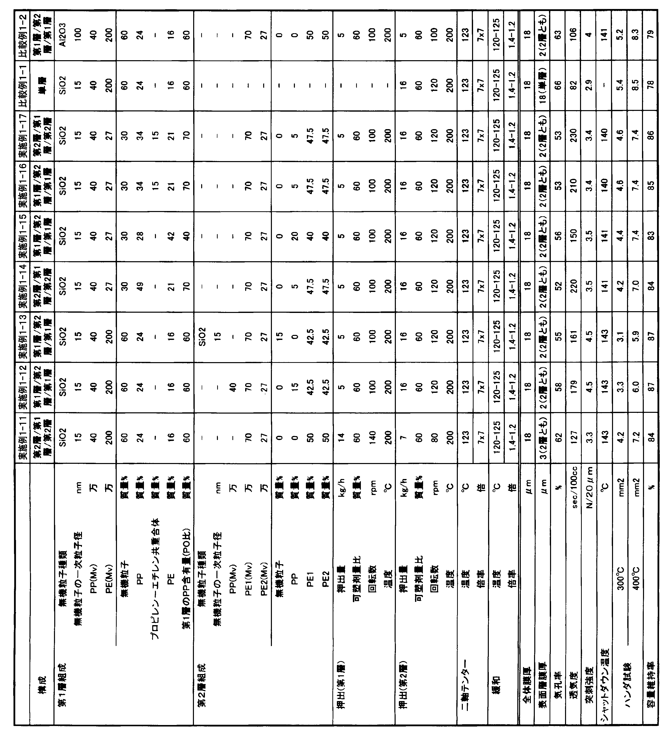
(1)実施例1-1~1-4と比較例1-1,1-2との対比から、一次粒子径が特定の範囲内である無機粒子を含有し、かつ積層構造を有する本実施形態1の積層セパレータは、一次粒子径が上記特定の範囲を逸脱する実施態様、又は積層構造を有しない実施態様に比し、耐熱性、サイクル特性、及びシャットダウン特性をバランス良く両立している。
(2)実施例1-1、及び実施例1-5~1-7の結果から、耐熱性、サイクル特性、及びシャットダウン特性を両立するという効果については、広範囲の無機粒子含有量において実現されている。
(3)実施例1-1、及び実施例1-8.1-9の結果から、耐熱性、サイクル特性、及びシャットダウン特性を両立するという効果については、広範囲のPP含有量において実現されている。
(4)実施例1-1、及び実施例1-10~1-13の結果から、耐熱性、サイクル特性、及びシャットダウン特性を両立するという効果については、種々の表層の厚さ、種々の層構成において実現されている。 The following contents can be read from the results of Tables 1 and 2 above.
(1) From the comparison between Examples 1-1 to 1-4 and Comparative Examples 1-1 and 1-2, this embodiment containing inorganic particles having a primary particle diameter within a specific range and having a laminated structure The laminated separator of
(2) From the results of Example 1-1 and Examples 1-5 to 1-7, the effect of achieving both heat resistance, cycle characteristics, and shutdown characteristics is realized in a wide range of inorganic particle contents. Yes.
(3) From the results of Example 1-1 and Example 1-8.1-9, the effect of achieving both heat resistance, cycle characteristics, and shutdown characteristics is realized in a wide range of PP contents. .
(4) From the results of Example 1-1 and Examples 1-10 to 1-13, regarding the effect of achieving both heat resistance, cycle characteristics, and shutdown characteristics, various surface layer thicknesses, various layers Realized in configuration.
次に、実施例及び比較例を挙げて本実施形態2をより具体的に説明するが、本実施形態2はその要旨を超えない限り、以下の実施例に限定されるものではない。なお、実施例中の物性は以下の方法により測定した。 [Embodiment 2]
Next, the second embodiment will be described more specifically with reference to examples and comparative examples. However, the second embodiment is not limited to the following examples as long as it does not exceed the gist thereof. In addition, the physical property in an Example was measured with the following method.
ASRM-D4020に基づき、デカリン溶剤における135℃での極限粘度[η]を求めた。
ポリエチレンのMvは次式により算出した。
[η]=0.00068×Mv0.67
ポリプロピレンのMvは次式より算出した。
[η]=1.10×Mv0.80
層のMvはポリエチレンの式を用いて算出した。 (1) Viscosity average molecular weight (Mv)
Based on ASRM-D4020, the intrinsic viscosity [η] at 135 ° C. in a decalin solvent was determined.
The Mv of polyethylene was calculated by the following formula.
[Η] = 0.00068 × Mv 0.67
Mv of polypropylene was calculated from the following formula.
[Η] = 1.10 × Mv 0.80
The Mv of the layer was calculated using the polyethylene equation.
微小測厚器(東洋精機製作所(株) タイプKBM)を用いて室温23±2℃で測定した。 (2) Film thickness (μm)
It measured at room temperature 23 +/- 2 degreeC using the micro thickness measuring device (Toyo Seiki Seisakusho Co., Ltd. type KBM).
10cm×10cm角の試料を微多孔膜から切り取り、その体積(cm3)と質量(g)を求め、それらと膜密度(g/cm3)より、次式を用いて計算した。
気孔率(%)=(体積-質量/混合組成物の密度)/体積×100
なお、混合組成物の密度は、用いたポリオレフィン樹脂と無機充填材の各々の密度と混合比より計算で求められる値を用いた。 (3) Porosity (%)
A sample of 10 cm × 10 cm square was cut out from the microporous membrane, its volume (cm 3 ) and mass (g) were determined, and calculated from these and the film density (g / cm 3 ) using the following formula.
Porosity (%) = (volume−mass / density of mixed composition) / volume × 100
In addition, the value calculated | required by calculation from the density and mixing ratio of each of the used polyolefin resin and an inorganic filler was used for the density of the mixed composition.
JIS P-8117準拠のガーレー式透気度計(東洋精機製)にて測定した。 (4) Air permeability (sec / 100cc)
It was measured with a Gurley type air permeability meter (manufactured by Toyo Seiki Co.) according to JIS P-8117.
カトーテック製、商標、KES-G5ハンディー圧縮試験器を用いて、針先端の曲率半径0.5mm、突刺速度2mm/secの条件で突刺試験を行い、最大突刺荷重を突刺強度(g)とした。 (5) Puncture strength (g)
A piercing test was conducted under the conditions of a radius of curvature of the needle tip of 0.5 mm and a piercing speed of 2 mm / sec using a trademark, KES-G5 handy compression tester manufactured by Kato Tech, and the maximum piercing load was defined as the piercing strength (g). .
電解液として、1mol/Lの六フッ化リン酸リチウム溶液(溶媒:プロピレンカーボネート)を使用し、グローブボックス内で該電解液を微多孔膜に滴下した。30秒後に電解液と液滴と微多孔膜が接している面の80%以上が透明であった場合を含浸性が良好(○)と判定し、80%未満であった場合を含浸性が十分ではない(×)と判定した。 (6) Electrolytic
エチレンカーボネート(EC):メチレンカーボネート(MEC)=1:2(重量比)からなる溶媒にLiPF61Mを添加した電解液を調製し、負極に炭素電極及び正極にLiCoO2を用い、セパレータとして測定試料の微多孔膜を用いたリチウムイオン電池を作製した。この電池を4.2Vに充電し、その後放電させる操作を25℃で100回繰り返すサイクル試験を行い、サイクル試験後の電池容量変化を調べた。 (7) Cycle characteristics (% / 100 times)
An electrolyte solution prepared by adding LiPF 6 1M to a solvent composed of ethylene carbonate (EC): methylene carbonate (MEC) = 1: 2 (weight ratio) was measured as a separator using a carbon electrode as a negative electrode and LiCoO 2 as a positive electrode. A lithium ion battery using a microporous membrane as a sample was produced. A cycle test in which this battery was charged to 4.2 V and then discharged was repeated 100 times at 25 ° C., and the change in battery capacity after the cycle test was examined.
図1(A)にシャットダウン温度の測定装置の概略図を示す。1は微多孔膜(測定対象としての積層セパレータ)であり、2A及び2Bは厚さ10μmのニッケル箔、3A及び3Bはガラス板である。4は電気抵抗測定装置(安藤電気製LCRメーター「AG-4311」(商標))でありニッケル箔2A、2Bと接続されている。5は熱電対であり温度計6と接続されている。7はデーターコレクターであり、電気抵抗装置4及び温度計6と接続されている。8はオーブンであり、微多孔膜を加熱する。
さらに詳細に説明すると、図1(B)に示すようにニッケル箔2A上に微多孔膜1を重ねて、縦方向に「テフロン(登録商標)」テープ(図の斜線部)でニッケル箔2Aに固定する。微多孔膜1には電解液として1mol/リットルのホウフッ化リチウム溶液(溶媒:プロピレンカーボネート/エチレンカーボネート/γ-ブチルラクトン=1/1/2)が含浸されている。ニッケル箔2B上には図1(C)に示すように「テフロン(登録商標)」テープ(図の斜線部)を貼り合わせ、箔2Bの中央部分に15mm×10mmの窓の部分を残してマスキングした。
ニッケル箔2Aとニッケル箔2Bを微多孔膜1をはさむような形で重ね合わせ、さらにその両側からガラス板3A、3Bによって2枚のニッケル箔をはさみこんだ。このとき、箔2Bの窓の部分と、微多孔膜1が相対する位置に来るようにした。
2枚のガラス板は市販のダブルクリップではさむことにより固定した。熱電対5は「テフロン(登録商標)」テープでガラス板に固定した。
このような装置で連続的に温度と電気抵抗を測定した。なお、温度は25℃から200℃まで2℃/minの速度にて昇温させ、電気抵抗値は1V、1kHzの交流にて測定した。シャットダウン温度とは微多孔膜の電気抵抗値が103Ωに達するときの温度、膜がシャットダウンし、孔が閉塞状態に達した後、再びインピーダンスが103Ωを下回った時点の温度をショート温度とした。 (8) Shutdown temperature (° C), short-circuit temperature (° C)
FIG. 1A shows a schematic diagram of a shutdown temperature measuring device. 1 is a microporous film (laminated separator as a measurement object), 2A and 2B are nickel foils having a thickness of 10 μm, and 3A and 3B are glass plates. 4 is an electrical resistance measuring device (LCR meter “AG-4411” (trademark) manufactured by Ando Electric Co., Ltd.), which is connected to the nickel foils 2A and 2B. A
More specifically, as shown in FIG. 1 (B), the
The
Two glass plates were fixed by pinching with a commercially available double clip. The
Temperature and electric resistance were continuously measured with such an apparatus. The temperature was raised from 25 ° C. to 200 ° C. at a rate of 2 ° C./min, and the electrical resistance value was measured at 1 V and 1 kHz alternating current. The shutdown temperature is the temperature at which the electrical resistance value of the microporous membrane reaches 10 3 Ω, and the temperature at which the impedance again falls below 10 3 Ω after the membrane shuts down and the pores are closed, is the short temperature. It was.
下記の条件で測定する13C-NMRスペクトルから、Kakugoらの報告(Macromolecules 1982,15,1150-1152)に基づいて求めた。10mmΦの試験管中で約200mgのプロピレン-エチレンブロック共重合体を3mlのオルソジクロロベンゼンに均一に溶解させて試料を調製し、以下の条件にて測定を行った。
測定温度:135℃
パルス繰り返し時間:10秒
パルス幅:45°
積算回数:2500回 (9) Ethylene content in polypropylene-ethylene copolymer The ethylene content was determined from a 13C-NMR spectrum measured under the following conditions based on a report by Kakugo et al. (Macromolecules 1982, 15, 1150-1152). A sample was prepared by uniformly dissolving about 200 mg of propylene-ethylene block copolymer in 3 ml of orthodichlorobenzene in a 10 mmφ test tube, and the measurement was performed under the following conditions.
Measurement temperature: 135 ° C
Pulse repetition time: 10 seconds Pulse width: 45 °
Integration count: 2500 times
FRONTEX S410可塑剤吸油量測定器を用いて次のように測定した。無機充填材5gを投入し、混練しながら可塑剤(パラフィン油)を滴下した。混練時のトルクが上昇し、最大トルクの70%に減少するときの可塑剤添加量(ml)を求め、それと無機充填材重量(g)より、次式を用いて計算した。
可塑剤吸油量(ml/100g)=可塑剤添加量/無機充填材重量×100 (10) Plasticizer oil absorption amount of inorganic filler The FRONTEX S410 plasticizer oil absorption amount measuring device was measured as follows. 5 g of inorganic filler was added, and a plasticizer (paraffin oil) was added dropwise while kneading. The amount of plasticizer added (ml) when the torque at the time of kneading increased and decreased to 70% of the maximum torque was determined, and was calculated from this and the weight (g) of the inorganic filler using the following formula.
Plasticizer oil absorption (ml / 100 g) = Plasticizer addition / Inorganic filler weight × 100
粘度平均分子量40万のポリプロピレン(融点163℃)21.2質量部(78質量%)、粘度平均分子量25万、エチレン含有量3質量%のプロピレン-エチレン共重合体(融点160℃)0.4質量部(2質量%)、粘度平均分子量25万の高密度ポリエチレン(融点137℃)5.4質量部(20質量%)、核剤としてビス(p-エチルベンジリデン)ソルビトールを0.3質量部、酸化防止剤としてテトラキス-[メチレン-(3’,5’-ジ-t-ブチル-4’-ヒドロキシフェニル)プロピオネート]メタンを0.2質量部、パラフィン油(松村石油研究所製:P350P)63質量部(70質量%)を配合し原料を調製した。配合物をバッチ式溶融混練機(東洋精機社製:ラボプラストミル)を用いて200℃・50rpmで10分間混練した。得られた混練物を200℃の加熱プレスで5MPaにて成形し3分間そのまま熱処理をした後、25℃に制御された水冷プレスで5MPaにて冷却し、厚さ500μmのシートとした。これを同時2軸延伸機(東洋精機社製)を用いて4×4倍に120℃で延伸し、その後塩化メチレンでパラフィン油を抽出除去し、乾燥させた。得られたポリエチレン微多孔膜の物性を表3に示す。 [Example 2-1]
21.2 parts by mass (78% by mass) of polypropylene having a viscosity average molecular weight of 400,000 (melting point 163 ° C.), propylene-ethylene copolymer having a viscosity average molecular weight of 250,000 and 3% by mass of ethylene (melting point 160 ° C.) 0.4 5.4 parts by mass (2% by mass), high-density polyethylene having a viscosity average molecular weight of 250,000 (melting point: 137 ° C.), 5.4 parts by mass (20% by mass), and 0.3 parts by mass of bis (p-ethylbenzylidene) sorbitol as a nucleating agent 0.2 parts by mass of tetrakis- [methylene- (3 ′, 5′-di-t-butyl-4′-hydroxyphenyl) propionate] methane as an antioxidant, paraffin oil (manufactured by Matsumura Oil Research Institute: P350P) A raw material was prepared by blending 63 parts by mass (70% by mass). The blend was kneaded for 10 minutes at 200 ° C. and 50 rpm using a batch melt kneader (Toyo Seiki Co., Ltd .: Labo Plast Mill). The obtained kneaded material was molded at 5 MPa with a 200 ° C. hot press and heat treated for 3 minutes as it was, and then cooled at 5 MPa with a water-cooled press controlled at 25 ° C. to obtain a sheet having a thickness of 500 μm. This was stretched 4 × 4 times at 120 ° C. using a simultaneous biaxial stretching machine (manufactured by Toyo Seiki Co., Ltd.), and then the paraffin oil was extracted and removed with methylene chloride and dried. Table 3 shows the physical properties of the obtained polyethylene microporous membrane.
表3に示す条件以外は実施例2-1と同様にしてポリエチレン微多孔膜を得た。得られたポリエチレン微多孔膜の物性を表3に示す。
なお、無機充填材として使用されるシリカの吸油量は200mL/100gであった。 [Examples 2-2 to 2-5, Comparative Examples 2-1 to 2-3]
A polyethylene microporous membrane was obtained in the same manner as in Example 2-1, except for the conditions shown in Table 3. Table 3 shows the physical properties of the obtained polyethylene microporous membrane.
In addition, the oil absorption amount of the silica used as an inorganic filler was 200 mL / 100g.
粘度平均分子量40万のポリプロピレン(融点163℃)31.4質量部、粘度平均分子量25万、エチレン含有量3質量%のプロピレン-エチレン共重合体(融点160℃)0.6質量部、粘度平均分子量25万の高密度ポリエチレン(融点137℃)8.0質量部、核剤としてビス(p-エチルベンジリデン)ソルビトールを0.3質量部、酸化防止剤としてテトラキス-[メチレン-(3’、5’-ジ-t-ブチル-4’-ヒドロキシフェニル)プロピオネート]メタンを0.2質量部、可塑剤として流動パラフィン(松村石油研究所製:P350P)9.6質量部をミキサーで攪拌し、表面層の原料を調製した。
粘度平均分子量25万の高密度ポリエチレン14.25質量部、粘度平均分子量70万の高密度ポリエチレン14.25質量部、粘度平均分子量40万のポリプロピレン1.5質量部、酸化防止剤としてテトラキス-[メチレン-(3’、5’-ジ-t-ブチル-4’-ヒドロキシフェニル)プロピオネート]メタンを0.2質量部配合し、中間層の原料を調製した。
各配合物は2台の口径25mm、L/D=48の二軸押出機フィーダーを介して投入した。さらに、表面層の原料には流動パラフィン65質量部、中間層の原料には流動パラフィン70質量部をサイドフィードでそれぞれの押出機に注入し、両表面層、中間層の押出量がそれぞれ、1時間当たり4kg、16kgとなるように調整し、200℃、200rpmの条件で混練した後、押出機先端に取り付けた共押出(二種三層)が可能なTダイから220℃の条件で押出した。ただちに、表面温度70℃に制御されたロールに押出し、さらに表面温度25℃に制御されたロールにて冷却させ、厚さ1.4mmのシートを成形した。このシートを同時二軸延伸機で123℃の条件で7×7倍に延伸した後、塩化メチレンに浸漬して、流動パラフィンを抽出除去後乾燥し、テンター延伸機により119℃の条件で横方向に1.4倍延伸した。その後、この延伸シートを124℃で21%幅方向に緩和して熱処理を行い、表面層の二層が同一の組成で、中間層が異なる組成の二種三層構造を有する微多孔膜を得た。得られた微多孔膜の物性を表4に示す。 [Example 2-6]
31.4 parts by weight of a polypropylene having a viscosity average molecular weight of 400,000 (melting point: 163 ° C.), 0.6 part by weight of a propylene-ethylene copolymer having a viscosity average molecular weight of 250,000 and an ethylene content of 3% by weight (melting point: 160 ° C.), a viscosity average 8.0 parts by mass of a high-density polyethylene having a molecular weight of 250,000 (melting point 137 ° C.), 0.3 parts by mass of bis (p-ethylbenzylidene) sorbitol as a nucleating agent, and tetrakis- [methylene- (3 ′, 5 '-Di-t-butyl-4'-hydroxyphenyl) propionate] 0.2 parts by mass of methane and 9.6 parts by mass of liquid paraffin (manufactured by Matsumura Oil Research Institute: P350P) as a plasticizer were stirred with a mixer, and the surface Layer raw materials were prepared.
14.25 parts by mass of high density polyethylene having a viscosity average molecular weight of 250,000, 14.25 parts by mass of high density polyethylene having a viscosity average molecular weight of 700,000, 1.5 parts by mass of polypropylene having a viscosity average molecular weight of 400,000, tetrakis- [ Methylene- (3 ′, 5′-di-t-butyl-4′-hydroxyphenyl) propionate] methane was blended in an amount of 0.2 part by mass to prepare a raw material for the intermediate layer.
Each compound was charged through two twin screw extruder feeders having a diameter of 25 mm and L / D = 48. Further, 65 parts by mass of liquid paraffin as the raw material for the surface layer and 70 parts by mass of liquid paraffin as the raw material for the intermediate layer are injected into each extruder by side feed, and the extrusion amounts of both the surface layer and the intermediate layer are 1 respectively. After adjusting to 4 kg and 16 kg per hour, kneading under conditions of 200 ° C. and 200 rpm, extrusion was performed at 220 ° C. from a T-die capable of coextrusion (two types and three layers) attached to the tip of the extruder. . Immediately, the sheet was extruded into a roll controlled at a surface temperature of 70 ° C., and further cooled by a roll controlled at a surface temperature of 25 ° C. to form a sheet having a thickness of 1.4 mm. This sheet was stretched 7 × 7 times at 123 ° C. with a simultaneous biaxial stretching machine, then dipped in methylene chloride, extracted by removing liquid paraffin, dried, and transversely at 119 ° C. with a tenter stretching machine. The film was stretched 1.4 times. Thereafter, this stretched sheet is heat-treated at 124 ° C. in a 21% width direction to obtain a microporous membrane having a two-layer / three-layer structure in which the two layers of the surface layer have the same composition and the intermediate layer has a different composition. It was. Table 4 shows the physical properties of the obtained microporous membrane.
表4に示す条件以外は実施例2-6と同様にしてポリエチレン微多孔膜を得た。得られたポリエチレン微多孔膜の物性を表4に示す。
[実施例2-16]
ポリオレフィン第1微多孔層の原料を粘度平均分子量40万のポリプロピレン(融点163℃)を24.4質量部、粘度平均分子量25万、エチレン含有量3質量%のプロピレン-エチレン共重合体(融点160℃)を1.2質量部、粘度平均分子量25万の高密度ポリエチレン(融点137℃)を5.9質量部、粘度平均分子量1000のポリエチレン(融点120℃)を0.5質量部、平均一次粒径が15nmであるシリカを8質量部とした以外は実施例2-6と同様にして二種三層構造を有する微多孔膜を得た。
得られた積層セパレータはシャットダウン特性に優れていた。
なお、無機充填材として使用されるシリカの吸油量は200mL/100gであった。 [Examples 2-7 to 2-15, Comparative Examples 2-4 to 2-5]
Except for the conditions shown in Table 4, a polyethylene microporous membrane was obtained in the same manner as in Example 2-6. Table 4 shows the physical properties of the obtained polyethylene microporous membrane.
[Example 2-16]
The raw material of the first polyolefin microporous layer is a polypropylene (melting point 163 ° C.) having a viscosity average molecular weight of 24.4 parts by mass, a propylene-ethylene copolymer having a viscosity average molecular weight of 250,000 and an ethylene content of 3% by mass (melting point 160). ° C) 1.2 parts by mass, 5.9 parts by mass of high density polyethylene (melting point 137 ° C) with a viscosity average molecular weight of 250,000, 0.5 parts by mass of polyethylene with a viscosity average molecular weight 1000 (melting point 120 ° C), average primary A microporous membrane having a two-kind-three-layer structure was obtained in the same manner as in Example 2-6, except that 8 parts by mass of silica having a particle size of 15 nm was used.
The obtained laminated separator was excellent in shutdown characteristics.
In addition, the oil absorption amount of the silica used as an inorganic filler was 200 mL / 100g.
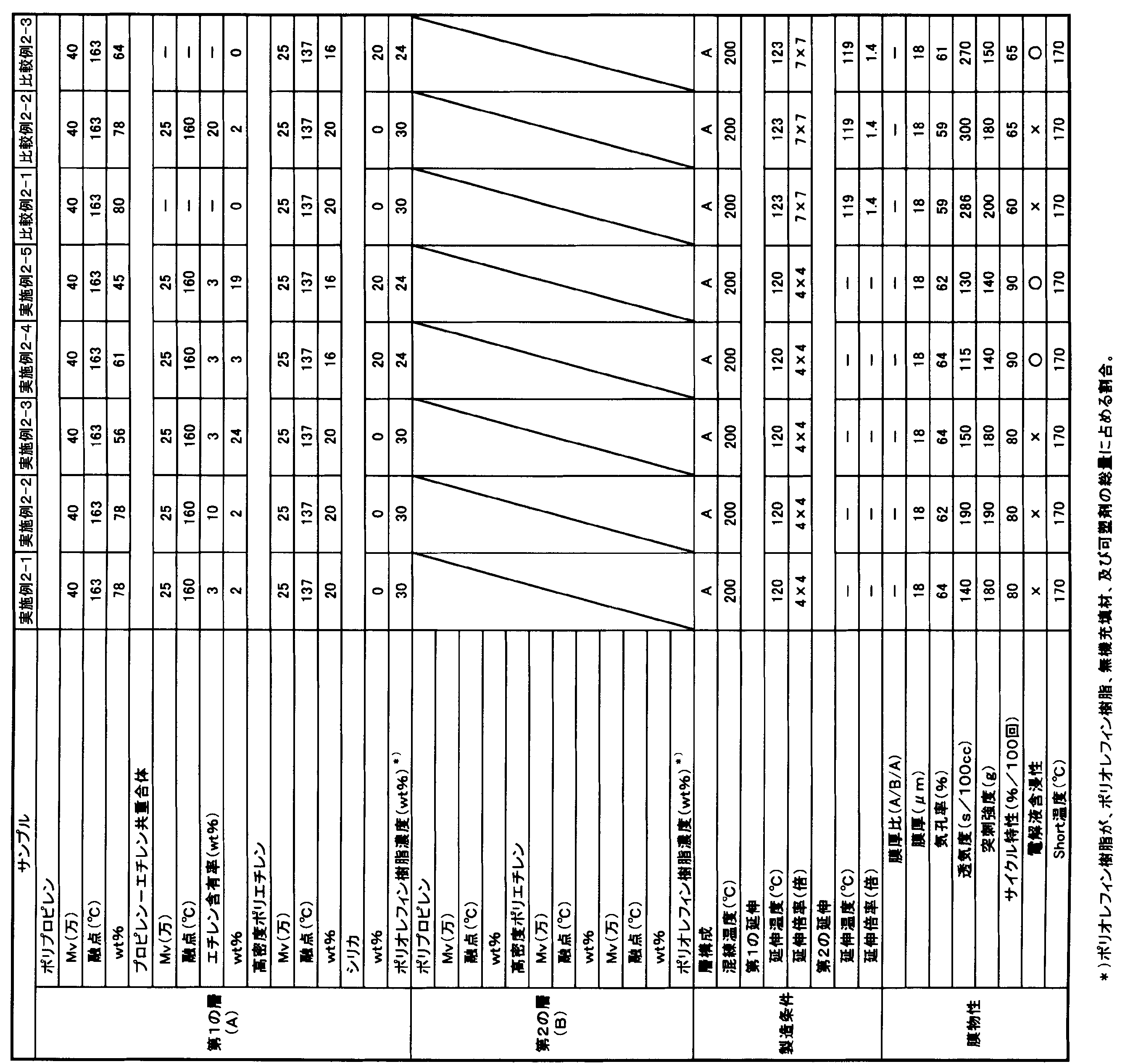
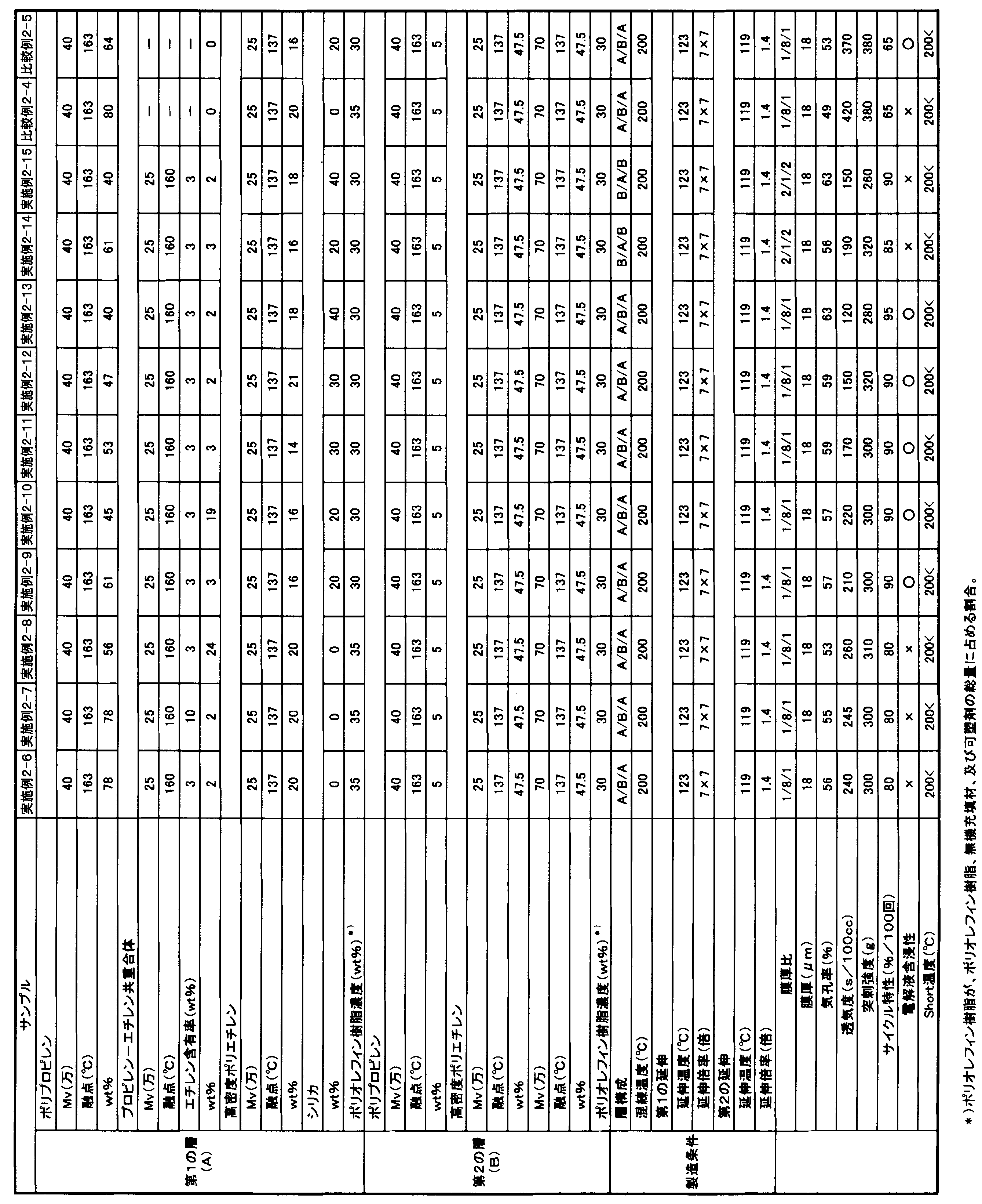
[本実施形態3]
次に、実施例及び比較例を挙げて本実施形態3をより具体的に説明するが、本実施形態3はその要旨を超えない限り、以下の実施例に限定されるものではない。なお、実施例中の物性は以下の方法により測定した。 As is clear from the results of Tables 3 and 4, the microporous membrane of the second embodiment is suitable as a separator that can improve the cycle characteristics of the electricity storage device.
[Third Embodiment]
Next, the third embodiment will be described more specifically with reference to examples and comparative examples. However, the third embodiment is not limited to the following examples as long as it does not exceed the gist thereof. In addition, the physical property in an Example was measured with the following method.
島津製作所社製DSC60を使用し測定した。試料を3mg採取し測定サンプルとして用いた。これを直径5mmのアルミ製オープンサンプルパンに敷き詰め、クランピングカバーを乗せサンプルシーラーでアルミパン内に固定した。窒素雰囲気下、昇温速度10℃/minで30℃から200℃までを測定し、融解吸熱曲線を得た。得られた融解吸熱曲線について、85℃~175℃の範囲に直線ベースラインを設定し、係る直線ベースラインと吸熱融解曲線とで囲まれる部分の面積から熱量を算出し、これを試料質量当たりに換算して、融解熱を算出した。また、同様にして融解熱ΔHと吸熱融解曲線における極小値の温度を融点として測定した。 (1) Melting point (° C)
It measured using DSC60 by Shimadzu Corporation. 3 mg of a sample was collected and used as a measurement sample. This was spread on an aluminum open sample pan having a diameter of 5 mm, and a clamping cover was placed thereon and fixed in the aluminum pan with a sample sealer. Under a nitrogen atmosphere, the temperature was increased from 30 ° C. to 200 ° C. at a rate of temperature increase of 10 ° C./min to obtain a melting endothermic curve. About the obtained melting endothermic curve, a linear baseline is set in the range of 85 ° C. to 175 ° C., and the amount of heat is calculated from the area surrounded by the linear baseline and the endothermic melting curve. In conversion, the heat of fusion was calculated. Similarly, the temperature of the minimum value in the heat of fusion ΔH and the endothermic melting curve was measured as the melting point.
積層セパレータから測定対象を採取し、走査型電子顕微鏡を用いて30000倍で観察し、縦3.0μm、横3.0μmの視野像の中で無機粒子径を確認した。なお、「一次粒子径」とは個々の粒子が単独でマトリックス中に分散している状態での粒子径、または凝集していても、その中で構成されている最小の粒子径を意味する。また、測定値は、10点の観察値の平均値とした。 (2) Primary particle diameter of inorganic particles (nm)
An object to be measured was collected from the laminated separator and observed at a magnification of 30000 using a scanning electron microscope, and the inorganic particle diameter was confirmed in a field image of 3.0 μm in length and 3.0 μm in width. The “primary particle diameter” means a particle diameter in a state where individual particles are dispersed in a matrix alone, or a minimum particle diameter formed in the aggregate even if they are aggregated. Moreover, the measured value was made into the average value of 10 observation values.
a.正極の作成
正極活物質としてリチウムコバルト複合酸化物(LiCoO2)を92.2質量%、導電材としてリン片状グラファイトとアセチレンブラックをそれぞれ2.3質量%、バインダーとしてポリフッ化ビニリデン(PVDF)3.2質量%をN-メチルピロリドン(NMP)中に分散させてスラリーを調製した。このスラリーを正極集電体となる厚さ20μmのアルミニウム箔の片面にダイコーターで塗布し、130℃で3分間乾燥後、ロールプレス機で圧縮成形した。この時、正極の活物質塗布量は250g/m2、活物質嵩密度は3.00g/cm3になるようにした。
b.負極の作成
負極活物質として人造グラファイト96.9質量%、バインダーとしてカルボキシメチルセルロースのアンモニウム塩1.4質量%とスチレン-ブタジエン共重合体ラテックス1.7質量%を精製水中に分散させてスラリーを調製した。このスラリーを負極集電体となる厚さ12μmの銅箔の片面にダイコーターで塗布し、120℃で3分間乾燥後、ロールプレス機で圧縮成形した。この時、負極の活物質塗布量は106g/m2、活物質嵩密度は1.35g/cm3になるようにした。
c.非水電解液の調製
エチレンカーボネート:エチルメチルカーボネート=1:2(体積比)の混合溶媒に、溶質としてLiPF6を濃度1.0mol/Lとなるように溶解させて調製した。
d.電池組立
セパレータを30mmφ、正極及び負極を16mmφの円形に切り出し、正極と負極の活物質面が対向するよう、負極、セパレータ、正極の順に重ね、蓋付きステンレス金属製容器に収納した。容器と蓋は絶縁されており、容器は負極の銅箔と、蓋は正極のアルミニウム箔と接していた。この容器内に前記した非水電解液を注入して密閉した。室温にて一日放置した後、25℃雰囲気下、2.0mA(0.33C)の電流値で電池電圧4.2Vまで充電し、到達後4.2Vを保持するようにして電流地を2.0mAから絞り始めるという方法で、合計8時間電池作成後の最初の充電を行った。続いて2.0mA(0.33C)の電流値で電池電圧3.0Vまで放電した。
e.容量維持率(%)
充放電は60℃雰囲気下で100サイクル実施した。充電は6.0mA(1.0C)の電流値で電池電圧4.2Vまで充電し、到達後4.2Vを保持するようにして電流値を6.0mAから絞り始めるという方法で、合計3時間充電した。放電は6.0mA(1.0C)の電流値で電池電圧3.0Vまで放電した。100サイクル目の放電容量と1サイクル目の放電容量から、容量維持率を算出した。容量維持率が高い場合、良好なサイクル特性を有するものと評価した。 (3) Cycle characteristics (% / 100 times)
a. Preparation of positive electrode 92.2% by mass of lithium cobalt composite oxide (LiCoO 2 ) as a positive electrode active material, 2.3% by mass of flake graphite and acetylene black as a conductive material, and polyvinylidene fluoride (PVDF) 3 as a binder A slurry was prepared by dispersing 2% by mass in N-methylpyrrolidone (NMP). This slurry was applied to one side of a 20 μm thick aluminum foil serving as a positive electrode current collector with a die coater, dried at 130 ° C. for 3 minutes, and then compression molded with a roll press. At this time, the active material coating amount of the positive electrode was 250 g / m 2 and the active material bulk density was 3.00 g / cm 3 .
b. Preparation of negative electrode 96.9% by mass of artificial graphite as negative electrode active material, 1.4% by mass of ammonium salt of carboxymethyl cellulose and 1.7% by mass of styrene-butadiene copolymer latex as a binder were dispersed in purified water to prepare a slurry. did. This slurry was applied to one side of a 12 μm thick copper foil serving as a negative electrode current collector with a die coater, dried at 120 ° C. for 3 minutes, and then compression molded with a roll press. At this time, the active material application amount of the negative electrode was set to 106 g / m 2 , and the active material bulk density was set to 1.35 g / cm 3 .
c. Preparation of Nonaqueous Electrolytic Solution Prepared by dissolving LiPF 6 as a solute in a mixed solvent of ethylene carbonate: ethyl methyl carbonate = 1: 2 (volume ratio) to a concentration of 1.0 mol / L.
d. Battery assembly A separator was cut into a circle of 30 mmφ and a positive electrode and a negative electrode were cut into a circle of 16 mmφ, and the negative electrode, the separator, and the positive electrode were stacked in this order so that the active material surfaces of the positive electrode and the negative electrode faced each other. The container and the lid were insulated, and the container was in contact with the negative electrode copper foil and the lid was in contact with the positive electrode aluminum foil. The above-mentioned non-aqueous electrolyte was poured into this container and sealed. After standing at room temperature for a day, the battery is charged to a battery voltage of 4.2 V at a current value of 2.0 mA (0.33 C) in an atmosphere of 25 ° C. The battery was first charged after making the battery for a total of 8 hours by starting from 0.0 mA. Subsequently, the battery was discharged to a battery voltage of 3.0 V at a current value of 2.0 mA (0.33 C).
e. Capacity maintenance rate (%)
Charging / discharging was performed 100 cycles in a 60 ° C. atmosphere. Charging is performed at a current value of 6.0 mA (1.0 C) up to a battery voltage of 4.2 V, and after reaching the voltage, the current value starts to be reduced from 6.0 mA so as to hold 4.2 V, for a total of 3 hours. Charged. The battery was discharged at a current value of 6.0 mA (1.0 C) to a battery voltage of 3.0 V. The capacity retention rate was calculated from the discharge capacity at the 100th cycle and the discharge capacity at the first cycle. When the capacity retention rate was high, it was evaluated as having good cycle characteristics.
上記a~dのように組み立てた簡易電池を25℃雰囲気下、3mA(約0.5C)の電流値で電池電圧4.2Vまで充電し、到達後4.2Vを保持するようにして電流値を3mAから絞り始めるという方法で、合計6時間の充電を行った。そして3mAの電流値で電池電圧3.0Vまで放電した。
次に25℃雰囲気下、6mA(約1.0C)の電流値で電池電圧4.2Vまで充電し、到達後4.2Vを保持するようにして電流値を6mAから絞り始めるという方法で、合計3時間充電を行った。そして6mAの電流値で電池電圧3.0Vまで放電する。このときの放電容量をA(mAh)とした。
次に25℃雰囲気下、6mA(約1.0C)の電流値で電池電圧4.2Vまで充電し、到達後4.2Vを保持するようにして電流値を6mAから絞り始めるという方法で、合計3時間充電を行った。充電状態に保持したセルを60℃雰囲気下で7日間保持した。その後セルを取り出し25℃雰囲気下、6mAの電流値で電池電圧3.0Vまで放電した。次に25℃雰囲気下、6mA(約1.0C)の電流値で電池電圧4.2Vまで充電し、到達後4.2Vを保持するようにして電流値を6mAから絞り始めるという方法で、合計3時間充電を行った。そして6mAの電流値で電池電圧3.0Vまで放電した。このときの放電容量をB(mAh)とした。BのAに対する比率から、容量維持率を高温保存特性として算出した。 (4) High temperature storage characteristics evaluation (%)
A simple battery assembled as described above a to d is charged to a battery voltage of 4.2 V at a current value of 3 mA (about 0.5 C) in an atmosphere of 25 ° C., and the current value is maintained to 4.2 V after reaching the battery voltage. The battery was charged for a total of 6 hours by starting to squeeze from 3 mA. And it discharged to the battery voltage 3.0V with the electric current value of 3 mA.
Next, in a 25 ° C. atmosphere, the battery voltage is charged to 4.2 V at a current value of 6 mA (about 1.0 C), and after reaching the voltage value, the current value starts to be reduced from 6 mA so as to maintain 4.2 V. The battery was charged for 3 hours. And it discharges to battery voltage 3.0V with the electric current value of 6 mA. The discharge capacity at this time was A (mAh).
Next, in a 25 ° C. atmosphere, the battery voltage is charged to 4.2 V at a current value of 6 mA (about 1.0 C), and after reaching the voltage value, the current value starts to be reduced from 6 mA so as to maintain 4.2 V. The battery was charged for 3 hours. The cell held in a charged state was held in a 60 ° C. atmosphere for 7 days. Thereafter, the cell was taken out and discharged in a 25 ° C. atmosphere to a battery voltage of 3.0 V at a current value of 6 mA. Next, in a 25 ° C. atmosphere, the battery voltage is charged to 4.2 V at a current value of 6 mA (about 1.0 C), and after reaching the voltage value, the current value starts to be reduced from 6 mA so as to maintain 4.2 V. The battery was charged for 3 hours. And it discharged to battery voltage 3.0V with the electric current value of 6 mA. The discharge capacity at this time was B (mAh). From the ratio of B to A, the capacity retention rate was calculated as a high temperature storage characteristic.
図1(A)にシャットダウン温度の測定装置の概略図を示す。1は微多孔膜(測定対象としての積層セパレータ)であり、2A及び2Bは厚さ10μmのニッケル箔、3A及び3Bはガラス板である。4は電気抵抗測定装置(安藤電気製LCRメーター「AG-4311」(商標))でありニッケル箔2A、2Bと接続されている。5は熱電対であり温度計6と接続されている。7はデーターコレクターであり、電気抵抗装置4及び温度計6と接続されている。8はオーブンであり、微多孔膜を加熱する。
さらに詳細に説明すると、図1(B)に示すようにニッケル箔2A上に微多孔膜1を重ねて、縦方向に「テフロン(登録商標)」テープ(図の斜線部)でニッケル箔2Aに固定する。微多孔膜1には電解液として1mol/リットルのホウフッ化リチウム溶液(溶媒:プロピレンカーボネート/エチレンカーボネート/γ-ブチルラクトン=1/1/2)が含浸されている。ニッケル箔2B上には図1(C)に示すように「テフロン(登録商標)」テープ(図の斜線部)を貼り合わせ、箔2Bの中央部分に15mm×10mmの窓の部分を残してマスキングした。
ニッケル箔2Aとニッケル箔2Bを微多孔膜1をはさむような形で重ね合わせ、さらにその両側からガラス板3A、3Bによって2枚のニッケル箔をはさみこんだ。このとき、箔2Bの窓の部分と、微多孔膜1が相対する位置に来るようにした。
2枚のガラス板は市販のダブルクリップではさむことにより固定した。熱電対5は「テフロン(登録商標)」テープでガラス板に固定した。
このような装置で連続的に温度と電気抵抗を測定した。なお、温度は25℃から200℃まで2℃/minの速度にて昇温させ、電気抵抗値は1V、1kHzの交流にて測定した。シャットダウン温度とは微多孔膜の電気抵抗値が103Ωに達するときの温度、膜がシャットダウンし、孔が閉塞状態に達した後、再びインピーダンスが103Ωを下回った時点の温度をショート温度とした。 (5) Shutdown temperature (° C), short-circuit temperature (° C)
FIG. 1A shows a schematic diagram of a shutdown temperature measuring device. 1 is a microporous film (laminated separator as a measurement object), 2A and 2B are nickel foils having a thickness of 10 μm, and 3A and 3B are glass plates. 4 is an electrical resistance measuring device (LCR meter “AG-4411” (trademark) manufactured by Ando Electric Co., Ltd.), which is connected to the nickel foils 2A and 2B. A
More specifically, as shown in FIG. 1 (B), the
The
Two glass plates were fixed by pinching with a commercially available double clip. The
Temperature and electric resistance were continuously measured with such an apparatus. The temperature was raised from 25 ° C. to 200 ° C. at a rate of 2 ° C./min, and the electrical resistance value was measured at 1 V and 1 kHz alternating current. The shutdown temperature is the temperature at which the electrical resistance value of the microporous membrane reaches 10 3 Ω, and the temperature at which the impedance again falls below 10 3 Ω after the membrane shuts down and the pores are closed, is the short temperature. It was.
プロピレン共重合体中のコモノマー(エチレン及びα-オレフィン)の同定、及びその含有率の測定はC.J.Carmanらによって報告されている13C-NMR法による方法(Macromolecules,10,537(1977)をもとに行った。 (6) Content of copolymerized monomer The identification of comonomer (ethylene and α-olefin) in propylene copolymer and measurement of the content thereof were carried out by the 13C-NMR method reported by CJ Carman et al. , 10,537 (1977).
キャピラリー内部の流体は、流体の平均自由工程がキャピラリーの孔径より小さいときはポアズイユの流れ、大きいときはクヌーセンの流れに従うことが知られている。ここで、透気度測定における空気の流れがクヌーセンの流れ、常温での透水度測定における水の流れがポアズイユの流れに従うと仮定すると、平均孔径d(m)及び孔屈曲率τ(無次元)は、空気の透過速度定数Rgas,水の透過速度定数Rliq,水の粘度η(Pa・sec),標準圧力Ps(101325Pa),気孔率ε(無次元),膜厚L(m),気体の分子速度ν(m/sec)から、次式を用いて求めることができる;
d=2ν(Rliq/Rgas)(16η/3)(1/Ps)
ここで、Rgas は透気度(sec)から次式を用いて求められる;
Rgas(m3/(m2・sec・Pa))=0.0001/透気度/0.0006424/(0.01276×101325)
また、Rliq は透水度(cm3/(cm2・sec・Pa))から次式を用いて求められる
Rliq(m3/m2・sec・Pa)=透水度/1000000/0.0001
上記式中の透水度は以下のようにして測定する;
直径42mmのステンレス製の透液セルに、あらかじめエタノールに浸しておいた微多孔膜をセットし、該膜のエタノールを水で洗浄した後、約50000Paの差圧で水を透過させ、120秒間経過した際の透水量(cm3)から、単位時間,単位圧力,単位面積当たりの透水量を計算し、これを透水度(cm3/(cm2・sec・Pa))とする。
さらに、νは気体定数R(8.314J/mol・K),絶対温度T(K),円周率π,気体の平均分子量M(=2.896×10-2)(kg/mol)から次式を用いて求められる;
ν2=8RT/πM (7) Mean pore diameter It is known that the fluid inside the capillary follows the flow of Poiseuille when the mean free path of the fluid is smaller than the pore diameter of the capillary and the flow of Knudsen when it is larger. Here, assuming that the air flow in the air permeability measurement follows the Knudsen flow, and the water flow in the water temperature measurement at room temperature follows the Poiseuille flow, the average pore diameter d (m) and the hole bending rate τ (dimensionless) Is the air permeation rate constant Rgas, the water permeation rate constant Rliq, the water viscosity η (Pa · sec), the standard pressure Ps (101325 Pa), the porosity ε (dimensionless), the film thickness L (m), From the molecular velocity ν (m / sec), it can be determined using the following formula:
d = 2ν (Rliq / Rgas) (16η / 3) (1 / Ps)
Where Rgas is determined from the air permeability (sec) using the following equation:
Rgas (m 3 / (m 2 · sec · Pa)) = 0.0001 / air permeability / 0.0006424 / (0.01276 × 101325)
Rliq is determined from the water permeability (cm 3 / (cm 2 · sec · Pa)) using the following formula: Rliq (m 3 / m 2 · sec · Pa) = water permeability / 1000000 / 0.0001
The water permeability in the above formula is measured as follows:
A microporous membrane previously immersed in ethanol was set in a stainless steel liquid-permeable cell having a diameter of 42 mm, and after the ethanol in the membrane was washed with water, water was permeated at a differential pressure of about 50000 Pa, and 120 seconds passed. The amount of water per unit time, unit pressure, and unit area is calculated from the amount of water permeated (cm 3 ), and this is defined as the water permeability (cm 3 / (cm 2 · sec · Pa)).
Furthermore, ν is obtained from the gas constant R (8.314 J / mol · K), the absolute temperature T (K), the circumference π, and the average molecular weight M (= 2.896 × 10 −2 ) (kg / mol) of the gas. Obtained using the following formula:
ν2 = 8RT / πM
粘度平均分子量40万のポリプロピレン(融点163℃)50.4質量部、粘度平均分子量25万、エチレン含有量5質量%、融解熱70J/gのプロピレン-エチレンランダム共重合体(融点140℃)12.6質量部、核剤としてビス(p-エチルベンジリデン)ソルビトールを0.3質量部、酸化防止剤としてテトラキス-[メチレン-(3’,5’-ジ-t-ブチル-4’-ヒドロキシフェニル)プロピオネート]メタンを0.2質量部、パラフィン油(松村石油研究所製:P350P、可塑剤密度0.868g/cm3)63質量部を配合し原料を調製した。配合物をバッチ式溶融混練機(東洋精機社製:ラボプラストミル)を用いて200℃・50rpmで10分間混練した。得られた混練物を200℃の加熱プレスで5MPaにて成形し3分間そのまま熱処理をした後、25℃に制御された水冷プレスで5MPaにて冷却し、厚さ500μmのシートとした。これを同時2軸延伸機(東洋精機社製)を用いて5×5倍に125℃で延伸し、その後塩化メチレンでパラフィン油を抽出除去し、乾燥させた。得られたポリエチレン微多孔膜の物性を表5に示す。 [Example 3-1]
Propylene-ethylene random copolymer (melting point: 140 ° C.) having a viscosity average molecular weight of 400,000 (melting point: 163 ° C.) 50.4 parts by mass, a viscosity average molecular weight of 250,000, an ethylene content of 5% by mass, and a heat of fusion of 70 J / g. .6 parts by mass, 0.3 parts by mass of bis (p-ethylbenzylidene) sorbitol as a nucleating agent, and tetrakis- [methylene- (3 ′, 5′-di-t-butyl-4′-hydroxyphenyl) as an antioxidant ) Propionate] 0.2 parts by mass of methane and 63 parts by mass of paraffin oil (manufactured by Matsumura Oil Research Institute: P350P, plasticizer density 0.868 g / cm 3 ) were blended to prepare a raw material. The blend was kneaded for 10 minutes at 200 ° C. and 50 rpm using a batch melt kneader (Toyo Seiki Co., Ltd .: Labo Plast Mill). The obtained kneaded material was molded at 5 MPa with a 200 ° C. hot press and heat treated for 3 minutes as it was, and then cooled at 5 MPa with a water-cooled press controlled at 25 ° C. to obtain a sheet having a thickness of 500 μm. This was stretched 5 × 5 times at 125 ° C. using a simultaneous biaxial stretching machine (manufactured by Toyo Seiki Co., Ltd.), and then the paraffin oil was extracted and removed with methylene chloride and dried. Table 5 shows the physical properties of the obtained polyethylene microporous membrane.
表5に示す条件以外は実施例3-1と同様にしてポリエチレン微多孔膜を得た。得られたポリエチレン微多孔膜の物性を表5に示す。
なお、無機充填材として使用されるシリカの吸油量は200mL/100gである。
また、使用される高密度ポリエチレンの粘度平均分子量は25万、融点は137℃である。 [Examples 3-2 to 3-8, Comparative Examples 3-1 to 3-4]
A polyethylene microporous membrane was obtained in the same manner as in Example 3-1, except for the conditions shown in Table 5. Table 5 shows the physical properties of the obtained polyethylene microporous membrane.
In addition, the oil absorption amount of the silica used as an inorganic filler is 200 mL / 100g.
The high-density polyethylene used has a viscosity average molecular weight of 250,000 and a melting point of 137 ° C.
表面層の原料として、粘度平均分子量40万のポリプロピレン(融点163℃)50.4質量部、粘度平均分子量25万、エチレン含有量5質量%のプロピレン-エチレンランダム共重合体(融点140℃、融解熱70J/g)12.6質量部、核剤としてビス(p-エチルベンジリデン)ソルビトールを0.3質量部、酸化防止剤としてテトラキス-[メチレン-(3’、5’-ジ-t-ブチル-4’-ヒドロキシフェニル)プロピオネート]メタンを0.2質量部配合し原料を調製した。
中間層の原料として、粘度平均分子量25万、融点137℃の高密度ポリエチレン1を14.25質量部、粘度平均分子量70万、融点137℃の高密度ポリエチレン2を14.25質量部、粘度平均分子量40万、融点163℃のポリプロピレン1.5質量部、酸化防止剤としてテトラキス-[メチレン-(3’、5’-ジ-t-ブチル-4’-ヒドロキシフェニル)プロピオネート]メタンを0.2質量部配合し原料を調製した。
各配合物は2台の口径25mm、L/D=48の二軸押出機フィーダーを介して投入した。さらに、表面層には流動パラフィン63質量部、中間層には68質量部をサイドフィードでそれぞれの押出機に注入し、両表面層、中間層の押出量がそれぞれ、1時間当たり4kg、16kgとなるように調整し、200℃、200rpmの条件で混練した後、押出機先端に取り付けた共押出(二種三層)が可能なTダイから200℃の条件で押出した。ただちに、表面温度90℃に制御されたロールに押出し、さらに表面温度25℃に制御されたロールにて冷却させ、厚さ1.4mmのシートを成形した。このシートを同時二軸延伸機で125℃の条件で7×7倍に延伸した後、塩化メチレンに浸漬して、流動パラフィンを抽出除去後乾燥し、テンター延伸機により120℃の条件で横方向に1.5倍延伸した。その後、この延伸シートを125℃で13%幅方向に緩和して熱処理を行い、表面層の二層が同一の組成で、中間層が異なる組成の二種三層構造を有する微多孔膜を得た。得られた微多孔膜の物性を表6に示す。 [Example 3-9]
As a raw material for the surface layer, 50.4 parts by mass of polypropylene having a viscosity average molecular weight of 400,000 (melting point 163 ° C.), a propylene-ethylene random copolymer having a viscosity average molecular weight of 250,000 and an ethylene content of 5% by mass (melting point 140 ° C., melting) Heat 70 J / g) 12.6 parts by mass, 0.3 parts by mass of bis (p-ethylbenzylidene) sorbitol as a nucleating agent, tetrakis- [methylene- (3 ′, 5′-di-t-butyl) as an antioxidant -4′-hydroxyphenyl) propionate] methane was mixed in an amount of 0.2 parts by mass to prepare a raw material.
As raw materials for the intermediate layer, 14.25 parts by mass of high-
Each compound was charged through two twin screw extruder feeders having a diameter of 25 mm and L / D = 48. Further, 63 parts by mass of liquid paraffin for the surface layer and 68 parts by mass for the intermediate layer were injected into each extruder by side feed, and the extrusion amounts of both the surface layer and the intermediate layer were 4 kg and 16 kg per hour, respectively. The mixture was kneaded under conditions of 200 ° C. and 200 rpm, and then extruded from a T die attached to the tip of the extruder and capable of coextrusion (two types and three layers) at 200 ° C. Immediately, the sheet was extruded into a roll controlled at a surface temperature of 90 ° C. and further cooled by a roll controlled at a surface temperature of 25 ° C. to form a sheet having a thickness of 1.4 mm. This sheet was stretched 7 × 7 times at 125 ° C. with a simultaneous biaxial stretching machine, then dipped in methylene chloride, extracted by removing liquid paraffin and dried, and transversely at 120 ° C. with a tenter stretching machine. The film was stretched 1.5 times. Thereafter, the stretched sheet is relaxed at 13O <0> C in the 13% width direction and subjected to heat treatment to obtain a microporous film having a two-layer / three-layer structure in which the two layers of the surface layer have the same composition and the intermediate layer has a different composition. It was. Table 6 shows the physical properties of the obtained microporous membrane.
表6に示す条件以外は実施例3-9と同様にしてポリエチレン微多孔膜を得た。得られたポリエチレン微多孔膜の物性を表6に示す。
[実施例3-22]
ポリオレフィン第1微多孔層の原料を粘度平均分子量40万のポリプロピレン(融点163℃)を24.4質量部、粘度平均分子量25万、エチレン含有量5質量%のプロピレン-エチレン共重合体(融点160℃)を1.2質量部、粘度平均分子量25万の高密度ポリエチレン(融点137℃)を5.9質量部、粘度平均分子量1000のポリエチレン(融点120℃)を0.5質量部、平均一次粒径が15nmであるシリカを8質量部とした以外は実施例3-9と同様にして二種三層構造を有する微多孔膜を得た。
得られた積層セパレータはシャットダウン特性に優れていた。
なお、無機充填材として使用されるシリカの吸油量は200mL/100gである。 [Examples 3-10 to 3-21, Comparative Examples 3-5 to 3-8]
A polyethylene microporous membrane was obtained in the same manner as in Example 3-9 except for the conditions shown in Table 6. Table 6 shows the physical properties of the obtained polyethylene microporous membrane.
[Example 3-22]
The raw material of the first polyolefin microporous layer is a polypropylene (melting point 163 ° C.) having a viscosity average molecular weight of 24.4 parts by mass, a propylene-ethylene copolymer having a viscosity average molecular weight of 250,000 and an ethylene content of 5% by mass (melting point 160). ° C) 1.2 parts by mass, 5.9 parts by mass of high density polyethylene (melting point 137 ° C) with a viscosity average molecular weight of 250,000, 0.5 parts by mass of polyethylene with a viscosity average molecular weight 1000 (melting point 120 ° C), average primary A microporous membrane having a two-kind-three-layer structure was obtained in the same manner as in Example 3-9, except that 8 parts by mass of silica having a particle size of 15 nm was used.
The obtained laminated separator was excellent in shutdown characteristics.
In addition, the oil absorption amount of the silica used as an inorganic filler is 200 mL / 100g.
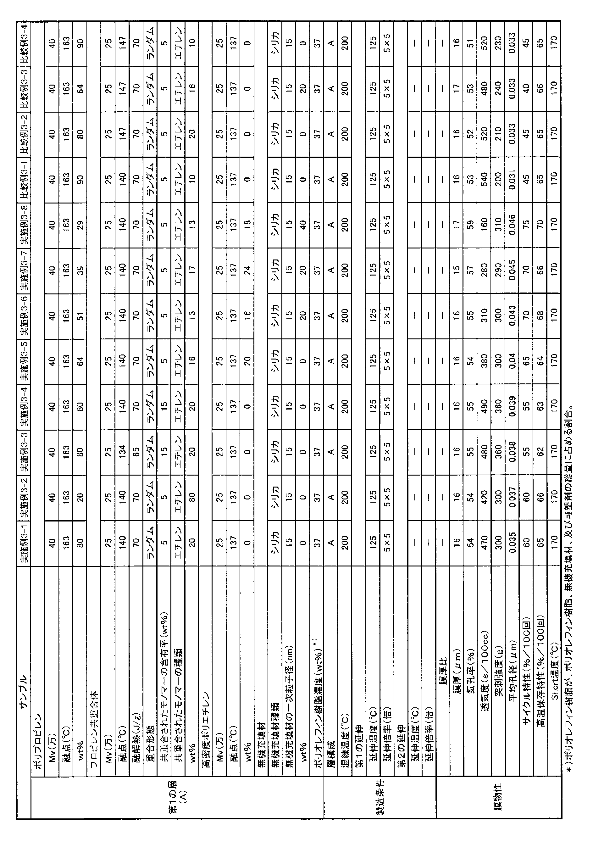

[本実施形態4]
次に、実施例及び比較例を挙げて本実施形態4をより具体的に説明するが、本実施形態4はその要旨を超えない限り、以下の実施例に限定されるものではない。なお、実施例中の物性は以下の方法により測定した。 As is clear from the results of Tables 5 and 6, the microporous membrane of the third embodiment is suitable as a separator that can improve the cycle characteristics of the electricity storage device.
[Embodiment 4]
Next, the present embodiment 4 will be described more specifically with reference to examples and comparative examples, but the present embodiment 4 is not limited to the following examples as long as it does not exceed the gist thereof. In addition, the physical property in an Example was measured with the following method.
粘度平均分子量40万のポリプロピレン(融点163℃)12.9質量部、粘度平均分子量25万、エチレン含有量5質量%のプロピレン-エチレンランダム共重合体(融点140℃)5.7質量部、粘度平均分子量25万の高密度ポリエチレン(融点137℃)8.0質量部、シリカ(吸油量200ml/100g)8質量部、核剤としてビス(p-エチルベンジリデン)ソルビトールを0.3質量部、酸化防止剤としてテトラキス-[メチレン-(3’,5’-ジ-t-ブチル-4’-ヒドロキシフェニル)プロピオネート]メタンを0.2質量部、パラフィン油(松村石油研究所製:P350P、可塑剤密度0.868g/cm3)62質量部を配合し原料を調製した。配合物をバッチ式溶融混練機(東洋精機社製:ラボプラストミル)を用いて200℃・50rpmで10分間混練した。得られた混練物を200℃の加熱プレスで5MPaにて成形し3分間そのまま熱処理をした後、25℃に制御された水冷プレスで5MPaにて冷却し、厚さ500μmのシートとした。これを同時2軸延伸機(東洋精機社製)を用いて5×5倍に125℃で延伸し、その後塩化メチレンでパラフィン油を抽出除去し、乾燥させた。得られたポリエチレン微多孔膜の物性を表7に示す。 [Example 4-1]
12.9 parts by mass of polypropylene (melting point 163 ° C.) having a viscosity average molecular weight of 400,000, 5.7 parts by mass of a propylene-ethylene random copolymer (melting point 140 ° C.) having a viscosity average molecular weight of 250,000 and an ethylene content of 5% by mass, viscosity 8.0 parts by mass of high-density polyethylene (melting point: 137 ° C.) with an average molecular weight of 250,000, 8 parts by mass of silica (oil absorption 200 ml / 100 g), 0.3 parts by mass of bis (p-ethylbenzylidene) sorbitol as a nucleating agent, oxidation 0.2 parts by mass of tetrakis- [methylene- (3 ′, 5′-di-t-butyl-4′-hydroxyphenyl) propionate] methane as an inhibitor, paraffin oil (manufactured by Matsumura Oil Research Institute: P350P, plasticizer) A raw material was prepared by blending 62 parts by mass of a density of 0.868 g / cm 3 . The blend was kneaded for 10 minutes at 200 ° C. and 50 rpm using a batch melt kneader (Toyo Seiki Co., Ltd .: Labo Plast Mill). The obtained kneaded material was molded at 5 MPa with a 200 ° C. hot press and heat treated for 3 minutes as it was, and then cooled at 5 MPa with a water-cooled press controlled at 25 ° C. to obtain a sheet having a thickness of 500 μm. This was stretched 5 × 5 times at 125 ° C. using a simultaneous biaxial stretching machine (manufactured by Toyo Seiki Co., Ltd.), and then the paraffin oil was extracted and removed with methylene chloride and dried. Table 7 shows the physical properties of the obtained polyethylene microporous membrane.
表7に示す条件以外は実施例4-1と同様にしてポリエチレン微多孔膜を得た。得られたポリエチレン微多孔膜の物性を表7に示す。 [Examples 4-2 to 4-6, Comparative examples 4-1 to 4-3]
A polyethylene microporous membrane was obtained in the same manner as in Example 4-1, except for the conditions shown in Table 7. Table 7 shows the physical properties of the obtained polyethylene microporous membrane.
表面層の原料として、粘度平均分子量40万のポリプロピレン(融点163℃)16.3質量部、粘度平均分子量25万、エチレン含有量5質量%のプロピレン-エチレンランダム共重合体(融点140℃、融解熱70J/g)7.2質量部、粘度平均分子量25万の高密度ポリエチレン(融点137℃)10.1質量部、シリカ(吸油量200ml/100g)14.4質量部、核剤としてビス(p-エチルベンジリデン)ソルビトールを0.3質量部、酸化防止剤としてテトラキス-[メチレン-(3’、5’-ジ-t-ブチル-4’-ヒドロキシフェニル)プロピオネート]メタンを0.2質量部、可塑剤として流動パラフィン(松村石油研究所製:P350P)17.3質量部をミキサーで攪拌し原料を調製した。
中間層の原料として、粘度平均分子量25万、融点137℃の高密度ポリエチレン1を14.25質量部、粘度平均分子量70万、融点137℃の高密度ポリエチレン2を14.25質量部、粘度平均分子量40万、融点163℃のポリプロピレン1.5質量部、酸化防止剤としてテトラキス-[メチレン-(3’、5’-ジ-t-ブチル-4’-ヒドロキシフェニル)プロピオネート]メタンを0.2質量部配合し原料を調製した。
各配合物は2台の口径25mm、L/D=48の二軸押出機フィーダーを介して投入した。さらに、表面層には流動パラフィン60質量部、中間層には70質量部をサイドフィードでそれぞれの押出機に注入し、両表面層、中間層の押出量がそれぞれ、1時間当たり4kg、16kgとなるように調整し、200℃、200rpmの条件で混練した後、押出機先端に取り付けた共押出(二種三層)が可能なTダイから220℃の条件で押出した。ただちに、表面温度70℃に制御されたロールに押出し、さらに表面温度25℃に制御されたロールにて冷却させ、厚さ1.4mmのシートを成形した。このシートを同時二軸延伸機で125℃の条件で7×7倍に延伸した後、塩化メチレンに浸漬して、流動パラフィンを抽出除去後乾燥し、テンター延伸機により125℃の条件で横方向に1.5倍延伸した。その後、この延伸シートを132℃で21%幅方向に緩和して熱処理を行い、表面層の二層が同一の組成で、中間層が異なる組成の二種三層構造を有する微多孔膜を得た。得られた微多孔膜の物性を表8に示す。 [Example 4-7]
As raw materials for the surface layer, 16.3 parts by mass of polypropylene (melting point 163 ° C.) having a viscosity average molecular weight of 400,000, propylene-ethylene random copolymer (melting point 140 ° C., melting point) having a viscosity average molecular weight of 250,000 and an ethylene content of 5% by mass Heat 70J / g) 7.2 parts by mass, viscosity average molecular weight 250,000 high density polyethylene (melting point 137 ° C.) 10.1 parts by mass, silica (oil absorption 200 ml / 100 g) 14.4 parts by mass, bis ( 0.3 parts by weight of p-ethylbenzylidene) sorbitol and 0.2 parts by weight of tetrakis- [methylene- (3 ′, 5′-di-t-butyl-4′-hydroxyphenyl) propionate] methane as an antioxidant Then, 17.3 parts by mass of liquid paraffin (manufactured by Matsumura Oil Research Institute: P350P) as a plasticizer was stirred with a mixer to prepare a raw material.
As a raw material for the intermediate layer, 14.25 parts by mass of
Each compound was charged through two twin screw extruder feeders having a diameter of 25 mm and L / D = 48. Furthermore, 60 parts by mass of liquid paraffin was injected into the surface layer, and 70 parts by mass of the intermediate layer was injected into each extruder by side feed, and the extrusion amounts of both the surface layer and the intermediate layer were 4 kg and 16 kg per hour, respectively. The mixture was kneaded under conditions of 200 ° C. and 200 rpm, and then extruded from a T die attached to the tip of the extruder capable of co-extrusion (two types and three layers) at 220 ° C. Immediately, the sheet was extruded into a roll controlled at a surface temperature of 70 ° C., and further cooled by a roll controlled at a surface temperature of 25 ° C. to form a sheet having a thickness of 1.4 mm. The sheet was stretched 7 × 7 times at 125 ° C. with a simultaneous biaxial stretching machine, then dipped in methylene chloride, extracted after removing liquid paraffin, and dried in a transverse direction at 125 ° C. with a tenter stretching machine. The film was stretched 1.5 times. Thereafter, the stretched sheet is relaxed in the width direction by 21% at 132 ° C. and subjected to heat treatment to obtain a microporous membrane having a two-layer / three-layer structure in which the two layers of the surface layer have the same composition and the intermediate layer has a different composition. It was. Table 8 shows the physical properties of the obtained microporous film.
表8に示す条件以外は実施例4-7と同様にしてポリエチレン微多孔膜を得た。得られたポリエチレン微多孔膜の物性を表8に示す。
[実施例4-18]
ポリオレフィン第1微多孔層の原料を粘度平均分子量40万のポリプロピレン(融点163℃)を24.4質量部、粘度平均分子量25万、エチレン含有量5質量%のプロピレン-エチレン共重合体(融点160℃)を1.2質量部、粘度平均分子量25万の高密度ポリエチレン(融点137℃)を5.9質量部、粘度平均分子量1000のポリエチレン(融点120℃)を0.5質量部、平均一次粒径が15nmであるシリカを8質量部とした以外は実施例4-7と同様にして二種三層構造を有する微多孔膜を得た。
得られた積層セパレータはシャットダウン特性に優れていた。 [Examples 4-8 to 4-17, Comparative Examples 4-4 to 4-6]
Except for the conditions shown in Table 8, a polyethylene microporous membrane was obtained in the same manner as in Example 4-7. Table 8 shows the physical properties of the obtained polyethylene microporous membrane.
[Example 4-18]
The raw material of the first polyolefin microporous layer is a polypropylene (melting point 163 ° C.) having a viscosity average molecular weight of 24.4 parts by mass, a propylene-ethylene copolymer having a viscosity average molecular weight of 250,000 and an ethylene content of 5% by mass (melting point 160). ° C) 1.2 parts by mass, 5.9 parts by mass of high density polyethylene (melting point 137 ° C) having a viscosity average molecular weight of 250,000, 0.5 parts by mass of polyethylene having a viscosity average molecular weight of 1000 (melting point 120 ° C), and average primary A microporous membrane having a two-kind-three-layer structure was obtained in the same manner as in Example 4-7, except that 8 parts by mass of silica having a particle size of 15 nm was used.
The obtained laminated separator was excellent in shutdown characteristics.
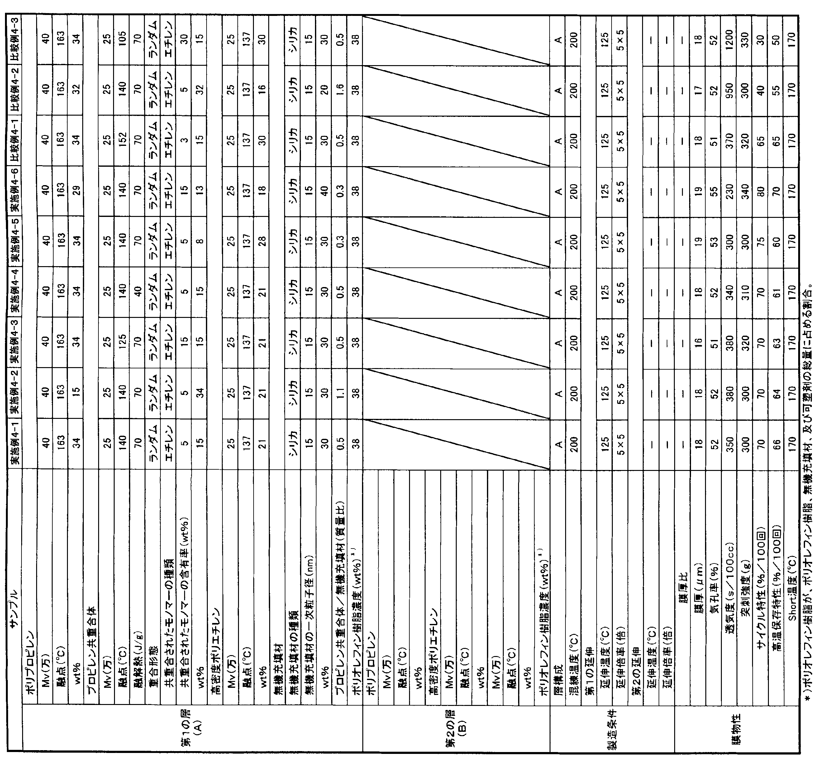
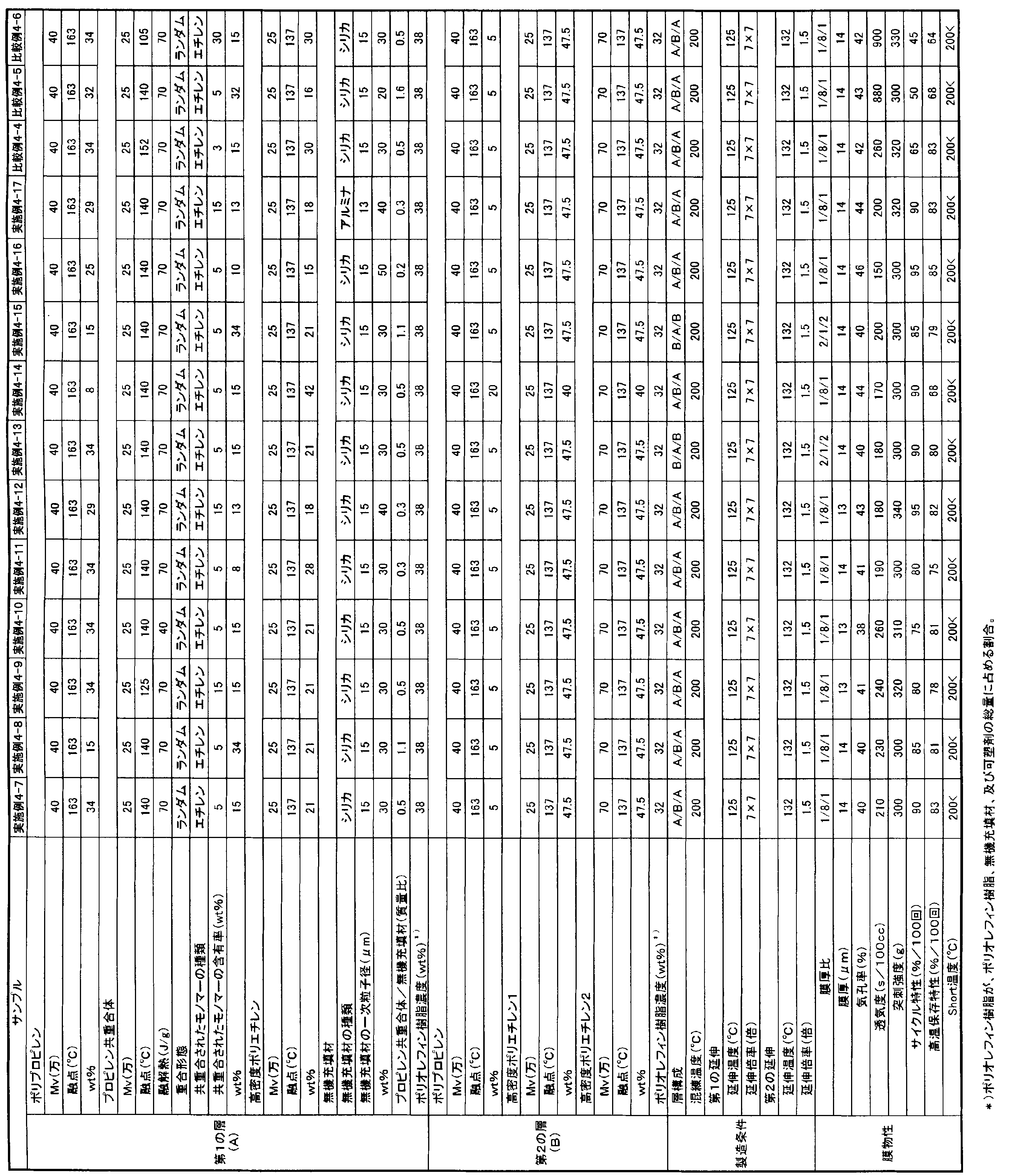
また、本発明によれば、蓄電デバイスのサイクル特性を向上させ得るセパレータとして好適なポリオレフィン微多孔膜が提供される。 ADVANTAGE OF THE INVENTION According to this invention, the separator which balances heat resistance, cycling characteristics, and shutdown characteristics on a high level is provided. Such a separator has industrial applicability particularly as a separator for a lithium ion battery.
Moreover, according to this invention, the polyolefin microporous film suitable as a separator which can improve the cycling characteristics of an electrical storage device is provided.
2A、2B:厚さ10μmのニッケル箔
3A、3B:ガラス板
4:電気抵抗測定装置
5:熱電対
6:温度計
7:データーコレクター
8:オーブン 1:
Claims (15)
- ポリオレフィン第1微多孔層と、前記第1微多孔層に積層され、かつ前記第1微多孔層とは異なるポリオレフィン第2微多孔層とを有し、
前記第1微多孔層と前記第2微多孔層の少なくとも一方が、一次粒子径として1nm以上80nm以下である無機充填材を含有する積層セパレータ。 A polyolefin first microporous layer, and a polyolefin second microporous layer stacked on the first microporous layer and different from the first microporous layer,
A laminated separator in which at least one of the first microporous layer and the second microporous layer contains an inorganic filler having a primary particle diameter of 1 nm to 80 nm. - 前記ポリオレフィン第1微多孔層のポリオレフィン樹脂と無機充填材との総量中に占める無機充填材濃度C1と、前記ポリオレフィン第2微多孔層のポリオレフィン樹脂と無機充填材との総量中に占める無機充填材濃度C2との差が、10質量%以上95質量%以下である請求項1記載の積層セパレータ。 Inorganic filler concentration C1 in the total amount of polyolefin resin and inorganic filler in the first polyolefin microporous layer, and inorganic filler in the total amount of polyolefin resin and inorganic filler in the second polyolefin microporous layer The laminated separator according to claim 1, wherein the difference from the concentration C2 is 10 mass% or more and 95 mass% or less.
- 前記ポリオレフィン第1微多孔層が表面層であり、前記ポリオレフィン第2微多孔層が中間層である少なくとも2種3層構造を有するとともに、
前記ポリオレフィン第1微多孔層は、前記第1微多孔層の構成成分であるポリオレフィン樹脂と無機充填材との総量に対して5~90質量%のポリオレフィン樹脂を含有し、前記ポリオレフィン第2微多孔層は、前記第2微多孔層の構成成分であるポリオレフィン樹脂と無機充填材との総量に対して60~100質量%のポリオレフィン樹脂を含有する、請求項1又は2に記載の積層セパレータ。 The polyolefin first microporous layer is a surface layer, and the polyolefin second microporous layer is an intermediate layer and has at least two kinds and three layers.
The polyolefin first microporous layer contains 5 to 90% by mass of a polyolefin resin based on the total amount of the polyolefin resin and the inorganic filler that are constituents of the first microporous layer, and the polyolefin second microporous layer. The laminated separator according to claim 1 or 2, wherein the layer contains 60 to 100% by mass of a polyolefin resin based on the total amount of the polyolefin resin and the inorganic filler, which are constituent components of the second microporous layer. - ポリプロピレンを50~99質量%、プロピレン-α-オレフィン共重合体を1~50質量%含むポリオレフィン樹脂を主成分として形成され、
前記プロピレン-α-オレフィン共重合体中のα-オレフィン含有率が、1質量%を超えて15質量%以下であるポリオレフィン微多孔膜。 Formed of a polyolefin resin containing 50 to 99% by mass of polypropylene and 1 to 50% by mass of a propylene-α-olefin copolymer as a main component,
A polyolefin microporous membrane having an α-olefin content in the propylene-α-olefin copolymer of more than 1% by mass and 15% by mass or less. - 前記ポリプロピレンと、前記プロピレン-α-オレフィン共重合体との配合比(ポリプロピレン/プロピレン-α-オレフィン共重合体)(質量比)が1.5以上60以下である請求項4記載のポリオレフィン微多孔膜。 5. The microporous polyolefin according to claim 4, wherein a blending ratio (polypropylene / propylene-α-olefin copolymer) (mass ratio) between the polypropylene and the propylene-α-olefin copolymer is 1.5 or more and 60 or less. film.
- (ポリプロピレン)/(プロピレン共重合体)(質量比)が80/20~0/100であるポリプロピレン系樹脂を主成分として含むプロピレン系樹脂組成物にて形成され、
前記プロピレン共重合体の融点が120℃以上145℃以下であることを特徴とするポリオレフィン微多孔膜。 (Polypropylene) / (propylene copolymer) (mass ratio) is formed of a propylene resin composition containing as a main component a polypropylene resin having a mass ratio of 80/20 to 0/100,
A polyolefin microporous membrane, wherein the propylene copolymer has a melting point of 120 ° C or higher and 145 ° C or lower. - (ポリプロピレン)/(プロピレン共重合体)(質量比)が90/10~0/100であるポリプロピレン系樹脂20~95質量%と、無機充填材5~80質量%とを含むポリプロピレン系樹脂組成物にて形成され、
前記プロピレン共重合体の融点は110℃~150℃であり、
(プロピレン共重合体)/(無機充填材)(質量比)が0.1/1~1.5/1である
ことを特徴とするポリオレフィン微多孔膜。 (Polypropylene) / (Propylene copolymer) (Mass ratio) Polypropylene resin composition comprising 20 to 95% by mass of a polypropylene resin having a ratio of 90/10 to 0/100 and 5 to 80% by mass of an inorganic filler. Formed with
The melting point of the propylene copolymer is 110 ° C. to 150 ° C.,
A polyolefin microporous membrane, wherein (propylene copolymer) / (inorganic filler) (mass ratio) is 0.1 / 1 to 1.5 / 1. - 前記無機充填材が、シリカ、アルミナ、及びチタニアからなる群から選ばれるいずれか1種以上である請求項1~3、又は7のいずれかに記載のポリオレフィン微多孔膜。 The polyolefin microporous membrane according to any one of claims 1 to 3, or 7, wherein the inorganic filler is at least one selected from the group consisting of silica, alumina, and titania.
- 請求項4~7のいずれか1項記載のポリオレフィン微多孔膜の少なくとも一方の面に、前記ポリオレフィン微多孔膜とは異なる他のポリオレフィン微多孔膜が積層された積層ポリオレフィン微多孔膜。 A laminated polyolefin microporous membrane in which another polyolefin microporous membrane different from the polyolefin microporous membrane is laminated on at least one surface of the polyolefin microporous membrane according to any one of claims 4 to 7.
- 請求項1~3のいずれか1項に記載の、ポリオレフィン第1微多孔層と、前記第1微多孔層に積層され、かつ前記第1微多孔層とは異なるポリオレフィン第2微多孔層とを有する積層セパレータの製造方法であって、
(1)ポリオレフィンと可塑剤、及び、必要に応じて無機充填材を混練して混練物を形成する混練工程、
(2)前記混練工程の後、所望の層構成に応じて前記混練物をシート状に押出し、冷却固化させ、シート状成形体に加工するシート成形工程、
(3)前記成形工程の後、前記シート状成形体を面倍率が20倍以上200倍以下で二軸延伸し、延伸物を形成する延伸工程、
(4)前記延伸工程の後、前記延伸物から可塑剤を抽出して多孔体を形成する多孔体形成工程、
(5)前記多孔体形成工程の後、前記多孔体に対し、前記ポリオレフィン樹脂の融点以下にて熱処理を行い、幅方向に延伸を行う熱処理工程、
を有し、
前記第1微多孔層と前記第2微多孔層の少なくとも一方が、一次粒子径として1nm以上80nm以下である無機充填剤を含有することを特徴とする製造方法。 The polyolefin first microporous layer according to any one of claims 1 to 3, and a polyolefin second microporous layer laminated on the first microporous layer and different from the first microporous layer. A method for producing a laminated separator comprising:
(1) a kneading step of kneading a polyolefin, a plasticizer, and, if necessary, an inorganic filler to form a kneaded product,
(2) After the kneading step, the kneaded product is extruded into a sheet shape according to a desired layer configuration, cooled and solidified, and processed into a sheet-like molded body,
(3) After the forming step, the sheet-like formed body is biaxially stretched at a surface magnification of 20 times to 200 times to form a stretched product,
(4) After the stretching step, a porous body forming step of forming a porous body by extracting a plasticizer from the stretched product,
(5) After the porous body forming step, the porous body is heat-treated at a temperature equal to or lower than the melting point of the polyolefin resin, and stretched in the width direction.
Have
At least one of the first microporous layer and the second microporous layer contains an inorganic filler having a primary particle diameter of 1 nm or more and 80 nm or less. - 請求項4又は5に記載のポリオレフィン微多孔膜の製造方法であって、
(1)ポリプロピレンを50~99質量%、プロピレン共重合体を1~50質量%含むポリオレフィン樹脂と可塑剤を混練して混練物を形成する混練工程、
(2)前記混練工程の後、前記混練物をシート状に押出し、冷却固化させ、シート状成形体に加工するシート成形工程、
(3)前記成形工程の後、前記シート状成形体を面倍率が20倍以上200倍以下で二軸延伸し、延伸物を形成する延伸工程、
(4)前記延伸工程の後、前記延伸物から可塑剤を抽出して多孔体を形成する多孔体形成工程、
(5)前記多孔体形成工程の後、前記多孔体に対し、前記ポリオレフィン樹脂の融点以下にて熱処理を行い、幅方向に延伸を行う熱処理工程、
を有し、
前記プロピレン-α-オレフィン共重合体中のα-オレフィン含有率が、1質量%を超えて15質量%以下であることを特徴とする製造方法。 A method for producing a polyolefin microporous membrane according to claim 4 or 5,
(1) a kneading step of kneading a polyolefin resin containing 50 to 99% by mass of polypropylene and 1 to 50% by mass of a propylene copolymer and a plasticizer to form a kneaded product;
(2) After the kneading step, the kneaded product is extruded into a sheet shape, cooled and solidified, and processed into a sheet-shaped formed body,
(3) After the forming step, the sheet-like formed body is biaxially stretched at a surface magnification of 20 times to 200 times to form a stretched product,
(4) After the stretching step, a porous body forming step of forming a porous body by extracting a plasticizer from the stretched product,
(5) After the porous body forming step, the porous body is heat-treated at a temperature equal to or lower than the melting point of the polyolefin resin, and stretched in the width direction.
Have
A production method, wherein the propylene-α-olefin copolymer has an α-olefin content of more than 1% by mass and 15% by mass or less. - 請求項6に記載のポリオレフィン微多孔膜の製造方法であって、
(1)(ポリプロピレン)/(プロピレン共重合体)(質量比)が80/20~0/100であるポリプロピレン系樹脂組成物と可塑剤を混練して混練物を形成する混練工程、
(2)前記混練工程の後、前記混練物をシート状に押出し、冷却固化させ、シート状成形体に加工するシート成形工程、
(3)前記成形工程の後、前記シート状成形体を面倍率が20倍以上200倍以下で二軸延伸し、延伸物を形成する延伸工程、
(4)前記延伸工程の後、前記延伸物から可塑剤を抽出して多孔体を形成する多孔体形成工程、
(5)前記多孔体形成工程の後、前記多孔体に対し、前記ポリオレフィン樹脂の融点以下にて熱処理を行い、幅方向に延伸を行う熱処理工程、
を有し、
前記プロピレン共重合体の融点が120℃以上145℃以下であることを特徴とする製造方法。 A method for producing a polyolefin microporous membrane according to claim 6,
(1) a kneading step of kneading a polypropylene resin composition having a (polypropylene) / (propylene copolymer) (mass ratio) of 80/20 to 0/100 and a plasticizer to form a kneaded product;
(2) After the kneading step, the kneaded product is extruded into a sheet shape, cooled and solidified, and processed into a sheet-shaped formed body,
(3) After the forming step, the sheet-like formed body is biaxially stretched at a surface magnification of 20 times to 200 times to form a stretched product,
(4) After the stretching step, a porous body forming step of forming a porous body by extracting a plasticizer from the stretched product,
(5) After the porous body forming step, the porous body is heat-treated at a temperature equal to or lower than the melting point of the polyolefin resin, and stretched in the width direction.
Have
The method for producing, wherein the propylene copolymer has a melting point of 120 ° C or higher and 145 ° C or lower. - 請求項7に記載のポリオレフィン微多孔膜の製造方法であって、
(1)(ポリプロピレン)/(プロピレン共重合体)(質量比)が90/10~0/100であるポリプロピレン系樹脂20~95質量%と、無機充填材5~80質量%とを含むポリプロピレン系樹脂組成物と可塑剤を混練して混練物を形成する混練工程、
(2)前記混練工程の後、前記混練物をシート状に押出し、冷却固化させ、シート状成形体に加工するシート成形工程、
(3)前記成形工程の後、前記シート状成形体を面倍率が20倍以上200倍以下で二軸延伸し、延伸物を形成する延伸工程、
(4)前記延伸工程の後、前記延伸物から可塑剤を抽出して多孔体を形成する多孔体形成工程、
(5)前記多孔体形成工程の後、前記多孔体に対し、前記ポリオレフィン樹脂の融点以下にて熱処理を行い、幅方向に延伸を行う熱処理工程、
を有し、
前記プロピレン共重合体の融点は110℃~150℃であり、
(プロピレン共重合体)/(無機充填材)(質量比)が0.1/1~1.5/1である
ことを特徴とする製造方法。 A method for producing a polyolefin microporous membrane according to claim 7,
(1) Polypropylene containing 20 to 95% by weight of polypropylene resin having (polypropylene) / (propylene copolymer) (mass ratio) of 90/10 to 0/100 and 5 to 80% by weight of an inorganic filler A kneading step of kneading the resin composition and the plasticizer to form a kneaded product,
(2) After the kneading step, the kneaded product is extruded into a sheet shape, cooled and solidified, and processed into a sheet-shaped formed body,
(3) After the forming step, the sheet-like formed body is biaxially stretched at a surface magnification of 20 times to 200 times to form a stretched product,
(4) After the stretching step, a porous body forming step of forming a porous body by extracting a plasticizer from the stretched product,
(5) After the porous body forming step, the porous body is heat-treated at a temperature equal to or lower than the melting point of the polyolefin resin, and stretched in the width direction.
Have
The melting point of the propylene copolymer is 110 ° C. to 150 ° C.,
(Propylene copolymer) / (Inorganic filler) (mass ratio) is 0.1 / 1 to 1.5 / 1. - 前記プロピレン共重合体の融解熱が60J/g以上であることを特徴とする請求項11~13のいずれかに記載の製造方法。 The method according to any one of claims 11 to 13, wherein the heat of fusion of the propylene copolymer is 60 J / g or more.
- 前記混練物が、更に粘度平均分子量800以上1万以下の低分子量樹脂を含む請求項10~14のいずれかに記載の製造方法。
The production method according to any one of claims 10 to 14, wherein the kneaded material further contains a low molecular weight resin having a viscosity average molecular weight of 800 or more and 10,000 or less.
Priority Applications (17)
| Application Number | Priority Date | Filing Date | Title |
|---|---|---|---|
| KR1020167025429A KR20160111547A (en) | 2009-03-09 | 2010-03-09 | Laminated separator, polyolefin micro-porous membrane, and separator for electricity storage device |
| EP18168699.9A EP3376564B1 (en) | 2009-03-09 | 2010-03-09 | Use of a laminated polyolefin microporous membrane as a separator for electricity storage devices |
| KR1020177016866A KR102087241B1 (en) | 2009-03-09 | 2010-03-09 | Laminated separator, polyolefin micro-porous membrane, and separator for electricity storage device |
| KR1020187025453A KR102087243B1 (en) | 2009-03-09 | 2010-03-09 | Laminated separator, polyolefin micro-porous membrane, and separator for electricity storage device |
| KR1020117021064A KR101287667B1 (en) | 2009-03-09 | 2010-03-09 | Laminated separator, polyolefin micro-porous membrane, and separator for electricity storage device |
| KR1020137002712A KR101592075B1 (en) | 2009-03-09 | 2010-03-09 | Laminated separator, polyolefin micro-porous membrane, and separator for electricity storage device |
| CN201080011547.1A CN102349177B (en) | 2009-03-09 | 2010-03-09 | Stacked separator, polyolefin micro porous polyolefin membrane and electric energy storage device separator |
| CN201410003616.4A CN103788483B (en) | 2009-03-09 | 2010-03-09 | Polyolefin micro porous polyolefin membrane, stacking polyolefin micro porous polyolefin membrane, the manufacture method of polyolefin micro porous polyolefin membrane |
| EP10750830.1A EP2408043B2 (en) | 2009-03-09 | 2010-03-09 | Laminated separator, polyolefin microporous membrane, and separator for electricity storage device |
| PL18168699T PL3376564T3 (en) | 2009-03-09 | 2010-03-09 | Use of a laminated polyolefin microporous membrane as a separator for electricity storage devices |
| JP2011503827A JP5369171B2 (en) | 2009-03-09 | 2010-03-09 | Laminated separator and method for producing the same |
| US13/255,424 US9356275B2 (en) | 2009-03-09 | 2010-03-09 | Laminated separator including inorganic particle and polyolefin layer for electricity storage device |
| KR1020137029222A KR20130127558A (en) | 2009-03-09 | 2010-03-09 | Laminated separator, polyolefin micro-porous membrane, and separator for electricity storage device |
| US14/302,040 US9853272B2 (en) | 2009-03-09 | 2014-06-11 | Laminated polyolefin microporous membrane including propylene-α-olefin copolymer and method of producing the same |
| US14/302,090 US9966583B2 (en) | 2009-03-09 | 2014-06-11 | Laminated polyolefin microporous membrane including propylene copolymer and method of producing the same |
| US14/302,213 US9882190B2 (en) | 2009-03-09 | 2014-06-11 | Laminated polymicroporous membrane including propylene copolymer and method of producing the same |
| US15/147,399 US10680223B2 (en) | 2009-03-09 | 2016-05-05 | Laminated separator, polyolefin microporous membrane, and separator for electricity storage device |
Applications Claiming Priority (12)
| Application Number | Priority Date | Filing Date | Title |
|---|---|---|---|
| JP2009054795 | 2009-03-09 | ||
| JP2009-054795 | 2009-03-09 | ||
| JP2009064533 | 2009-03-17 | ||
| JP2009-064533 | 2009-03-17 | ||
| JP2009-280488 | 2009-12-10 | ||
| JP2009280486 | 2009-12-10 | ||
| JP2009280488 | 2009-12-10 | ||
| JP2009-280486 | 2009-12-10 | ||
| JP2010-021859 | 2010-02-03 | ||
| JP2010-022481 | 2010-02-03 | ||
| JP2010022481 | 2010-02-03 | ||
| JP2010021859 | 2010-02-03 |
Related Child Applications (4)
| Application Number | Title | Priority Date | Filing Date |
|---|---|---|---|
| US13/255,424 A-371-Of-International US9356275B2 (en) | 2009-03-09 | 2010-03-09 | Laminated separator including inorganic particle and polyolefin layer for electricity storage device |
| US14/302,213 Division US9882190B2 (en) | 2009-03-09 | 2014-06-11 | Laminated polymicroporous membrane including propylene copolymer and method of producing the same |
| US14/302,090 Division US9966583B2 (en) | 2009-03-09 | 2014-06-11 | Laminated polyolefin microporous membrane including propylene copolymer and method of producing the same |
| US14/302,040 Division US9853272B2 (en) | 2009-03-09 | 2014-06-11 | Laminated polyolefin microporous membrane including propylene-α-olefin copolymer and method of producing the same |
Publications (1)
| Publication Number | Publication Date |
|---|---|
| WO2010104077A1 true WO2010104077A1 (en) | 2010-09-16 |
Family
ID=42728366
Family Applications (1)
| Application Number | Title | Priority Date | Filing Date |
|---|---|---|---|
| PCT/JP2010/053899 WO2010104077A1 (en) | 2009-03-09 | 2010-03-09 | Laminated separator, polyolefin micro-porous membrane, and separator for electricity storage device |
Country Status (8)
| Country | Link |
|---|---|
| US (5) | US9356275B2 (en) |
| EP (5) | EP2672546B1 (en) |
| JP (6) | JP5369171B2 (en) |
| KR (6) | KR20160111547A (en) |
| CN (5) | CN105150655B (en) |
| HU (4) | HUE037810T2 (en) |
| PL (4) | PL3376564T3 (en) |
| WO (1) | WO2010104077A1 (en) |
Cited By (8)
| Publication number | Priority date | Publication date | Assignee | Title |
|---|---|---|---|---|
| JP2012092287A (en) * | 2010-09-30 | 2012-05-17 | Sekisui Chem Co Ltd | Propylene-based resin micropore film and method of manufacturing the same, and separator for lithium ion battery and lithium ion battery |
| JP2013054966A (en) * | 2011-09-05 | 2013-03-21 | Nissan Motor Co Ltd | Separator with heat resistant insulation layer |
| CN103178228A (en) * | 2011-12-21 | 2013-06-26 | 三星Total株式会社 | Lithium ion battery separator with shutdown property |
| US20130323570A1 (en) * | 2011-02-28 | 2013-12-05 | Sanyo Electric Co., Ltd. | Nonaqueous electrolyte secondary battery |
| WO2014030507A1 (en) * | 2012-08-23 | 2014-02-27 | Jnc株式会社 | Composite porous film having excellent heat resistance |
| JP2015514812A (en) * | 2012-02-08 | 2015-05-21 | エスケー イノベーション カンパニー リミテッド | Polyolefin composite microporous membrane excellent in heat resistance and stability and method for producing the same |
| JP2016143640A (en) * | 2015-02-05 | 2016-08-08 | 東レバッテリーセパレータフィルム株式会社 | Manufacturing method of battery separator and wound body of battery separator |
| JPWO2019235112A1 (en) * | 2018-06-08 | 2021-02-25 | 旭化成株式会社 | Multi-layer separator |
Families Citing this family (61)
| Publication number | Priority date | Publication date | Assignee | Title |
|---|---|---|---|---|
| CN105150655B (en) | 2009-03-09 | 2018-09-14 | 旭化成株式会社 | Separator and its manufacturing method is laminated |
| WO2012034042A2 (en) | 2010-09-09 | 2012-03-15 | California Institute Of Technology | Electrochemical energy storage systems and methods |
| US9379368B2 (en) | 2011-07-11 | 2016-06-28 | California Institute Of Technology | Electrochemical systems with electronically conductive layers |
| KR101950975B1 (en) | 2011-07-11 | 2019-02-21 | 캘리포니아 인스티튜트 오브 테크놀로지 | Novel separators for electrochemical systems |
| US9627672B2 (en) * | 2012-03-28 | 2017-04-18 | Asahi Kasei E-Materials Corporation | Separator for nonaqueous electrolyte batteries containing a porous membrane |
| US9520580B2 (en) | 2012-05-08 | 2016-12-13 | Battelle Memorial Institute | Multifunctional cell for structural applications |
| US20150086707A1 (en) * | 2012-05-17 | 2015-03-26 | Toyota Jidosha Kabushiki Kaisha | Method for manufacturing a battery |
| KR101460179B1 (en) | 2012-11-28 | 2014-11-10 | 에스케이씨앤씨 주식회사 | Method for Temporary Payment Card Set-up and Mobile Device using the same |
| KR102035375B1 (en) | 2013-10-15 | 2019-10-22 | 가부시키가이샤 무라타 세이사쿠쇼 | Battery, battery pack, electronic device, electric vehicle, electric storage device, and power system |
| CN111466810B (en) * | 2013-10-18 | 2022-10-11 | 赛尔格有限责任公司 | Microporous membrane wipe |
| WO2015074037A2 (en) | 2013-11-18 | 2015-05-21 | California Institute Of Technology | Separator enclosures for electrodes and electrochemical cells |
| US10714724B2 (en) | 2013-11-18 | 2020-07-14 | California Institute Of Technology | Membranes for electrochemical cells |
| CN106103045B (en) * | 2014-03-28 | 2019-05-21 | 东丽株式会社 | Biaxially oriented polypropylene film |
| KR101962418B1 (en) | 2014-06-24 | 2019-03-27 | 제일모직 주식회사 | Separator, manufacturing the separator and battery using thereof |
| EP3183290A4 (en) | 2014-08-21 | 2018-09-05 | Yen, William Winchin | Microporous sheet product and methods for making and using the same |
| KR101910222B1 (en) * | 2014-10-20 | 2018-10-19 | 주식회사 엘지화학 | A multi-layered separator having high heat resistance property for a secondary battery |
| CN107078259B (en) | 2014-11-05 | 2021-01-08 | W·W·严 | Microporous sheet products and methods of making and using the same |
| US10829600B2 (en) * | 2014-11-05 | 2020-11-10 | William Winchin Yen | Microporous sheet product and methods for making and using the same |
| CN104393215B (en) * | 2014-12-01 | 2017-01-04 | 天津工业大学 | Multi-layer porous battery diaphragm of component ratio continually varying in gradient and preparation method thereof |
| EP3239223A4 (en) * | 2014-12-26 | 2017-11-29 | Toray Industries, Inc. | Polyolefin microporous membrane, production method therefor, and battery separator |
| JP6642214B2 (en) * | 2015-04-01 | 2020-02-05 | 三菱ケミカル株式会社 | Laminated porous film, battery separator, and battery |
| FR3034771B1 (en) * | 2015-04-13 | 2019-04-19 | Hutchinson | THERMAL AND / OR ELECTRICALLY CONDUCTIVE MATERIALS AND METHOD FOR THE PREPARATION THEREOF |
| FR3034775B1 (en) | 2015-04-13 | 2018-09-28 | Hutchinson | MATERIAL FOR THERMAL STORAGE |
| JP6627616B2 (en) * | 2015-04-15 | 2020-01-08 | 三菱ケミカル株式会社 | Laminated porous film, battery separator, and battery |
| JP2018518799A (en) * | 2015-05-08 | 2018-07-12 | セルガード エルエルシー | Improved, coated or treated microporous battery separator, rechargeable lithium battery, system, and related methods of manufacture and / or use |
| CN105118946B (en) * | 2015-09-13 | 2018-03-20 | 中南大学 | A kind of preparation method of lithium ion battery separator |
| JP6758809B2 (en) | 2015-09-29 | 2020-09-23 | 日東電工株式会社 | A method for producing a porous gel-containing liquid, a method for producing a porous gel-containing liquid, a method for producing a high void layer, a method for producing a high porosity porous body, and a method for producing a laminated film roll. |
| US20180311930A1 (en) * | 2015-10-30 | 2018-11-01 | Jnc Corporation | Organic-inorganic composite membrane excellent in smoothness and multi-layer heat resistant separator material using same |
| CN105445313A (en) * | 2015-11-30 | 2016-03-30 | 深圳市星源材质科技股份有限公司 | Method for detecting thermal stability of battery separator |
| WO2017096258A1 (en) | 2015-12-02 | 2017-06-08 | California Institute Of Technology | Three-dimensional ion transport networks and current collectors for electrochemical cells |
| KR102121252B1 (en) * | 2015-12-04 | 2020-06-10 | 도레이 카부시키가이샤 | Battery separator and method of manufacturing same |
| TWI594635B (en) * | 2016-01-14 | 2017-08-01 | 瑞昱半導體股份有限公司 | Method for generating target gain value of wide dynamic range operation |
| TWI770003B (en) * | 2016-04-27 | 2022-07-11 | 日商東麗股份有限公司 | Polyolefin microporous membrane and method for producing the same, separator for battery and method for producing the same |
| US11316231B2 (en) | 2016-09-02 | 2022-04-26 | Daramic, Llc | Battery separators with improved conductance, improved batteries, systems, and related methods |
| US10707531B1 (en) | 2016-09-27 | 2020-07-07 | New Dominion Enterprises Inc. | All-inorganic solvents for electrolytes |
| KR101976659B1 (en) | 2016-12-12 | 2019-05-09 | 삼성에스디아이 주식회사 | Photosensitive resin composition, photosensitive resin layer using same and color filter |
| JP6472822B2 (en) | 2017-03-03 | 2019-02-20 | 住友化学株式会社 | Nonaqueous electrolyte secondary battery separator |
| JP7055663B2 (en) | 2017-03-03 | 2022-04-18 | 住友化学株式会社 | Film manufacturing method, separator manufacturing method and plasticizer manufacturing method |
| JP6543291B2 (en) | 2017-03-03 | 2019-07-10 | 住友化学株式会社 | Separator for non-aqueous electrolyte secondary battery |
| KR102299856B1 (en) | 2017-03-07 | 2021-09-07 | 삼성에스디아이 주식회사 | Porous film, separator and electrochemical battery including the same |
| CN106981608B (en) * | 2017-05-08 | 2021-06-11 | 深圳市星源材质科技股份有限公司 | Preparation method of multilayer microporous membrane for lithium ion battery |
| KR102290094B1 (en) * | 2017-05-26 | 2021-08-18 | 아사히 가세이 가부시키가이샤 | Polyolefin microporous membrane, separator for power storage device, and power storage device |
| JP6953991B2 (en) * | 2017-10-18 | 2021-10-27 | トヨタ自動車株式会社 | Separators, non-aqueous electrolyte secondary batteries, and methods for manufacturing separators |
| KR102142351B1 (en) * | 2017-11-10 | 2020-08-07 | 아사히 가세이 가부시키가이샤 | Separator for power storage device, and power storage device |
| JP7032180B2 (en) | 2018-03-07 | 2022-03-08 | トヨタ自動車株式会社 | Batteries and their manufacturing methods |
| JP6598911B2 (en) * | 2018-03-22 | 2019-10-30 | 旭化成株式会社 | Manufacturing method of polyolefin microporous membrane, battery separator, and non-aqueous electrolyte secondary battery |
| CN109786632A (en) * | 2018-11-23 | 2019-05-21 | 天津力神电池股份有限公司 | A kind of high thermal conductivity composite diaphragm and preparation method thereof |
| JP7235486B2 (en) * | 2018-11-28 | 2023-03-08 | 旭化成株式会社 | Polyolefin microporous membrane |
| EP3950305A4 (en) * | 2019-03-27 | 2022-06-29 | Asahi Kasei Kabushiki Kaisha | Separator for power storage device |
| EP3920299B1 (en) * | 2019-05-17 | 2023-05-03 | Teijin Limited | Separator for non-aqueous secondary battery, method for producing same, and non-aqueous secondary battery |
| EP3998155B1 (en) * | 2019-07-10 | 2024-03-27 | Asahi Kasei Kabushiki Kaisha | Multilayer porous membrane |
| EP4055658A1 (en) | 2019-11-05 | 2022-09-14 | Creonia Cells GmbH | Method for manufacturing a porous film |
| CN110931692A (en) * | 2019-12-08 | 2020-03-27 | 重庆云天化纽米科技股份有限公司 | Polyolefin diaphragm and preparation method and application thereof |
| KR20220114585A (en) * | 2019-12-09 | 2022-08-17 | 다라믹 엘엘씨 | Improved lead-acid battery separator and battery comprising same |
| JP2021091896A (en) * | 2019-12-10 | 2021-06-17 | 旭化成株式会社 | Polyethylene resin composition |
| CN111691069B (en) * | 2020-05-18 | 2021-10-08 | 苏州大学 | Puncture-resistant fiber composite membrane and preparation method thereof |
| JP7357161B2 (en) * | 2020-05-28 | 2023-10-05 | 旭化成株式会社 | Separator for energy storage devices |
| CN114512767B (en) * | 2020-11-16 | 2022-11-15 | 青岛蓝科途膜材料有限公司 | Lithium ion battery diaphragm, preparation method thereof and lithium ion battery prepared from diaphragm |
| EP4023436A1 (en) | 2020-12-29 | 2022-07-06 | Renata AG | Multilayer separator for a battery |
| CN113921992A (en) * | 2021-09-16 | 2022-01-11 | 河北金力新能源科技股份有限公司 | High-heat-resistance lithium battery diaphragm and preparation method and application thereof |
| JP7079536B1 (en) * | 2021-11-25 | 2022-06-02 | 株式会社Tbm | Inorganic substance powder-filled resin composition and molded product |
Citations (11)
| Publication number | Priority date | Publication date | Assignee | Title |
|---|---|---|---|---|
| JPS63243146A (en) | 1987-03-30 | 1988-10-11 | Toray Ind Inc | Microporous polypropylene film |
| JPH09180699A (en) * | 1995-12-22 | 1997-07-11 | Asahi Chem Ind Co Ltd | Micro-porous film for nonaqueous solvent battery separator |
| JPH1180395A (en) | 1997-09-09 | 1999-03-26 | Nitto Denko Corp | Porous film and separator for nonaqueous electrolyte cell or battery |
| JPH11199692A (en) * | 1998-01-07 | 1999-07-27 | Asahi Chem Ind Co Ltd | Production of multilayer microporous film |
| JPH11322989A (en) * | 1998-05-19 | 1999-11-26 | Asahi Chem Ind Co Ltd | Polyolefin-made microporous film for battery separator |
| JP2001266828A (en) | 2000-03-17 | 2001-09-28 | Nippon Muki Co Ltd | Separator for non-aqueous electrolyte battery |
| WO2006038532A1 (en) * | 2004-10-01 | 2006-04-13 | Asahi Kasei Chemicals Corporation | Polyolefin microporous membrane |
| JP4049416B2 (en) | 1997-08-12 | 2008-02-20 | 三菱化学株式会社 | Polyethylene resin porous film and method for producing the same |
| WO2008035674A1 (en) * | 2006-09-20 | 2008-03-27 | Asahi Kasei Chemicals Corporation | Polyolefin microporous membrane and separator for nonaqueous electrolyte battery |
| JP2008254288A (en) * | 2007-04-04 | 2008-10-23 | Asahi Kasei Chemicals Corp | Composite microporous membrane, separator for battery, and method of manufacturing composite microporous membrane |
| JP2009185093A (en) * | 2008-02-01 | 2009-08-20 | Asahi Kasei E-Materials Corp | Polyolefin microporous film |
Family Cites Families (56)
| Publication number | Priority date | Publication date | Assignee | Title |
|---|---|---|---|---|
| GB1051320A (en) | 1964-01-13 | 1966-12-14 | W.R. Grace & Co. | Micro-porous polyethylene and a process for the manufacture thereof |
| US3536796A (en) | 1967-11-29 | 1970-10-27 | Grace W R & Co | Process for reducing shrinkage in preparing porous plastic sheet |
| US4650730A (en) | 1985-05-16 | 1987-03-17 | W. R. Grace & Co. | Battery separator |
| JPS61276544A (en) | 1985-05-31 | 1986-12-06 | 株式会社東芝 | Tomographic apparatus |
| JPS63108041A (en) | 1986-06-12 | 1988-05-12 | Tokuyama Soda Co Ltd | Microporous film and production thereof |
| JPH06101322B2 (en) | 1986-08-01 | 1994-12-12 | 松下電器産業株式会社 | Organic electrolyte battery |
| US5176953A (en) | 1990-12-21 | 1993-01-05 | Amoco Corporation | Oriented polymeric microporous films |
| US5169712A (en) | 1991-08-23 | 1992-12-08 | Amoco Corporation | Porous film composites |
| US5491188A (en) | 1993-05-20 | 1996-02-13 | New Japan Chemical Co., Ltd. | Porous stretched article of polypropylene-based resin and process for its preparation |
| JPH0820659A (en) | 1994-07-08 | 1996-01-23 | Daicel Chem Ind Ltd | Microporous membrane, its production and separator for non-aqueous electrolyte solution cell |
| US5910136A (en) | 1996-12-30 | 1999-06-08 | Kimberly-Clark Worldwide, Inc. | Oriented polymeric microporous films with flexible polyolefins |
| US6072005A (en) | 1997-10-31 | 2000-06-06 | Kimberly-Clark Worldwide, Inc. | Breathable films and process for producing them |
| JPH11195409A (en) | 1998-01-06 | 1999-07-21 | Ube Ind Ltd | Porous film and separator for battery |
| US6180280B1 (en) | 1998-03-12 | 2001-01-30 | Celgard Inc. | Trilayer battery separator |
| US6080507A (en) | 1998-04-13 | 2000-06-27 | Celgard Inc. | Trilayer battery separator |
| JP4387517B2 (en) | 1998-10-21 | 2009-12-16 | 三井化学株式会社 | Soft transparent syndiotactic polypropylene composition |
| JP2000215871A (en) * | 1998-11-16 | 2000-08-04 | Kuraray Co Ltd | Battery separator and its manufacture |
| JP2000173574A (en) | 1998-12-04 | 2000-06-23 | Mitsubishi Paper Mills Ltd | Manufacture of non-aqueous electrolyte battery |
| US6277514B1 (en) † | 1998-12-17 | 2001-08-21 | Moltech Corporation | Protective coating for separators for electrochemical cells |
| JP3471255B2 (en) * | 1999-06-21 | 2003-12-02 | 大和紡績株式会社 | Nonwoven fabric for battery separator and battery using the same |
| US6432586B1 (en) | 2000-04-10 | 2002-08-13 | Celgard Inc. | Separator for a high energy rechargeable lithium battery |
| JP4158004B2 (en) | 2000-06-02 | 2008-10-01 | 新日本理化株式会社 | Porous polypropylene film, method for producing the same, and absorbent article using the film |
| US7138207B2 (en) | 2001-04-20 | 2006-11-21 | Sony Corporation | Non-aqueous electrolyte secondary cell |
| JP4931163B2 (en) * | 2001-04-24 | 2012-05-16 | 旭化成イーマテリアルズ株式会社 | Polyolefin microporous membrane |
| JP2003238720A (en) | 2002-02-20 | 2003-08-27 | Asahi Kasei Corp | Polyolefinic porous membrane |
| JP2003327731A (en) * | 2002-05-09 | 2003-11-19 | Chisso Corp | Polyolefin resin porous membrane |
| JP2004204154A (en) * | 2002-12-26 | 2004-07-22 | Sekisui Chem Co Ltd | Crosslinked polyolefin resin foam and production method thereof |
| CN1860627B (en) | 2003-08-06 | 2011-01-26 | 三菱化学株式会社 | Nonaqueous electrolyte solution secondary battery separator and nonaqueous electrolyte solution secondary battery using the same |
| JP4984372B2 (en) | 2003-08-06 | 2012-07-25 | 三菱化学株式会社 | Nonaqueous electrolyte secondary battery separator and nonaqueous electrolyte secondary battery using the same |
| DE10348876B4 (en) * | 2003-10-21 | 2014-04-03 | Jnc Corporation | Porous polyolefin membrane |
| JP4186798B2 (en) * | 2003-11-14 | 2008-11-26 | チッソ株式会社 | Multilayer porous membrane made of polyolefin resin |
| EP1698656B2 (en) | 2003-12-24 | 2017-04-26 | Asahi Kasei Kabushiki Kaisha | Microporous membrane made from polyolefin |
| JP5052135B2 (en) * | 2004-08-30 | 2012-10-17 | 旭化成イーマテリアルズ株式会社 | Polyolefin microporous membrane and battery separator |
| US20060088769A1 (en) | 2004-10-22 | 2006-04-27 | Celgard Llc | Battery separator with Z-direction stability |
| JP4867185B2 (en) | 2005-03-29 | 2012-02-01 | 住友化学株式会社 | Method for producing porous film and porous film |
| JP4839882B2 (en) | 2005-03-31 | 2011-12-21 | 住友化学株式会社 | Sheet made of polyolefin resin composition, porous film, and battery separator |
| CA2611275A1 (en) * | 2005-06-24 | 2006-12-28 | Tonen Chemical Corporation | Multi-layer, microporous polyethylene membrane,and battery separator and battery using same |
| JP2007095497A (en) * | 2005-09-29 | 2007-04-12 | Nippon Sheet Glass Co Ltd | Separator for storage battery, and storage battery |
| US8003261B2 (en) | 2005-12-15 | 2011-08-23 | Asahi Kasei Chemicals Corporation | Polyolefin microporous membrane |
| JP2007250025A (en) | 2006-03-13 | 2007-09-27 | Mitsubishi Paper Mills Ltd | Information recording medium |
| KR101060380B1 (en) | 2006-03-30 | 2011-08-29 | 아사히 가세이 케미칼즈 가부시키가이샤 | Polyolefin Microporous Membrane |
| US20070264578A1 (en) | 2006-05-15 | 2007-11-15 | Tonen Chemical Corporation | Microporous polyolefin membrane, its production method and battery separator |
| US8512828B2 (en) † | 2006-05-16 | 2013-08-20 | Toray Industries, Inc. | Biaxially oriented white polypropylene film, reflection plate and receiving sheet for thermal transfer recording |
| CN100565975C (en) * | 2006-11-02 | 2009-12-02 | 许贵斌 | A kind of polyalkylene microporous diaphragm for lithiam ion battery and manufacture method thereof |
| JP5005387B2 (en) * | 2007-03-01 | 2012-08-22 | 旭化成イーマテリアルズ株式会社 | Method for producing polyolefin microporous membrane |
| JP5198779B2 (en) | 2007-03-14 | 2013-05-15 | 日東電工株式会社 | Porous film |
| JP5286844B2 (en) * | 2007-03-23 | 2013-09-11 | 住友化学株式会社 | Separator |
| JP5164413B2 (en) * | 2007-04-04 | 2013-03-21 | 旭化成イーマテリアルズ株式会社 | Composite microporous membrane, battery separator, and method of manufacturing composite microporous membrane |
| JP2007231289A (en) | 2007-04-19 | 2007-09-13 | Asahi Kasei Chemicals Corp | Method for producing polyolefin-based porous membrane |
| US8003204B2 (en) | 2007-12-26 | 2011-08-23 | Sk Energy Co., Ltd. | Microporous polyolefin multi layer film and preparing method thereof |
| KR101437852B1 (en) * | 2007-12-26 | 2014-09-04 | 에스케이이노베이션 주식회사 | Microporous polyolefin multi layer film and preparing method thereof |
| JP5213768B2 (en) | 2008-04-02 | 2013-06-19 | 旭化成イーマテリアルズ株式会社 | Polyolefin microporous membrane |
| CA2723394C (en) | 2008-05-02 | 2017-09-12 | Treofan Germany Gmbh & Co. Kg | Single-layer membrane film for batteries having a shut-off function |
| KR101605387B1 (en) | 2008-05-02 | 2016-03-22 | 트레오판 저머니 게엠베하 앤 코. 카게 | Micro-porous multi-layer membrane film based on polypropylene for batteries with a cut-off function |
| CN105150655B (en) | 2009-03-09 | 2018-09-14 | 旭化成株式会社 | Separator and its manufacturing method is laminated |
| EP2558529B1 (en) | 2010-04-12 | 2016-05-11 | Omya International AG | Composition for blow molding |
-
2010
- 2010-03-09 CN CN201510475986.2A patent/CN105150655B/en active Active
- 2010-03-09 KR KR1020167025429A patent/KR20160111547A/en not_active Application Discontinuation
- 2010-03-09 KR KR1020137002712A patent/KR101592075B1/en active IP Right Grant
- 2010-03-09 EP EP13182599.4A patent/EP2672546B1/en active Active
- 2010-03-09 PL PL18168699T patent/PL3376564T3/en unknown
- 2010-03-09 HU HUE13196654A patent/HUE037810T2/en unknown
- 2010-03-09 CN CN201410003616.4A patent/CN103788483B/en active Active
- 2010-03-09 CN CN201080011547.1A patent/CN102349177B/en active Active
- 2010-03-09 PL PL13196694T patent/PL2708359T3/en unknown
- 2010-03-09 CN CN201410003322.1A patent/CN103819814B/en active Active
- 2010-03-09 HU HUE13182599A patent/HUE037809T2/en unknown
- 2010-03-09 KR KR1020117021064A patent/KR101287667B1/en active IP Right Grant
- 2010-03-09 EP EP13196694.7A patent/EP2708359B1/en active Active
- 2010-03-09 HU HUE13196694A patent/HUE036950T2/en unknown
- 2010-03-09 WO PCT/JP2010/053899 patent/WO2010104077A1/en active Application Filing
- 2010-03-09 PL PL13196654T patent/PL2708358T3/en unknown
- 2010-03-09 CN CN201410003719.0A patent/CN103753922A/en active Pending
- 2010-03-09 JP JP2011503827A patent/JP5369171B2/en active Active
- 2010-03-09 KR KR1020137029222A patent/KR20130127558A/en not_active Application Discontinuation
- 2010-03-09 EP EP10750830.1A patent/EP2408043B2/en active Active
- 2010-03-09 HU HUE18168699A patent/HUE048008T2/en unknown
- 2010-03-09 US US13/255,424 patent/US9356275B2/en active Active
- 2010-03-09 EP EP13196654.1A patent/EP2708358B1/en active Active
- 2010-03-09 EP EP18168699.9A patent/EP3376564B1/en active Active
- 2010-03-09 PL PL13182599T patent/PL2672546T3/en unknown
- 2010-03-09 KR KR1020187025453A patent/KR102087243B1/en active IP Right Grant
- 2010-03-09 KR KR1020177016866A patent/KR102087241B1/en active IP Right Grant
-
2013
- 2013-07-10 JP JP2013144283A patent/JP2014003024A/en active Pending
- 2013-07-10 JP JP2013144284A patent/JP2014003025A/en active Pending
-
2014
- 2014-04-02 JP JP2014076168A patent/JP5791087B2/en active Active
- 2014-06-11 US US14/302,090 patent/US9966583B2/en active Active
- 2014-06-11 US US14/302,213 patent/US9882190B2/en active Active
- 2014-06-11 US US14/302,040 patent/US9853272B2/en active Active
- 2014-08-08 JP JP2014162648A patent/JP5965439B2/en active Active
-
2015
- 2015-07-29 JP JP2015149125A patent/JP6093814B2/en active Active
-
2016
- 2016-05-05 US US15/147,399 patent/US10680223B2/en active Active
Patent Citations (11)
| Publication number | Priority date | Publication date | Assignee | Title |
|---|---|---|---|---|
| JPS63243146A (en) | 1987-03-30 | 1988-10-11 | Toray Ind Inc | Microporous polypropylene film |
| JPH09180699A (en) * | 1995-12-22 | 1997-07-11 | Asahi Chem Ind Co Ltd | Micro-porous film for nonaqueous solvent battery separator |
| JP4049416B2 (en) | 1997-08-12 | 2008-02-20 | 三菱化学株式会社 | Polyethylene resin porous film and method for producing the same |
| JPH1180395A (en) | 1997-09-09 | 1999-03-26 | Nitto Denko Corp | Porous film and separator for nonaqueous electrolyte cell or battery |
| JPH11199692A (en) * | 1998-01-07 | 1999-07-27 | Asahi Chem Ind Co Ltd | Production of multilayer microporous film |
| JPH11322989A (en) * | 1998-05-19 | 1999-11-26 | Asahi Chem Ind Co Ltd | Polyolefin-made microporous film for battery separator |
| JP2001266828A (en) | 2000-03-17 | 2001-09-28 | Nippon Muki Co Ltd | Separator for non-aqueous electrolyte battery |
| WO2006038532A1 (en) * | 2004-10-01 | 2006-04-13 | Asahi Kasei Chemicals Corporation | Polyolefin microporous membrane |
| WO2008035674A1 (en) * | 2006-09-20 | 2008-03-27 | Asahi Kasei Chemicals Corporation | Polyolefin microporous membrane and separator for nonaqueous electrolyte battery |
| JP2008254288A (en) * | 2007-04-04 | 2008-10-23 | Asahi Kasei Chemicals Corp | Composite microporous membrane, separator for battery, and method of manufacturing composite microporous membrane |
| JP2009185093A (en) * | 2008-02-01 | 2009-08-20 | Asahi Kasei E-Materials Corp | Polyolefin microporous film |
Cited By (14)
| Publication number | Priority date | Publication date | Assignee | Title |
|---|---|---|---|---|
| JP2012092287A (en) * | 2010-09-30 | 2012-05-17 | Sekisui Chem Co Ltd | Propylene-based resin micropore film and method of manufacturing the same, and separator for lithium ion battery and lithium ion battery |
| US20130323570A1 (en) * | 2011-02-28 | 2013-12-05 | Sanyo Electric Co., Ltd. | Nonaqueous electrolyte secondary battery |
| JP2013054966A (en) * | 2011-09-05 | 2013-03-21 | Nissan Motor Co Ltd | Separator with heat resistant insulation layer |
| TWI473326B (en) * | 2011-12-21 | 2015-02-11 | Samsung Total Petrochemicals | Lithium ion battery separator with shutdown property |
| CN103178228A (en) * | 2011-12-21 | 2013-06-26 | 三星Total株式会社 | Lithium ion battery separator with shutdown property |
| US20130164597A1 (en) * | 2011-12-21 | 2013-06-27 | Samsung Total Petrochemicals Co., Ltd. | Lithium ion battery separator with shutdown property |
| JP2013131500A (en) * | 2011-12-21 | 2013-07-04 | Samsung Total Petrochemicals Co Ltd | Separation membrane for lithium secondary battery, having shutdown property |
| US8920961B2 (en) * | 2011-12-21 | 2014-12-30 | Samsung Total Petrochemicals Co., Ltd. | Lithium ion battery separator with shutdown property |
| JP2015514812A (en) * | 2012-02-08 | 2015-05-21 | エスケー イノベーション カンパニー リミテッド | Polyolefin composite microporous membrane excellent in heat resistance and stability and method for producing the same |
| WO2014030507A1 (en) * | 2012-08-23 | 2014-02-27 | Jnc株式会社 | Composite porous film having excellent heat resistance |
| US9748542B2 (en) | 2012-08-23 | 2017-08-29 | Jnc Corporation | Composite porous film having excellent heat resistance |
| JP2016143640A (en) * | 2015-02-05 | 2016-08-08 | 東レバッテリーセパレータフィルム株式会社 | Manufacturing method of battery separator and wound body of battery separator |
| JPWO2019235112A1 (en) * | 2018-06-08 | 2021-02-25 | 旭化成株式会社 | Multi-layer separator |
| JP7042338B2 (en) | 2018-06-08 | 2022-03-25 | 旭化成株式会社 | Multi-layer separator |
Also Published As
Similar Documents
| Publication | Publication Date | Title |
|---|---|---|
| JP6093814B2 (en) | Laminated separator, polyolefin microporous membrane, and electricity storage device separator | |
| JP5586152B2 (en) | Polyolefin microporous membrane | |
| JPWO2019093184A1 (en) | Polyolefin composite porous membrane and its manufacturing method, battery separator and battery | |
| WO2009136648A1 (en) | Separator for high power density lithium‑ion secondary cell | |
| JP5213768B2 (en) | Polyolefin microporous membrane | |
| JP6886839B2 (en) | Polyolefin microporous membrane | |
| JP2012022911A (en) | Laminate separator and power storage device |
Legal Events
| Date | Code | Title | Description |
|---|---|---|---|
| WWE | Wipo information: entry into national phase |
Ref document number: 201080011547.1 Country of ref document: CN |
|
| 121 | Ep: the epo has been informed by wipo that ep was designated in this application |
Ref document number: 10750830 Country of ref document: EP Kind code of ref document: A1 |
|
| WWE | Wipo information: entry into national phase |
Ref document number: 2011503827 Country of ref document: JP |
|
| ENP | Entry into the national phase |
Ref document number: 20117021064 Country of ref document: KR Kind code of ref document: A |
|
| NENP | Non-entry into the national phase |
Ref country code: DE |
|
| WWE | Wipo information: entry into national phase |
Ref document number: 2010750830 Country of ref document: EP |
|
| WWE | Wipo information: entry into national phase |
Ref document number: 13255424 Country of ref document: US |