WO2010103897A1 - 血圧情報測定装置用カフおよびこれを備えた血圧情報測定装置 - Google Patents
血圧情報測定装置用カフおよびこれを備えた血圧情報測定装置 Download PDFInfo
- Publication number
- WO2010103897A1 WO2010103897A1 PCT/JP2010/052347 JP2010052347W WO2010103897A1 WO 2010103897 A1 WO2010103897 A1 WO 2010103897A1 JP 2010052347 W JP2010052347 W JP 2010052347W WO 2010103897 A1 WO2010103897 A1 WO 2010103897A1
- Authority
- WO
- WIPO (PCT)
- Prior art keywords
- cuff
- blood pressure
- roller
- stopper
- pressure information
- Prior art date
- Legal status (The legal status is an assumption and is not a legal conclusion. Google has not performed a legal analysis and makes no representation as to the accuracy of the status listed.)
- Ceased
Links
Images










Classifications
-
- A—HUMAN NECESSITIES
- A61—MEDICAL OR VETERINARY SCIENCE; HYGIENE
- A61B—DIAGNOSIS; SURGERY; IDENTIFICATION
- A61B5/00—Measuring for diagnostic purposes; Identification of persons
- A61B5/02—Detecting, measuring or recording for evaluating the cardiovascular system, e.g. pulse, heart rate, blood pressure or blood flow
- A61B5/021—Measuring pressure in heart or blood vessels
- A61B5/022—Measuring pressure in heart or blood vessels by applying pressure to close blood vessels, e.g. against the skin; Ophthalmodynamometers
- A61B5/02233—Occluders specially adapted therefor
-
- A—HUMAN NECESSITIES
- A61—MEDICAL OR VETERINARY SCIENCE; HYGIENE
- A61B—DIAGNOSIS; SURGERY; IDENTIFICATION
- A61B5/00—Measuring for diagnostic purposes; Identification of persons
- A61B5/02—Detecting, measuring or recording for evaluating the cardiovascular system, e.g. pulse, heart rate, blood pressure or blood flow
- A61B5/021—Measuring pressure in heart or blood vessels
- A61B5/022—Measuring pressure in heart or blood vessels by applying pressure to close blood vessels, e.g. against the skin; Ophthalmodynamometers
Definitions
- the present invention relates to a cuff for a blood pressure information measurement device that is used by being attached to a measurement site when measuring blood pressure information such as a blood pressure value, and a blood pressure information measurement device including the same.
- the blood pressure information measuring device is a device for obtaining indexes for health management based on the acquired blood pressure information, and is expected to be further utilized in the fields of early detection, prevention, treatment, etc. of cardiovascular diseases. Yes.
- the blood pressure information described above widely includes various information on the circulatory system such as systolic blood pressure value, diastolic blood pressure value, average blood pressure value, pulse wave, pulse, AI (Augmentation Index) value, and the like.
- a cuff for a blood pressure information measuring device (hereinafter also simply referred to as a cuff) containing a fluid bag is used.
- the cuff means a band-like structure having a lumen, which can be wound around a part of a living body, and fluid such as gas or liquid is injected into the lumen or discharged from the lumen. This means that the fluid bag is inflated / contracted to measure blood pressure information.
- a living body is provided with a cuff that contains a fluid bag for compressing an artery.
- a blood pressure value is measured by wrapping the wound fluid bag and inflating and contracting the wound fluid bag to capture the arterial pressure pulse wave as a change in the internal pressure of the fluid bag.
- the cuff used by being wound around the arm is also called an armband or a manchette.
- the cuff is mainly composed of an air bag as a fluid bag and a belt-shaped outer cover that encloses the air bag and has a surface fastener on the surface.
- a cuff that has been widely used is formed into an annular shape by inserting the other end portion of the exterior cover in the longitudinal direction into an annular ring attached to one end portion in the longitudinal direction of the exterior cover and turning it back. Insert the part to be measured into the annular part of the cover, wrap the cuff around the part to be measured, tighten the outer cover and fix it with the hook-and-loop fastener, and wrap the air bag around the part to be measured.
- the blood pressure information can be measured in a fixed state (for example, see FIG. 2 of Japanese Utility Model Publication No. 63-56003 (Patent Document 1)).
- Patent Document 2 discloses a cuff having a structure in which a core material made of a curved elastic plate called a curler is housed in addition to an air bag as a fluid bag.
- a cuff provided with such a curler since the air bag is pressed against and fixed to the measurement site by the curler after mounting, a reliable air bag for the measurement site is secured. Will be reproduced.
- the cuff containing the above-mentioned curler has a problem that the winding work becomes complicated. This is because the cuff is made up of a member having a certain degree of rigidity, making it difficult to handle, and when the cuff is attached, the curler is spread and applied to the measurement site. It is because it ends up.
- Patent Document 3 describes a configuration of a cuff that can be attached to and detached from a measurement site by a one-touch operation. Is disclosed.
- an elastic member such as an urging spring and a power transmission mechanism such as a slider are incorporated in the cuff, and reproducibility is achieved with an optimum tightening force by the urging force of the urging spring.
- the cuff is often attached to the part to be measured, and the size of the curler in the radial direction is variable in conjunction with the user's operation, thereby enabling the cuff to be attached and detached with one-touch operation. ing.
- Patent Document 4 incorporates a second core that bends and attaches to the outside of a sheet-like first core (curler) inside the cuff.
- the second core is provided with a fixing mechanism similar to the ratchet mechanism so that the second core does not expand in diameter during the tightening operation, and the radial size of the second core is linked to the user's operation. It is made variable so that the cuff can be attached and detached with a one-touch operation.
- Patent Document 5 Japanese Patent Application Laid-Open No. 2007-75294 (Patent Document 5) and International Publication No. 03/101290 pamphlet (Patent Document 6), a winding device including a biasing spring and a winding roller is incorporated in the cuff, By winding up one end of the belt-shaped belt member with the air bag attached by this winding device, the cuff can be attached to the measurement site with reproducibility with the optimum tightening force by the biasing force of the biasing spring.
- a structured cuff is disclosed.
- the cuff has a non-annular form in a non-mounted state, so that the cuff is measured. It is necessary to fix this to the part to be measured in a state where it is wound around the part in an annular shape, and the engagement part for engagement is provided at one end and the other end of the belt-like belt member. Yes.
- the cuff having such a configuration it is necessary to engage the engaging portion while maintaining the state in which the belt-shaped belt member is directed to the measurement site when the cuff is attached. It becomes difficult to operate with both hands. Therefore, when the above-described configuration is adopted in a home blood pressure monitor in which the subject himself / herself needs to wrap the cuff around one arm, the cuff cannot be easily worn by one person in the first place. Will occur.
- An object of the present invention is to provide a cuff for a blood pressure information measuring device that can be manufactured at low cost and a blood pressure information measuring device including the same.
- the blood pressure information measuring device cuff includes a fluid bag, an exterior cover, and a fixing mechanism.
- the fluid bag is for compressing a living body
- the exterior cover has an annular portion wound around the living body and an overlapping portion overlapped with the annular portion, and includes a belt-like shape including the fluid bag. It consists of the member.
- the fixing mechanism fixes an overlapping portion of the exterior cover to an annular portion of the exterior cover, a roller that can rotate only in one direction, a stopper that faces the roller, and the stopper on the roller side. And a pushing mechanism capable of being pushed toward.
- the overlapping portion of the outer cover is inserted between the roller and the stopper, and the stopper is pushed toward the roller side by the pushing mechanism and is pushed toward the surface of the roller, Accordingly, the outer cover is fixed to the annular portion by the frictional force generated between the rollers.
- the roller is rotatable only in a direction in which the size of the annular portion of the exterior cover is reduced in a state where the overlapping portion of the exterior cover is sandwiched between the roller and the stopper.
- the pushing mechanism is constituted by a spring that biases the stopper toward the roller.
- the push mechanism may be composed of a member made of a shape memory alloy that contracts in an energized state and expands in a non-energized state.
- the cuff for a blood pressure information measurement device can further release the overlapping portion of the exterior cover from being fixed to the annular portion of the exterior cover by separating the roller and the stopper. It is preferable that a release mechanism is provided.
- the release mechanism is constituted by a position adjustment mechanism that adjusts the position of the stopper relative to the roller in a relatively variable manner.
- the position adjustment mechanism has a manually operable stopper position operation unit.
- the release mechanism may be constituted by a member made of a shape memory alloy that contracts in an energized state and expands in a non-energized state.
- the blood pressure information measuring device cuff according to the present invention is further included in the exterior cover so as to be positioned along the outside of the fluid bag, and is elastically deformable along the radial direction of the annular portion of the exterior cover. It is preferable to provide a flexible curved elastic plate.
- the cuff for a blood pressure information measurement device is further provided at one end portion in the longitudinal direction of the exterior cover, and the other end portion in the longitudinal direction of the exterior cover is inserted so that the exterior cover is annular. It is preferable to include a hook member that maintains the form and enables the portion of the exterior cover near the other end to be folded back along the circumferential direction of the annular portion of the exterior cover. It is preferable that the overlapping part of the exterior cover is constituted by the exterior cover at a portion folded using the hooking member.
- the surface of the roller has an uneven shape.
- the surface of the roller is preferably covered with a rubber material.
- a handle is provided at the other end of the exterior cover.
- the blood pressure information measurement device includes any one of the above-described cuffs for the blood pressure information measurement device, an expansion / contraction mechanism that expands and contracts the fluid bag, and a blood pressure information acquisition unit that acquires blood pressure information. .
- a cuff for a blood pressure information measuring device that can be easily attached to a measurement site, can stably reproduce the attachment to the measurement site, and can be manufactured simply and inexpensively. It can be set as the blood-pressure information measuring apparatus provided with this.
- FIG. 1 It is a perspective view which shows the external structure of the cuff for blood pressure monitors in Embodiment 1 of this invention, and a blood pressure meter provided with the same. It is a figure which shows the structure of the functional block of the sphygmomanometer in Embodiment 1 of this invention. It is a flowchart which shows the flow of a process of the blood pressure meter in Embodiment 1 of this invention. It is sectional drawing which shows the detailed structure of the cuff for blood pressure monitors in Embodiment 1 of this invention. It is a schematic perspective view for demonstrating the structure and operation
- a blood pressure information measurement device cuff and a blood pressure information measurement device including the same, a blood pressure monitor cuff that is intended to be wound around the upper arm and used therefor
- a blood pressure monitor capable of measuring blood pressure values such as systolic blood pressure values and diastolic blood pressure values will be described as an example.
- FIG. 1 is a perspective view showing an external structure of a sphygmomanometer according to Embodiment 1 of the present invention
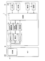
- FIG. 2 is a diagram showing a functional block configuration of the sphygmomanometer according to the present embodiment.
- the sphygmomanometer 1 includes a main body 10, a cuff 20 ⁇ / b> A, and an air tube 80.
- the main body 10 has a box-shaped housing, and a display unit 13 and an operation unit 14 are provided on the upper surface thereof.
- the main body 10 is used by being placed on a placement surface such as a table at the time of measurement.
- the cuff 20A mainly includes an exterior cover 30 and an air bag 34 (see FIGS. 2 and 4), and includes an annular portion into which the upper arm can be inserted from the axial direction.
- the cuff 20A is attached to the upper arm during measurement.
- the air tube 80 connects the main body 10 and the cuff 20 ⁇ / b> A configured separately.
- the main body 10 includes a control unit 11, a memory unit 12, a power supply unit 15, a pressurization pump 17, an exhaust valve 18, a pressure, in addition to the display unit 13 and the operation unit 14 described above.
- the sensor 19 includes a pressure pump drive circuit 17a, an exhaust valve drive circuit 18a, and an oscillation circuit 19a.
- the pressurization pump 17, the exhaust valve 18 and the pressure sensor 19 correspond to the air system component 16 provided in the sphygmomanometer 1.
- the pressurization pump 17 and the exhaust valve 18 are used for inflating and deflating the air bag 34. It corresponds to an expansion / contraction mechanism.
- the air bag 34 is a fluid bag for compressing the upper arm in the mounted state, and has an inflated / deflated space as a lumen therein.
- the air bag 34 is connected to each of the pressurizing pump 17, the exhaust valve 18, and the pressure sensor 19, which are the air system components 16, via the air pipe 80 described above.
- the control unit 11 is configured by, for example, a CPU (Central Processing Unit) and is a part for controlling the entire sphygmomanometer 1.
- the memory unit 12 is composed of, for example, a ROM (Read-Only Memory) or a RAM (Random-Access Memory), and stores a program for causing the control unit 11 to execute a processing procedure for blood pressure measurement, It is a part for storing measurement results and the like.
- the display unit 13 is configured by, for example, an LCD (Liquid Crystal Display) and is a part for displaying measurement results and the like.
- the operation unit 14 is a part for accepting an operation by a subject or the like and inputting an external command to the control unit 11 or the power supply unit 15.
- the power supply unit 15 is a part for supplying power as a power source to the control unit 11.
- the control unit 11 inputs control signals for driving the pressurization pump 17 and the exhaust valve 18 to the pressurization pump drive circuit 17a and the exhaust valve drive circuit 18a, respectively, and the blood pressure value as a measurement result is stored in the memory unit 12 or Or input to the display unit 13.
- the control unit 11 also includes a blood pressure information acquisition unit (not shown) that acquires the blood pressure value of the subject based on the pressure value detected by the pressure sensor 19, and the blood pressure value acquired by the blood pressure information acquisition unit Is input to the memory unit 12 and the display unit 13 described above as measurement results.
- the sphygmomanometer 1 may further include an output unit that outputs a blood pressure value as a measurement result to an external device (for example, a PC (Personal Computer) or a printer).
- the output unit for example, a serial communication line or a writing device for various recording media can be used.
- the pressurization pump drive circuit 17 a controls the operation of the pressurization pump 17 based on the control signal input from the control unit 11.
- the exhaust valve drive circuit 18 a controls the opening / closing operation of the exhaust valve 18 based on the control signal input from the control unit 11.
- the pressurizing pump 17 is for pressurizing the pressure inside the air bladder 34 (hereinafter also referred to as “cuff pressure”) by supplying air to the inner cavity of the air bladder 34, and the operation thereof has been described above. It is controlled by the pressure pump drive circuit 17a.
- the exhaust valve 18 is for maintaining the pressure inside the air bag 34 or opening the lumen of the air bag 34 to the outside to reduce the cuff pressure. The operation of the exhaust valve 18 is described above. Controlled by circuit 18a.
- the pressure sensor 19 inputs an output signal corresponding to the pressure inside the air bladder 34 to the oscillation circuit 19a.
- the oscillation circuit 19 a generates a signal having an oscillation frequency corresponding to the signal input from the pressure sensor 19 and inputs the generated signal to the control unit 11.
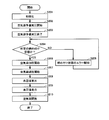
- FIG. 3 is a flowchart showing a process flow of the sphygmomanometer according to the present embodiment. Next, with reference to FIG. 3, the flow of processing of the sphygmomanometer in the present embodiment will be described.
- the program according to this flowchart is stored in advance in the memory unit 12, and the control unit 11 reads out the program from the memory unit 12 and executes it to execute the process.
- the subject When measuring the blood pressure value, the subject wears the cuff 20A on the upper arm in advance and operates the operation unit 14 provided in the main body 10 in this state to turn on the power to the sphygmomanometer 1. Thereby, power as a power source is supplied from the power supply unit 15 to the control unit 11 to drive the control unit 11. As shown in FIG. 3, the controller 11 first initializes the sphygmomanometer 1 after being driven (step S101).
- the control unit 11 waits for a measurement start instruction from the subject, and closes the exhaust valve 18 and drives the pressure pump 17 when the subject gives a measurement start instruction by operating the operation unit 14. And the cuff pressure of the air bladder 34 is increased (step S102).
- the control unit 11 stops the pressurizing pump 17 and then gradually opens the closed exhaust valve 18.
- the air in the air bag 34 is gradually exhausted, and the cuff pressure is gradually reduced (step S103).
- the blood pressure value is measured during the slow depressurization process of the cuff pressure.
- the control unit 11 calculates blood pressure values such as systolic blood pressure values and diastolic blood pressure values by a known procedure (step S104). Specifically, the control unit 11 extracts pulse wave information based on the oscillation frequency obtained from the oscillation circuit 19a in the process of gradually reducing the cuff pressure of the air bladder 34. Then, the control unit 11 calculates a blood pressure value based on the extracted pulse wave information. When the blood pressure value is calculated in step S104, the control unit 11 displays the blood pressure value as a measurement result on the display unit 13 (step S105) and stores the blood pressure value in the memory unit 12.
- control unit 11 opens the air bag 34 to completely exhaust the air in the air bag 34 (step S106), and waits for the subject's power-off command to end the operation.
- the measurement method described above is based on a so-called decompression measurement method that detects a pulse wave when the air bag 34 is decompressed, but a so-called pressurization measurement method that detects a pulse wave when the air bag 34 is pressurized. Of course, it is also possible to adopt.
- FIG. 4 is a cross-sectional view showing a detailed structure of the sphygmomanometer cuff according to the present embodiment.
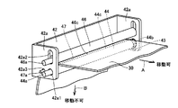
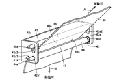
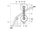
- FIGS. 5A, 5B, 6A, and 6B show the configuration of the fixing mechanism provided in the sphygmomanometer cuff. It is a figure for demonstrating and operation
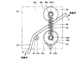
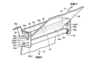
- FIGS. 5A and 5B are a schematic perspective view and a schematic side view showing a state in which the exterior cover is fixed by the fixing mechanism
- FIGS. 6A and 6B show that the fixing by the fixing mechanism of the exterior cover is released. It is the schematic perspective view and model side view which show a state.
- the cuff 20A in the present embodiment mainly includes an air bag 34, an exterior cover 30, an annular ring 36 as a hook member, a puller 38, and a fixing unit 40 as a fixing mechanism. I have.
- the air bag 34 is preferably made of a bag-like member formed using a resin sheet, and has an expansion / contraction space inside.
- the air bag 34 for example, one formed in a bag shape by overlapping two resin sheets and welding the peripheral edges thereof is used.
- the expansion / contraction space of the air bag 34 is connected to the above-described pressurization pump 17 and the exhaust valve 18 via the above-described air pipe 80, and the pressurization pump 17 and the exhaust valve 18 increase or decrease the pressure.
- the material of the resin sheet constituting the air bag 34 any material can be used as long as it is rich in elasticity and does not leak from the expansion / contraction space after welding. From this point of view, suitable materials for the resin sheet include ethylene-vinyl acetate copolymer (EVA), soft vinyl chloride (PVC), polyurethane (PU), natural rubber (NR) and the like.
- EVA ethylene-vinyl acetate copolymer
- PVC soft vinyl chloride
- PU polyurethane
- the outer cover 30 has an inner cover 31 that comes into contact with the surface of the upper arm in the mounted state and an outer cover 32 that is positioned outside the inner cover 31 in the mounted state, and joins the peripheral edges thereof. It is formed as a bag-like belt-like member by sewing (for example, stitching or welding), and has one end 30a and the other end 30b in the longitudinal direction.
- the outer cover 30 contains the air bag 34 described above.
- the inner cover 31 a member sufficiently rich in elasticity is preferably used so that the compression force applied to the upper arm by the expansion of the air bag 34 is not inhibited by the inner cover 31.
- the outer cover 32 a member having less stretchability than the inner cover 31 is used. From such a viewpoint, as the exterior cover 30, a cloth made of synthetic fibers such as polyamide (PA) and polyester capable of adjusting the size of stretchability relatively easily is used.
- PA polyamide
- annular ring 36 is attached to one end 30 a of the exterior cover 30. More specifically, the annular ring 36 is attached to the one end 30 a of the outer cover 30 by inserting a portion near the one end 30 a of the outer cover 30 into the annular ring 36, folding it back and stitching.
- the annular ring 36 is made of, for example, a metal member that hardly causes friction with the exterior cover 30, and has an insertion hole through which a portion near the other end 30 b of the exterior cover 30 can be inserted.
- a handle 38 is attached to the other end 30 b of the exterior cover 30. More specifically, the handle 38 is attached to the other end 30b of the outer cover 30 by inserting a portion near the other end 30b of the outer cover 30 into the puller 38, folding it back and stitching.
- the puller 38 is formed, for example, by injection molding using a resin material as a raw material, and has a grip that can be gripped by hand.
- the fixing unit 40 is provided at a predetermined position on the outer surface of the exterior cover 30.
- the fixing unit 40 includes a housing 41 fixed to the outer cover 30, a support frame 42 disposed inside the housing 41, a roller 44 supported by the support frame 42, a stopper 46, and a driven roller 47,
- a coil spring 45 is mainly provided as a pushing mechanism assembled to the roller 44 and the stopper 46.
- the housing 41 is made of a box-like member extending along the axial direction of the cuff 20A, and has openings 41a and 41b through which portions near the other end 30b of the exterior cover 30 are inserted.
- the support frame 42 is formed by, for example, pressing both ends of a metal flat plate member, and is fixed to the housing 41 while being accommodated in the housing 41.
- the support frame 42 has a pair of side wall portions 42a at both ends in the longitudinal direction (the direction along the axial direction of the cuff 20A).
- the roller 44 is disposed inside the housing 41 so as to extend along the axial direction of the cuff 20A, and is rotatably supported by a pair of side wall portions 42a of the support frame 42. More specifically, each of the pair of side wall portions 42a of the support frame 42 is provided with a perfect circular shaft support hole 42a1, and the shaft 44a of the roller 44 is inserted into the shaft support hole 42a1. Thus, the roller 44 is rotatably supported by the support frame 42.
- Clutch plates 44 b are respectively disposed at predetermined positions near both ends of the roller 44, and each of the clutch plates 44 b is fixed to the shaft 44 a of the roller 44.
- the clutch plate 44b is made of a disk-shaped member, and wedge-shaped teeth are continuously provided along the circumferential direction on the outer peripheral surface thereof.
- Clutch claws 43 are respectively disposed at predetermined positions of the pair of side wall portions 42a of the support frame 42, and each of the clutch claws 43 meshes with the teeth of the clutch plate 44b described above.
- the clutch plate 44b and the clutch pawl 43 function as a so-called one-way clutch. When the clutch pawl 43 is engaged with the clutch plate 44b, the roller 44 can be rotated only in a predetermined direction.
- the surface 44c of the roller 44 is preferably covered with a rubber material.
- a material of the rubber material a material that generates a large frictional force with the exterior cover 30 in a state where the exterior cover 30 is pressed is preferable, and styrene butadiene rubber (SBR), butadiene rubber (BR), Rubbers such as ethylene propylene diene rubber (EPDM), chloroprene rubber (CR), acrylonitrile butadiene rubber (NBR), thermoplastic elastomer (TPE), urethane rubber (U), and silicone rubber (Q) can be used.
- SBR styrene butadiene rubber
- BR butadiene rubber
- Rubbers such as ethylene propylene diene rubber (EPDM), chloroprene rubber (CR), acrylonitrile butadiene rubber (NBR), thermoplastic elastomer (TPE), urethane rubber (U), and silicone rubber (Q) can be used.
- EPDM ethylene
- the stopper 46 is disposed inside the housing 41 so as to extend along the axial direction of the cuff 20A, and is supported by the pair of side wall portions 42a of the support frame 42 so as to be movable and rotatable. More specifically, each of the pair of side wall portions 42a of the support frame 42 is provided with an oval shaft support hole 42a2, and the shaft 46a of the stopper 46 is inserted into the shaft support hole 42a2. Thus, the roller 44 is supported by the support frame 42 so as to be movable and rotatable.
- the stopper 46 it is preferable to use a stopper whose surface 46 c is covered with a rubber material in the same manner as the roller 44 described above, but is not limited to this and is made of a metal or resin member. Also good.
- the shaft support hole 42 a 2 is configured such that the stopper 46 can move between a position close to the roller 44 and a position away from the roller 44 described above, whereby the stopper 46 is close to the roller 44.
- the state (state shown in FIG. 5A and FIG. 5B) arranged at the above position and the state (state shown in FIG. 6A and FIG. 6B) arranged at a position separated from the roller 44 can be taken.
- the driven roller 47 is disposed inside the housing 41 so as to extend along the axial direction of the cuff 20 ⁇ / b> A, and is rotatably supported by a pair of side wall portions 42 a of the support frame 42. More specifically, each of the pair of side wall portions 42a of the support frame 42 is provided with a perfectly circular shaft support hole 42a3, and the shaft 47a of the driven roller 47 is inserted through the shaft support hole 42a3. Accordingly, the driven roller 47 is rotatably supported by the support frame 42.
- the driven roller 47 it is preferable to use a roller whose surface is smooth, and is constituted by, for example, a metal or resin member.
- a coil spring 45 (not shown in FIGS. 5A and 6B) is assembled to the roller 44 and the stopper 46.
- the coil spring 45 is for urging the stopper 46 toward the roller 44, and one end is fixed to the shaft 44 a of the roller 44 and the other end is fixed to the shaft 46 a of the stopper 46.
- the stopper 46 takes a state (ie, the state shown in FIGS. 5A and 5B) that is disposed at a position close to the roller 44 in a state where no external force is applied, among the two states described above. Become.
- the other end 30 b of the exterior cover 30 is inserted through the insertion hole of the annular ring 36 attached to the one end 30 a of the exterior cover 30. While maintaining the annular shape, the portion of the exterior cover 30 near the other end 30b is folded back from the annular ring 36 along the circumferential direction of the annular portion of the exterior cover 30 to form the annular portion. It is superimposed. Therefore, the portion near the other end 30b of the outer cover 30 that is folded back from the annular ring 36 and overlapped with the annular portion corresponds to the overlapping portion.
- the portion of the outer cover 30 that is folded back and closer to the other end 30 b is drawn out of the fixed unit 40 via the fixed unit 40 that is attached to the annular portion of the outer cover 30.
- the above-described puller 38 is attached to the front end of the exterior cover 30 at a portion pulled out from the fixed unit 40.
- the folded portion (that is, the overlapping portion) of the exterior cover 30 passes through openings 41 a and 41 b provided in the housing 41 of the fixed unit 40, and is described above in the housing 41 of the fixed unit 40.
- the roller 44 is in contact with the driven roller 47 and is inserted between the roller 44 and the stopper 46 described above.
- the folded portion of the exterior cover 30 is pressed against the roller 44 by the stopper 46.
- the folded portion of the exterior cover 30 is not fixed to the annular portion. Accordingly, the folded portion of the exterior cover 30 can be moved not only in the direction of arrow A in the figure but also in the direction of arrow B in the figure. Therefore, the cuff 20A can be operated so that the size of the annular portion becomes smaller or larger.
- the folded portion of the outer cover 30 against the urging force of the coil spring 45 is the roller 44.
- the portion near the other end 30b of the exterior cover 30 may be pulled up in the direction of arrow C shown in FIGS. 6A and 6B using the puller 38 so as to move away from the state, and the state shown in FIGS. 5A and 5B is obtained.
- the operation toward the upper side of the puller 38 may be stopped.
- the upper arm is attached according to the following attachment procedure.
- one hand is inserted into the annular portion of the cuff 20A from the axial direction, and the annular portion of the cuff 20A is applied to the upper arm of the inserted arm.
- the handle 38 of the cuff 20A is grasped with the other hand, and the annular portion of the cuff 20A is reduced in diameter by pulling the handle 38 so that the upper arm fits tightly with no gap.
- the annular portion of the cuff 20A does not expand and loosen even if the pulling force of the puller 38 is loosened by the action of the one-way clutch comprising the clutch plate 44b and the clutch pawl 43 described above. This completes the mounting of the cuff 20A on the upper arm.
- the handle 38 is grasped and the portion near the other end 30b of the exterior cover 30 is pulled upward, and between the upper arm and the annular portion of the cuff 20A.
- the removal is completed by creating a gap and extracting the upper arm from the annular portion of the cuff 20A.
- the cuff 20A can be moved with respect to the upper arm by a very simple operation of operating the pull handle 38. It becomes possible to install. At that time, unless a special operation is performed, the diameter of the annular portion of the cuff 20A does not increase and the cuff 20A does not loosen, and the cuff 20A can be attached to the upper arm very easily. Therefore, by adopting the above configuration, it becomes easy to attach the cuff 20A tightly to the upper arm, and it is possible to stably attach the cuff to the upper arm with good reproducibility.
- the cuff 20A and the sphygmomanometer 1 having the same in the present embodiment the cuff is tightened with a simple configuration using the roller 44 and the stopper 46 biased toward the roller 44.
- a fixing mechanism for maintaining the above is configured. Therefore, it is possible to manufacture a cuff that can be stably mounted with good reproducibility without employing a fixing mechanism having a complicated configuration, and the cuff can be manufactured at a very low cost.
- the cuff can be attached by a simple operation, it is possible to easily attach the cuff 20A even to an elderly person or a woman with relatively weak power, which is very easy to handle.
- a sphygmomanometer cuff and a sphygmomanometer equipped with the cuff are provided.
- the annular portion of the cuff 20A can be positioned and attached to an appropriate position of the upper arm relatively easily, and a measurement error due to a displacement of the attachment position can occur.
- the blood pressure decreases, and an accurate blood pressure value can be measured.
- a cuff that can be applied to any subject from a subject having a long upper arm circumference to a subject having a short upper arm circumference, and It can also be a provided blood pressure monitor.
- the sphygmomanometer cuff 20A as in the present embodiment and the sphygmomanometer 1 having the sphygmomanometer cuff 20A can be easily attached to the upper arm as a measurement site and can be stably attached to the upper arm. Can be reproduced, and in addition, a cuff for a sphygmomanometer and a sphygmomanometer including the cuff can be manufactured at low cost.
- FIG. 7A, FIG. 7B, FIG. 8A and FIG. 8B are diagrams showing the configuration and operation of the fixing mechanism of the sphygmomanometer cuff according to the first and second modifications of the present embodiment.
- FIG. 7B and FIG. 8B are schematic side views showing a state in which the fixing of the exterior cover by the fixing mechanism is released.
- the sphygmomanometer cuff and the sphygmomanometer according to the first and second modifications have the same configuration as the sphygmomanometer cuff and the sphygmomanometer in the above-described embodiment, except for the points described below. Therefore, the description will not be repeated here.
- the surfaces 44c and 46c of the roller 44 and the stopper 46 are uneven.
- the unevenness provided on the surfaces 44c and 46c of the roller 44 and the stopper 46 may be a plurality of grooves extending along the axial direction of the cuff, or evenly arranged over the entire surface when the surfaces 44c and 46c are viewed in plan. It may be uneven.
- the surface 44c of the roller 44 and the surface 46c of the stopper 46 are preferably covered with a rubber material as in the case of the cuff for a blood pressure monitor in the present embodiment described above. May be covered.
- the unevenness is for increasing the frictional force between the exterior cover 30 inserted between the roller 44 and the stopper 46 and the surfaces 44c and 46c of the roller 44 and the stopper 46 provided with the unevenness. Irregularities may be provided only on one of the surfaces of the roller 44 and the stopper 46. With this configuration, the exterior cover 30 can be more reliably fixed, so that the cuff 20A can be more securely attached to the upper arm.
- a pressing member 48 as a pressing mechanism is assembled to the roller 44 and the stopper 46.
- the pushing member 48 is made of a shape memory alloy (SMA) that contracts in the energized state to decrease its length in the longitudinal direction and expands in the non-energized state to increase its length in the longitudinal direction.
- SMA shape memory alloy
- the roller 44 and the stopper 46 are assembled with a coil spring 45 that urges the roller 44 and the stopper 46 in the direction of widening the gap between the roller 44 and the stopper 46.
- the pushing member 48 made of a shape memory alloy has one end in the longitudinal direction fixed to the shaft 44 a of the roller 44 and the other end in the longitudinal direction fixed to the shaft 46 a of the stopper 46.
- the pushing member 48 contracts against the biasing force of the coil spring 45 and the stopper 46 approaches the roller 44.
- the outer cover 30 is pressed against the roller 44, and in a non-energized state in which no current is applied to the pressing member 48, the biasing force of the coil spring 45 is also pushed as shown in FIG. 8B.
- the member 48 expands and the stopper 46 is separated from the roller 44, so that the exterior cover 30 is not pressed against the roller 44.
- a member made of a shape memory alloy can be used as a release mechanism (release member 48) for releasing the fixation of the exterior cover 30. In that case, in the energized state in which a current is applied to the release member 48, the release member 48 contracts due to the biasing force of the coil spring 45 as shown in FIG. 8A, and the stopper 46 approaches the roller 44.
- FIG. 9 is a perspective view showing the external structure of the sphygmomanometer cuff according to the second embodiment of the present invention.
- FIGS. 10A and 10B show the configuration and operation of the sphygmomanometer cuff fixing mechanism according to the present embodiment. It is a schematic perspective view for demonstrating.
- the sphygmomanometer cuff in the present embodiment has the same configuration as the sphygmomanometer cuff in the first embodiment of the present invention described above, except for the points described below.
- a pair of rotating members 50 and 51 and a shaft support member 52 are attached to the fixed unit 40.
- the shaft support member 52 is attached so as to bridge a pair of side wall portions 42a of the support frame 42 of the fixed unit 40, and has shaft support portions 52a at both ends thereof.
- the shaft support portion 52a protrudes outward from the pair of side wall portions 42a of the support frame 42, and the rotation members 50 and 51 are fitted into the shaft support portion 52a, respectively.
- each of a pair of rotation members 50 and 51 is attached to support frame 42 so that rotation is possible about axis support part 52a of axis support member 52.
- a predetermined position of each of the pair of rotating members 50 and 51 is loosely fitted to the shaft 46 a of the stopper 46.
- An operation lever portion 50a is provided on one rotation member 50 of the pair of rotation members 50 and 51 so as to continuously extend from the rotation member 50.
- the operation lever portion 50a is , And reaches the outside through an opening provided in the housing 41 of the fixed unit 40.
- the pair of rotating members 50 and 51 and the shaft support member 52 correspond to a position adjusting mechanism that variably adjusts the position of the stopper 46 with respect to the roller 44, and is provided on the rotating member 50.
- the operating lever portion 50a corresponds to a stopper position operating portion for variably adjusting the position of the stopper 46 by manual operation.
- the stopper 46 is positioned close to the roller 44 based on the urging force of the coil spring 45, so that the exterior cover 30. Is pressed against the roller 44, and when the operating lever portion 50a is operated and tilted in the lateral direction, the rotating member rotates against the urging force of the coil spring 45, thereby the stopper 46. Is positioned away from the roller 44, the outer cover 30 is not pressed against the roller 44.
- the outer cover 30 of the folded back portion of the outer cover 30 is operated by operating the operation lever portion 50a.
- the fixing to the annular portion can be easily released, and the cuff can be attached with good operability.
- FIG. 11 is a schematic cross-sectional view for explaining a detailed structure of a sphygmomanometer cuff according to Embodiment 3 of the present invention.
- the sphygmomanometer cuff in the present embodiment has the same configuration as the sphygmomanometer cuff in the first embodiment of the present invention described above, except for the points described below. Since the configuration of the sphygmomanometer provided with the sphygmomanometer cuff is the same as that of the above-described sphygmomanometer according to the first embodiment of the present invention, the description thereof will not be repeated here.
- a curler 35 as a curved elastic plate is included in the exterior cover 30 in addition to the air bag 34.
- the curler 35 is disposed along the outside of the air bag 34 and is made of a flexible member configured to be elastically deformable in the radial direction by being wound in an annular shape.
- the curler 35 may be bonded and fixed to the outer peripheral surface of the air bag 34 via an adhesive member such as a double-sided tape, and is configured to follow the upper arm by maintaining its own annular shape, and the core of the cuff 20C. Become a material.
- the curler 35 is for facilitating wearing of the cuff 20C on the upper arm by the subject himself / herself, and urges the air bag 34 toward the upper arm in the wearing state on the upper arm of the cuff 20C. Is for.
- the curler 35 is formed of a resin member such as polypropylene (PP), for example, so as to exhibit a sufficient elastic force.
- the air bag 34 is reliably pressed against the upper arm in the mounted state to reproduce stable wrapping, as well as pulling to remove the cuff 20C from the upper arm.
- the hand 38 is gripped and the portion near the other end 30b of the exterior cover 30 is pulled downward (see FIG. 6 and the description thereof)
- the restoring force that the curler 35 attempts to expand the diameter causes the above-described embodiment.
- a larger gap than that in the case of the sphygmomanometer cuff configured as in FIG. 1 is generated between the upper arm and the annular portion of the cuff 20C, and the cuff 20C can be easily detached from the upper arm. .
- FIG. 12 is a perspective view showing an external structure of a sphygmomanometer cuff according to Embodiment 4 of the present invention
- FIG. 13 is a schematic cross section for explaining a detailed structure of the sphygmomanometer cuff according to this embodiment.
- the sphygmomanometer cuff in the present embodiment has the same configuration as the sphygmomanometer cuff in the first embodiment of the present invention described above, except for the points described below.
- sphygmomanometer cuff 20 ⁇ / b> D is different from sphygmomanometer cuff 20 ⁇ / b> A according to the above-described first embodiment in that an annular ring is attached to one end 30 a of exterior cover 30. 36 is not provided. Instead, in the sphygmomanometer cuff 20D in the present embodiment, the curler 35 included in the sphygmomanometer cuff 20C in the above-described third embodiment is included in the exterior cover 30.
- the annular shape is maintained by the curler 35, and the portion near the other end 30 b of the exterior cover 30 is superimposed on the annular portion of the exterior cover 30.
- an overlapping portion is formed on the exterior cover 30.
- the overlapping portion of the exterior cover 30 is inserted into the fixed unit 40.
- Embodiment 5 In the first embodiment of the present invention described above, the case where the sphygmomanometer 1 is configured to drive the pressurizing pump 17 and the like to measure the blood pressure value after the cuff 20A is mounted will be described as an example. However, it is also possible to detect whether the winding state of the cuff 20A is in the optimum winding state by slightly pre-pressurizing the air bag 34 prior to the mounting of the cuff 20A. In the following, the case where the sphygmomanometer is configured as described above will be described as Embodiment 5.
- FIG. 14 is a flowchart showing a process flow of the sphygmomanometer according to the fifth embodiment of the present invention.
- the configuration of the sphygmomanometer cuff and the sphygmomanometer provided with the same in the present embodiment is the same as that of the sphygmomanometer in the first embodiment of the present invention described above, and the description thereof will not be repeated here.
- the operation unit 14 provided in the main body 10 is operated to turn on the sphygmomanometer.
- power as a power source is supplied from the power supply unit 15 to the control unit 11 to drive the control unit 11 and initialize the sphygmomanometer (step S201).
- the control unit 11 closes the exhaust valve 18 and drives the pressurization pump 17 to start preliminary pressurization of the air bag 34 (step S202).
- the controller 11 stops driving the pressurizing pump 17 and finishes the preliminary pressurization (step S203).
- the control unit 11 determines whether or not the cuff 20A is in a predetermined tightening state based on a signal input from the oscillation circuit 19a.
- the determination as to whether or not the cuff 20A is in a predetermined tightening state performed in the control unit 11 utilizes the fact that the internal pressure of the air bladder 34 reaches a predetermined pressure in a state where the cuff 20A is tightly attached to the upper arm, The determination is made based on whether or not the signal input from the oscillation circuit 19a described above has reached a predetermined threshold value or more.
- control unit 11 determines that the cuff 20A is not in the predetermined tightening state (NO in step S204)
- the control unit 11 displays an error on the display unit 13 (step S205), and returns to step S204 again to return the cuff 20A to the predetermined state. It is determined whether or not it is in the tightening state.
- the subject performs the cuff 20A installation work. Specifically, referring to the display on the display unit 13, the annular portion of the cuff 20A is reduced in diameter by pulling the pull 38 of the cuff 20A, and tightening is performed until the error display disappears, so that there is no gap in the upper arm. Make the cuff 20A fit exactly.
- Step S204 When the control unit 11 determines that the cuff 20A is in the predetermined tightening state (YES in step S204), the control unit 11 starts driving the pressurizing pump 17 and gradually increases the cuff pressure of the air bladder 34. (Step S206) When the cuff pressure reaches a predetermined level for measuring the blood pressure value, the pressurizing pump 17 is stopped, and then the closed exhaust valve 18 is gradually opened so that the air in the air bag 34 is gradually released. The cuff pressure is gradually reduced (step S207), and the blood pressure value is measured in the slow depressurization process of the cuff pressure.
- control unit 11 calculates blood pressure values such as systolic blood pressure value and diastolic blood pressure value by a known procedure (step S208), and displays the blood pressure value as a measurement result on the display unit 13 (step S209).
- blood pressure value is stored in the memory unit 12, the air bag 34 is opened, the air in the air bag 34 is completely exhausted (step S210), and the operation is terminated after waiting for the subject's power-off command. .
- the blood pressure value measurement is performed only after the cuff 20A is wrapped in a state of being closely fitted to the upper arm, so that a highly accurate blood pressure value measurement is possible. It can be a sphygmomanometer.
- Embodiments 1 to 5 of the present invention described above the case where the surface of the roller is covered with a rubber material or the case where the surface of the roller is provided with unevenness has been described as an example. However, it is not always necessary to be configured in this way, and if the frictional force is sufficient to fix the exterior cover between the surface of the exterior cover and the surface of the roller, the surface of the roller is made of a member other than a rubber material. The surface of the roller may not be provided with unevenness.
- the case where the stopper is supported not only to be movably supported by the support frame but also to be rotatable is described as an example.
- the support frame does not need to be rotatably supported, and may be supported by the support frame so as not to rotate.
- the stopper when the stopper is rotatably supported by the support frame, the stopper may be supported so as to be rotatable only in one direction as in the case of the roller.
- the rotation direction of the stopper is a direction in which the size of the annular portion of the outer cover is reduced in a state where the overlapping portion of the outer cover is sandwiched between the stopper and the roller, as in the case of the roller.
- or 5 of this invention although demonstrated exemplifying the case where the stopper was supported by the support frame so that movement was possible, when it was set as the structure which provides a certain release member,
- the stopper may be fixed to the support frame so as not to move, and the roller may be fixed to the support frame so as to be movable. That is, when the release member is provided, at least one of the roller and the stopper may be configured to be movable.
- the one-way clutch is configured using the clutch plate and the clutch pawl meshing with the clutch plate has been described as an example.
- a one-way clutch having the configuration described above it is also possible to use a one-way clutch having the configuration described above.
- a bearing type can be used as a one-way clutch having another configuration.
- the one-way clutch in the form of a bearing includes an outer ring that is extrapolated with respect to a shaft, and a roller and a spring that are disposed between the outer ring and the shaft.
- the roller meshes with both the outer ring and the shaft by the action of the spring, so that the shaft is driven to rotate in the same direction, and in the direction opposite to the predetermined direction.
- the roller is separated from either the outer ring or the shaft so that the shaft is idled.
- the present invention is not particularly limited to this, so-called wrist-type sphygmomanometer in which a cuff is attached to the wrist when measuring a blood pressure value, a sphygmomanometer cuff provided therein, and an ankle when measuring a blood pressure value
- the present invention can be applied to a so-called ankle-type sphygmomanometer in which a cuff is attached to a sphygmomanometer and a cuff for a sphygmomanometer provided therein.
- the present invention is applied to a sphygmomanometer capable of measuring a blood pressure value such as a systolic blood pressure value and a diastolic blood pressure value, and a sphygmomanometer cuff provided therein.
- blood pressure information other than blood pressure values such as systolic blood pressure value and diastolic blood pressure value (for example, average blood pressure value, pulse wave, pulse, AI value, etc.) can be measured.
Landscapes
- Health & Medical Sciences (AREA)
- Life Sciences & Earth Sciences (AREA)
- Cardiology (AREA)
- Vascular Medicine (AREA)
- Engineering & Computer Science (AREA)
- Medical Informatics (AREA)
- Physics & Mathematics (AREA)
- Ophthalmology & Optometry (AREA)
- Biophysics (AREA)
- Pathology (AREA)
- Dentistry (AREA)
- Biomedical Technology (AREA)
- Heart & Thoracic Surgery (AREA)
- Physiology (AREA)
- Molecular Biology (AREA)
- Surgery (AREA)
- Animal Behavior & Ethology (AREA)
- General Health & Medical Sciences (AREA)
- Public Health (AREA)
- Veterinary Medicine (AREA)
- Measuring Pulse, Heart Rate, Blood Pressure Or Blood Flow (AREA)
Abstract
Description
図1は、本発明の実施の形態1における血圧計の外観構造を示す斜視図であり、図2は、本実施の形態における血圧計の機能ブロックの構成を示す図である。まず、これら図1および図2を参照して、本実施の形態における血圧計の外観構造および機能ブロックの構成について説明する。
図9は、本発明の実施の形態2における血圧計用カフの外観構造を示す斜視図であり、図10Aおよび図10Bは、本実施の形態における血圧計用カフの固定機構の構成および動作を説明するための概略斜視図である。なお、本実施の形態における血圧計用カフは、以下において説明する点を除き、上述した本発明の実施の形態1における血圧計用カフと同様の構成を有しおり、また、本実施の形態における血圧計用カフが具備される血圧計の構成も、上述した本発明の実施の形態1における血圧計と同様であるため、その説明はここでは繰り返さない。
図11は、本発明の実施の形態3における血圧計用カフの詳細な構造を説明するための模式断面図である。なお、本実施の形態における血圧計用カフは、以下において説明する点を除き、上述した本発明の実施の形態1における血圧計用カフと同様の構成を有しおり、また、本実施の形態における血圧計用カフが具備される血圧計の構成も、上述した本発明の実施の形態1における血圧計と同様であるため、その説明はここでは繰り返さない。
図12は、本発明の実施の形態4における血圧計用カフの外観構造を示す斜視図であり、図13は、本実施の形態における血圧計用カフの詳細な構造を説明するための模式断面図である。なお、本実施の形態における血圧計用カフは、以下において説明する点を除き、上述した本発明の実施の形態1における血圧計用カフと同様の構成を有しおり、また、本実施の形態における血圧計用カフが具備される血圧計の構成も、上述した本発明の実施の形態1における血圧計と同様であるため、その説明はここでは繰り返さない。
上述した本発明の実施の形態1においては、カフ20Aの装着後に加圧ポンプ17等を駆動して血圧値を測定する処理を行なうように血圧計1を構成した場合を例示して説明を行なったが、カフ20Aの装着に先立って空気袋34を僅かに予備加圧しておくことにより、カフ20Aの巻き付け状態が最適な巻き付け状態にあるか否かを検知することも可能である。以下においては、そのように血圧計を構成した場合について実施の形態5として説明する。
Claims (8)
- 生体を圧迫するための流体袋(34)と、
生体に巻き付けられる環状の部分および当該環状の部分に重ね合わされた重なり部分を有し、前記流体袋(34)を内包する帯状の外装カバー(30)と、
前記外装カバー(30)の重なり部分を前記外装カバー(30)の環状の部分に固定可能な固定機構(40)とを備え、
前記固定機構(40)は、一方向にのみ回転可能なローラ(44)と、前記ローラ(44)と対峙するストッパ(46)と、前記ストッパ(46)を前記ローラ(44)側に向けて押動可能な押動機構とを含み、
前記外装カバー(30)の重なり部分は、前記ローラ(44)と前記ストッパ(46)との間に挿通され、前記押動機構により前記ストッパ(46)が前記ローラ(44)側に向けて押動されることで前記ローラ(44)の表面に向けて押し付けられ、これにより前記ローラ(44)との間に生じる摩擦力によって前記外装カバー(30)の環状の部分に固定され、
前記ローラ(44)は、前記ストッパ(46)との間で前記外装カバー(30)の重なり部分を挟み込んだ状態において前記外装カバー(30)の環状の部分の大きさが減じる方向にのみ回転可能である、血圧情報測定装置用カフ。 - 前記押動機構は、前記ストッパ(46)を前記ローラ(44)に向けて付勢するバネ(45)にて構成されている、請求の範囲第1項に記載の血圧情報測定装置用カフ。
- 前記押動機構は、通電状態において収縮し、非通電状態において伸張する形状記憶合金からなる部材(48)にて構成されている、請求の範囲第1項に記載の血圧情報測定装置用カフ。
- 前記ローラ(44)と前記ストッパ(46)とを離間させることにより、前記外装カバー(30)の重なり部分が前記外装カバー(30)の環状の部分に固定されることを解除可能にする解除機構をさらに備えた、請求の範囲第1項に記載の血圧情報測定装置用カフ。
- 前記解除機構が、前記ローラ(44)に対する前記ストッパ(46)の位置を相対的に可変に調節する位置調節機構(50,51,52)にて構成されており、
前記位置調節機構(50,51,52)が、手動操作可能なストッパ位置操作部(50a)を有している、請求の範囲第4項に記載の血圧情報測定装置用カフ。 - 前記流体袋(34)の外側に沿って位置するように前記外装カバー(30)に内包され、前記外装カバー(30)の環状の部分の径方向に沿って弾性変形可能な可撓性の湾曲弾性板(35)をさらに備えた、請求の範囲第1項に記載の血圧情報測定装置用カフ。
- 前記外装カバー(30)の長手方向の一端部(30a)に設けられ、前記外装カバー(30)の長手方向の他端部(30b)が挿通されることで前記外装カバー(30)を環状の形態に維持するとともに、前記外装カバー(30)の前記他端部(30b)寄りの部分を前記外装カバー(30)の環状の部分の周方向に沿って折り返し可能にする引っ掛け部材(36)をさらに備え、
前記外装カバー(30)の重なり部分が、前記引っ掛け部材(36)を用いて折り返された部分の前記外装カバー(30)にて構成されている、請求の範囲第1項に記載の血圧情報測定装置用カフ。 - 請求の範囲第1項に記載の血圧情報測定装置用カフ(20A~20D)と、
前記流体袋(34)を膨縮させる膨縮機構(16)と、
血圧情報を取得する血圧情報取得部(11)とを備えた、血圧情報測定装置。
Priority Applications (3)
| Application Number | Priority Date | Filing Date | Title |
|---|---|---|---|
| CN2010800117602A CN102348408B (zh) | 2009-03-12 | 2010-02-17 | 血压信息测定装置用袖带及带该袖带的血压信息测定装置 |
| DE112010001479.5T DE112010001479B4 (de) | 2009-03-12 | 2010-02-17 | Manschette eines Messgeräts für Blutdruckinformationen und Messgerät für Blutdruckinformationen, welches mit selbiger ausgerüstet ist |
| US13/229,930 US9211071B2 (en) | 2009-03-12 | 2011-09-12 | Cuff for blood pressure information measurement device and blood pressure information measurement device equipped with the same |
Applications Claiming Priority (2)
| Application Number | Priority Date | Filing Date | Title |
|---|---|---|---|
| JP2009-059503 | 2009-03-12 | ||
| JP2009059503A JP5257162B2 (ja) | 2009-03-12 | 2009-03-12 | 血圧情報測定装置用カフおよびこれを備えた血圧情報測定装置 |
Related Child Applications (1)
| Application Number | Title | Priority Date | Filing Date |
|---|---|---|---|
| US13/229,930 Continuation US9211071B2 (en) | 2009-03-12 | 2011-09-12 | Cuff for blood pressure information measurement device and blood pressure information measurement device equipped with the same |
Publications (1)
| Publication Number | Publication Date |
|---|---|
| WO2010103897A1 true WO2010103897A1 (ja) | 2010-09-16 |
Family
ID=42728190
Family Applications (1)
| Application Number | Title | Priority Date | Filing Date |
|---|---|---|---|
| PCT/JP2010/052347 Ceased WO2010103897A1 (ja) | 2009-03-12 | 2010-02-17 | 血圧情報測定装置用カフおよびこれを備えた血圧情報測定装置 |
Country Status (7)
| Country | Link |
|---|---|
| US (1) | US9211071B2 (ja) |
| JP (1) | JP5257162B2 (ja) |
| CN (1) | CN102348408B (ja) |
| AR (1) | AR078028A1 (ja) |
| DE (1) | DE112010001479B4 (ja) |
| TW (1) | TWI494080B (ja) |
| WO (1) | WO2010103897A1 (ja) |
Cited By (3)
| Publication number | Priority date | Publication date | Assignee | Title |
|---|---|---|---|---|
| JP2010207520A (ja) * | 2009-03-12 | 2010-09-24 | Omron Healthcare Co Ltd | 血圧情報測定装置用カフおよびこれを備えた血圧情報測定装置 |
| WO2016006595A1 (ja) * | 2014-07-10 | 2016-01-14 | オムロンヘルスケア株式会社 | 血圧測定用カフおよびその装着方法 |
| CN108030483A (zh) * | 2017-12-06 | 2018-05-15 | 深圳市星河泉新材料有限公司五金配件分厂 | 一种加压结构、血压检测模块以及血压智能检测设备 |
Families Citing this family (12)
| Publication number | Priority date | Publication date | Assignee | Title |
|---|---|---|---|---|
| JP5556244B2 (ja) * | 2010-03-03 | 2014-07-23 | オムロンヘルスケア株式会社 | 血圧情報測定装置用カフおよびこれを備えた血圧情報測定装置 |
| JP5633447B2 (ja) * | 2011-03-24 | 2014-12-03 | オムロンヘルスケア株式会社 | 血圧情報測定装置用カフの製造方法 |
| EP2832779B1 (en) * | 2013-08-01 | 2018-06-06 | 3M Innovative Properties Company | Pressure Sensitive Adhesive Foam |
| US10213248B2 (en) | 2013-08-21 | 2019-02-26 | Biosense Webster (Israel) Ltd. | Adaptive electrode for bi-polar ablation |
| CN104434073B (zh) * | 2014-12-24 | 2017-01-11 | 深圳瑞光康泰科技有限公司 | 自动血压测量装置 |
| US10750957B2 (en) | 2017-04-28 | 2020-08-25 | Edwards Lifesciences Corporation | Clamp mechanism to assist in attaching a finger cuff |
| CN107280686B (zh) * | 2017-07-25 | 2021-09-24 | 潘军强 | 一种无创可穿戴式的血糖仪 |
| US11918539B2 (en) | 2020-06-10 | 2024-03-05 | Welch Allyn, Inc. | Wearable health management system |
| US12343305B2 (en) | 2020-08-12 | 2025-07-01 | Welch Allyn, Inc. | Health management system |
| CN114469030B (zh) * | 2021-03-08 | 2024-11-12 | 四川卫生康复职业学院 | 一种一次性腕带及腕式血压计 |
| TWI855923B (zh) * | 2023-11-16 | 2024-09-11 | 百略醫學科技股份有限公司 | 手臂式血壓計 |
| CN118303859B (zh) * | 2024-04-08 | 2024-09-13 | 明识科技(广州)有限公司 | 一种具有血压检测功能的佩戴式检测设备 |
Citations (5)
| Publication number | Priority date | Publication date | Assignee | Title |
|---|---|---|---|---|
| JPS61206546U (ja) * | 1985-06-17 | 1986-12-26 | ||
| JPS6234553U (ja) * | 1985-08-16 | 1987-02-28 | ||
| JPH0237604U (ja) * | 1988-09-06 | 1990-03-13 | ||
| JP2000237150A (ja) * | 1999-02-19 | 2000-09-05 | Omron Corp | 血圧計用カフ |
| JP2002209858A (ja) * | 2001-01-23 | 2002-07-30 | Omron Corp | 血圧計の腕帯 |
Family Cites Families (16)
| Publication number | Priority date | Publication date | Assignee | Title |
|---|---|---|---|---|
| US837013A (en) * | 1906-04-04 | 1906-11-27 | Henry H Wachter | Trace-carrier. |
| DE2906517C2 (de) * | 1979-02-20 | 1981-03-26 | Geroh GmbH Mechanische Systeme, 91344 Waischenfeld | Vorrichtung zum Führen und Festklemmen eines Seiles oder Kabels, insbesonders bei freistehenden Masten wie Masten von beweglichen Antennenanlagen oder auf Zelten mit Abspannseilen |
| JPS59232531A (ja) | 1983-06-15 | 1984-12-27 | 松下電工株式会社 | 血圧計 |
| JPS6092039U (ja) | 1983-11-30 | 1985-06-24 | 株式会社東芝 | 冷凍サイクル |
| JPS6356003A (ja) | 1986-08-26 | 1988-03-10 | Matsushita Electric Works Ltd | マイクロ波アンテナ装置 |
| JPH0443206Y2 (ja) | 1986-09-30 | 1992-10-13 | ||
| JPS63117095U (ja) | 1987-01-22 | 1988-07-28 | ||
| JPS63125915U (ja) | 1987-02-09 | 1988-08-17 | ||
| JPH0237604A (ja) * | 1988-07-26 | 1990-02-07 | Ono Gijutsu Kenkyusho:Kk | 薄型ライトボックス |
| DE10224042A1 (de) | 2002-05-31 | 2003-12-18 | Braun Gmbh | Blutdruckmeßgerät |
| JP3675796B2 (ja) * | 2002-08-05 | 2005-07-27 | コーリンメディカルテクノロジー株式会社 | 血圧測定装置 |
| JP4595449B2 (ja) | 2004-09-02 | 2010-12-08 | オムロンヘルスケア株式会社 | 血圧計用カフ |
| JP4708931B2 (ja) | 2005-09-13 | 2011-06-22 | 日本精密測器株式会社 | 空気袋付きバンドの締結機構、それを含むエアマッサージ装置および血圧計 |
| JP4665757B2 (ja) * | 2005-12-27 | 2011-04-06 | オムロンヘルスケア株式会社 | 血圧計用カフおよびこれを備えた血圧計 |
| JP4237195B2 (ja) | 2006-03-31 | 2009-03-11 | シチズンホールディングス株式会社 | 血圧計用腕帯のコアの製造方法及び血圧計用腕帯 |
| JP5257162B2 (ja) * | 2009-03-12 | 2013-08-07 | オムロンヘルスケア株式会社 | 血圧情報測定装置用カフおよびこれを備えた血圧情報測定装置 |
-
2009
- 2009-03-12 JP JP2009059503A patent/JP5257162B2/ja not_active Expired - Fee Related
-
2010
- 2010-02-17 DE DE112010001479.5T patent/DE112010001479B4/de active Active
- 2010-02-17 CN CN2010800117602A patent/CN102348408B/zh not_active Expired - Fee Related
- 2010-02-17 WO PCT/JP2010/052347 patent/WO2010103897A1/ja not_active Ceased
- 2010-03-11 TW TW099107029A patent/TWI494080B/zh not_active IP Right Cessation
- 2010-03-12 AR ARP100100794A patent/AR078028A1/es active IP Right Grant
-
2011
- 2011-09-12 US US13/229,930 patent/US9211071B2/en active Active
Patent Citations (5)
| Publication number | Priority date | Publication date | Assignee | Title |
|---|---|---|---|---|
| JPS61206546U (ja) * | 1985-06-17 | 1986-12-26 | ||
| JPS6234553U (ja) * | 1985-08-16 | 1987-02-28 | ||
| JPH0237604U (ja) * | 1988-09-06 | 1990-03-13 | ||
| JP2000237150A (ja) * | 1999-02-19 | 2000-09-05 | Omron Corp | 血圧計用カフ |
| JP2002209858A (ja) * | 2001-01-23 | 2002-07-30 | Omron Corp | 血圧計の腕帯 |
Cited By (6)
| Publication number | Priority date | Publication date | Assignee | Title |
|---|---|---|---|---|
| JP2010207520A (ja) * | 2009-03-12 | 2010-09-24 | Omron Healthcare Co Ltd | 血圧情報測定装置用カフおよびこれを備えた血圧情報測定装置 |
| WO2016006595A1 (ja) * | 2014-07-10 | 2016-01-14 | オムロンヘルスケア株式会社 | 血圧測定用カフおよびその装着方法 |
| JP2016016232A (ja) * | 2014-07-10 | 2016-02-01 | オムロンヘルスケア株式会社 | 血圧測定用カフおよびその装着方法 |
| US10405759B2 (en) | 2014-07-10 | 2019-09-10 | Omron Healthcare Co., Ltd. | Blood pressure measurement cuff and attachment method thereof |
| CN108030483A (zh) * | 2017-12-06 | 2018-05-15 | 深圳市星河泉新材料有限公司五金配件分厂 | 一种加压结构、血压检测模块以及血压智能检测设备 |
| CN108030483B (zh) * | 2017-12-06 | 2023-12-29 | 深圳市星河泉新材料有限公司 | 一种加压结构、血压检测模块以及血压智能检测设备 |
Also Published As
| Publication number | Publication date |
|---|---|
| AR078028A1 (es) | 2011-10-12 |
| CN102348408A (zh) | 2012-02-08 |
| US20120004560A1 (en) | 2012-01-05 |
| TWI494080B (zh) | 2015-08-01 |
| TW201043192A (en) | 2010-12-16 |
| US9211071B2 (en) | 2015-12-15 |
| JP2010207520A (ja) | 2010-09-24 |
| JP5257162B2 (ja) | 2013-08-07 |
| CN102348408B (zh) | 2013-10-30 |
| DE112010001479B4 (de) | 2025-02-06 |
| DE112010001479T5 (de) | 2012-09-06 |
Similar Documents
| Publication | Publication Date | Title |
|---|---|---|
| JP5257162B2 (ja) | 血圧情報測定装置用カフおよびこれを備えた血圧情報測定装置 | |
| JP5076996B2 (ja) | 血圧情報測定装置 | |
| JP5151801B2 (ja) | 血圧情報測定装置用カフおよびこれを備えた血圧情報測定装置 | |
| JP5169552B2 (ja) | 血圧情報測定装置用カフおよびこれを備えた血圧情報測定装置 | |
| JP5556244B2 (ja) | 血圧情報測定装置用カフおよびこれを備えた血圧情報測定装置 | |
| CN101522097B (zh) | 血压计用袖带和血压计 | |
| JP5145930B2 (ja) | 血圧計用カフおよび血圧計 | |
| KR102017067B1 (ko) | 손목 혈압계 | |
| WO2011122259A1 (ja) | 手首式血圧計 | |
| JP2012200508A (ja) | 血圧情報測定装置用カフおよびこれを備えた血圧情報測定装置 | |
| WO2007119482A1 (ja) | 血圧計用カフ | |
| JP5251447B2 (ja) | 血圧情報測定装置用カフおよびこれを備えた血圧情報測定装置 | |
| WO2011105197A1 (ja) | 血圧情報測定装置用カフおよびこれを備えた血圧情報測定装置 | |
| CN101977548A (zh) | 血压计用袖带及具有该袖带的血压计 | |
| WO2014102871A1 (ja) | 血圧計 | |
| JP5141679B2 (ja) | 血圧情報測定装置用カフおよびこれを備えた血圧情報測定装置 | |
| JP5460233B2 (ja) | 電子血圧計 | |
| JP2010069196A (ja) | 血圧計用カフおよび血圧計 | |
| WO2014102873A1 (ja) | 血圧計および血圧計の腕帯部の製造方法 |
Legal Events
| Date | Code | Title | Description |
|---|---|---|---|
| WWE | Wipo information: entry into national phase |
Ref document number: 201080011760.2 Country of ref document: CN |
|
| 121 | Ep: the epo has been informed by wipo that ep was designated in this application |
Ref document number: 10750652 Country of ref document: EP Kind code of ref document: A1 |
|
| WWE | Wipo information: entry into national phase |
Ref document number: 112010001479 Country of ref document: DE Ref document number: 1120100014795 Country of ref document: DE |
|
| 122 | Ep: pct application non-entry in european phase |
Ref document number: 10750652 Country of ref document: EP Kind code of ref document: A1 |
|
| WWG | Wipo information: grant in national office |
Ref document number: 112010001479 Country of ref document: DE |