WO2010103749A1 - メッキ用治具 - Google Patents
メッキ用治具 Download PDFInfo
- Publication number
- WO2010103749A1 WO2010103749A1 PCT/JP2010/001436 JP2010001436W WO2010103749A1 WO 2010103749 A1 WO2010103749 A1 WO 2010103749A1 JP 2010001436 W JP2010001436 W JP 2010001436W WO 2010103749 A1 WO2010103749 A1 WO 2010103749A1
- Authority
- WO
- WIPO (PCT)
- Prior art keywords
- substrate
- plating
- elastic member
- support frame
- frame
- Prior art date
- Legal status (The legal status is an assumption and is not a legal conclusion. Google has not performed a legal analysis and makes no representation as to the accuracy of the status listed.)
- Ceased
Links
Images

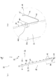


Classifications
-
- C—CHEMISTRY; METALLURGY
- C25—ELECTROLYTIC OR ELECTROPHORETIC PROCESSES; APPARATUS THEREFOR
- C25D—PROCESSES FOR THE ELECTROLYTIC OR ELECTROPHORETIC PRODUCTION OF COATINGS; ELECTROFORMING; APPARATUS THEREFOR
- C25D17/00—Constructional parts, or assemblies thereof, of cells for electrolytic coating
- C25D17/06—Suspending or supporting devices for articles to be coated
- C25D17/08—Supporting racks, i.e. not for suspending
-
- H—ELECTRICITY
- H05—ELECTRIC TECHNIQUES NOT OTHERWISE PROVIDED FOR
- H05K—PRINTED CIRCUITS; CASINGS OR CONSTRUCTIONAL DETAILS OF ELECTRIC APPARATUS; MANUFACTURE OF ASSEMBLAGES OF ELECTRICAL COMPONENTS
- H05K3/00—Apparatus or processes for manufacturing printed circuits
- H05K3/22—Secondary treatment of printed circuits
- H05K3/24—Reinforcing of the conductive pattern
- H05K3/241—Reinforcing of the conductive pattern characterised by the electroplating method; means therefor, e.g. baths or apparatus
Definitions
- the present invention relates to a plating jig.
- Patent Documents 1 and 2 describe inventions of a substrate holding jig for holding a substrate on a rectangular frame composed of a pair of opposed horizontal and vertical rails for plating. Has been.
- the jig described in the above document has a problem that the plating solution is reattached to the substrate pulled up from the plating solution due to liquid dripping from a horizontal rail provided above the upper side.
- the thickness of the formed plating becomes non-uniform, which requires a post-processing step for polishing the substrate surface after plating.
- the present invention has been made in view of the above problems, and provides a plating jig capable of preventing dripping of a substrate pulled up from a plating solution.
- the plating jig of the present invention is a plating jig for detachably holding a rectangular substrate and immersing the substrate in a plating solution, A pair of vertical members holding both sides in the width direction of the substrate; An upper horizontal member that is provided above the upper side of the substrate to be held and connects the vertical members to each other; and The lower side edge of the upper lateral member is convex upward.
- the convex shape of the lower edge is monotonous toward the longitudinal member with the intermediate position in the width direction of the substrate as a vertex. It may be inclined downward.
- the plating jig of the present invention holds a flexible printed wiring board as the substrate, A support frame including the pair of vertical members; An opening / closing frame provided so as to be openable / closable with respect to the support frame and sandwiching the both sides of the substrate together with the vertical member; At least one of the support frame and the opening / closing frame may be provided with a plurality of elastic members protruding to urge the both sides of the substrate toward the outside in the vertical direction.
- the second elastic member for biasing to The first elastic member is provided above the boundary height, with the lower side than the intermediate height of the support frame or the opening / closing frame as the boundary height, and the second elastic member below the boundary height. May be provided.
- the opening / closing frame is rotatable with respect to the support frame about a rotation axis extending in the width direction below the substrate.
- the first elastic member may have a larger protruding height from the support frame or the opening / closing frame than the second elastic member.
- the first and second elastic members stand up from the support frame or the opening / closing frame toward the outside in the vertical direction. It may be a bent leaf spring.
- the elastic member is formed in a protruding shape with a pressing point for pressing the substrate to be held in the vicinity of the tip of the one piece. May be.
- the elastic member includes a flat plate-like extending portion on the tip side further than the pressing point, When the substrate is sandwiched between the support frame and the opening / closing frame, the extending portion may press the substrate before the pressing point.
- the vertical direction is defined in the present invention, this is defined for convenience in order to briefly explain the relative relationship of the components of the present invention. It does not limit the direction of use.
- the various components of the present invention do not have to be individually independent, that a plurality of components are formed as one member, and one component is formed of a plurality of members. It may be that a certain component is a part of another component, a part of a certain component overlaps a part of another component, and the like.
- the plating solution adhered to the surface of the upper horizontal member by forming the lower edge of the upper horizontal member provided above the upper side of the substrate convex upward. Will be transmitted along the lower edge toward the vertical members on both sides. As a result, the plating solution does not drop from the upper lateral member toward the substrate, and no dripping occurs on the substrate.
- (A) is a front view which shows an example of the jig
- (b) is the right view.
- (A) is a right view of the jig for plating which shows the state which opened the opening-and-closing frame with respect to the support frame, (b) is the elements on larger scale. It is a perspective view explaining the use condition of the jig for plating which hold
- (A) is a top view of an elastic member, and the same figure (b) is the elevation. It is a schematic diagram which shows a mode that a board
- FIG.1 (a) is a front view which shows an example of the jig
- the same figure (b) is the right view.
- 2A is a right side view of the plating jig 10 showing a state in which the opening / closing frame 30 is opened with respect to the support frame 20, and
- FIG. 2B is surrounded by a circle B in FIG. It is the elements on larger scale which show an area
- FIG. 3 is a perspective view for explaining a usage state of the plating jig 10 of the present embodiment holding the substrate 50.
- the vertical direction and the horizontal direction are defined as shown.
- the front-rear direction is defined as shown.
- the up-down direction and the left-right direction are in-plane directions of the substrate 50, and the front-rear direction is a direction perpendicular to the substrate 50.
- the plating jig 10 is a jig for holding the rectangular substrate 50 in a detachable manner and immersing the substrate 50 in the plating solution 60.
- the plating jig 10 is provided above the pair of vertical members 21 and 22 that hold both sides 51 and 52 in the width direction of the substrate 50 and the upper side 53 of the substrate 50 that is held, and the vertical members 21 and 22.
- an upper lateral member 23 that connects the two.
- the lower edge 231 of the upper horizontal member 23 has a convex shape.
- the plating jig 10 is a jig for immersing the substrate 50 in a plating solution 60 stored in a plating tank 62 opened upward and plating the surface of the substrate 50. .
- the plating jig 10 can be driven forward / backward in the front-rear direction and up / down in the vertical direction by the conveying device 70.
- a plurality of plating tanks 62 are installed in the front-rear direction, and the same or different types of plating solutions 60 and cleaning solutions are stored in each other.
- the plating treatment applied to the substrate 50 is not particularly limited, and various chemical treatments and pretreatments can be exemplified in addition to metal plating by electric (electrolytic) plating or electroless plating.
- the metal plating include copper plating, nickel plating, chrome plating, zinc plating, tin plating, silver plating, gold plating, and alloy plating such as solder.
- the conveyance device 70 includes a carrier bar 72 that is horizontally installed and holds the plating jig 10 in a suspended manner, an elevating unit 76 that holds both ends 73 of the carrier bar 72, and a slide rail 79 that drives the elevating unit 76 to move up and down. And a frame 78 provided in the vertical direction.
- the frame 78 drives the lifting unit 76 up and down by the slide rail 79, and the frame 78 itself advances and retreats in the front-rear direction.
- the elevating part 76 protrudes inward in the left-right direction from the frame 78.
- a holder 74 provided in the elevating unit 76 holds the end 73 of the carrier bar 72.
- the plating jig 10 holding the substrate 50 is driven by the transfer device 70 so as to be able to advance and retreat and to move up and down. Then, the plating jig 10 set on the upper part of the predetermined plating tank 62 is lowered, the substrate 50 is immersed in the plating solution 60 together with the plating jig 10, and is pulled up again to raise the main surface 55 of the substrate 50. Is plated.
- the plating jig 10 of the present embodiment prevents dripping of the plating solution 60 with respect to the main surface 55 of the substrate 50 during the pulling up.
- the plating jig 10 includes an upper horizontal member 23 that is provided above the upper side 53 of the substrate 50 to be held and connects the vertical members 21 and 22 together.
- the lower edge 231 has comprised the convex shape upwards.
- the affinity with the lower edge 231 acts on the plating solution 60 adhering to the upper lateral member 23 together with gravity. For this reason, the plating solution 60 flows down in the left-right direction along the lower edge 231 due to the inclination direction component of the lower edge 231 of gravity. Since the plating solution 60 does not leave the lower edge 231 due to the affinity with the lower edge 231, the plating solution 60 adhering to the upper lateral member 23 does not fall from the upper lateral member 23 and becomes dripping. There is no.
- the plating solution 60 adhering to the upper lateral member 23 is removed from the longitudinal member 21 or the longitudinal member at the tip of the downward inclined direction. It can flow down toward the member 22. However, in this case, since the flow-down distance along the upper horizontal member 23 becomes longer, the plating solution 60 is easily separated from the lower edge 231 and dropped toward the substrate 50 in the middle.
- the convex shape of the lower edge 231 is monotonously inclined downward toward the vertical members 21 and 22 with the intermediate position in the width direction of the substrate 50 as the vertex 232. ing.
- the height of the apex 232 is not particularly limited.
- the apex 232 may be about 5 to 10 mm or higher. That is, the tangent (tan) of the inclination angle of the lower edge 231 is preferably 0.02 to 0.04 or more.
- the substrate 50 that is held by the plating jig 10 of the present embodiment shown in FIG. 1 and used for the plating process is not particularly limited.
- a flexible printed circuit board FPC: Flexible Printed Circuits
- a rigid board having a thickness of about 600 ⁇ m or less can be given.
- the substrate 50 has a rectangular shape, and at least opposite side sides (vertical sides) 51 and 52 are held by the support frame 20 of the plating jig 10 of this embodiment.
- the substrate 50 is held by the plating jig 10 in an upright state and immersed in the plating solution 60.
- the side sides 51 and 52 are held by the support frame 20 means that the side sides 51 and 52 or the vicinity thereof are held by the support frame 20, and the left and right side edges are the support frame 20. It is not necessary to be in contact with. That is, the side edges 51 and 52 may slightly protrude outward from the left and right sides of the support frame 20.
- substrate 50 is a rectangle means that a pair of side 51,52 which opposes is substantially parallel.
- the side edges 51 and 52 are not necessarily strictly parallel, and may be non-parallel within the width of the vertical members 21 and 22 of the support frame 20. Further, the upper side 53 and the lower side 54 of the substrate 50 may be parallel to each other or non-parallel. In addition, each side of the substrate 50 may be linear or include an uneven portion as long as the retention by the plating jig 10 is not impaired.
- the plating jig 10 detachably holds a flexible printed wiring board as a board 50.
- the manner in which the substrate 50 is held by the plating jig 10 is not particularly limited as long as the upper horizontal member 23 is provided above the upper side 53 of the substrate 50 so as to be spaced apart.
- the substrate 50 is sandwiched between the support frame 20 including a pair of vertical members 21 and 22 extending in the vertical direction and the open / close frame 30. An embodiment is illustrated.
- the open / close frame 30 of the present embodiment is a frame that is provided so as to be openable and closable with respect to the support frame 20 and sandwiches both sides 51 and 52 of the substrate 50 together with the vertical members 21 and 22.
- the present invention is not limited to this.
- the substrate 50 may be sucked and held by the vertical members 21 and 22, or the side edges 51 and 52 of the substrate 50 may be pressed and held by an elastic clip.
- the shape of the vertical members 21 and 22 that hold both sides 51 and 52 in the width direction of the substrate 50 is not particularly limited, and may be a plate shape or a rod shape.
- the vertical members 21 and 22 of this embodiment are formed in a long plate shape that extends in the vertical direction in parallel with the substrate 50.
- the upper ends of the vertical members 21 and 22 are bent to form a hook portion 27.
- the hook part 27 is a part for suspending the plating jig 10 on the carrier bar 72 (see FIG. 3) of the transport device 70.
- the plating jig 10 suspended on the carrier bar 72 is fixed by the push screw 28.
- the upper portions of the vertical members 21 and 22 are curved backward by an amount corresponding to the plate thickness to form an upward extending portion 29.
- the substrate 50 can be held immediately below the carrier bar 72 by curving the upper extending portion 29 backward.
- the base plate 26 (26a, 26b) is affixed on the front surface of the vertical members 21, 22.
- the base plate 26 has a long rectangular plate shape and is narrower than the vertical members 21 and 22.
- the support frame 20 of the present embodiment includes a lower horizontal member 24 that connects the lower ends of the vertical members 21 and 22.
- a lower horizontal member 24 that connects the lower ends of the vertical members 21 and 22.
- whether or not the lower side 54 of the substrate 50 is held by the lower horizontal member 24 is arbitrary.
- the lower side 54 of the substrate 50 contacts the front surface of the lower horizontal member 24, but is not sandwiched between the opening / closing frame 30 and the lower horizontal member 24. Thereby, the liquid drop of the plating solution 60 flowing down from the substrate 50 pulled up from the plating tank 62 is not hindered by the opening / closing frame 30, and the plating solution 60 does not stay near the lower side 54.
- the plating jig 10 of the present embodiment does not hold the upper side 53 of the substrate 50 and does not have a lateral member that contacts the upper side 53. This is for avoiding liquid dripping from the lateral member that holds or abuts the upper side 53 of the substrate 50. That is, the open / close frame 30 of the present embodiment holds only both sides of the substrate 50 by the vertical bars 33a and 33b extending in the vertical direction.
- the support frame 20 of the present embodiment has a substantially rectangular shape with a pair of opposing vertical members 21 and 22 and an upper horizontal member 23 and a lower horizontal member 24 that connect them in the left-right direction.
- the open / close frame 30 that is rotatable with respect to the support frame 20 and sandwiches the substrate 50 together with the support frame 20 includes a pair of vertical bars 33 (33a, 33b) facing the vertical members 21, 22, and the vertical bars 33a, 33a, The rotating shaft 32 and the horizontal rail 37 which connect 33b mutually are provided.
- the vertical cross 33 has a U-shaped cross section cut perpendicularly to the extending direction (vertical direction). Specifically, the vertical rail 33 is erected on both sides of the long pressing plate 34 facing the pedestal plate 26 of the support frame 20 and the width direction of the pressing plate 34 (the left-right direction in FIG. 1A). And a pair of side plates 35 (35a, 35b).
- the rotating shaft 32 provided in the vicinity of the lower end of the vertical beam 33 and the horizontal beam 37 provided in the vicinity of the upper end each have a cylindrical shape.
- the cross-sectional shape of the horizontal rail 37 is not particularly limited. The rotating shaft 32 and the horizontal rail 37 penetrate the side plate 35 of the vertical rail 33 in the width direction.
- a bearing 36 is provided that protrudes forward (to the left in FIG. 1B) of the plating jig 10 and that rotatably constrains both ends of the rotary shaft 32.
- the horizontal rail 37 is provided through a total of four side plates 35 (35a, 35b) of the pair of vertical rails 33. Both ends of the horizontal beam 37 protrude outward from the vertical beam 33.
- hooks 25 are rotatably provided on both outer sides in the width direction.
- tool 10 for plating of this embodiment is not specifically limited, Typically, metal materials, such as stainless steel (SUS), can be used.
- the surface of the pedestal plate 26 and the vertical rail 33 which may be immersed in the plating solution 60 and come into contact with the substrate 50 may be non-conductive.
- the pedestal plate 26 and the vertical rail 33 may be made of a non-metallic non-conductive material, or an insulating layer made of a non-conductive material such as sol may be formed on the surface of the metal material. .
- At least one of the support frame 20 and the opening / closing frame 30 protrudes from a plurality of elastic members 40 that urge the side sides 51 and 52 of the substrate 50 sandwiched between the plating jigs 10 outward in the vertical direction.
- the elastic member 40 protrudes from the support frame 20 toward the opening / closing frame 30 or from the opening / closing frame 30 toward the support frame 20.
- the elastic member 40 may be provided only on the support frame 20, provided only on the opening / closing frame 30, or may be provided on both.
- a leaf spring protruding from the opening / closing frame 30 toward the support frame 20 is exemplified as the elastic member 40.
- the present invention is not limited to this, and a rod-like or spherical member may be used as the elastic member 40.
- the elastic member 40 is an urging member for keeping the flexible substrate 50 flat by applying a predetermined tension. By stretching the substrate 50 to the support frame 20 or the open / close frame 30 by the elastic member 40, it is possible to prevent the substrate 50 to be plated from being loosened or wrinkled. In addition, according to the plating jig 10 of this embodiment in which the substrate 50 is pressed and supported by the elastic member 40, it is possible to hold a plurality of types of substrates 50 having different plate thicknesses for general purposes.
- the material of the elastic member 40 is not particularly limited, but a metal material such as stainless steel (SUS) is preferably used from the viewpoint of elasticity and durability.
- the elastic member 40 when the elastic member 40 is made of a conductive material such as a metal material, the elastic member 40 can be used as an electrode in electrolytic plating. That is, an area to be plated, which is optionally patterned, is formed on the surface of the substrate 50 with a metal material. On the other hand, an electrode pad conducted to the region to be plated is provided along the side edges 51 and 52 of the substrate 50, and the elastic member 40 is pressed against the electrode pad. Then, when the elastic member 40 is energized through the opening / closing frame 30, the substrate 50 is subjected to electrolytic plating in the region to be plated.
- SUS stainless steel
- the plating jig 10 includes a first elastic member 41 that urges the side edges 51 and 52 of the substrate 50 upward with respect to the pair of vertical bars 33a and 33b, respectively, and both side edges 51 and 52 of the board 50. And the second elastic member 42 for urging each of them downward as an elastic member 40. As shown in FIG. 2A, the plating jig 10 has a boundary height BH that is lower than the intermediate height of the support frame 20 or the opening / closing frame 30, and is higher than the boundary height BH. One elastic member 41 is provided, and a second elastic member 42 is provided below the boundary height BH.
- a plurality of first elastic members 41 are provided above the boundary height BH below the intermediate height of the opening / closing frame 30 with respect to the rotation shaft 32 as a reference.
- a plurality of second elastic members 42 are provided below the boundary height BH.
- the first elastic member 41 and the second elastic member 42 are arranged side by side on the pressing plate 34 of the vertical bar 33.
- the first elastic member 41 being above the boundary height BH means that at least a part of the first elastic member 41 is above the boundary height BH.
- the second elastic member 42 being below the boundary height BH means that at least a part of the second elastic member 42 is below the boundary height BH.
- the first elastic member 41 (elastic member 40) is attached to the pressing plate 34 of the vertical beam 33 by screws 491 and nuts 492. As shown in FIG.
- FIG. 4A is a plan view of the elastic member 40
- FIG. 4B is an elevation view thereof.
- the first and second elastic members 41, 42 are bending leaf springs in which one piece (standing piece 43) rises outward from the support frame 20 or the opening / closing frame 30 in the vertical direction.
- the elastic member 40 (the first elastic member 41 and the second elastic member 42) of the present embodiment is formed by bending a plate material such as metal at an acute angle at the bending portion 48.
- the bent piece (standing piece 43) stands obliquely from the pressing plate 34, and the other piece (base piece 44) is provided with a screw hole 49 through which a screw 491 is inserted.
- a pressing point 45 for pressing the substrate 50 to be held is formed in a protruding shape in the vicinity of the tip of the upright piece 43. As a result, the elastic force of the bending leaf spring is urged toward the substrate 50 in a concentrated manner.
- FIG. 5 is a schematic diagram showing a state in which the substrate 50 is pressed by the first elastic member 41.
- the first elastic member 41 of the present embodiment includes a flat plate-like extending portion 47 on the distal end side of the standing piece 43 further than the pushing point 45. As shown in the figure, when the substrate 50 is sandwiched between the support frame 20 and the opening / closing frame 30, the extending portion 47 contacts and presses the substrate 50 before the pressing point 45.
- the pushing point 45 is displaced in the direction of a substantially arcuate arrow centered on the curved portion 48. Such a displacement direction is forward and upward with respect to the opening / closing frame 30. Accordingly, the concentrated load applied to the substrate 50 by the push point 45 includes an upward component in the in-plane direction of the substrate 50. Therefore, the first elastic member 41 biases the side 51 (or side 52) of the substrate 50 upward. It should be noted that the urging force exerted on the substrate 50 by the extending portion 47 of the upright piece 43 also includes an upward component for the same reason as described above (a) to (b).
- the flat extending portion 47 comes into contact with the substrate 50 before the pressing point 45, so that the concentrated load due to the pressing point 45 is applied to the substrate 50.
- a predetermined urging force acts on the substrate 50 from the extending portion 47 to apply tension to the substrate 50.
- the pushing point 45 comes into contact with the substrate 50 in a state where the slack and wrinkles of the substrate 50 in the initial state set on the support frame 20 are stretched in advance by the stretching portion 47. Therefore, compared with the case where the substrate 50 is urged from the beginning at the pushing point 45, the rapid stretching of the substrate 50 is suppressed and the substrate 50 is prevented from being damaged.
- the upright piece 43 extends upward from the curved portion 48, so that the urging direction by the extending portion 47 and the pushing point 45 is upward along with the right side of the surface of the substrate 50. Will be included.
- the second elastic member 42 includes a downward component on the contrary to the first elastic member 41 because the protruding direction of the standing piece 43 is downward. An urging force can be applied to the substrate 50. Thereby, according to the jig 10 for plating of this embodiment, this can be hold
- the boundary height BH that divides the load point that urges the substrate 50 upward and the load point that urges the substrate downward is lower than the intermediate height of the support frame 20 or the opening / closing frame 30 in this embodiment. It is in. Accordingly, when various substrates 50 having different heights are sandwiched between the plating jigs 10, an upward and downward urging force can be applied to each substrate 50. That is, for example, when the boundary height BH is the intermediate height of the opening / closing frame 30, when holding the substrate 50 having a height less than half of the opening / closing frame 30, an upward biasing force is applied to the substrate 50. It is difficult to sufficiently stretch the substrate 50.
- the boundary height BH is lower than the intermediate height of the opening / closing frame 30, specifically, about a quarter of the opening / closing frame 30 as in the plating jig 10 of the present embodiment.
- the substrate 50 having a height less than half of the opening / closing frame 30 can be suitably held by the plating jig 10.
- the opening / closing frame 30 of the present embodiment is rotatable with respect to the support frame 20 around a rotation shaft 32 extending in the width direction below the substrate 50. That is, the opening / closing frame 30 opens upward with respect to the support frame 20.
- the first elastic member 41 has a larger protruding height from the support frame 20 or the opening / closing frame 30 than the second elastic member 42.
- the height at which the first elastic member 41 provided on the upper side of the opening / closing frame 30 protrudes from the vertical rail 33 is the height of the second elastic member 42. It is larger than the height protruding from the vertical beam 33.
- the opening and closing frame 30 is closed with respect to the support frame 20, and the timing at which the first elastic member 41 starts pressing against the substrate 50 and the timing at which the second elastic member 42 starts pressing are set. It can be almost simultaneous. For this reason, the upward urging force and the downward urging force with respect to the substrate 50 act on the substrate 50 almost simultaneously, so that the substrate 50 can be given tension without causing a positional shift with respect to the support frame 20.
- the protrusion height of each of the plurality of first elastic members 41 or the second elastic members 42 that are further arranged on the upper part of the opening / closing frame 30 is set. It is smaller than the protruding height of what is arranged in the lower part.
- first elastic member 41 may be a length L 2 of the standing base end portion 46 shown in FIG. 4 (b) may be made different from each other.
- the length L 1 of the base piece 44 and the length L 3 of the extending portion 47 may be common to all the first elastic members 41 and the second elastic members 42 or may be different from each other.
- one or both of the first elastic member 41 and the second elastic member 42 may be detachable from the plating jig 10. Then, depending on the characteristics such as the height dimension, thickness, and material of the substrate 50 held by the plating jig 10, the protruding direction of the upright base end 46 in the first elastic member 41 or the second elastic member 42 is determined. It may be reversed upside down or replaced with another elastic member having a different size.
- the lower the first resilient member 41 and second resilient length of the standing base end portion 46 of the member 42 L 2 is shorter, or the spring constant of the leaf spring Alternatively, it may be replaced with another elastic member.
- the tension applied to the substrate 50 in the vertical direction in the plane is loosened, and the substrate 50 is prevented from being damaged.
- the height dimension of the substrate 50 is equal to or less than a predetermined value, one or two or more mounting members positioned on the upper side among a plurality (four in FIG. 2A) of the second elastic members 42 are mounted. The direction may be reversed upside down. As a result, even when the substrate 50 having a low height is held by the plating jig 10, the tension applied to the surface of the substrate 50 is balanced vertically.
- FIG. 6 is a perspective view schematically showing a state in which the substrate 50 is held by the plating jig 10 of the present embodiment.
- the substrate 50 is set on the plating jig 10 in a state where the suction jig 80 is combined from behind.
- the suction jig 80 includes a flat suction surface 82 in which a number of suction holes 83 capable of negative pressure suction are formed, and a step portion 84 provided in a step-down manner on both left and right sides of the suction surface 82. .
- the height of the step between the suction hole 83 and the step portion 84 is equal to the total thickness of the vertical member 21 or 22 of the plating jig 10 and the base plate 26.
- the width dimension of the suction surface 82 in the left-right direction is slightly smaller than the distance between the vertical member 21 and the vertical member 22.
- the vertical dimension of the suction surface 82 is smaller than the minimum distance between the lower horizontal member 24 and the upper horizontal member 23.
- the suction surface 82 of the suction jig 80 can be fitted into the inside of the support frame 20 from behind, and the suction surface 82 and the pedestal can be fitted with the suction jig 80 fitted to the support frame 20.
- the plate 26 is flush with the plate. In this state, by sucking the inside of the suction hole 83 with a blower (not shown), the substrate 50 applied across the pair of base plates 26 can be sucked and held on the suction surface 82. Therefore, even when the operator removes his / her hand from the substrate 50 when closing the opening / closing frame 30, the state where the substrate 50 is stretched on the support frame 20 can be maintained.
- the plating jig 10 is kept standing.
- the substrate 50 can be set on the support frame 20.
- substrate 50 can be set with the jig
- suction holes 83 may be formed in the stepped portion 84 of the suction jig 80, and through holes communicating with the other suction holes 83 may be provided for the vertical members 21, 22 and the base plate 26. Good. Thereby, both sides 51 and 52 of the substrate 50 and the vicinity thereof can be sucked and held when the opening / closing frame 30 is closed.
- the substrate 50 is sandwiched between the opening / closing frame 30 and the support frame 20, and the blower is stopped after the horizontal rail 37 of the opening / closing frame 30 is locked by the hook 25, so that the plating jig 10 and the substrate 50 are attached to the suction jig. It leaves
Landscapes
- Chemical & Material Sciences (AREA)
- Engineering & Computer Science (AREA)
- Chemical Kinetics & Catalysis (AREA)
- Electrochemistry (AREA)
- Materials Engineering (AREA)
- Metallurgy (AREA)
- Organic Chemistry (AREA)
- Electroplating Methods And Accessories (AREA)
- Manufacturing Of Printed Wiring (AREA)
Abstract
メッキ用治具(10)は、矩形の基板(50)を着脱可能に保持して基板(50)をメッキ液に浸漬する治具である。メッキ用治具(10)は、基板(50)の幅方向の両側辺(51),(52)を保持する一対の縦部材(21),(22)と、保持される基板(50)の上辺(53)よりも上部に設けられて縦部材(21),(22)同士を連結する上部横部材(23)と、を備えている。上部横部材(23)の下側縁(231)は上に凸形状をなしている。これにより、メッキ液から引き上げられた基板(50)に対する液垂れが防止される。
Description
本発明は、メッキ用治具に関する。
プリント配線基板などの基板を治具によって起立状態で保持してメッキ液に浸漬する技術が知られている。この種の技術に関し、下記特許文献1および2には、各対向する一対の横桟と縦桟とからなる矩形枠体に基板を保持してメッキ処理に供する基板保持用治具の発明が記載されている。
しかしながら、上記文献に記載の治具では、メッキ液から引き上げられた基板に対して、その上辺よりも上部に設けられた横桟からの液垂れによりメッキ液が再付着するという問題がある。基板の表面にメッキ液が再付着すると、形成されるメッキの膜厚が不均一になるため、メッキ後の基板表面を研磨する後処理工程を要することとなる。
本発明は上記課題に鑑みてなされたものであり、メッキ液から引き上げられた基板に対する液垂れを防止することのできるメッキ用治具を提供するものである。
本発明のメッキ用治具は、矩形の基板を着脱可能に保持して前記基板をメッキ液に浸漬するためのメッキ用治具であって、
前記基板の幅方向の両側辺を保持する一対の縦部材と、
保持される前記基板の上辺よりも上部に設けられて前記縦部材同士を連結する上部横部材と、を備えるとともに、
前記上部横部材の下側縁が上に凸形状をなすことを特徴とする。
前記基板の幅方向の両側辺を保持する一対の縦部材と、
保持される前記基板の上辺よりも上部に設けられて前記縦部材同士を連結する上部横部材と、を備えるとともに、
前記上部横部材の下側縁が上に凸形状をなすことを特徴とする。
また本発明のメッキ用治具においては、より具体的な実施の態様として、前記下側縁の前記凸形状が、前記基板の幅方向の中間位置を頂点として、前記縦部材に向かってそれぞれ単調に下り傾斜していてもよい。
また本発明のメッキ用治具は、より具体的な実施の態様として、可撓性のプリント配線基板を前記基板として保持するものであって、
前記一対の縦部材を含む支持枠と、
前記支持枠に対して開閉自在に設けられて、前記縦部材とともに前記基板の前記両側辺を挟持する開閉枠と、をさらに備えるとともに、
前記支持枠または前記開閉枠の少なくとも一方には、前記基板の前記両側辺をそれぞれ上下方向の外側に向かって付勢する複数の弾性部材が突出して設けられていてもよい。
前記一対の縦部材を含む支持枠と、
前記支持枠に対して開閉自在に設けられて、前記縦部材とともに前記基板の前記両側辺を挟持する開閉枠と、をさらに備えるとともに、
前記支持枠または前記開閉枠の少なくとも一方には、前記基板の前記両側辺をそれぞれ上下方向の外側に向かって付勢する複数の弾性部材が突出して設けられていてもよい。
また本発明のメッキ用治具においては、より具体的な実施の態様として、前記基板の前記両側辺をそれぞれ上向きに付勢する第一の前記弾性部材と、前記基板の前記両側辺をそれぞれ下向きに付勢する第二の前記弾性部材と、を備えるとともに、
前記支持枠または前記開閉枠の中間高さよりも下側を境界高さとして、前記境界高さよりも上方に前記第一の弾性部材が設けられ、前記境界高さよりも下方に前記第二の弾性部材が設けられていてもよい。
前記支持枠または前記開閉枠の中間高さよりも下側を境界高さとして、前記境界高さよりも上方に前記第一の弾性部材が設けられ、前記境界高さよりも下方に前記第二の弾性部材が設けられていてもよい。
また本発明のメッキ用治具においては、より具体的な実施の態様として、前記開閉枠が、前記基板の下方に幅方向に延在する回転軸を中心に前記支持枠に対して回動可能であるとともに、
前記第一の弾性部材が、前記第二の弾性部材よりも、前記支持枠または前記開閉枠からの突出高さが大きくてもよい。
前記第一の弾性部材が、前記第二の弾性部材よりも、前記支持枠または前記開閉枠からの突出高さが大きくてもよい。
また本発明のメッキ用治具においては、より具体的な実施の態様として、前記第一および第二の弾性部材が、前記支持枠または前記開閉枠より上下方向の前記外側に向かって一片が立ち上がる曲げ板バネであってもよい。
また本発明のメッキ用治具においては、より具体的な実施の態様として、前記弾性部材は、前記一片の先端部近傍に、保持される前記基板を押圧するための押し点が突起状に形成されていてもよい。
また本発明のメッキ用治具においては、より具体的な実施の態様として、前記弾性部材は、前記押し点よりもさらに先端側に平板状の延伸部を備え、
前記支持枠と前記開閉枠とで前記基板を挟持する際に、前記押し点よりも先に前記延伸部が前記基板を押圧してもよい。
前記支持枠と前記開閉枠とで前記基板を挟持する際に、前記押し点よりも先に前記延伸部が前記基板を押圧してもよい。
なお、本発明では上下方向を規定しているが、これは本発明の構成要素の相対関係を簡単に説明するために便宜的に規定したものであり、本発明を実施する場合の製造時や使用時の方向を限定するものではない。
また、本発明の各種の構成要素は、個々に独立した存在である必要はなく、複数の構成要素が一個の部材として形成されていること、一つの構成要素が複数の部材で形成されていること、ある構成要素が他の構成要素の一部であること、ある構成要素の一部と他の構成要素の一部とが重複していること、等でもよい。
また、本発明の各種の構成要素は、個々に独立した存在である必要はなく、複数の構成要素が一個の部材として形成されていること、一つの構成要素が複数の部材で形成されていること、ある構成要素が他の構成要素の一部であること、ある構成要素の一部と他の構成要素の一部とが重複していること、等でもよい。
本発明のメッキ用治具によれば、基板の上辺よりも上部に設けられた上部横部材の下側縁が上に凸形状をなしていることにより、上部横部材の表面に付着したメッキ液は、両側の縦部材に向かって下側縁を伝うこととなる。これにより、上部横部材から基板に向かってメッキ液が落下することがなく、基板には液垂れが生じない。
上述した目的、およびその他の目的、特徴および利点は、以下に述べる好適な実施の形態、およびそれに付随する以下の図面によってさらに明らかになる。
以下、本発明の実施形態を図面に基づいて説明する。尚、すべての図面において、同様な構成要素には同様の符号を付し、適宜説明を省略する。
図1(a)は、本発明の実施形態にかかるメッキ用治具10の一例を示す正面図であり、同図(b)はその右側面図である。
図2(a)は開閉枠30を支持枠20に対して開放した状態を示すメッキ用治具10の右側面図であり、図2(b)は同図(a)において円Bで囲った領域を示す部分拡大図である。
図3は、基板50を保持した本実施形態のメッキ用治具10の使用状態を説明する斜視図である。
図2(a)は開閉枠30を支持枠20に対して開放した状態を示すメッキ用治具10の右側面図であり、図2(b)は同図(a)において円Bで囲った領域を示す部分拡大図である。
図3は、基板50を保持した本実施形態のメッキ用治具10の使用状態を説明する斜視図である。
図1、2では、説明のため、上下方向および左右方向を図示のように規定する。また、図3では、上下方向および左右方向に加えて前後方向を図示のように規定する。上下方向および左右方向は基板50の面内方向であり、前後方向は基板50の面直方向である。
はじめに、本実施形態のメッキ用治具10の概要について説明する。
メッキ用治具10は、矩形の基板50を着脱可能に保持して基板50をメッキ液60に浸漬する治具である。
メッキ用治具10は、基板50の幅方向の両側辺51,52を保持する一対の縦部材21,22と、保持される基板50の上辺53よりも上部に設けられて縦部材21,22同士を連結する上部横部材23と、を備えている。
そして、本実施形態のメッキ用治具10は、上部横部材23の下側縁231が上に凸形状をなしている。
メッキ用治具10は、矩形の基板50を着脱可能に保持して基板50をメッキ液60に浸漬する治具である。
メッキ用治具10は、基板50の幅方向の両側辺51,52を保持する一対の縦部材21,22と、保持される基板50の上辺53よりも上部に設けられて縦部材21,22同士を連結する上部横部材23と、を備えている。
そして、本実施形態のメッキ用治具10は、上部横部材23の下側縁231が上に凸形状をなしている。
次に、本実施形態のメッキ用治具10について詳細に説明する。
図3に示すように、メッキ用治具10は、上方開口したメッキ槽62に蓄えられたメッキ液60に基板50を浸漬して、基板50の表面にメッキ処理を施すための治具である。
メッキ用治具10は、搬送装置70によって前後方向の進退駆動および上下方向の昇降駆動が自在になされる。
メッキ槽62は前後方向に複数台が設置され、互いに同種または異種のメッキ液60や洗浄液が貯留されている。
図3に示すように、メッキ用治具10は、上方開口したメッキ槽62に蓄えられたメッキ液60に基板50を浸漬して、基板50の表面にメッキ処理を施すための治具である。
メッキ用治具10は、搬送装置70によって前後方向の進退駆動および上下方向の昇降駆動が自在になされる。
メッキ槽62は前後方向に複数台が設置され、互いに同種または異種のメッキ液60や洗浄液が貯留されている。
基板50に施されるメッキ処理は特に限定されるものではなく、電気(電解)メッキまたは無電解メッキによる金属メッキのほか、各種の化成処理、前処理を例示することができる。金属メッキとしては、銅メッキやニッケルメッキ、クロムメッキ、亜鉛メッキ、錫メッキ、銀メッキ、金メッキ、ハンダ等の合金メッキを一例として挙げることができる。
搬送装置70は、水平に架設されてメッキ用治具10を垂下保持するキャリアバー72と、キャリアバー72の両端部73を保持する昇降部76と、昇降部76を昇降駆動するスライドレール79が上下方向に設けられたフレーム78と、を供えている。
フレーム78は、スライドレール79によって昇降部76を昇降駆動するとともに、フレーム78自身が前後方向に進退する。
昇降部76はフレーム78より左右方向内側に突出している。昇降部76に設けられたホルダ74は、キャリアバー72の端部73を保持する。
これにより、基板50を保持した状態のメッキ用治具10は、搬送装置70によって進退および昇降自在に駆動される。そして、所定のメッキ槽62の上部にセットされたメッキ用治具10を降下させてメッキ用治具10とともに基板50をメッキ液60に浸漬し、これを再び引き上げることで基板50の主面55に対するメッキ処理が行われる。
フレーム78は、スライドレール79によって昇降部76を昇降駆動するとともに、フレーム78自身が前後方向に進退する。
昇降部76はフレーム78より左右方向内側に突出している。昇降部76に設けられたホルダ74は、キャリアバー72の端部73を保持する。
これにより、基板50を保持した状態のメッキ用治具10は、搬送装置70によって進退および昇降自在に駆動される。そして、所定のメッキ槽62の上部にセットされたメッキ用治具10を降下させてメッキ用治具10とともに基板50をメッキ液60に浸漬し、これを再び引き上げることで基板50の主面55に対するメッキ処理が行われる。
本実施形態のメッキ用治具10は、かかる引き上げの際に、基板50の主面55に対するメッキ液60の液垂れを防止するものである。
メッキ用治具10は、図1および3に示すように、保持される基板50の上辺53よりも上部に設けられて縦部材21,22同士を連結する上部横部材23を供えている。そして、本実施形態の上部横部材23は、その下側縁231が上に凸形状をなしている。
これにより、メッキ槽62から基板50が引き上げられる際に、基板50の上部に位置する上部横部材23に付着していたメッキ液60が下側縁231を左右方向に伝わって流れ、縦部材21,22より下方に流下する。ここで、上部横部材23に付着しているメッキ液60には、重力とともに下側縁231との親和力が作用する。このため、重力のうちの下側縁231の傾斜方向成分によって、メッキ液60は下側縁231に沿って左右方向に流下する。そして、下側縁231との親和力によりメッキ液60は下側縁231から離脱しないため、上部横部材23に付着していたメッキ液60は上部横部材23から落下せず、液垂れとなることがない。
メッキ用治具10は、図1および3に示すように、保持される基板50の上辺53よりも上部に設けられて縦部材21,22同士を連結する上部横部材23を供えている。そして、本実施形態の上部横部材23は、その下側縁231が上に凸形状をなしている。
これにより、メッキ槽62から基板50が引き上げられる際に、基板50の上部に位置する上部横部材23に付着していたメッキ液60が下側縁231を左右方向に伝わって流れ、縦部材21,22より下方に流下する。ここで、上部横部材23に付着しているメッキ液60には、重力とともに下側縁231との親和力が作用する。このため、重力のうちの下側縁231の傾斜方向成分によって、メッキ液60は下側縁231に沿って左右方向に流下する。そして、下側縁231との親和力によりメッキ液60は下側縁231から離脱しないため、上部横部材23に付着していたメッキ液60は上部横部材23から落下せず、液垂れとなることがない。
ここで、下側縁231が左右いずれかの方向に単調に下り傾斜している場合も、上部横部材23に付着していたメッキ液60を、下り傾斜方向の先にある縦部材21または縦部材22に向かって流下させることができる。しかし、この場合、上部横部材23に沿った流下距離が長くなるため、メッキ液60は途中で下側縁231から離脱して基板50に向かって落下しやすくなる。
これに対し、本実施形態の上部横部材23は、下側縁231の凸形状が、基板50の幅方向の中間位置を頂点232として、縦部材21,22に向かってそれぞれ単調に下り傾斜している。
これにより、頂点232から、縦部材21または縦部材22までの距離が等しくなるため、基板50に対する液垂れの防止効果を左右方向に対して均等に得ることができる。
頂点232の高さは特に限定されないが、一例として、上部横部材23の幅寸法を500mmとした場合に、頂点232を5~10mm程度以上の高さとすればよい。すなわち、下側縁231の傾斜角度の正接(tan)を0.02~0.04、またはそれ以上にするとよい。
これにより、頂点232から、縦部材21または縦部材22までの距離が等しくなるため、基板50に対する液垂れの防止効果を左右方向に対して均等に得ることができる。
頂点232の高さは特に限定されないが、一例として、上部横部材23の幅寸法を500mmとした場合に、頂点232を5~10mm程度以上の高さとすればよい。すなわち、下側縁231の傾斜角度の正接(tan)を0.02~0.04、またはそれ以上にするとよい。
図1に示す本実施形態のメッキ用治具10に保持されてメッキ処理に供される基板50は、特に限定されない。一例として、厚さ30~150μmの可撓性のプリント配線基板(FPC:Flexible Printed Circuits)や、厚さ600μm程度以下のリジッド基板を挙げることができる。
基板50は矩形をなし、本実施形態のメッキ用治具10の支持枠20により、少なくとも対向する両側辺(縦辺)51,52が保持される。
基板50は、起立した状態でメッキ用治具10に保持されてメッキ液60に浸漬される。
ここで、側辺51,52が支持枠20に保持されるとは、当該側辺51,52またはその近傍が支持枠20に保持されていることを意味し、左右の両側縁が支持枠20に接触していることを要するものではない。すなわち、側辺51,52が支持枠20よりも左右の外方に僅かに突出していてもよい。
なお、基板50が矩形であるとは、対向する一対の側辺51,52が略平行であることを意味する。側辺51,52が厳密に平行であることは必ずしも要さず、支持枠20の縦部材21,22の幅内で非平行であってもよい。また、基板50の上辺53および下辺54に関しても、互いに平行であっても、非平行であってもよい。
また、基板50の各辺は、メッキ用治具10による保持性を損なわない限りにおいて、直線状であっても凹凸部を含んでもよい。
基板50は、起立した状態でメッキ用治具10に保持されてメッキ液60に浸漬される。
ここで、側辺51,52が支持枠20に保持されるとは、当該側辺51,52またはその近傍が支持枠20に保持されていることを意味し、左右の両側縁が支持枠20に接触していることを要するものではない。すなわち、側辺51,52が支持枠20よりも左右の外方に僅かに突出していてもよい。
なお、基板50が矩形であるとは、対向する一対の側辺51,52が略平行であることを意味する。側辺51,52が厳密に平行であることは必ずしも要さず、支持枠20の縦部材21,22の幅内で非平行であってもよい。また、基板50の上辺53および下辺54に関しても、互いに平行であっても、非平行であってもよい。
また、基板50の各辺は、メッキ用治具10による保持性を損なわない限りにおいて、直線状であっても凹凸部を含んでもよい。
メッキ用治具10は、可撓性のプリント配線基板を基板50として着脱可能に保持する。メッキ用治具10による基板50の保持態様は、上部横部材23が基板50の上辺53よりも上方に離間して設けられている限り、特に限定されない。
本実施形態のメッキ用治具10では、図1、2に示すように、上下方向に延在する一対の縦部材21,22を含む支持枠20と、開閉枠30とで基板50を挟持する態様を例示する。本実施形態の開閉枠30は、支持枠20に対して開閉自在に設けられて、縦部材21,22とともに基板50の両側辺51,52を挟持する枠体である。
ただし、本発明はこれに限られず、例えば、縦部材21,22によって基板50を吸引保持しても、弾性のあるクリップによって基板50の側辺51,52を押圧保持してもよい。
本実施形態のメッキ用治具10では、図1、2に示すように、上下方向に延在する一対の縦部材21,22を含む支持枠20と、開閉枠30とで基板50を挟持する態様を例示する。本実施形態の開閉枠30は、支持枠20に対して開閉自在に設けられて、縦部材21,22とともに基板50の両側辺51,52を挟持する枠体である。
ただし、本発明はこれに限られず、例えば、縦部材21,22によって基板50を吸引保持しても、弾性のあるクリップによって基板50の側辺51,52を押圧保持してもよい。
基板50の幅方向の両側辺51,52を保持する縦部材21,22の形状は特に限定されず、板状や棒状でもよい。本実施形態の縦部材21,22は、基板50と平行して上下方向に伸びる長尺の板状に形成されている。
縦部材21,22の上端部は折り曲げられてフック部27が形成されている。フック部27は、搬送装置70のキャリアバー72(図3を参照)にメッキ用治具10を懸架するための部位である。
キャリアバー72に懸架されたメッキ用治具10は、押しネジ28によって固定される。
縦部材21,22の上部は、その板厚分程度だけ後方に湾曲して、上方延在部29が形成されている。上方延在部29を後方に湾曲させることにより、キャリアバー72の直下にて基板50を保持することができる。
縦部材21,22の上端部は折り曲げられてフック部27が形成されている。フック部27は、搬送装置70のキャリアバー72(図3を参照)にメッキ用治具10を懸架するための部位である。
キャリアバー72に懸架されたメッキ用治具10は、押しネジ28によって固定される。
縦部材21,22の上部は、その板厚分程度だけ後方に湾曲して、上方延在部29が形成されている。上方延在部29を後方に湾曲させることにより、キャリアバー72の直下にて基板50を保持することができる。
縦部材21,22の前面には、台座プレート26(26a,26b)が貼り付けられている。台座プレート26は長尺の矩形板状をなし、縦部材21,22よりも細幅である。
本実施形態の支持枠20は、縦部材21,22の下端同士を連結する下部横部材24を供えている。本発明において、下部横部材24によって基板50の下辺54を保持するか否かは任意である。
本実施形態では、基板50の下辺54は下部横部材24の前面に当接するが、開閉枠30と下部横部材24とで挟持されてはいない。これにより、メッキ槽62から引き上げられる基板50から流下するメッキ液60の液ぎれを開閉枠30で阻害せず、メッキ液60が下辺54の近傍で滞留することがない。
本実施形態では、基板50の下辺54は下部横部材24の前面に当接するが、開閉枠30と下部横部材24とで挟持されてはいない。これにより、メッキ槽62から引き上げられる基板50から流下するメッキ液60の液ぎれを開閉枠30で阻害せず、メッキ液60が下辺54の近傍で滞留することがない。
一方、本実施形態のメッキ用治具10は、基板50の上辺53を保持せず、また上辺53と当接する横部材を有していない。これは、基板50の上辺53を保持またはこれに当接する横部材からの液垂れを回避するためである。すなわち、本実施形態の開閉枠30は、上下方向に延在する縦桟33a,33bによって、基板50の両側辺のみを保持している。
本実施形態の支持枠20は、対向する一対の縦部材21,22と、これらを左右方向に連結する上部横部材23および下部横部材24とで、略矩形状をなしている。
支持枠20に対して回動可能であって支持枠20とともに基板50を挟持する開閉枠30は、縦部材21,22に対向する一対の縦桟33(33a,33b)と、縦桟33a,33bを相互に連結する回転軸32および横桟37とを備える
支持枠20に対して回動可能であって支持枠20とともに基板50を挟持する開閉枠30は、縦部材21,22に対向する一対の縦桟33(33a,33b)と、縦桟33a,33bを相互に連結する回転軸32および横桟37とを備える
縦桟33は、延在方向(上下方向)対して垂直に切った横断面がコ字(U字)状をなす。具体的には、縦桟33は、支持枠20の台座プレート26に対向する長尺の押圧板34と、押圧板34の幅方向(図1(a)における左右方向)の両側に立設された一対の側板35(35a,35b)とからなる。
本実施形態の場合、縦桟33の下端近傍に設けられる回転軸32と、上端近傍に設けられる横桟37は、それぞれ円柱状をなしている。ただし、横桟37の横断面形状は特に限定されない。
回転軸32および横桟37は、縦桟33の側板35を幅方向に貫通している。
縦部材21の下端近傍には、メッキ用治具10の前方(図1(b)における左方)に突出して、回転軸32の両端部を回動可能に拘束する軸受36が設けられている。
一方、横桟37は、一対の縦桟33が有する合計4枚の側板35(35a,35b)を貫いて設けられている。
横桟37の両端は縦桟33の両外側に突出している。縦部材21,22には、幅方向の両外側にフック25(25a,25b)が回動可能に設けられている。そして、回転軸32を中心に開閉枠30を回動させてこれを支持枠20に押し当てた状態で、フック25を横桟37に掛合することで、開閉枠30と支持枠20は互いにロックされる。
本実施形態の場合、縦桟33の下端近傍に設けられる回転軸32と、上端近傍に設けられる横桟37は、それぞれ円柱状をなしている。ただし、横桟37の横断面形状は特に限定されない。
回転軸32および横桟37は、縦桟33の側板35を幅方向に貫通している。
縦部材21の下端近傍には、メッキ用治具10の前方(図1(b)における左方)に突出して、回転軸32の両端部を回動可能に拘束する軸受36が設けられている。
一方、横桟37は、一対の縦桟33が有する合計4枚の側板35(35a,35b)を貫いて設けられている。
横桟37の両端は縦桟33の両外側に突出している。縦部材21,22には、幅方向の両外側にフック25(25a,25b)が回動可能に設けられている。そして、回転軸32を中心に開閉枠30を回動させてこれを支持枠20に押し当てた状態で、フック25を横桟37に掛合することで、開閉枠30と支持枠20は互いにロックされる。
本実施形態のメッキ用治具10を構成する材料は特に限定されるものではなく、典型的にはステンレス鋼(SUS)などの金属材料を用いることができる。
また、メッキ液60に浸漬されて基板50と接触する可能性のある台座プレート26や縦桟33は、表面を非導電性としてもよい。この場合、台座プレート26や縦桟33を非金属の非導電性材料で作製してもよく、または金属材料の表面にゾルなどの非導電性材料からなる絶縁層を塗膜形成してもよい。
また、メッキ液60に浸漬されて基板50と接触する可能性のある台座プレート26や縦桟33は、表面を非導電性としてもよい。この場合、台座プレート26や縦桟33を非金属の非導電性材料で作製してもよく、または金属材料の表面にゾルなどの非導電性材料からなる絶縁層を塗膜形成してもよい。
支持枠20または開閉枠30の少なくとも一方には、メッキ用治具10に挟持される基板50の両側辺51,52をそれぞれ上下方向の外側に向かって付勢する複数の弾性部材40が突出して設けられている。
弾性部材40は、支持枠20から開閉枠30に向かって、または開閉枠30から支持枠20に向かって突出している。なお、弾性部材40は、支持枠20のみに設けられても、開閉枠30のみに設けられても、両者にそれぞれ設けられてもよい。
本実施形態では、開閉枠30から支持枠20に向かって突出する板バネを弾性部材40として例示する。ただし、本発明はこれに限られず、弾性部材40として棒状や球状の部材を用いてもよい。
弾性部材40は、支持枠20から開閉枠30に向かって、または開閉枠30から支持枠20に向かって突出している。なお、弾性部材40は、支持枠20のみに設けられても、開閉枠30のみに設けられても、両者にそれぞれ設けられてもよい。
本実施形態では、開閉枠30から支持枠20に向かって突出する板バネを弾性部材40として例示する。ただし、本発明はこれに限られず、弾性部材40として棒状や球状の部材を用いてもよい。
弾性部材40は、可撓性の基板50に所定のテンションをかけて平坦に保つための付勢部材である。
弾性部材40によって基板50を支持枠20または開閉枠30に張設することで、メッキ処理される基板50に弛みや皺が生じることを防止することができる。
また、弾性部材40によって基板50を押圧支持する本実施形態のメッキ用治具10によれば、互いに板厚の異なる複数種類の基板50を汎用的に保持することが可能となる。
弾性部材40によって基板50を支持枠20または開閉枠30に張設することで、メッキ処理される基板50に弛みや皺が生じることを防止することができる。
また、弾性部材40によって基板50を押圧支持する本実施形態のメッキ用治具10によれば、互いに板厚の異なる複数種類の基板50を汎用的に保持することが可能となる。
弾性部材40の材質は特に限定されるものではないが、弾性と耐久性の観点から、ステンレス鋼(SUS)などの金属材料が好適に用いられる。
ここで、弾性部材40を金属材料などの導電性材料で作製することにより、弾性部材40を電解メッキにおける電極として利用することができる。
すなわち、基板50の表面に、任意でパターン形成された被メッキ領域を金属材料で形成しておく。一方、被メッキ領域に対して導通された電極パッドを基板50の側辺51,52に沿って設け、これに弾性部材40を押圧する。そして、開閉枠30を通じて弾性部材40に通電することで、基板50は被メッキ領域において電解メッキが行われる。
ここで、弾性部材40を金属材料などの導電性材料で作製することにより、弾性部材40を電解メッキにおける電極として利用することができる。
すなわち、基板50の表面に、任意でパターン形成された被メッキ領域を金属材料で形成しておく。一方、被メッキ領域に対して導通された電極パッドを基板50の側辺51,52に沿って設け、これに弾性部材40を押圧する。そして、開閉枠30を通じて弾性部材40に通電することで、基板50は被メッキ領域において電解メッキが行われる。
メッキ用治具10は、一対の縦桟33a,33bに対して、それぞれ基板50の両側辺51,52をそれぞれ上向きに付勢する第一の弾性部材41と、基板50の両側辺51,52をそれぞれ下向きに付勢する第二の弾性部材42と、を弾性部材40として備えている。
そして、図2(a)に示すように、メッキ用治具10には、支持枠20または開閉枠30の中間高さよりも下側を境界高さBHとして、境界高さBHよりも上方に第一の弾性部材41が設けられ、境界高さBHよりも下方に第二の弾性部材42が設けられている。
より具体的には、本実施形態の場合、回転軸32を基準とする開閉枠30の中間高さよりも下方を境界高さBHとして、その上方に複数個の第一の弾性部材41が設けられ、境界高さBHの下方に複数個の第二の弾性部材42が設けられている。第一の弾性部材41と第二の弾性部材42は、縦桟33の押圧板34上に並んで配設されている。
なお、第一の弾性部材41が境界高さBHよりも上方にあるとは、第一の弾性部材41の少なくとも一部が境界高さBHの上方にあることを意味している。同様に、第二の弾性部材42が境界高さBHよりも下方にあるとは、第二の弾性部材42の少なくとも一部が境界高さBHの下方にあることを意味している。
そして、図2(a)に示すように、メッキ用治具10には、支持枠20または開閉枠30の中間高さよりも下側を境界高さBHとして、境界高さBHよりも上方に第一の弾性部材41が設けられ、境界高さBHよりも下方に第二の弾性部材42が設けられている。
より具体的には、本実施形態の場合、回転軸32を基準とする開閉枠30の中間高さよりも下方を境界高さBHとして、その上方に複数個の第一の弾性部材41が設けられ、境界高さBHの下方に複数個の第二の弾性部材42が設けられている。第一の弾性部材41と第二の弾性部材42は、縦桟33の押圧板34上に並んで配設されている。
なお、第一の弾性部材41が境界高さBHよりも上方にあるとは、第一の弾性部材41の少なくとも一部が境界高さBHの上方にあることを意味している。同様に、第二の弾性部材42が境界高さBHよりも下方にあるとは、第二の弾性部材42の少なくとも一部が境界高さBHの下方にあることを意味している。
図2(b)の拡大図に示すように、第一の弾性部材41(弾性部材40)は、ネジ491およびナット492によって、縦桟33の押圧板34に装着されている。
図4(a)は弾性部材40の平面図、同図(b)はその立面図である。
第一および第二の弾性部材41,42は、支持枠20または開閉枠30より上下方向の外側に向かって一片(起立片43)が立ち上がる曲げ板バネである。
本実施形態の弾性部材40(第一の弾性部材41および第二の弾性部材42)は、金属等の板材料を湾曲部48にて鋭角に折り曲げてなる。折り曲げられた一片(起立片43)は押圧板34から斜めに起立し、他片(ベース片44)にはネジ穴49が設けられてネジ491が挿通される。
第一および第二の弾性部材41,42は、支持枠20または開閉枠30より上下方向の外側に向かって一片(起立片43)が立ち上がる曲げ板バネである。
本実施形態の弾性部材40(第一の弾性部材41および第二の弾性部材42)は、金属等の板材料を湾曲部48にて鋭角に折り曲げてなる。折り曲げられた一片(起立片43)は押圧板34から斜めに起立し、他片(ベース片44)にはネジ穴49が設けられてネジ491が挿通される。
弾性部材40には、起立片43の先端部近傍に、保持される基板50を押圧するための押し点45が突起状に形成されている。これにより、曲げ板バネの弾性力が集中的に基板50に付勢される。
図5は、第一の弾性部材41により基板50を押圧する様子を示す模式図である。
本実施形態の第一の弾性部材41は、押し点45よりもさらに起立片43の先端側に、平板状の延伸部47を備えている。そして、同図に示すように、支持枠20と開閉枠30とで基板50を挟持する際に、延伸部47は押し点45よりも先に基板50に当接してこれを押圧する。
本実施形態の第一の弾性部材41は、押し点45よりもさらに起立片43の先端側に、平板状の延伸部47を備えている。そして、同図に示すように、支持枠20と開閉枠30とで基板50を挟持する際に、延伸部47は押し点45よりも先に基板50に当接してこれを押圧する。
図5(a)に示すように、開閉枠30が支持枠20に対して閉止する際、第一の弾性部材41のうち起立片43の先端の延伸部47が、まず基板50に当接する。
この状態で、さらに開閉枠30の閉止を進めると、同図(b)に矢印にて示すように第一の弾性部材41は圧縮され、起立片43とベース片44との曲げ角は減少してゆく。すると、延伸部47よりも湾曲部48の近位に起立片43より後方に突出して設けられた押し点45が、基板50に当接することとなる。
ここで、同図(b)の状態でさらに第一の弾性部材41を圧縮すると、押し点45は湾曲部48を中心とする略円弧状の矢印の方向に変位する。かかる変位方向は、開閉枠30に対する前方であるとともに上方である。
したがって、押し点45によって基板50に付与される集中荷重は、基板50の面内方向の上向きの成分を含む。よって、第一の弾性部材41は基板50の側辺51(または側辺52)を上向きに付勢する。
なお、同図(a)から同図(b)に至る間に、起立片43の延伸部47が基板50に及ぼす付勢力も、上記と同様の理由により上向き成分を含むこととなる。
この状態で、さらに開閉枠30の閉止を進めると、同図(b)に矢印にて示すように第一の弾性部材41は圧縮され、起立片43とベース片44との曲げ角は減少してゆく。すると、延伸部47よりも湾曲部48の近位に起立片43より後方に突出して設けられた押し点45が、基板50に当接することとなる。
ここで、同図(b)の状態でさらに第一の弾性部材41を圧縮すると、押し点45は湾曲部48を中心とする略円弧状の矢印の方向に変位する。かかる変位方向は、開閉枠30に対する前方であるとともに上方である。
したがって、押し点45によって基板50に付与される集中荷重は、基板50の面内方向の上向きの成分を含む。よって、第一の弾性部材41は基板50の側辺51(または側辺52)を上向きに付勢する。
なお、同図(a)から同図(b)に至る間に、起立片43の延伸部47が基板50に及ぼす付勢力も、上記と同様の理由により上向き成分を含むこととなる。
また、本実施形態のメッキ用治具10では、押し点45よりも先に平坦な延伸部47が基板50に当接することにより、押し点45による集中荷重が基板50に付加される前に、所定の付勢力が延伸部47から基板50に作用して基板50に張力が与えられる。このため、支持枠20にセットされた初期状態における基板50の弛みや皺が延伸部47によって予め伸ばされた状態で押し点45が基板50に当接することとなる。
したがって、基板50に対して最初から押し点45で付勢する場合と比較して、基板50の急激な延伸が抑制されて基板50の破損が防止される。
したがって、基板50に対して最初から押し点45で付勢する場合と比較して、基板50の急激な延伸が抑制されて基板50の破損が防止される。
なお、第一の弾性部材41は、起立片43が湾曲部48よりも上方に向かって延在しているため、延伸部47や押し点45による付勢方向が基板50の面直後方とともに上向きを含むこととなる。一方、第二の弾性部材42に関しては、図2(b)に示すように、起立片43の突出方向が下向きであることにより、第一の弾性部材41とは逆に、下向きの成分を含む付勢力を基板50に対して与えることができる。
これにより、本実施形態のメッキ用治具10によれば、所定のテンションによって基板50を上下方向に伸張した状態で、これを保持することができる。
これにより、本実施形態のメッキ用治具10によれば、所定のテンションによって基板50を上下方向に伸張した状態で、これを保持することができる。
また、基板50を上向きに付勢する荷重点と、下向きに付勢する荷重点とを上下に分ける境界高さBHは、本実施形態では支持枠20または開閉枠30の中間高さよりも下側にある。これにより、高さの異なる種々の基板50をメッキ用治具10で挟持する際に、それぞれの基板50に対して上方および下方への付勢力を与えることができる。すなわち、たとえば境界高さBHが開閉枠30の中間高さの場合、開閉枠30の半分以下の高さの基板50を保持する際には、当該基板50に上方への付勢力を弾性部材40で与えることができず、基板50を十分に張設することが難しい。
これに対し、本実施形態のメッキ用治具10のように、開閉枠30の中間高さよりも下方、具体的には開閉枠30の四分の一程度の高さを境界高さBHとすることにより、開閉枠30の半分未満の高さの基板50に関しても、これを好適にメッキ用治具10にて挟持することができる。
これに対し、本実施形態のメッキ用治具10のように、開閉枠30の中間高さよりも下方、具体的には開閉枠30の四分の一程度の高さを境界高さBHとすることにより、開閉枠30の半分未満の高さの基板50に関しても、これを好適にメッキ用治具10にて挟持することができる。
本実施形態の開閉枠30は、基板50の下方に幅方向に延在する回転軸32を中心に支持枠20に対して回動可能である。すなわち、開閉枠30は支持枠20に対して上方が開口する。そして、第一の弾性部材41は、第二の弾性部材42よりも、支持枠20または開閉枠30からの突出高さが大きい。
本実施形態においては、図2(a)に示すように、開閉枠30の上方側に設けられた第一の弾性部材41が縦桟33から突出する高さは、第二の弾性部材42が縦桟33から突出する高さよりも大きい。
本実施形態においては、図2(a)に示すように、開閉枠30の上方側に設けられた第一の弾性部材41が縦桟33から突出する高さは、第二の弾性部材42が縦桟33から突出する高さよりも大きい。
これにより、開閉枠30が支持枠20に対して閉止して、基板50に対して第一の弾性部材41が押圧を開始するタイミングと、第二の弾性部材42が押圧を開始するタイミングとを略同時とすることができる。このため、基板50に対する上向きの付勢力と下向きの付勢力が略同時に基板50に作用するため、基板50が支持枠20に対して位置ズレを生じることなくこれに張力を与えることができる。
なお、本実施形態のメッキ用治具10においては、それぞれ複数個の第一の弾性部材41または第二の弾性部材42のうちでも、さらに開閉枠30の上部に配置されるものの突出高さを、下部に配置されるものの突出高さよりも小さくしている。
具体的には、複数個(図2(a)では7個を図示している)の第一の弾性部材41のうち、開閉枠30の上側に設置されるもの(同図では4個)の突出高さは、これらよりも下側に設置されるもの(同図では3個)の突出高さよりも大きい。
かかる第一の弾性部材41は、図4(b)に示す起立基端部46の長さL2を互いに相違させて得ることができる。ベース片44の長さL1や、延伸部47の長さL3については、すべての第一の弾性部材41や第二の弾性部材42に関して共通としてもよく、または互いに相違させてもよい。
また、本実施形態においては、第一の弾性部材41と第二の弾性部材42の一方または両方を、メッキ用治具10に対して着脱可能としてもよい。そして、メッキ用治具10で保持する基板50の高さ寸法や厚み、材質などの特性に応じて、第一の弾性部材41や第二の弾性部材42における起立基端部46の突出方向を上下に反転させたり、大きさの異なる他の弾性部材に交換したりしてもよい。たとえば、基板50の厚みが所定以下の場合は、第一の弾性部材41や第二の弾性部材42における起立基端部46の長さL2がより短い、または板バネのバネ定数のより低い、他の弾性部材に換装してもよい。これにより、開閉枠30と支持枠20とで基板50を挟持した際に基板50に対して面内の上下方向に付与されるテンションが緩められ、基板50の破損を防止する。
また、基板50の高さ寸法が所定以下の場合は、複数個(図2(a)では4個を図示)の第二の弾性部材42のうち上側に位置する1個または2個以上の装着方向を上下反転してもよい。これにより、高さの低い基板50をメッキ用治具10で保持する際にも、基板50の面内に付与されるテンションが上下でバランスする。
具体的には、複数個(図2(a)では7個を図示している)の第一の弾性部材41のうち、開閉枠30の上側に設置されるもの(同図では4個)の突出高さは、これらよりも下側に設置されるもの(同図では3個)の突出高さよりも大きい。
かかる第一の弾性部材41は、図4(b)に示す起立基端部46の長さL2を互いに相違させて得ることができる。ベース片44の長さL1や、延伸部47の長さL3については、すべての第一の弾性部材41や第二の弾性部材42に関して共通としてもよく、または互いに相違させてもよい。
また、本実施形態においては、第一の弾性部材41と第二の弾性部材42の一方または両方を、メッキ用治具10に対して着脱可能としてもよい。そして、メッキ用治具10で保持する基板50の高さ寸法や厚み、材質などの特性に応じて、第一の弾性部材41や第二の弾性部材42における起立基端部46の突出方向を上下に反転させたり、大きさの異なる他の弾性部材に交換したりしてもよい。たとえば、基板50の厚みが所定以下の場合は、第一の弾性部材41や第二の弾性部材42における起立基端部46の長さL2がより短い、または板バネのバネ定数のより低い、他の弾性部材に換装してもよい。これにより、開閉枠30と支持枠20とで基板50を挟持した際に基板50に対して面内の上下方向に付与されるテンションが緩められ、基板50の破損を防止する。
また、基板50の高さ寸法が所定以下の場合は、複数個(図2(a)では4個を図示)の第二の弾性部材42のうち上側に位置する1個または2個以上の装着方向を上下反転してもよい。これにより、高さの低い基板50をメッキ用治具10で保持する際にも、基板50の面内に付与されるテンションが上下でバランスする。
図6は、本実施形態のメッキ用治具10によって基板50を保持する状態を模式的に示す斜視図である。
メッキ用治具10には、後方より吸着治具80を組み合わせた状態で基板50をセットする。
吸着治具80は、負圧吸引が可能な吸引孔83が多数穿設された平坦な吸着面82と、吸着面82の左右両側に下り階段状に設けられた段部84とを備えている。
吸引孔83と段部84との段差の高さは、メッキ用治具10の縦部材21または22と台座プレート26との合計厚さと等しい。
また、吸着面82の左右方向の幅寸法は、縦部材21と縦部材22との間隔よりも僅かに小さい。そして、吸着面82の上下方向の高さ寸法は、下部横部材24と上部横部材23との最小間隔よりも小さい。
メッキ用治具10には、後方より吸着治具80を組み合わせた状態で基板50をセットする。
吸着治具80は、負圧吸引が可能な吸引孔83が多数穿設された平坦な吸着面82と、吸着面82の左右両側に下り階段状に設けられた段部84とを備えている。
吸引孔83と段部84との段差の高さは、メッキ用治具10の縦部材21または22と台座プレート26との合計厚さと等しい。
また、吸着面82の左右方向の幅寸法は、縦部材21と縦部材22との間隔よりも僅かに小さい。そして、吸着面82の上下方向の高さ寸法は、下部横部材24と上部横部材23との最小間隔よりも小さい。
以上より、吸着治具80の吸着面82を支持枠20の内部に後方から嵌め合わせることが可能であり、また、吸着治具80を支持枠20に嵌め合わせた状態で、吸着面82と台座プレート26とが面一に並ぶ。
この状態で、ブロワ(図示せず)で吸引孔83の内部を吸引することにより、一対の台座プレート26に亘ってあてがわれた基板50を吸着面82に吸着保持することができる。
したがって、開閉枠30の閉止作業を行う際に、作業者が基板50より手を離しても、基板50が支持枠20に張設された状態を保つことができる。
したがって、特に基板50として可撓性のプリント配線基板を用いる場合のように、基板50が起立状態で形態安定性を有しない場合であっても、メッキ用治具10を起立させた状態のまま基板50を支持枠20にセットすることができる。このため、メッキ液60に浸漬する場合と同様にメッキ用治具10を起立させたまま基板50をセットすることができ、基板50の装着作業性の向上と、作業スペースの低減が図られる。
この状態で、ブロワ(図示せず)で吸引孔83の内部を吸引することにより、一対の台座プレート26に亘ってあてがわれた基板50を吸着面82に吸着保持することができる。
したがって、開閉枠30の閉止作業を行う際に、作業者が基板50より手を離しても、基板50が支持枠20に張設された状態を保つことができる。
したがって、特に基板50として可撓性のプリント配線基板を用いる場合のように、基板50が起立状態で形態安定性を有しない場合であっても、メッキ用治具10を起立させた状態のまま基板50を支持枠20にセットすることができる。このため、メッキ液60に浸漬する場合と同様にメッキ用治具10を起立させたまま基板50をセットすることができ、基板50の装着作業性の向上と、作業スペースの低減が図られる。
なお、吸着治具80の段部84に他の吸引孔83を穿設するとともに、縦部材21,22および台座プレート26に対して、上記他の吸引孔83と連通する通孔を設けてもよい。
これにより、基板50の両側辺51,52およびその近傍に関しても、開閉枠30の閉止時に吸着保持することが可能となる。
これにより、基板50の両側辺51,52およびその近傍に関しても、開閉枠30の閉止時に吸着保持することが可能となる。
そして、開閉枠30と支持枠20とで基板50を挟持し、フック25によって開閉枠30の横桟37をロックしたのちにブロワを停止して、メッキ用治具10および基板50を吸着治具80から離脱してメッキ処理に供する(図3を参照)。
そして、メッキ処理後の基板50をメッキ用治具10から取り外す場合も、支持枠20に対して後方から吸着治具80を組み合わせ、ブロワにより吸引孔83を負圧吸引して基板50の背面を吸着面82に吸引させた状態で作業を行うことができる。そして、基板50を吸着面82に吸着させた状態でフック25を横桟37から外して開閉枠30を支持枠20から開放すれば、作業者は基板50を取り出すことができる。
そして、メッキ処理後の基板50をメッキ用治具10から取り外す場合も、支持枠20に対して後方から吸着治具80を組み合わせ、ブロワにより吸引孔83を負圧吸引して基板50の背面を吸着面82に吸引させた状態で作業を行うことができる。そして、基板50を吸着面82に吸着させた状態でフック25を横桟37から外して開閉枠30を支持枠20から開放すれば、作業者は基板50を取り出すことができる。
この出願は、2009年3月12日に出願された日本出願特願2009-59008を基礎とする優先権を主張し、その開示の総てをここに取り込む。
Claims (8)
- 矩形の基板を着脱可能に保持して前記基板をメッキ液に浸漬するためのメッキ用治具であって、
前記基板の幅方向の両側辺を保持する一対の縦部材と、
保持される前記基板の上辺よりも上部に設けられて前記縦部材同士を連結する上部横部材と、を備えるとともに、
前記上部横部材の下側縁が上に凸形状をなすことを特徴とするメッキ用治具。 - 前記下側縁の前記凸形状が、前記基板の幅方向の中間位置を頂点として、前記縦部材に向かってそれぞれ単調に下り傾斜していることを特徴とする請求項1に記載のメッキ用治具。
- 可撓性のプリント配線基板を前記基板として保持する請求項1または2に記載のメッキ用治具であって、
前記一対の縦部材を含む支持枠と、
前記支持枠に対して開閉自在に設けられて、前記縦部材とともに前記基板の前記両側辺を挟持する開閉枠と、をさらに備えるとともに、
前記支持枠または前記開閉枠の少なくとも一方には、前記基板の前記両側辺をそれぞれ上下方向の外側に向かって付勢する複数の弾性部材が突出して設けられていることを特徴とするメッキ用治具。 - 前記基板の前記両側辺をそれぞれ上向きに付勢する第一の前記弾性部材と、前記基板の前記両側辺をそれぞれ下向きに付勢する第二の前記弾性部材と、を備えるとともに、
前記支持枠または前記開閉枠の中間高さよりも下側を境界高さとして、前記境界高さよりも上方に前記第一の弾性部材が設けられ、前記境界高さよりも下方に前記第二の弾性部材が設けられていることを特徴とする請求項3に記載のメッキ用治具。 - 前記開閉枠が、前記基板の下方に幅方向に延在する回転軸を中心に前記支持枠に対して回動可能であるとともに、
前記第一の弾性部材が、前記第二の弾性部材よりも、前記支持枠または前記開閉枠からの突出高さが大きいことを特徴とする請求項3または4に記載のメッキ用治具。 - 前記第一および第二の弾性部材が、前記支持枠または前記開閉枠より上下方向の前記外側に向かって一片が立ち上がる曲げ板バネである請求項3から5のいずれかに記載のメッキ用治具。
- 前記弾性部材は、前記一片の先端部近傍に、保持される前記基板を押圧するための押し点が突起状に形成されていることを特徴とする請求項6に記載のメッキ用治具。
- 前記弾性部材は、前記押し点よりもさらに先端側に平板状の延伸部を備え、
前記支持枠と前記開閉枠とで前記基板を挟持する際に、前記押し点よりも先に前記延伸部が前記基板を押圧することを特徴とする請求項7に記載のメッキ用治具。
Applications Claiming Priority (2)
| Application Number | Priority Date | Filing Date | Title |
|---|---|---|---|
| JP2009059008A JP2010209440A (ja) | 2009-03-12 | 2009-03-12 | メッキ用治具 |
| JP2009-059008 | 2009-03-12 |
Publications (1)
| Publication Number | Publication Date |
|---|---|
| WO2010103749A1 true WO2010103749A1 (ja) | 2010-09-16 |
Family
ID=42728047
Family Applications (1)
| Application Number | Title | Priority Date | Filing Date |
|---|---|---|---|
| PCT/JP2010/001436 Ceased WO2010103749A1 (ja) | 2009-03-12 | 2010-03-03 | メッキ用治具 |
Country Status (3)
| Country | Link |
|---|---|
| JP (1) | JP2010209440A (ja) |
| TW (1) | TW201113400A (ja) |
| WO (1) | WO2010103749A1 (ja) |
Cited By (3)
| Publication number | Priority date | Publication date | Assignee | Title |
|---|---|---|---|---|
| CN113652733A (zh) * | 2021-08-18 | 2021-11-16 | 刘智 | 一种用于集成电路生产可节省电镀材料的电路板镀银设备 |
| CN115573019A (zh) * | 2022-12-09 | 2023-01-06 | 宁波德洲精密电子有限公司 | 一种引线框架电镀柜 |
| CN117440608A (zh) * | 2023-10-24 | 2024-01-23 | 惠州市兴顺和电子有限公司 | 一种pcb线路板的加工设备及加工方法 |
Families Citing this family (3)
| Publication number | Priority date | Publication date | Assignee | Title |
|---|---|---|---|---|
| JP6317299B2 (ja) * | 2015-08-28 | 2018-04-25 | 株式会社荏原製作所 | めっき装置、めっき方法、及び基板ホルダ |
| JP6805881B2 (ja) * | 2017-02-27 | 2020-12-23 | 株式会社村田製作所 | 固体電解コンデンサの製造方法 |
| JP6620198B1 (ja) * | 2018-08-31 | 2019-12-11 | 株式会社ファシリティ | 板状ワーク挟持部材 |
Citations (3)
| Publication number | Priority date | Publication date | Assignee | Title |
|---|---|---|---|---|
| JPH0378071U (ja) * | 1989-11-27 | 1991-08-07 | ||
| JPH0429662U (ja) * | 1990-06-27 | 1992-03-10 | ||
| JPH0456761U (ja) * | 1990-09-21 | 1992-05-15 |
-
2009
- 2009-03-12 JP JP2009059008A patent/JP2010209440A/ja active Pending
-
2010
- 2010-03-03 WO PCT/JP2010/001436 patent/WO2010103749A1/ja not_active Ceased
- 2010-03-11 TW TW99107053A patent/TW201113400A/zh unknown
Patent Citations (3)
| Publication number | Priority date | Publication date | Assignee | Title |
|---|---|---|---|---|
| JPH0378071U (ja) * | 1989-11-27 | 1991-08-07 | ||
| JPH0429662U (ja) * | 1990-06-27 | 1992-03-10 | ||
| JPH0456761U (ja) * | 1990-09-21 | 1992-05-15 |
Cited By (5)
| Publication number | Priority date | Publication date | Assignee | Title |
|---|---|---|---|---|
| CN113652733A (zh) * | 2021-08-18 | 2021-11-16 | 刘智 | 一种用于集成电路生产可节省电镀材料的电路板镀银设备 |
| CN115573019A (zh) * | 2022-12-09 | 2023-01-06 | 宁波德洲精密电子有限公司 | 一种引线框架电镀柜 |
| CN115573019B (zh) * | 2022-12-09 | 2023-02-17 | 宁波德洲精密电子有限公司 | 一种引线框架电镀柜 |
| CN117440608A (zh) * | 2023-10-24 | 2024-01-23 | 惠州市兴顺和电子有限公司 | 一种pcb线路板的加工设备及加工方法 |
| CN117440608B (zh) * | 2023-10-24 | 2024-05-17 | 惠州市兴顺和电子有限公司 | 一种pcb线路板的加工设备及加工方法 |
Also Published As
| Publication number | Publication date |
|---|---|
| JP2010209440A (ja) | 2010-09-24 |
| TW201113400A (en) | 2011-04-16 |
Similar Documents
| Publication | Publication Date | Title |
|---|---|---|
| JP2010209440A (ja) | メッキ用治具 | |
| JP5731917B2 (ja) | 表面処理装置およびめっき槽 | |
| TWI677598B (zh) | 基板支架接收裝置 | |
| JP5833355B2 (ja) | 表面処理装置 | |
| WO2004012873A1 (ja) | レンズ保持治具 | |
| CN110719972B (zh) | 输送夹具及使用该输送夹具的表面处理装置 | |
| KR101247298B1 (ko) | 도금용 랙 어셈블리 | |
| JP2018040045A (ja) | 基板ホルダ、めっき装置、及び基板を保持する方法 | |
| JP2006117979A (ja) | 電気メッキ装置におけるワークハンガー | |
| JP7058209B2 (ja) | 基板ホルダに基板を保持させる方法 | |
| JP5419386B2 (ja) | めっき処理用ワーク保持治具及びワーク搬送装置 | |
| CN1865520B (zh) | 片状制品的镀覆方法 | |
| JP3153551U (ja) | ワーク保持治具用挟持具及びこれを備えたワーク保持治具 | |
| JP3743372B2 (ja) | 平板状ワークのクランパー | |
| JP2004281444A (ja) | プリント配線板のスルーホールめっき装置 | |
| KR100965624B1 (ko) | 도금용 랙 어셈블리 | |
| JP5247088B2 (ja) | スクリーン印刷用スキージ | |
| JP2002161398A (ja) | 遮蔽板付き基板保持具 | |
| JP2012073194A (ja) | 外観検査装置における平面状板材の保持構造 | |
| CN108149307A (zh) | 一种行车电镀固定装置 | |
| CN102729170A (zh) | 夹具 | |
| JP2004176161A (ja) | めっき治具 | |
| CN112850156B (zh) | Pcb板插框装置 | |
| JP2023126105A (ja) | 印刷装置、及び、返し部材 | |
| KR101187397B1 (ko) | 도금용 랙 어셈블리 |
Legal Events
| Date | Code | Title | Description |
|---|---|---|---|
| 121 | Ep: the epo has been informed by wipo that ep was designated in this application |
Ref document number: 10750508 Country of ref document: EP Kind code of ref document: A1 |
|
| NENP | Non-entry into the national phase |
Ref country code: DE |
|
| 122 | Ep: pct application non-entry in european phase |
Ref document number: 10750508 Country of ref document: EP Kind code of ref document: A1 |