WO2010103731A1 - 水処理方法及び水処理部材 - Google Patents
水処理方法及び水処理部材 Download PDFInfo
- Publication number
- WO2010103731A1 WO2010103731A1 PCT/JP2010/000890 JP2010000890W WO2010103731A1 WO 2010103731 A1 WO2010103731 A1 WO 2010103731A1 JP 2010000890 W JP2010000890 W JP 2010000890W WO 2010103731 A1 WO2010103731 A1 WO 2010103731A1
- Authority
- WO
- WIPO (PCT)
- Prior art keywords
- water
- water treatment
- reverse osmosis
- osmosis membrane
- treatment member
- Prior art date
- Legal status (The legal status is an assumption and is not a legal conclusion. Google has not performed a legal analysis and makes no representation as to the accuracy of the status listed.)
- Ceased
Links
Images


Classifications
-
- C—CHEMISTRY; METALLURGY
- C02—TREATMENT OF WATER, WASTE WATER, SEWAGE, OR SLUDGE
- C02F—TREATMENT OF WATER, WASTE WATER, SEWAGE, OR SLUDGE
- C02F1/00—Treatment of water, waste water, or sewage
- C02F1/44—Treatment of water, waste water, or sewage by dialysis, osmosis or reverse osmosis
- C02F1/441—Treatment of water, waste water, or sewage by dialysis, osmosis or reverse osmosis by reverse osmosis
-
- B—PERFORMING OPERATIONS; TRANSPORTING
- B01—PHYSICAL OR CHEMICAL PROCESSES OR APPARATUS IN GENERAL
- B01D—SEPARATION
- B01D61/00—Processes of separation using semi-permeable membranes, e.g. dialysis, osmosis or ultrafiltration; Apparatus, accessories or auxiliary operations specially adapted therefor
- B01D61/02—Reverse osmosis; Hyperfiltration ; Nanofiltration
- B01D61/025—Reverse osmosis; Hyperfiltration
-
- B—PERFORMING OPERATIONS; TRANSPORTING
- B01—PHYSICAL OR CHEMICAL PROCESSES OR APPARATUS IN GENERAL
- B01D—SEPARATION
- B01D61/00—Processes of separation using semi-permeable membranes, e.g. dialysis, osmosis or ultrafiltration; Apparatus, accessories or auxiliary operations specially adapted therefor
- B01D61/02—Reverse osmosis; Hyperfiltration ; Nanofiltration
- B01D61/04—Feed pretreatment
-
- C—CHEMISTRY; METALLURGY
- C02—TREATMENT OF WATER, WASTE WATER, SEWAGE, OR SLUDGE
- C02F—TREATMENT OF WATER, WASTE WATER, SEWAGE, OR SLUDGE
- C02F1/00—Treatment of water, waste water, or sewage
- C02F1/28—Treatment of water, waste water, or sewage by sorption
- C02F1/285—Treatment of water, waste water, or sewage by sorption using synthetic organic sorbents
-
- B—PERFORMING OPERATIONS; TRANSPORTING
- B01—PHYSICAL OR CHEMICAL PROCESSES OR APPARATUS IN GENERAL
- B01D—SEPARATION
- B01D2311/00—Details relating to membrane separation process operations and control
- B01D2311/04—Specific process operations in the feed stream; Feed pretreatment
Definitions
- the present invention relates to a reverse osmosis membrane pretreatment technique for separating and removing dissolved organic substances in water and electrolytes used in advanced sewage treatment.
- a reverse osmosis membrane is used in advanced treatment of water purification.
- a semipermeable membrane is used on the reverse osmosis membrane surface, and the material of the semipermeable membrane is roughly divided into cellulose acetate type and aromatic polyamide type.
- aromatic polyamide-based reverse osmosis membranes are widely used for industrial use because of their high water permeability and electrolyte removal performance.
- As the structure a structure of a composite semipermeable membrane in which an aromatic polyamide membrane is formed on a microporous support is often used, and the thickness of the aromatic polyamide portion is 1 ⁇ m or less.
- Reverse osmosis membranes are used to remove organic substances and electrolytes that are dissolved in water during seawater desalination, pure water production used in the manufacture of precision electronics such as semiconductors, advanced water treatment, and final treatment of sewage and wastewater.
- water is generally supplied to the reverse osmosis membrane through the following treatment process.
- coarse impurities, waste, etc. contained in sewage are removed through a sieve called a screen.
- a fine suspension such as sand is added to the flocculant if necessary, and then submerged in a sedimentation basin for separation.
- the supernatant water still contains suspended solids, dissolved organic matter, etc., and is decomposed using microorganisms.
- Microbial metabolites are generated as sludge, and sludge and water are separated by settling in a sedimentation basin or passing through a microfiltration membrane.
- the sewage primary treated water treated in this way contains almost no suspended solids, and at this stage, the water quality that can be discharged into the river is purified by disinfection. In Japan, at this stage, it is discharged into rivers and water is recycled using natural purification. However, because there are not enough rivers and lakes necessary for natural purification in the Middle East, inland areas, islands without rivers, etc., there is an increasing demand for further purification of sewage primary treated water and reuse it as drinking water or industrial water. Yes.
- the reverse osmosis membrane is used to remove dissolved organic substances and electrolytes in the sewage primary treated water in this final treatment.
- Sewage primary treated water changes depending on the treatment up to the previous stage, but contains 5 to 20 mg / L of organic matter in terms of TOC (total organic carbon content).
- TOC total organic carbon content
- a bag-like reverse osmosis membrane is fixed to the center core, and it is rolled up like an umbrella and stored in a cylinder.
- the main module is a cylindrical shape with a diameter of 4 inches, 8 inches, etc. and a length of 1 m.
- Reverse osmosis membranes are a type of separation membrane, but there are two methods for water filtration using separation membranes.
- One is a total filtration system, which is a system that allows the entire amount of supplied water to pass through the membrane. Components that cannot pass through the membrane are deposited on the membrane surface.
- the other is a cross-flow filtration method, in which water flows parallel to the membrane surface, part of the permeate passes through the membrane to the permeate, and the rest is taken out from the module as concentrated water with the concentration of the lysate increased. .
- the latter cross-flow filtration method is used for filtration through reverse osmosis membranes. This method reduces the increase in operating load due to the deposition of dissolved material on the membrane surface and the increase in concentration.
- the cross-flow filtration method also has a problem that the dissolved matter is adsorbed on the membrane surface and the amount of permeated water deteriorates with time.
- the adsorbed material on the membrane includes organic fouling that adsorbs organic matter in addition to the scale where the electrolyte is deposited at a high concentration near the membrane, biofouling in which microorganisms in the water grow on the membrane. Clean water is periodically flowed over the membrane surface and the adsorbate is removed by shearing force. However, when organic matter is adsorbed, it cannot be completely removed by shearing force, and gradually accumulates to reverse osmosis membrane module. Need to be replaced.
- Patent Document 1 discloses a method for adsorbing and removing hydrophilic organic substances from dissolved organic substances.
- Activated carbon is famous as an organic adsorbent. However, in the method using activated carbon, most of the organic substances contained in the primary treated water of sewage are adsorbed, so the frequency of replacement of activated carbon increases, and even if the frequency of reverse osmosis membrane replacement is reduced, there is no cost merit.
- the object of the present invention is to solve the above-mentioned problems, add a low-cost pretreatment to extend the life of the reverse osmosis membrane, and reduce the running cost of the wastewater regeneration treatment.
- the primary treated water of sewage supplied to the reverse osmosis membrane is water after organic matter decomposition treatment by microorganisms, and contains 5 to 20 mg / L of hard-to-decompose organic matter in terms of TOC (total organic carbon content).
- TOC total organic carbon content
- the kind of persistent organic substance cannot be specified as one.
- the components separated by the reverse osmosis membrane are discharged together with the concentrated water, so that the organic matter that can be discharged is not a cause of deterioration of the reverse osmosis membrane and does not need to be positively removed.
- the water treatment flow shown in FIG. 1 solves the problem by a pretreatment adsorbent that selectively and efficiently removes only organic substances adsorbed on the reverse osmosis membrane surface.
- a reverse osmosis membrane with different hydrophilicity that is, the contact angle of water
- the amount of organic matter adsorbed on the membrane was examined.
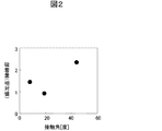
- the adsorption amount was small on the hydrophilic surface. This indicates that the pretreatment adsorbent can selectively adsorb organic components that are easily adsorbed to the reverse osmosis membrane by using a surface with a relatively high contact angle of 40 ° C. or more.
- the pretreatment adsorbent is used in water and adsorbs organic matter in water when it comes into contact with water. Therefore, on surfaces with a contact angle of 90 degrees or more where bubbles tend to form in the liquid, the organic matter contacts the membrane surface. It becomes difficult and the adsorption capacity decreases. For this reason, the contact angle must be in the range of 40 to 90 degrees.
- a material containing a carbonyl group, an amino group, etc. has a higher affinity with a reverse osmosis membrane-causing substance.
- examples include polyamide, polyimide, polyester, polycarbonate, polyurethane, acrylic resin, urea resin, polyethylene terephthalate, and the like.
- the main chain or the side chain contains a hydrocarbon having 4 or more carbon atoms or an aromatic ring.
- the thing containing a siloxane structure in a principal chain or a side chain is good for affinity with siloxanes.
- the structure contained in the main chain and the side chain is not limited to one type, and the adsorption efficiency can be improved by including a plurality of structures.
- the shape of the adsorbent may be particles, meshes, fibers, filters, etc., but is not limited thereto.
- the pretreatment adsorbent is a porous material such as a filter
- the surface area becomes particularly large. If the surface area of the adsorbent increases, the volume of equipment added to the pretreatment can be reduced, or the adsorbent can be installed in the tank of existing equipment.
- the porous body is a flat plate having a thickness of 10 ⁇ m to 5 mm, or has a shape of a filler in a certain space and has a communication hole inside so that water can pass therethrough.
- the porous material can be used as an adsorbent.
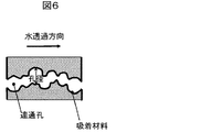
- FIG. 6 shows a schematic diagram of the communication holes of the porous material used as the adsorbent.
- the hole diameter when there is a hole from the surface with the porous body to the surface on the opposite side, the diameter in the direction substantially perpendicular to the direction in which water passes is defined as the hole diameter, and the average in-plane hole diameter is 5 to 200 ⁇ m.
- the average pore diameter is 5 ⁇ m or less, the resistance at the time of permeation of water becomes large and the amount of treated water cannot be obtained, or clogging due to components other than the adsorbed component is likely to occur.
- the average pore diameter is 200 ⁇ m or more, the effect of expanding the surface area due to the porous body is small and does not contribute to the volume control of the pretreatment equipment.
- the porous body Since the porous body has voids, the mechanical strength against water permeation may be insufficient and may not be able to stand by itself. In addition, when it is self-supporting, it may be compressed as the water permeates, and the communication hole may be deformed to reduce the amount of water permeated. Therefore, it is preferable to use a porous body and a support in combination. In particular, in the case of a plate-like porous body, water is permeated in the thickness direction of the porous body, and a support is installed in parallel to the plane of the porous body.
- the support allows water to pass without resistance, and when water is permeated at 0.1 MPa, the position change at the center of the long axis is within 5% with respect to the length of the fixed end in the long axis direction. It is sufficient that the material has a strength, a thickness, and a holding method that does not have an eluate in water.
- resin-based mesh spacers such as polyethylene, polypropylene, polyethylene terephthalate, and polystyrene, and metal-based stainless steels.
- Mesh such as titanium, punching metal, etc. are good.
- a porous body is formed by preparing a polyamide solution with a good solvent, such as a wet method or a precipitation method, and applying the solution to a substrate to form a film, which is then placed in high-humidity water vapor. Or adding a poor solvent to precipitate polyamide and replacing the good solvent with water or a poor solvent. In this case, a small hole diameter of 10 ⁇ m or less is formed.
- a foaming agent at the time of molding or adding fine particles of a soluble polymer or metal oxide later. In this case, a relatively large pore diameter of 10 ⁇ m or more is formed.
- the method for producing the porous membrane is not limited.
- FIG. 1 is a schematic view of a water treatment method according to the present invention.
- Sewage primary treated water is removed with dust on a screen, and fine suspensions such as sand are added to the water by adding flocculants and submerged, and decomposed using microorganisms, including suspended solids and dissolved organic matter. It is.
- the sewage primary treated water treated in this manner contains 5 to 20 mg / L of dissolved organic matter and electrolyte in terms of TOC (total organic carbon content).
- this sewage primary treated water is treated with a pretreatment adsorbent to adsorb and remove organic substances in the water.
- the electrolyte in the treated water is removed and the treatment is completed.
- the removed electrolyte is removed as concentrated water.
- Example 1 In each Example, the following materials were verified as pretreatment adsorbents for extending the life of the reverse osmosis membrane, and the results are summarized in FIGS. 4 and 5. Each Example and Comparative Example was performed as follows.
- Example 1 The following materials were verified as pretreatment adsorbents for extending the life of the reverse osmosis membrane, and the results are summarized in FIGS. 4 and 5.
- Example 2 Each Example and Comparative Example was performed as follows.
- Example 1 Example 1
- the material adsorption capacity was verified by the following method.
- polyamide shown in Chemical Formula 2 obtained by polymerizing m-phenylenediamine and terephthalic acid (shown in Chemical Formula 1) was used.
- This polyamide is one of the representative materials of the reverse osmosis membrane surface material.
- a hydrophilic polyvinylidene fluoride film was immersed in a 0.5% aqueous solution of m-phenylenediamine, pulled up, drained, and then immersed in a 0.1% n-hexane solution of benzophenone-4,4′-dicarboxylic acid, Pull up to drain. This was repeated 5 times to form a polymer film on the film surface.
- This polymer film is made of polyamide obtained by polymerizing m-phenylenediamine and terephthalic acid. The obtained film with a polymer film was washed with pure water and dried.
- Phenylalanine was selected as a model substance because it contains a carbonyl group and amino group, which are characteristic functional groups of organic substances that cause deterioration, and has strong affinity with the aromatic ring contained in the skeleton of the reverse osmosis membrane.
- a film with a polymer film made of m-phenylenediamine and benzophenone-4,4'-dicarboxylic acid is fixed to a bottom surface of a stainless steel pressure vessel in a 45 mm diameter circle, and 50 ml of phenylalanine 0.5% solution is added.
- the pressure of nitrogen gas was changed to 0.1 MPa, and the pressure was increased for 3 minutes to adsorb phenylalanine to the film. It was 1.9 mg when the density
- the water contact angle of the obtained polymer is 52 degrees, which is a range suitable for the adsorption of organic substances causing deterioration of the reverse osmosis membrane.
- the anti-contamination effect on the reverse osmosis membrane was confirmed as follows.
- the adsorbent was deposited on a slide glass. After the adsorbent is put into sewage primary treated water and stirred for 2 hours, the water is pressure filtered with a reverse osmosis membrane, the organic matter concentration in the water is measured with a TOC meter, and the amount of adsorption on the reverse osmosis membrane is Comparison was made with and without adsorbent.
- Example 2 In the same manner as in Example 1, a combination of m-phenylenediamine and benzophenone-4,4′-dicarboxylic acid (shown in Chemical Formula 4) as a material for the adsorbent surface was used to produce polyamide (shown in Chemical Formula 5) as Example 2. Then, the amount of adsorption and contact angle were measured.
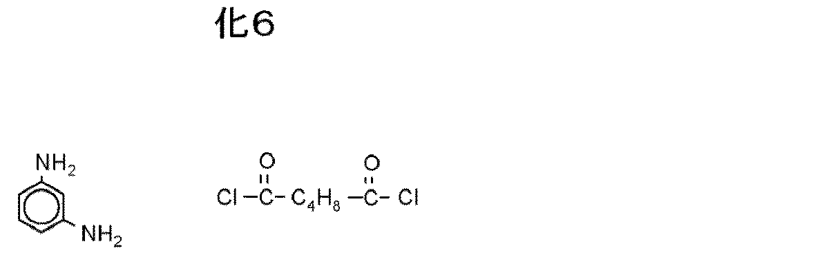
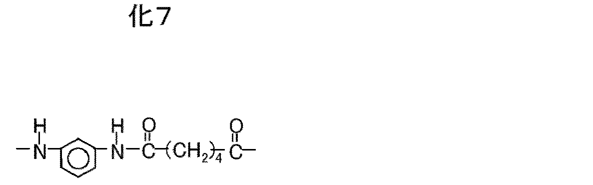
- Example 6 a combination of m-phenylenediamine and adipic acid chloride (shown in Chemical formula 6) was produced as Example 3 in polyamide (shown in Chemical formula 7), and the adsorbed amount was contacted. Corner measurements were taken.
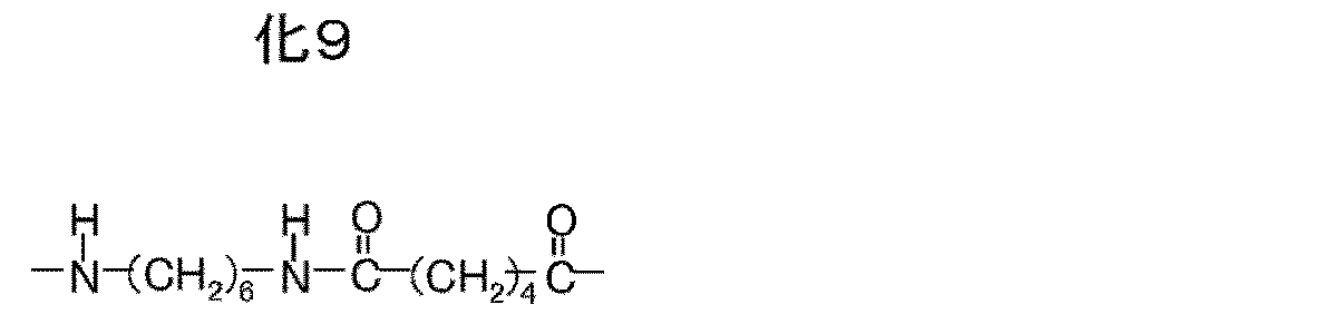
- Example 8 As a surface material for the adsorbent, a combination of 1,6-diaminohexane and adipic acid chloride (Chemical Formula 8) was prepared as Example 4 to produce a polyamide (shown in Chemical Formula 9). Corner measurements were taken.
- Example 2 the adsorption amount is 1.8 mg and the contact angle is 49 degrees. In Example 3, the adsorption amount is 1.4 mg and the contact angle is 54 degrees. In Example 4, the adsorption amount is 1.5 mg and the contact angle is 63 degrees. It became. (Comparative Example 1)
- Example 7 In order to evaluate the amount of adsorption of organic substances that cause deterioration of the reverse osmosis membrane on the hydrophilic surface, the amount of adsorption was measured in the same manner as in Example 1 using a hydrophilic polyvinylidene fluoride film. As a result, the adsorption amount was 0.9 mg, and the contact angle was 14 degrees. As shown in FIG. 4, the amount of adsorption is 50% or less as compared with Example 1, and the surface having high hydrophilicity is insufficient for use as an adsorbent. (Examples 5 to 7)
- Example 7 ⁇ ⁇ ⁇ ⁇ ⁇ ⁇ ⁇ Polyimide was studied as an adsorbing material. This is because two carbonyl groups are included per imide bond, and a high amount of poorly soluble organic matter can be expected.
- the materials examined were commercially available polyimide precursor solutions, PIX (registered trademark) L110SX (Example 5) manufactured by Hitachi Chemical Co., Ltd. and Sun Ever (registered trademark) 9441 (Example 6) manufactured by Nissan Chemical. As a control, the same polyamide as in Example 1 was examined as Example 7.
- the solution containing the adsorbing material was diluted and applied onto a glass substrate by spin coating, and then the solvent was dried at 70 ° C. and cured at 200 ° C. to produce an adsorbent on a flat plate.
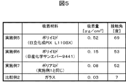
- the contact angle of the produced adsorbent was 69 degrees in Example 5 and 53 degrees in Example 6.
- the polyamide of Example 7 was prepared by immersing a glass substrate treated with a silane coupling agent having an amino group terminal in 0.1% n-hexane solution of benzophenone-4,4′-dicarboxylic acid, and pulling it up.
- the film was immersed in a 0.5% aqueous solution of m-phenylenediamine, pulled up and drained five times, and a polymer film was formed on the surface.
- the contact angle is 52 degrees.
- Example 5 0.52 ⁇ g / cm 2
- Example 6 is 0.15 [mu] g / cm 2
- Example 7 is 0.08 ⁇ g / cm 2
- the examples 5 and 6, compared with example 7 (the same material as in example 1) was found to be greater adsorption amount.
- Example 5 the anti-contamination effect on the reverse osmosis membrane was examined in the same manner as in Example 1. As a result, Example 5 showed an effect of 80% reduction and Example 6 an effect of 70% reduction.
- Comparative Example 2 As another comparative example of the hydrophilic surface, the amount of adsorption was measured on the glass surface in the same manner as in Example 7. As a result, the adsorption amount was 0.03 ⁇ g / cm 2 and the contact angle was 7 degrees.
- Example 8 As shown in FIG. 5, the amount of adsorption is 40% or less compared to Example 7, and the surface having high hydrophilicity is insufficient for use as an adsorbent. (Example 8)
- the surface area and cost of the adsorbent when the adsorbent is particulate were examined. If the adsorption capacity on the surface of the adsorbent is equivalent to that of reverse osmosis membrane, it can be used for pretreatment of reverse osmosis membrane with the same surface area.
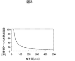
- the relationship between the particle diameter and the surface area is as shown in FIG.
- the vertical axis in FIG. 3 normalizes the obtained surface area with the reverse osmosis membrane surface area per module and converts it to the number of modules. That is, the number of reverse osmosis membrane modules that can be processed by one module filled with a pretreatment adsorbent of the same size as the reverse osmosis membrane module is shown.
- the larger the adsorbent diameter the easier it is to handle.
- the diameter of the adsorbent is large, the number of reverse osmosis membrane modules that can be processed per pretreatment adsorbent module decreases, and the addition of the pretreatment adsorbent increases the equipment volume. If 10 reverse osmosis membrane modules can be processed with at least one pretreatment adsorbent module, the adsorbent diameter is 250 ⁇ m or less.
- the material cost is estimated for the case where a sphere is made of an adsorbent material with a particle diameter of 100 ⁇ m, for example, and the case where an adsorbent material film is formed using inexpensive glass beads as a base material.
- the adsorbent material is 100 k ⁇
- the former costs about 10 times as much as the latter. Since this difference increases as the particle size increases, a method of forming a film having an adsorption function on a substrate is effective for a low-cost pretreatment adsorbent.
- a pre-treatment adsorbent is obtained by cutting a porous polyamide membrane with an average pore diameter of 5 ⁇ m and a thickness of 40 ⁇ m into a circular shape of 47 mm ⁇ , placing a stainless steel punching metal of the same diameter downstream as a support, and fixing it with an O-ring. It was created. 300 ml of primary treated water (total organic carbon amount 3.7 mg / L) subjected to biological treatment was circulated through the porous membrane of the pretreated adsorbent for 10 minutes, and then the total organic carbon amount was measured.
- the total amount of organic carbon in the water after passing through the porous membrane decreased to 3.2 mg / L, and a part of the organic matter was adsorbed on the porous membrane.
- the total amount of organic carbon in the water after passing through the porous membrane after contacting the surface of the reverse osmosis membrane was 3.2 mg / L, and the adsorption to the reverse osmosis membrane was below the measurement limit.
- the total amount of organic carbon in the water that does not pass through the porous membrane but contacted with the reverse osmosis membrane decreases to 3.4 mg / L. It turned out to be contaminated.
- the polyamide porous membrane adsorbent can prevent the reverse osmosis membrane from being contaminated.
Landscapes
- Water Supply & Treatment (AREA)
- Engineering & Computer Science (AREA)
- Chemical & Material Sciences (AREA)
- Hydrology & Water Resources (AREA)
- Chemical Kinetics & Catalysis (AREA)
- Life Sciences & Earth Sciences (AREA)
- Nanotechnology (AREA)
- Environmental & Geological Engineering (AREA)
- Organic Chemistry (AREA)
- Separation Using Semi-Permeable Membranes (AREA)
- Water Treatment By Sorption (AREA)
- Solid-Sorbent Or Filter-Aiding Compositions (AREA)
- Activated Sludge Processes (AREA)
Abstract
水処理プラントにおいて,高度処理に用いられる逆浸透膜表面に水中溶解有機物が吸着して膜性能を劣化させ,逆浸透膜モジュールの交換頻度が高いことが課題である。この課題に対し、逆浸透膜を劣化させる原因有機物はカルボニル基を持ち,接触角40度以上の表面に吸着するので,原因有機物を選択的に吸着する疎水性の前処理吸着剤により,逆浸透膜前であらかじめ原因有機物を除去し,逆浸透膜の交換頻度を低くする。前処理吸着剤の材料は,高分子の結合部位にカルボニル基を持つことで,原因有機物を選択的に吸着することができる。
Description
本発明は,下水の高度処理に用いる水中溶解有機物および電解質を分離除去する逆浸透膜の前処理技術に関する。
水の浄化の高度処理において逆浸透膜が用いられている。逆浸透膜表面には半透膜が用いられるが,半透膜の材質は大きく分けて,酢酸セルロース系と芳香族ポリアミド系がある。このうち,芳香族ポリアミド系の逆浸透膜は水透過性や電解質除去性能が高いため,工業用に広く用いられている。その構造は,微孔多孔質支持体上に芳香族ポリアミド膜を形成した複合半透膜の構造が多く用いられ,芳香族ポリアミド部分の膜厚は1μm以下である。
逆浸透膜は海水淡水化,半導体等の精密電子機器製造に用いる純水製造,上水の高度処理,下水・排水の最終処理などに水中溶解する有機物,電解質の除去に用いられる。
これらの用途のうち,下水の最終処理に用いる場合は,一般的に以下のような処理プロセスを経て水が逆浸透膜に供給される。まず,下水に含まれる粗大な夾雑物,ごみ等はスクリーンと呼ばれるふるいを通して除かれる。次に,砂などの細かい懸濁物を必要に応じて凝集剤等を添加し沈殿池で沈下させ分離する。上澄みの水にはまだ浮遊物や溶解有機物等が含まれており,微生物を用いて分解する。微生物の代謝物が汚泥として発生し,汚泥と水は沈殿池での沈降または精密ろ過膜を通すことで分離される。このようにして処理された下水一次処理水には浮遊物はほとんど含まれず,この段階で消毒等を行って,河川に放流できる水質まで浄化されている。日本国内では,この段階で河川に放流し自然浄化を活かして,水循環を行っている。しかしながら,中東,大陸内陸部,河川のない島等では自然浄化に必要十分な河川や湖沼がないために,下水一次処理水をさらに浄化して飲料水や工業用水として再利用する要望が高まっている。逆浸透膜はこの最終処理において下水一次処理水中の溶解有機物や電解質を除去するのに用いられる。
下水一次処理水には,前段階までの処理などによって変化するが,有機物がTOC(全有機炭素量)に換算して5~20mg/L含まれる。これらを逆浸透膜で分離すると有機物を1mg/L以下まで低下させることが可能である。
下水最終処理に用いられる逆浸透膜は,モジュール内の膜表面積を増加させるため,スパイラルと呼ばれる形状に折りたたまれているものが多い。中央の芯の部分に袋状の逆浸透膜を固定し,傘のように巻き上げて円筒に納めた形をしている。モジュールは4インチ,8インチなどの直径で長さが1mの円筒形が主流である。
逆浸透膜は,分離膜の一種であるが,分離膜を用いた水のろ過方式には2方式ある。一つは,全量ろ過方式で,これは供給した水の全量を膜に通過させる方式で,膜を通過できない成分は膜面に堆積する。もう一つはクロスフローろ過方式であり,膜面に平行に水が流れ,一部が膜を透過して透過水に,残りは溶解物濃度が高くなった状態で濃縮水としてモジュールから取り出される。逆浸透膜でのろ過には,後者のクロスフローろ過方式を用いている。この方式では,膜表面への溶解物の析出や濃度上昇による運転負荷上昇を低減する。しかし,クロスフローろ過方式でも溶解物が膜面に吸着し,透過水量が経時的に劣化する問題がある。
膜面への吸着物には,電解質が膜面付近で濃度が高くなって析出するスケール,水中の微生物が膜面で増殖するバイオファウリングなどのほか,有機物が吸着する有機物ファウリングがある。定期的に膜面に清浄水を流し,せん断力によって吸着物を除去しているが,有機物が吸着した場合,せん断力では完全に除去することができず,徐々に蓄積して逆浸透膜モジュールを交換する必要が生じる。逆浸透膜モジュールの交換時は運転を長時間止める必要があり,また逆浸透膜モジュールは再生利用ができないため,新しい逆浸透膜モジュールに交換する必要があり,ランニングコストをあげる原因となっている。
このため,有機物を逆浸透膜前であらかじめ除去する前処理を追加して逆浸透膜の交換までの寿命を延ばす方法がある。前処理方法としては,有機物を分解する方法,有機物を吸着や凝集により,除去する方法などがあるが,後者の有機物を吸着する方法としては,特許文献1には,逆浸透膜と同じ材料からなる吸着剤を用いる方法が開示されている。また,特許文献2には,溶解有機物のうち親水性のものを吸着除去する方法が開示されている。
有機物の吸着剤としては活性炭が有名である。しかしながら,活性炭を用いる方法では
,下水一次処理水に含まれる有機物のほとんどを吸着するために,活性炭の交換頻度が高くなり,逆浸透膜の交換頻度を低減してもコストメリットが得られない。
,下水一次処理水に含まれる有機物のほとんどを吸着するために,活性炭の交換頻度が高くなり,逆浸透膜の交換頻度を低減してもコストメリットが得られない。
下排水の再生処理プロセスにおいて生物活性汚泥処理後に逆浸透膜を用いて処理する場合に,逆浸透膜表面に水中に溶解した難分解性有機物が吸着して通水率が経時劣化する問題がある。劣化した逆浸透膜の表面を清浄な水で洗浄して性能を回復するが,完全な機能回復は難しいため,逆浸透膜を交換する必要がある。逆浸透膜の寿命が短いと水処理のランニングコストが高くなる。前処理で有機物を除去する方法があるが,低コストで効果を得ることが難しい。
本発明の目的は,上記課題を解決し,低コストな前処理を追加して逆浸透膜の寿命を延ばし,下排水の再生処理にかかるランニングコストを低減することである。
逆浸透膜に供給される下水一次処理水は微生物による有機物分解処理後の水であり,難分解性有機物がTOC(全有機炭素量)に換算して5~20mg/L含まれる。難分解性有機物の種類は1つに特定できるものではない。クロスフローろ過方式においては,逆浸透膜で分離された成分は濃縮水とともに排出されるので,排出可能な有機物は逆浸透膜の劣化原因ではなく,積極的に除去する必要はない。図1に示す水処理フローにより,逆浸透膜表面に吸着する有機物のみを選択的に効率よく吸着除去する前処理吸着剤により,課題を解決する。
まず,逆浸透膜の表面への吸着有機物を分析した。多成分が含まれるので,成分を特定できるものではないが,カルボニル基を含む有機物が吸着しやすいことが分かった。他に,Siを含むシロキサン類,アミノ基を含む成分なども吸着する成分に含まれる。
また,逆浸透膜への難分解性有機物の吸着量を調べたところ,水中に含まれる難分解性有機物のうち,逆浸透膜に吸着するのはTOC換算して5%程度でそれ以外の有機物は水中に存在しても逆浸透膜に吸着せず,通水率劣化原因とはならないことを突き止めた。
次に,逆浸透膜の表面状態と有機物の吸着量の関係を調べるため,親水性すなわち水の接触角を変化させた逆浸透膜を準備し,膜への有機物吸着量を調べたところ,図2に示すように,親水性の表面では吸着量が小さくなることを突き止めた。このことから,前処理吸着剤は,比較的疎水性の高い接触角40度以上の表面とすることで,逆浸透膜に吸着しやすい有機物成分を選択的に吸着できることが分かった。
一方で,前処理吸着剤は水中で用い,水と接触することで水中の有機物を吸着するので,液中で気泡を生じやすくなる接触角90度以上の表面では,有機物が膜表面に接触しにくくなり吸着能力が低下する。このため,接触角は40~90度の範囲とする必要がある。
逆浸透膜が有機物を吸着するメカニズムには大きく2つがあると言われている。1つは分子間相互作用で,分子構造の似た材料どうしに親和力が働く。吸着物の分析から,カルボニル基,アミノ基等を含む材質が,逆浸透膜劣化原因物質との親和力が高くなると考えられるので,カルボニル基やアミノ基を繰り返し単位に含む高分子が良い。一例として,ポリアミド,ポリイミド,ポリエステル,ポリカーボネート,ポリウレタン,アクリル樹脂,尿素樹脂,ポリエチレンテレフタレート,などがある。接触角を40度以上にするためには,主鎖や側鎖に炭素数4以上の炭化水素や芳香環を含むものが良い。また,シロキサン類との親和力のため,主鎖または側鎖にシロキサン構造を含むものも良い。さらに,主鎖や側鎖に含まれる構造は1種類に限らず,複数の構造を含むことによって,吸着効率
を向上することができる。
を向上することができる。
逆浸透膜表面と同等の吸着能力がある吸着表面を持つ前処理吸着剤があるとき,逆浸透膜に投入する前に逆浸透膜と同じ表面積以上の前処理吸着剤に接触させると劣化原因となる有機物を除去して,逆浸透膜の寿命を2倍化することが可能である。吸着剤の表面積を大きくするため,吸着剤の形状としては,粒子,メッシュ,繊維,フィルタなどが考えられるが,限定されるものではない。
前処理吸着剤がフィルタなどの多孔質体の場合に,特に表面積が大きくなる。吸着剤の表面積が大きくなると,前処理に追加する設備の体積が抑えられたり,または既存設備のタンク内に吸着剤を設置したりが可能となる。ここで,多孔質体とは,厚さが10μm~5mmの平板状のもの,もしくは,ある空間内の充填材の形状を有し,水が通過できるように内部に連通孔をもつものであり,この多孔質体は吸着剤の用途として用いることができる。
吸着剤として用いる多孔質体の連通孔の模式図を図6に示す。図6のように多孔質体のある面から反対側の面までの孔があったとき,水が通過する方向とほぼ垂直方向の径を孔径と定義し,面内の平均孔径が5~200μmのものが吸着剤として適する。平均孔径5μm以下では水の透過時の抵抗が大きくなって処理水量が得られなかったり,吸着成分以外の成分による目詰まり発生が起きやすくなったりする。一方,平均孔径200μm以上では,多孔質体にしたことによる表面積拡大の効果が小さく,前処理設備の体積抑制に寄与しない。
多孔質体は空隙があるため,水の透過に対する機械強度が不十分で自立できない場合がある。また,自立する場合も水の透過に伴って圧縮され,連通孔が変形して水の透過量が低下する場合がある。そのため,多孔質体と支持体を併用することが好ましい。とくに平板状の多孔質体の場合は,多孔質体の厚さ方向に水を透過させ,多孔質体の平面と平行に支持体を設置する。
支持体は水が抵抗なく通過可能で,水を0.1MPaで透過させたときに,固定端の長軸方向の長さに対して,長軸の中央部での位置変化が5%以内となる強度を持つような素材,厚さ,保持方法で,水への溶出物がない材質であれば良く,例えば,樹脂系ではポリエチレン,ポリプロピレン,ポリエチレンテレフタレート,ポリスチレン等のメッシュスペーサ,金属系ではステンレス,チタンなどのメッシュ,パンチングメタル等が良い。
多孔質体の形成方法は,例えばポリアミドの場合,湿式法や析出法などの,良溶媒でポリアミド溶液を調製し,溶液を基材に塗布して膜としたあと,高湿度の水蒸気内に入れたり,貧溶媒を添加したりしてポリアミドを析出させるとともに良溶媒を水や貧溶媒に置換する方法がある。この場合は10μm以下の小さい孔径が形成される。または,成形時に発泡剤を入れたり,あとから溶解可能なポリマーや金属酸化物の微粒子を加える方法もあり,この場合は10μm以上の比較的大きい孔径が形成される。しかし,多孔膜の製造方法に限定を加えるものではない。
また,あらかじめ多孔質の基材表面に吸着機能を持つ材料を修飾する方法もある。吸着剤は表面のみが劣化原因有機物の吸着に寄与する。吸着剤をすべて吸着機能材料で形成すると,吸着剤部材コストが高くなるので,吸着剤の形状は低コストなガラス,汎用合成樹脂などの基材で形成し,最表面を吸着機能材料で被覆した構造とする。このとき,基材と吸着機能材料の結合を強固なものとするための接着層や反応開始層を基材と吸着機能材料の間に形成しても良い。
このような吸着剤により,逆浸透膜前処理を行うことで,あらかじめ逆浸透膜の性能劣化原因の有機物のみを選択的に吸着して水中から除去することができ,また,吸着剤への有機物蓄積量が少ないため,吸着剤の交換頻度が低く,吸着機能を最表面だけに限定することで低コストな前処理方法が得られる。
本発明によれば,低コストな前処理を追加して逆浸透膜の寿命を延ばすことにより,下排水の再生処理にかかるランニングコストを低減することが可能である。
以下,実施例を用いて説明する。
図1は,本発明にかかる水処理方法の概略図である。下水一次処理水は,ごみ等をスクリーンにかけて取り除かれ,さらに砂などの細かい懸濁物を凝集剤等を添加し沈下させ,微生物を用いて分解した水でり,浮遊物や溶解有機物等が含まれている。このように処理された下水一次処理水は,溶解有機物や電解質をTOC(全有機炭素量)に換算して5~20mg/L含まれる。
本発明にかかる水処理では,この下水一次処理水を前処理吸着剤を用いて処理し,水中の有機物を吸着除去する。
さらに,前処理を行った処理水を圧力をかけながら逆浸透膜を通すことで,処理水中の電解質を除去され,処理が完成する。除去された電解質は,濃縮水として取り除かれる。
各実施例では,逆浸透膜の寿命を延ばすための前処理吸着剤として,以下の材料の検証を行い,その結果を図4及び図5にまとめた。各々の実施例及び比較例は,以下のように行った。
(実施例1)
(実施例1)
材料の吸着能力について,以下の方法で検証した。吸着剤表面材質として,m-フェニレンジアミンとテレフタル酸(化1に示す)を重合したポリアミド(化2に示す)を用いた。


このポリアミドは逆浸透膜の表面材料の代表的な材料の1つである。
親水化したポリフッ化ビニリデンのフィルムをm-フェニレンジアミンの0.5%水溶液に浸漬し,引き上げて液切後,ベンゾフェノン-4,4’-ジカルボン酸0.1%n-ヘキサン溶液に浸漬し,引き上げて液切する。これを5回繰り返し,フィルム表面に高分子膜を形成した。この高分子膜は,m-フェニレンジアミンとテレフタル酸を重合したポリアミドにより構成されている。得られた高分子膜付きフィルムは純水洗浄し,乾燥した。
一方,逆浸透膜の劣化原因有機物のモデル物質として,アミノ酸の1つであるフェニルアラニンの0.05%水溶液を準備した(化3に示す)。

フェニルアラニンは劣化原因有機物の特徴的な官能基であるカルボニル基,アミノ基を含み,また,逆浸透膜の骨格に含まれる芳香環との親和力も強いため,モデル物質として選定した。
ステンレス製加圧容器の底面にm-フェニレンジアミン,ベンゾフェノン-4,4’-ジカルボン酸から成る高分子膜の形成されたフィルムを45mm径の円形にして固定し,フェニルアラニン0.5%溶液50mlを加えて,窒素ガスの圧力により大気圧との差圧を0.1MPaにして3分間加圧してフィルムにフェニルアラニンを吸着させた。吸着前後のフェニルアラニン溶液の濃度をTOC計で測定し,濃度差から吸着量を算出したところ,1.9mgであった。
また,得られた高分子の水接触角は52度となり,逆浸透膜の劣化原因有機物の吸着に適した範囲である。
逆浸透膜への汚染防止効果について,以下のように確認した。吸着剤をスライドガラス上に成膜した。吸着剤を下水一次処理水中に入れて2時間攪拌したのちに,その水を逆浸透膜で加圧ろ過して,水中の有機物濃度をTOC計で測定し,逆浸透膜への吸着量を,吸着剤がある場合とない場合とで比較した。その結果,吸着剤がある場合はない場合に比べて逆浸透膜への吸着量が60%減少し,逆浸透膜の劣化原因有機物を吸着除去する効果が確かめられた。このとき,吸着剤表面積と逆浸透膜表面積は同じ面積となるようにした。
(実施例2~4)
(実施例2~4)
実施例1と同じ方法で,吸着剤表面材質として,m-フェニレンジアミンとベンゾフェノン-4,4’-ジカルボン酸(化4に示す)の組合せを実施例2としてポリアミド(化5に示す)を作製し,吸着量と接触角の測定を行った。


実施例1と同じ方法で,吸着剤表面材質として,m-フェニレンジアミンとアジピン酸クロリド(化6に示す)の組合せを実施例3としてポリアミド(化7に示す)を作製し,吸着量と接触角の測定を行った。
実施例1と同じ方法で,吸着剤表面材質として,1,6-ジアミノヘキサンとアジピン酸クロリド(化8)の組合せを実施例4としてポリアミド(化9に示す)を作製し,吸着量と接触角の測定を行った。

実施例2では吸着量が1.8mg,接触角は49度,実施例3では吸着量が1.4mg,接触角が54度,実施例4は吸着量が1.5mg,接触角が63度となった。(比較例1)
親水化表面への逆浸透膜の劣化原因有機物の吸着量を評価するため,親水化ポリフッ化ビニリデンのフィルムを用いて,実施例1と同様に吸着量を測定した。その結果,吸着量は0.9mg,接触角は14度であった。図4に示すとおり,実施例1に比べて吸着量が50%以下であり,親水性の高い表面は吸着剤として用いるには吸着量が不十分である。
(実施例5~7)
(実施例5~7)
吸着材料としてポリイミドを検討した。イミド結合一つ当たりにカルボニル基が二つ含まれており,高い難溶解性有機物の吸着量が期待できるからである。検討した材料は市販のポリイミド前駆体溶液で,日立化成製PIX(登録商標) L110SX(実施例5)と日産化学製サンエバー(登録商標)9441(実施例6)である。また,対照として実施例1と同じポリアミドを実施例7として検討した。
吸着材料を含む溶液を希釈し,ガラス基板上にスピンコートで塗布後,70℃で溶剤を乾燥し,200℃で硬化して平板上の吸着剤を作製した。作製した吸着剤の接触角は,実施例5が69度,実施例6が53度であった。
一方,実施例7のポリアミドは,アミノ基末端をもつシランカップリング剤で処理したガラス基板をベンゾフェノン-4,4’-ジカルボン酸0.1%n-ヘキサン溶液に浸漬し,引き上げて液切後,m-フェニレンジアミンの0.5%水溶液に浸漬し,引き上げて液切することを5回繰り返し,表面に高分子膜を形成した。接触角は52度である。
これらの表面に,逆浸透膜へ供給される下水一次処理水を流してその吸着量を測定した。その結果,0.2ml/分で供給したときの5分後の吸着量は,実施例5が0.52μg/cm2,実施例6が0.15μg/cm2,実施例7が0.08μg/cm2となり,実施例5,6は,実施例7(実施例1と同じ材料)に比べ,吸着量が多くなることが分かった。
実施例5,6について,逆浸透膜への汚染防止効果を実施例1と同様に調べたところ,実施例5では80%低減,実施例6では70%低減の効果が得られた。
(比較例2)
親水化表面のその他の比較例として,ガラス表面について,実施例7と同様に吸着量を測定した。その結果,吸着量は0.03μg/cm2,接触角は7度であった。
親水化表面のその他の比較例として,ガラス表面について,実施例7と同様に吸着量を測定した。その結果,吸着量は0.03μg/cm2,接触角は7度であった。
図5に示す通り,実施例7に比べて吸着量が40%以下であり,親水性の高い表面は吸着剤として用いるには吸着量が不十分である。
(実施例8)
(実施例8)
吸着剤が粒子状の場合の吸着剤表面積やコストを検討した。吸着剤表面の吸着能力が逆浸透膜と同等の場合,同じ表面積の逆浸透膜の前処理に使用可能である。多孔質体でない球状粒子を最密充填の50%つまり空間占有率37%で,逆浸透膜のモジュールと同一サイズに充填したとき,粒子径と表面積の関係は図3のようになる。図3の縦軸は得られた表面積を,モジュール1本あたりの逆浸透膜表面積で規格化して,モジュール本数に換算している。つまり,逆浸透膜モジュールと同一サイズの前処理吸着剤を充填したモジュール1本で処理できる逆浸透膜モジュール本数を表している。
吸着剤を取り扱うには,吸着剤の径が大きいほうが取り扱いやすい。一方,吸着剤の径が大きいと前処理吸着剤モジュール1本あたりに処理できる逆浸透膜モジュール本数が減り,前処理吸着剤の追加によって設備体積が大きくなる。少なくとも前処理吸着剤モジュール1本で10本の逆浸透膜モジュールが処理できるとすると吸着剤直径は250μm以下となる。
この吸着剤の直径の範囲内で,例として100μmの粒子径で,吸着剤材料で球を作製した場合と,安価なガラスビーズを基材として,吸着材料膜を形成したもので材料コストを見積もったところ,吸着剤材料が100k¥のときに,前者は後者に比べ約10倍材料コストが高い。粒子径が大きくなるほど,この差が大きくなるので,低コストの前処理吸着剤には基材の上に吸着機能を持つ膜を形成する方法が有効である。
(実施例9)
(実施例9)
平均孔径が5μm,厚さが40μmのポリアミド多孔膜を47mmφの円形に切断し,下流側に同じ径のステンレスのパンチングメタルを支持体として設置し,Oリングで固定することにより,前処理吸着剤を作成した。生物処理を行った下水の一次処理水(全有機炭素量3.7mg/L)300mlをこの前処理吸着剤の多孔膜に10分間循環して通過させた後に,全有機炭素量を測定した。別途同様に一次処理水300mlを多孔膜に10分間循環したのちに,通過後の水を100mm角の逆浸透膜表面に接触させて4時間攪拌しながら放置した。このとき,逆浸透膜には加圧せず,水をろ過することはしていない。処理後の水の全有機炭素量を測定した。さらに,比較対照としてポリアミド多孔膜を通過させずに逆浸透膜に接触させた一次処理水の全有機炭素量も測定した。
その結果,多孔膜に通過後の水の全有機炭素量は3.2mg/Lに減少しており,有機物の一部が多孔膜に吸着したことが分かった。また,多孔膜に通過後の水を逆浸透膜表面に接触した後の水の全有機炭素量は3.2mg/Lであり,逆浸透膜への吸着は測定限界以下であった。一方,多孔膜に通過せずに逆浸透膜に接触させた水の全有機炭素量は3.4mg/Lに減少し,吸着処理をしない場合は,有機物の一部が逆浸透膜表面に吸着汚染していることが判明した。これによりポリアミド多孔膜吸着剤によって,逆浸透膜の汚染防止が可能であることが示された。
Claims (15)
- 被処理水を,逆浸透膜処理する水処理方法において,
前記生物分解処理の後であり前記逆浸透膜処理の前に,表面材質が前記逆浸透膜よりも疎水性が高い水処理部材に前記被処理水を接触させる処理を行うことを特徴とする水処理方法。 - 前記水処理部材は,表面材質の高分子の結合部位にカルボニル基を有する水処理部材であることを特徴とする請求項1に記載の水処理方法。
- 前記水処理部材は,表面の材料が,イミド結合を有するポリイミドであることを特徴とする請求項2に記載の水処理方法。
- 前記水処理部材は,表面の材料が,アミド結合を有するポリアミドであることを特徴とする請求項2に記載の水処理方法。
- 前記水処理部材の表面材質の材料が,その繰り返し単位にアミノ基,芳香環,炭素数4以上のアルキル鎖のいずれかもしくは複数を含むことを特徴とする請求項1に記載の水処理方法。
- 前記水処理部材の表面材質を平板上に形成したとき,その水の接触角が40度~90度であることを特徴とした請求項1に記載の水処理方法。
- 前記水処理部材は,水が通過可能な連通孔を有する多孔体であり,当該連通孔の平均孔径は5~200μmであることを特徴とする請求項2に記載の水処理方法。
- 前記水処理部材が,前記多孔体と,当該多孔体を支持する支持体とを有することを特徴とする請求項7に記載の水処理方法。
- 被処理水を,生物分解処理した後に逆浸透膜処理する水処理で,前記生物分解処理の後であり前記逆浸透膜処理の前に,前記被処理水に接触させる水処理部材であって,
表面の材料が逆浸透膜よりも疎水性が高いことを特徴とする水処理部材。 - 表面の材料の高分子の結合部位にカルボニル基を有する水処理部材であることを特徴とする請求項9に記載の水処理部材。
- 表面の材料が,イミド結合を有するポリイミドであることを特徴とする請求項9に記載の水処理部材。
- 表面の材料が,アミド結合を有するポリアミドであることを特徴とする請求項9に記載の水処理部材。
- 表面の材料が,その繰り返し単位にアミノ基,芳香環,炭素数4以上のアルキル鎖のいずれかもしくは複数を含むことを特徴とする請求項9に記載の水処理部材。
- 前記表面の材料を平板上に形成したとき,その水の接触角が40度~90度であることを特徴とした請求項9に記載の水処理部材。
- 前記表面の材料が,水が通過可能な連通孔を有し,当該連通孔の平均孔径5~200μmの多孔体であることを特徴とする請求項9に記載の水処理部材。
Priority Applications (1)
| Application Number | Priority Date | Filing Date | Title |
|---|---|---|---|
| CN201080004153.3A CN102272052B (zh) | 2009-03-10 | 2010-02-15 | 水处理方法、水处理部件以及水处理设备 |
Applications Claiming Priority (4)
| Application Number | Priority Date | Filing Date | Title |
|---|---|---|---|
| JP2009-055886 | 2009-03-10 | ||
| JP2009055886 | 2009-03-10 | ||
| JP2009-269434 | 2009-11-27 | ||
| JP2009269434A JP5581669B2 (ja) | 2009-03-10 | 2009-11-27 | 水処理方法、水処理部材及び水処理設備 |
Publications (1)
| Publication Number | Publication Date |
|---|---|
| WO2010103731A1 true WO2010103731A1 (ja) | 2010-09-16 |
Family
ID=42728030
Family Applications (1)
| Application Number | Title | Priority Date | Filing Date |
|---|---|---|---|
| PCT/JP2010/000890 Ceased WO2010103731A1 (ja) | 2009-03-10 | 2010-02-15 | 水処理方法及び水処理部材 |
Country Status (3)
| Country | Link |
|---|---|
| JP (1) | JP5581669B2 (ja) |
| CN (1) | CN102272052B (ja) |
| WO (1) | WO2010103731A1 (ja) |
Families Citing this family (4)
| Publication number | Priority date | Publication date | Assignee | Title |
|---|---|---|---|---|
| JP2012196590A (ja) * | 2011-03-18 | 2012-10-18 | Asahi Kasei Chemicals Corp | ろ過膜、ろ過膜の洗浄手段および前処理手段の選択方法 |
| JP6164366B2 (ja) * | 2014-06-27 | 2017-07-19 | 日立金属株式会社 | 吸着部材 |
| MY204719A (en) * | 2018-03-15 | 2024-09-11 | Toray Industries | Fluid separation membrane |
| CN112266496B (zh) * | 2020-10-29 | 2023-01-20 | 江苏厚生新能源科技有限公司 | 一种基于聚酰亚胺改性的多层复合膜及其制备工艺 |
Citations (8)
| Publication number | Priority date | Publication date | Assignee | Title |
|---|---|---|---|---|
| JPS59123584A (ja) * | 1982-12-28 | 1984-07-17 | Yamamura Kagaku Kenkyusho:Kk | 水の精製方法 |
| JPS6146203A (ja) * | 1984-08-09 | 1986-03-06 | Nitto Electric Ind Co Ltd | 複合半透膜及びその製造方法 |
| JPH0338229A (ja) * | 1989-07-05 | 1991-02-19 | Mitsubishi Kasei Corp | ポリイミド分離膜 |
| JPH04305287A (ja) * | 1991-04-01 | 1992-10-28 | Kubota Corp | 水処理設備 |
| JPH1190500A (ja) * | 1997-09-25 | 1999-04-06 | Mitsubishi Rayon Co Ltd | 汚泥の処理方法 |
| JPH11333454A (ja) * | 1998-01-19 | 1999-12-07 | Nikkiso Co Ltd | 油性溶質吸着体及び浄水器 |
| JP2008207077A (ja) * | 2007-02-23 | 2008-09-11 | Ngk Insulators Ltd | インク含有排水の処理方法 |
| JP2008246386A (ja) * | 2007-03-30 | 2008-10-16 | Kurita Water Ind Ltd | 有機性排水の処理装置 |
Family Cites Families (2)
| Publication number | Priority date | Publication date | Assignee | Title |
|---|---|---|---|---|
| JPH07105357B2 (ja) * | 1989-01-28 | 1995-11-13 | 国際電気株式会社 | 縦型cvd拡散装置に於けるウェーハ移載方法及び装置 |
| JPH11314087A (ja) * | 1998-05-06 | 1999-11-16 | Nikkiso Co Ltd | 高清浄水製造装置 |
-
2009
- 2009-11-27 JP JP2009269434A patent/JP5581669B2/ja not_active Expired - Fee Related
-
2010
- 2010-02-15 WO PCT/JP2010/000890 patent/WO2010103731A1/ja not_active Ceased
- 2010-02-15 CN CN201080004153.3A patent/CN102272052B/zh not_active Expired - Fee Related
Patent Citations (8)
| Publication number | Priority date | Publication date | Assignee | Title |
|---|---|---|---|---|
| JPS59123584A (ja) * | 1982-12-28 | 1984-07-17 | Yamamura Kagaku Kenkyusho:Kk | 水の精製方法 |
| JPS6146203A (ja) * | 1984-08-09 | 1986-03-06 | Nitto Electric Ind Co Ltd | 複合半透膜及びその製造方法 |
| JPH0338229A (ja) * | 1989-07-05 | 1991-02-19 | Mitsubishi Kasei Corp | ポリイミド分離膜 |
| JPH04305287A (ja) * | 1991-04-01 | 1992-10-28 | Kubota Corp | 水処理設備 |
| JPH1190500A (ja) * | 1997-09-25 | 1999-04-06 | Mitsubishi Rayon Co Ltd | 汚泥の処理方法 |
| JPH11333454A (ja) * | 1998-01-19 | 1999-12-07 | Nikkiso Co Ltd | 油性溶質吸着体及び浄水器 |
| JP2008207077A (ja) * | 2007-02-23 | 2008-09-11 | Ngk Insulators Ltd | インク含有排水の処理方法 |
| JP2008246386A (ja) * | 2007-03-30 | 2008-10-16 | Kurita Water Ind Ltd | 有機性排水の処理装置 |
Also Published As
| Publication number | Publication date |
|---|---|
| JP2010234353A (ja) | 2010-10-21 |
| JP5581669B2 (ja) | 2014-09-03 |
| CN102272052A (zh) | 2011-12-07 |
| CN102272052B (zh) | 2014-11-26 |
Similar Documents
| Publication | Publication Date | Title |
|---|---|---|
| Ladewig et al. | Fundamentals of membrane bioreactors | |
| Shon et al. | Nanofiltration for water and wastewater treatment–a mini review | |
| Yan et al. | Application of the Al2O3–PVDF nanocomposite tubular ultrafiltration (UF) membrane for oily wastewater treatment and its antifouling research | |
| Wu et al. | Treatment of oily water by a poly (vinyl alcohol) ultrafiltration membrane | |
| Chen et al. | Hierarchical poly (vinylidene fluoride)/active carbon composite membrane with self-confining functional carbon nanotube layer for intractable wastewater remediation | |
| Kim et al. | Effects of wastewater effluent organic materials on fouling in ultrafiltration | |
| Kumar et al. | Emerging trends in membrane-based wastewater treatment: electrospun nanofibers and reticular porous adsorbents as key components | |
| US20120118824A1 (en) | Water treatment apparatus and water treatment method | |
| JP5581669B2 (ja) | 水処理方法、水処理部材及び水処理設備 | |
| Zhao et al. | Factors causing PAC cake fouling in PAC–MF (powdered activated carbon-microfiltration) water treatment systems | |
| JPWO2008096585A1 (ja) | ろ過装置および水処理方法 | |
| Gorjizadeh et al. | Surface modification of membrane bioreactor by hybrid halloysite nanotubes for industrial wastewater treatment containing heavy metals | |
| JP2009072766A (ja) | 水処理方法 | |
| AU2009230315B2 (en) | Method for purification treatment of process water | |
| WO2017159303A1 (ja) | 高硬度排水の処理方法 | |
| Kumar et al. | Case Studies (Success Stories) on the Application of Metal‐Organic Frameworks (MOF s) in Wastewater Treatment and Their Implementations; Review | |
| Zhu et al. | Pre-ozonation for dead-end microfiltration of the secondary effluent: suspended particles and membrane fouling | |
| Lee et al. | Development of an integrated iron oxide adsorption/membrane separation system for water treatment | |
| Madaeni et al. | Membrane‐adsorption integrated systems/processes | |
| Thiruvenkatachari et al. | Effect of powdered activated carbon type on the performance of an adsorption-microfiltration submerged hollow fiber membrane hybrid system | |
| Chakraborty et al. | Recent advances in membrane technology for the recovery and reuse of valuable resources | |
| Mohammed et al. | Treatment of power plant wastewater using reverse osmosis process | |
| KR100626321B1 (ko) | 오염도가 낮은 분리막 및 그것의 제조방법 | |
| KR100829078B1 (ko) | 동적막을 이용한 수처리 방법 및 그 장치 | |
| CN210410244U (zh) | 一种氨基化氧化石墨烯与石墨相氮化碳复合改性膜 |
Legal Events
| Date | Code | Title | Description |
|---|---|---|---|
| WWE | Wipo information: entry into national phase |
Ref document number: 201080004153.3 Country of ref document: CN |
|
| 121 | Ep: the epo has been informed by wipo that ep was designated in this application |
Ref document number: 10750490 Country of ref document: EP Kind code of ref document: A1 |
|
| NENP | Non-entry into the national phase |
Ref country code: DE |
|
| 122 | Ep: pct application non-entry in european phase |
Ref document number: 10750490 Country of ref document: EP Kind code of ref document: A1 |