WO2010101172A1 - 無線通信システム、受信装置、送信装置、無線通信システムの通信方法、制御プログラムおよび自律分散型ネットワーク - Google Patents
無線通信システム、受信装置、送信装置、無線通信システムの通信方法、制御プログラムおよび自律分散型ネットワーク Download PDFInfo
- Publication number
- WO2010101172A1 WO2010101172A1 PCT/JP2010/053404 JP2010053404W WO2010101172A1 WO 2010101172 A1 WO2010101172 A1 WO 2010101172A1 JP 2010053404 W JP2010053404 W JP 2010053404W WO 2010101172 A1 WO2010101172 A1 WO 2010101172A1
- Authority
- WO
- WIPO (PCT)
- Prior art keywords
- frequency
- propagation path
- frequencies
- signal
- unit
- Prior art date
Links
Images


Classifications
-
- H—ELECTRICITY
- H04—ELECTRIC COMMUNICATION TECHNIQUE
- H04L—TRANSMISSION OF DIGITAL INFORMATION, e.g. TELEGRAPHIC COMMUNICATION
- H04L25/00—Baseband systems
- H04L25/02—Details ; arrangements for supplying electrical power along data transmission lines
- H04L25/0202—Channel estimation
- H04L25/022—Channel estimation of frequency response
-
- H—ELECTRICITY
- H04—ELECTRIC COMMUNICATION TECHNIQUE
- H04L—TRANSMISSION OF DIGITAL INFORMATION, e.g. TELEGRAPHIC COMMUNICATION
- H04L25/00—Baseband systems
- H04L25/02—Details ; arrangements for supplying electrical power along data transmission lines
- H04L25/0202—Channel estimation
- H04L25/0224—Channel estimation using sounding signals
- H04L25/0228—Channel estimation using sounding signals with direct estimation from sounding signals
-
- H—ELECTRICITY
- H04—ELECTRIC COMMUNICATION TECHNIQUE
- H04L—TRANSMISSION OF DIGITAL INFORMATION, e.g. TELEGRAPHIC COMMUNICATION
- H04L5/00—Arrangements affording multiple use of the transmission path
- H04L5/003—Arrangements for allocating sub-channels of the transmission path
- H04L5/0058—Allocation criteria
-
- H—ELECTRICITY
- H04—ELECTRIC COMMUNICATION TECHNIQUE
- H04L—TRANSMISSION OF DIGITAL INFORMATION, e.g. TELEGRAPHIC COMMUNICATION
- H04L5/00—Arrangements affording multiple use of the transmission path
- H04L5/003—Arrangements for allocating sub-channels of the transmission path
- H04L5/0044—Arrangements for allocating sub-channels of the transmission path allocation of payload
-
- H—ELECTRICITY
- H04—ELECTRIC COMMUNICATION TECHNIQUE
- H04L—TRANSMISSION OF DIGITAL INFORMATION, e.g. TELEGRAPHIC COMMUNICATION
- H04L5/00—Arrangements affording multiple use of the transmission path
- H04L5/003—Arrangements for allocating sub-channels of the transmission path
- H04L5/0048—Allocation of pilot signals, i.e. of signals known to the receiver
-
- H—ELECTRICITY
- H04—ELECTRIC COMMUNICATION TECHNIQUE
- H04L—TRANSMISSION OF DIGITAL INFORMATION, e.g. TELEGRAPHIC COMMUNICATION
- H04L5/00—Arrangements affording multiple use of the transmission path
- H04L5/0091—Signaling for the administration of the divided path
- H04L5/0094—Indication of how sub-channels of the path are allocated
Definitions
- the present invention relates to a technology for performing radio transmission by distributing and arranging frequency domain signals at a plurality of frequencies.
- LTE Long Termination Evolution
- IMT-A LTE-Advanced, called as one of IMT-A
- the LTE-A system is required to maintain the backward compatibility of the LTE system because there is a requirement that the terminal of the LTE system must be able to connect.
- DFT-S-OFDM Discrete-Fourier-Transform-Spread-Orthogonal-Frequency-Division-Multiplexing
- SC-FDMA Single-Carrier-Frequency-Division-Multiple-Access
- FIG. 13 is a diagram showing an example of the concept of Clustered DFT-S-OFDM.
- the number of symbols included in the block is 8 and the cluster size (the number of discrete spectra included in one cluster, that is, the number of subcarriers) is 2.
- the modulation symbols T1 to T8 on the time axis are converted into frequency signals S1 to S8 by 8 points of DFT.
- the obtained frequency signals S1 to S8 are clustered every two subcarriers, and each of the clusters C101 to C104 is arranged at an arbitrary frequency position according to the free state of the band in the entire system band.
- the cluster size (number of subcarriers included in the cluster) is set to 2, but in LTE, a resource block (as a minimum unit of radio resources on the frequency axis used by each mobile station for transmission) Since twelve consecutive subcarriers called RB (Resource) Block) have already been determined, Clustered DFT-S-OFDM is actually operated with a cluster size that is a natural number multiple of twelve subcarriers.
- DFT-S-OFDM used in LTE is a transmission method in which S1 to S8 are not divided into clusters and a plurality of RBs are continuously used.
- the cluster size is described as the RB size.
- FIG. 14 is a diagram illustrating an example of a Clustered DFT-S-OFDM transmission apparatus in a mobile station.
- the transmission apparatus includes an encoding unit 1001, an interleaving unit 1002, a modulating unit 1003, a DFT unit 1004, a reference signal generating unit 1005, a reference signal multiplexing unit 1006, a spectrum dividing unit 1007, a frequency allocation information detecting unit 1008, a spectrum arranging unit 1009, An IFFT (Inverse Fourier Transform) unit 1010, a CP (Cyclic Prefix) insertion unit 1011, a radio unit 1012, and a transmission antenna 1013 are included.
- IFFT Inverse Fourier Transform
- CP Cyclic Prefix
- code bits are obtained by error correction coding by the code unit 1001, and the time order of the code bits is rearranged by the interleave unit 1002.
- the code bits in which the time order is rearranged are mapped to phases and amplitudes according to whether the code bits are 0 or 1 by the modulation unit 1003, and modulation symbols are generated.
- a frequency signal is obtained from the generated modulation symbol by the DFT unit 1004.
- a known reference signal (also referred to as a pilot signal) to be transmitted to equalize distortion caused by a propagation path in the receiving apparatus is generated by a reference signal generation unit 1005, and the reference signal multiplexing unit 1006 receives the DFT unit 1004. It is multiplexed with the output frequency signal.
- the reference signal for example, a sequence based on a Zadoff-Chu sequence that is one of CAZAC (Constant-Amplitude-and Zero-Auto-Correlation) sequences is selected as a frequency signal constituting the reference signal in LTE.
- the multiplexed signal is divided into a predetermined cluster size by the spectrum division unit 1007, and is arranged at a predetermined frequency by the spectrum arrangement unit 1009 based on the frequency assignment information notified from the frequency assignment information detection unit 1008.
- the mobile station has received in advance a control signal (for example, PDCCH (Physical-Downlink-Control-Channel) in LTE) transmitted in the downlink, and information on the cluster arrangement is usually received. Use to place.
- a control signal for example, PDCCH (Physical-Downlink-Control-Channel) in LTE
- the arranged frequency signal is converted into a time signal by IFFT with the number of subcarriers in the entire system band (or the number of points specified by the system) as the number of points by IFFT unit 1010 and wirelessly propagated by CP insertion unit 1011
- a CP having a length determined by the system according to the maximum delay time of the path (a copy of the CP length at the end of the waveform) is inserted, up-converted to a radio frequency by the radio unit 1012, and transmitted from the transmission antenna 1013 .
- a known sounding reference signal is transmitted in order to grasp the propagation path characteristics between each mobile station and the base station in the entire transmission band. Is done.
- SRS Sounding Reference Signal
- the transmission cycle is 1 millisecond at the shortest.
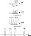
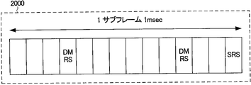
- FIG. 15A to 15C are diagrams illustrating an example of the SRS mechanism.
- 2000 represents a subframe on the time axis, and is a signal transmitted at one transmission opportunity of each mobile station.
- DMRS DeModulation Reference Signal
- DMRS DeModulation Reference Signal
- FIG. 15A DMRS (DeModulation Reference Signal) is a known demodulation reference signal for equalizing the propagation path distortion described in FIG. 14, and is arranged in the fourth and eleventh symbols of each subframe. Is done.
- a signal transmitted by the mobile station in order to estimate a rough propagation path characteristic of the entire system band for the purpose of performing scheduling for determining a frequency allocated to the user by the base station is an SRS. Examples of the SRS transmission method are 2001 shown in FIG. 15B and 2002 shown in FIG. 15C.
- SRS is transmitted in an arrangement called a distributed type in which the same Zadoff-Chu sequences as DMRS are arranged in a comb wave shape, and a plurality of bandwidths of SRS to be transmitted in one transmission are defined according to the transmission power of the mobile station and the like.
- FIG. 15B shows a case in which transmission can be performed over the entire band in one transmission opportunity. In this case, the propagation path can be grasped every 1 millisecond at the shortest.
- 2002 shown in FIG. 15C is an example of a case where SRS can be transmitted only in a part of the band.
- SRS can be transmitted only in a part of the band.
- first, to divide the band into four and transmit SRS as shown in the figure over four transmission opportunities (4 milliseconds), in order to grasp the propagation path characteristics of the entire system band Takes a long time.
- transmission of SRS also considers transmission of other mobile stations, there are transmission opportunities that are not transmitted, and even in this case, it may take 4 milliseconds or more.
- Clustered DFT-S-OFDM and DSC grasp the frequency response of the propagation path of the entire system band and send signals over a wide range.
- Good transmission characteristics can be obtained by selecting the frequency to be arranged and distributing the frequency. Therefore, if it takes a long time to grasp the propagation path characteristics of the entire system band, it will not be possible to follow the time fluctuation of the propagation path, and the propagation path will already greatly fluctuate when the determined allocation is reflected. There was a problem.
- the DMRS since the DMRS is not assigned to a frequency where no data signal is allocated, the DMRS alone cannot determine which frequency should be used in the entire system band at the next transmission opportunity. It was.
- the present invention has been made in view of such circumstances, and predicts the frequency response of a propagation path based on a known reference signal together with a data signal, and propagates the entire transmission band for performing frequency allocation in a short time. It is an object of the present invention to provide a wireless communication system, a receiving device, a transmitting device, a communication method of a wireless communication system, a control program, and an autonomous distributed network that can predict a road state.
- the radio communication system of the present invention receives a radio apparatus and a transmitter that transmits a radio signal in which a signal in which frequency domain signals are dispersedly arranged at a plurality of frequencies and a reference signal for propagation path estimation are multiplexed.
- a wireless communication system including a receiving device, wherein the receiving device predicts propagation path characteristics of an entire transmission band based on the distributed reference signals for propagation path estimation, and outputs the frequency domain signal.
- a plurality of frequencies to be distributed are determined, and information indicating the determined plurality of frequencies is transmitted to the transmission device.
- the propagation path characteristics of the entire transmission band are predicted based on the distributed reference signals for demodulation, and a plurality of frequencies for distributing the frequency domain signals are determined. It can be used to determine the allocated frequency in the entire system band. Thereby, the update time of allocation information can be shortened and the throughput can be improved.
- the propagation path estimation reference signal is a signal used to demodulate a data signal, and is arranged at the same frequency as the data signal. It is a feature.
- the receiving device includes a plurality of frequencies in which signals in the frequency domain are distributed and arranged with a highly reliable frequency in the predicted propagation path characteristics of the entire transmission band. It is characterized by selecting as a frequency.
- the receiving device calculates the reliability of the prediction based on a variance of noise that is a prediction error.
- This configuration makes it possible to easily and quickly quantify the reliability of prediction.
- the transmission device is characterized in that a search reference signal is arranged and transmitted at a frequency with low reliability of the prediction.
- This configuration makes it possible to more accurately grasp the propagation path characteristics of the entire system band while effectively using radio resources.
- the search reference signal is a sounding reference signal.
- the transmission device is characterized in that a data signal is arranged and transmitted at a frequency with low reliability of the prediction.
- the demodulation reference signal is arranged in a region with low prediction reliability, it is possible to grasp the frequency characteristics with higher accuracy even in a frequency region with low prediction reliability. This makes it easier to predict the propagation path characteristics of the entire system band and enables efficient transmission.
- the receiving apparatus of the present invention is a receiving apparatus that receives signals from a transmitting apparatus that performs radio transmission by distributing and arranging signals in a frequency domain in a plurality of frequencies, and for the demodulation arranged in the distributed arrangement.
- a propagation path characteristic prediction unit that predicts propagation path characteristics of the entire transmission band based on a reference signal
- an allocation frequency determination unit that determines a plurality of frequencies for distributing and arranging signals in the frequency domain, and the determined plurality of frequencies.
- a frequency allocation information generating unit that generates frequency allocation information to be transmitted, and transmitting the frequency allocation information to the transmission device.
- the propagation path characteristics of the entire transmission band are predicted based on the distributed reference signals for demodulation, and a plurality of frequencies for distributing the frequency domain signals are determined. It can be used to determine the allocated frequency in the entire system band. Thereby, the update time of allocation information can be shortened and the throughput can be improved.
- the reference signal for propagation path estimation is a signal used for demodulating a data signal, and is arranged at the same frequency as the data signal. It is said.
- the propagation path characteristic prediction unit includes a reliability calculation unit that calculates reliability of the propagation path characteristic of the entire predicted transmission band, and among the calculated reliability, And a frequency candidate determining unit that determines frequency candidates for distributing and arranging the signals in the frequency domain.
- the reliability calculation unit calculates the reliability of the prediction based on a variance of noise that is a prediction error.
- This configuration makes it possible to easily and quickly quantify the reliability of prediction.
- a transmitting apparatus is a transmitting apparatus that performs radio transmission to a receiving apparatus by distributing and arranging frequency domain signals in a plurality of frequencies, and the entire transmission band predicted by the receiving apparatus.
- a search reference signal is arranged and transmitted at a frequency with low prediction reliability.
- This configuration makes it possible to roughly grasp the propagation path characteristics of the entire system band while effectively using radio resources.
- the search reference signal is a sounding signal.
- the transmission device of the present invention is a transmission device that performs radio transmission to a reception device by distributing and arranging frequency domain signals in a plurality of frequencies, and the entire transmission band predicted by the reception device.
- a data signal is arranged and transmitted at a frequency with low reliability of prediction.
- the communication method of the wireless communication system of the present invention includes a transmitting device that performs wireless transmission by distributing and distributing frequency domain signals to a plurality of frequencies, and a receiving device that receives the wirelessly transmitted signal.
- a communication method for a wireless communication system wherein the receiving device predicts propagation path characteristics of an entire transmission band based on the distributed reference signal for propagation path estimation, and distributes the frequency domain signals in a distributed manner
- a plurality of frequencies to be transmitted, and information indicating the determined plurality of frequencies is transmitted to the transmitter, and the transmitter distributes frequency domain signals to a plurality of frequencies based on the information indicating the frequencies.
- Wireless transmission to the receiving device is a transmitting device that performs wireless transmission by distributing and distributing frequency domain signals to a plurality of frequencies, and a receiving device that receives the wirelessly transmitted signal.
- the propagation path characteristics of the entire transmission band are predicted based on the distributedly arranged reference signals for propagation path estimation, and a plurality of frequencies in which the frequency domain signals are distributed and determined are determined.
- the assigned frequency in the entire system band can be determined using the signal. Thereby, the update time of allocation information can be shortened and the throughput can be improved.
- a control program of the present invention is a control program for a receiving apparatus that receives a signal from a transmitting apparatus that performs radio transmission by distributing and arranging signals in a frequency domain at a plurality of frequencies. And processing for predicting propagation path characteristics of the entire transmission band based on the distributedly arranged reference signals for propagation path estimation, and an allocation frequency determination unit determines a plurality of frequencies for distributing and arranging the frequency domain signals.
- a series of processes that are read by a computer, a process of generating frequency allocation information indicating the determined plurality of frequencies, and a process of transmitting the frequency allocation information to the transmission device in a frequency allocation information generation unit It is characterized by being commanded to be executable and executable.
- the propagation path characteristics of the entire transmission band are predicted based on the distributedly arranged reference signals for propagation path estimation, and a plurality of frequencies in which the frequency domain signals are distributed and determined are determined.
- the assigned frequency in the entire system band can be determined using the signal. Thereby, the update time of allocation information can be shortened and the throughput can be improved.
- the autonomous decentralized network of the present invention is a plurality of communication devices that transmit and receive radio signals in which a signal in which frequency domain signals are distributed and arranged in a plurality of frequencies and a reference signal for propagation path estimation are multiplexed.
- An autonomous decentralized network configured, wherein any one of the communication devices predicts a propagation path characteristic of an entire transmission band based on the propagation path estimation reference signal, and distributes the frequency domain signal in a distributed manner A plurality of frequencies to be determined is determined, and information indicating the determined plurality of frequencies is transmitted to any other transmitting device.
- the propagation path characteristics of the entire transmission band are predicted based on the distributed reference signals for demodulation, and a plurality of frequencies for distributing the frequency domain signals are determined. It can be used to determine the allocated frequency in the entire system band. Thereby, the update time of allocation information can be shortened and the throughput can be improved.
- FIG. 1 is a diagram illustrating an example of an autonomous distributed network.
- the RB size is the cluster size and the number of RBs in the system band is 12 unless otherwise specified.
- the cluster size need not be the same as the RB size, and is essentially the same even if the cluster size is not the same as the RB size.
- the present invention is not limited to Clustered DFT-S-OFDM, but for example, transmission capable of distributing and distributing frequency signals over the entire system band such as OFDM, which is a multicarrier system, and MC-CDM (Multi-Carrier Code Division Multiplexing). Since the present invention can be applied to methods, the same concept using these methods is also included in the present invention.
- the following embodiments are intended for uplink communication, even if the same technique is used for the downlink, it is essentially the same as the present invention.
- the meaning of predicting the propagation path is not limited to the distributed arrangement, but can be used for the allocation of the transmission system of the continuous arrangement such as SC-FDMA.
- description is made on the assumption that prediction is performed using a reference signal for demodulating a data signal.
- this concept is also applied to the present invention. include.
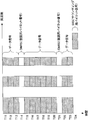
- FIG. 1 is a diagram illustrating an example of the concept of an embodiment of the present invention.
- RB1 to RB12 indicate RBs in the system band (assignable band), and L1 indicates the channel characteristic of the uplink frequency.
- C1 to C8 are clustered frequency signals, which are arranged at good frequencies in the system band.
- DMRS reference signal
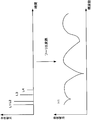
- FIG. 2 is a diagram showing the relationship between the impulse response and the frequency response described above.
- the impulse response of the radio propagation path is determined by the number of impulse response paths (channel memory) measured by the receiving apparatus and the delay time.
- the propagation path gain H1 of the frequency axis is determined by the power and delay time of the paths L1 to L4 in this case. The smaller the delay dispersion, the stronger the constraint between adjacent discrete frequencies.
- the frequency response of the assigned surroundings can be predicted to some extent by using this.
- the frequency response partially estimated by the distributed DMRS is converted into an impulse response by IFFT, leaving only the impulse response of the length of CP from the beginning, Insert zeros in the rest.
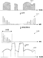
- FIG. 3 is a diagram illustrating an example of a concept for predicting a frequency response.
- H11 is a frequency characteristic estimated from the assigned frequency, and the frequency that is not assigned is zero.
- L11 is obtained by converting this on the time axis, and the frequency that has not been transmitted at this point is treated as having a gain of zero, so that the impulse response is equivalently extended.
- L12 is inserted as indicated by L12 for the impulse response appearing after the CP.
- the length of the CP length is used as a reference as an actual process to be actually performed, but it is not necessarily the CP length. If the maximum delay time of the delayed wave is measured, it is set to that value.
- the present invention is not limited to this.
- L12 is converted into a frequency response by FFT like H12.
- FFT frequency response
- frequencies that are not used for transmission are complemented, but the accuracy of the channel gain of the frequencies not assigned at this time is evaluated by the true frequency characteristics and the magnitude of the error variance of H12.
- how to calculate the variance of noise will be described below.
- R is a complex received signal vector of N FFT ⁇ 1 on the frequency axis
- H is a complex channel gain of the entire band
- a matrix, Sp is an N DFT ⁇ 1 transmission signal vector representing the amplitude and phase of the pilot signal on the frequency axis.
- R, H, and Sp are each represented by the following equation.
- ⁇ is a complex noise vector of N FFT ⁇ 1
- M is an N FFT ⁇ N DFT mapping matrix indicating to which frequency each discrete spectrum (subcarrier) is assigned
- the column vector index is an index before arrangement
- the row vector index represents the post-arrangement index, and is a matrix in which only the assigned element is 1 and the remaining elements are 0.
- the received signal is represented by Expression (6).
- the frequency response is obtained by dividing from the received signal by the signal point arrangement of the transmitted DMRS.
- the signal point arrangement of pilot signals of each frequency is all set to 1 (denoted as INDFT ⁇ 1 ).
- Equation (6) Equation (6)
- A ⁇ N FFT M T FW.
- F is a DFT matrix of N DFT points to be transformed to the frequency domain by multiplication
- h is a complex impulse response vector of L ⁇ 1
- L is the number of paths (number of points of CP), )
- W is a matrix for transforming the impulse response of the N FFT points is equivalent to the process of placing a zero from L + 1 point in the impulse response to N FFT points, represented by the formula (10).
- Equation (11) the estimated impulse response value is expressed by Equation (11). This process is equivalent to the process of calculating L11 in FIG.
- the first term represents a true impulse response
- the second term represents a noise component
- a + is a pseudo inverse matrix of the matrix A
- a + (AA H ) ⁇ 1 A H.
- Equation (12) an estimated value of the actual frequency response is calculated as indicated by H12 in FIG.
- H12 the variance of the second term of equation (12) is considered.
- the covariance matrix of the second term of Expression (12) is expressed by the following Expression (13).
- N 0 is the noise spectrum power density which is the noise power in the receiver per unit frequency.
- This diagonal component means the magnitude of the noise power at each frequency. The smaller the component, the higher the reliability, and the larger the component, the lower the reliability.
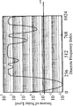
- FIG. 4 is a diagram illustrating an example of noise power at each frequency calculated by Expression (13).
- the horizontal axis is the frequency index, and the vertical axis is the reciprocal of the diagonal component represented by Equation (13).
- SNR signal to noise power ratio
- a threshold value L21 is set for this value, and a frequency equal to or higher than the threshold value is determined to be highly reliable and can be selected as an assignable frequency. Although this threshold value has a small number of assignable frequency candidates, a low-reliability frequency can be selected.
- this threshold value is large, only reliable ones can be selected, so the number of selectable frequencies is reduced and the number of subcarriers to be selected is reduced.
- This threshold value may be optimized by a simulation using a computer, or may be set in advance to a fixed value that is easy to handle.
- FIG. 5 is a diagram showing a characteristic when L31 can completely grasp the frequency characteristic of the propagation path of the entire band, a characteristic when L32 is a characteristic of this embodiment, and a characteristic when L33 is not selected. Further, the horizontal axis represents the threshold value described in FIG. 4, and the vertical axis represents the average gain of the selected frequency. From the figure, not only SRS by using this method, also confirmed to be selectable from DMRS, in particular, it can be confirmed that the threshold 10 -1 can select a good frequency with high probability. Thus, it can be seen that this method is effective.
- FIG. 6 is a diagram illustrating a configuration of the receiving device.
- the receiving apparatus includes a receiving antenna 41, a radio unit 42, an A / D (Analog-to-Digital) converting unit 43, a CP removing unit 44, a reference signal separating unit 45, a propagation path characteristic / noise variance estimating unit 46, an S / P (Serial to Parallel) conversion unit 47, FFT unit 48, spectrum demapping unit 49, equalization unit 50, IDFT unit 51, P / S (Parallel to Serial) conversion unit 52, demodulation unit 53, deinterleave unit 54, decoding unit 55 , A propagation path characteristic demapping unit 56, a propagation path characteristic prediction unit 57, an allocation frequency determination unit 58, and a frequency allocation information generation unit 59.
- a propagation path characteristic demapping unit 56 a propagation path characteristic prediction unit 57
- an allocation frequency determination unit 58 and a frequency allocation information generation unit 59.
- the reception signals received by the reception antenna 41 and the radio unit 42 are converted into digital signals by the A / D conversion unit 43, the CP is removed by the CP removal unit 44, and the DMRS is separated by the reference signal separation unit 45.
- the propagation path characteristics and the noise power of thermal noise necessary for detecting data from the propagation path characteristics / noise variance estimation section 46 by the equalization section 50 are estimated from the DMRS.
- the propagation path characteristic / noise variance estimation unit 46 has a time / frequency conversion function.
- the propagation path characteristic demapping unit 56 extracts the propagation path characteristic only from the frequency used based on the assigned frequency information.
- the data signal from which the DMRS has been separated is parallelized by the S / P converter 47 and converted into a frequency signal by the FFT unit 48.
- the converted frequency signal is extracted from the allocated frequency information by the spectrum demapping unit 49, and the equalization unit 50 equalizes the distortion of the channel from the frequency response input from the channel characteristic demapping unit 56, and the IDFT unit 51.
- To convert to a time signal The converted time signal is serialized by the P / S converter 52 and decomposed from the modulation symbol into bits by the demodulator 53. Thereafter, the deinterleaving unit 54 returns the bits to the original time order, and the decoding unit 55 performs error correction processing to obtain a decoded bit string.
- the received DMRS used for demodulation is calculated by the propagation path characteristic predicting unit 57 by calculating the predicted value of the propagation path characteristic of the entire transmission band and the reliability of the unassigned frequency, and selecting the frequency from the reliability.
- Allocation information is determined, and the allocation frequency of the next transmission opportunity is determined using the frequency characteristic estimated from the DMRS by the allocation frequency determination unit 58 and the predicted value estimated by the channel characteristic prediction unit 57.
- the finally determined allocation frequency information is converted into a signal format for feedback to the transmission apparatus in the frequency allocation information generation unit 59 and notified to the transmission apparatus.
- FIG. 7 is a diagram illustrating a configuration example of the propagation path characteristic prediction unit 57.
- the propagation path characteristic prediction unit 57 includes a reliability calculation unit 61 and a frequency candidate determination unit 62.
- the frequency response estimated from the DMRS is an error between the predicted value and the true value at each frequency by the reliability calculation unit 61 using Equation (13) in order to calculate the reliability of the channel to which no data is assigned.
- the power of (emphasized noise) is calculated and input to the frequency candidate determination unit 62.
- the frequency candidate determination unit 62 determines a frequency having reliability exceeding the threshold as a selectable frequency candidate by the determination based on the threshold.
- FIG. 8 is a flowchart showing an operation of selecting a frequency with high reliability of prediction of propagation path characteristics.
- step S1 a matrix A that is a gain when a product obtained by multiplying the impulse response represented by the equation (7) by the matrix A from the left is a received signal is calculated.
- step S2 an inverse matrix (pseudo inverse matrix) A + of the matrix A is calculated.
- step S3 the predicted value of the propagation path characteristics of the entire band is calculated from equation (11) using A + obtained, and the covariance matrix obtained in equation (13) is calculated in step S4. Compute the reciprocal of the diagonal component at.
- a threshold is set based on the magnitude of the noise component of each frequency obtained in step S6, a highly reliable frequency is determined as a selectable frequency in step S7, and the predicted value is set as a propagation path characteristic. To do.
- the allocation frequency in the entire system band can be determined using the DMRS for data demodulation, the update time of the allocation information can be shortened and the throughput can be improved.
- a search pilot is transmitted to a frequency with extremely low reliability. As shown in FIG. 4, although the reliability around the frequencies 0 to 256 is remarkably low, there is still a possibility that the channel gain is high at a frequency with low reliability. Therefore, it is conceivable that the search pilot is transmitted only to frequencies around the frequencies 0 to 256.
- FIG. 9A and 9B are diagrams illustrating an example of the concept of the present embodiment.
- FIG. 9A shows an example of arrangement of reference signals
- FIG. 9B shows an example of arrangement of reference signals for search.
- the frequency response is less reliable as it is farther from the assigned frequency. Therefore, the reliability is grasped in the first stage, and the search reference signal is transmitted to a frequency with low reliability as shown in FIG. 9B. Thereby, it is possible to grasp the propagation path characteristics of the entire system band with higher accuracy than the first embodiment while effectively using radio resources.
- FIG. 10 is a diagram illustrating an example of a mobile station apparatus.
- the mobile station apparatus includes an encoding unit 101, an interleaving unit 102, a modulating unit 103, a DFT unit 104, a reference signal generating unit 105, a reference signal multiplexing unit 106, a spectrum dividing unit 107, a frequency allocation information detecting unit 108, a spectrum arranging unit 109, It includes an IFFT unit 110, a CP insertion unit 111, a radio unit 112, a transmission antenna 113, a search reference signal generation unit 114, and a search reference signal allocation unit 115. Since the encoding unit 101 to the transmission antenna 113 have the same functions as those in FIG.
- the search reference signal generation unit 114 generates a search reference signal, and the frequency that is considered to have low reliability based on the data allocation information obtained by the frequency allocation information detection unit 108 in the search reference signal allocation unit 115 A search reference signal is assigned to.
- the search reference signal allocation unit 115 uses information such as a frequency that is determined to be low in reliability and cannot be allocated to a continuous frequency that is somewhat wide. For example, various methods such as allocating to frequencies where data is not continuously arranged for X subcarriers or more are conceivable. The arrangement based on the reliability is the same as the present invention. It is also conceivable to provide a threshold for the reliability calculated as in the first embodiment, and notify and transmit a reliability frequency equal to or lower than a certain threshold. Since these are also essentially the same, they are included in the present invention.
- FIG. 11 is a diagram illustrating an example of this embodiment.
- an LTE uplink is described as an example, but the present invention is not limited to this.
- the vertical axis represents time
- the horizontal axis represents frequency
- T11 to T24 each represent a unit of DFT, that is, a DFT block.
- T14 and T21 are pilot signals for demodulating the data signal in which DMRS is arranged.
- an SRS which is a sounding pilot signal, is arranged at T24.
- the SRS is used to grasp the channel characteristics of the entire system band, and the SRS is arranged in a distributed type.
- the propagation path around the frequency transmitted by DMRS is predicted, and for the frequency that is not widely transmitted, the propagation path characteristic of the frequency having low reliability is grasped by transmitting SRS to the band. . If such a method is used, the current system can efficiently grasp the frequency characteristics of the entire system band, and communication utilizing the features of Clustered DFT-S-OFDM becomes possible.
- the present embodiment has been described with reference to an application example in LTE, the same can be achieved in a system in which transmission of sounding pilot signals, demodulation pilots, and data signals are both performed in a distributed manner. Are included in the present invention.
- FIG. 12A and 12B are diagrams illustrating an example of the present embodiment.
- FIG. 12A when data is arranged only in accordance with the reception status, when data is assigned to a close frequency such as R10, it can be said that the prediction accuracy is high because the accuracy of prediction is high. In such a band where data is not widely allocated, the reliability is low. For this reason, not all of the allocated data signals are arranged at frequencies having good propagation path characteristics, but a part of the data signals is allocated to an area where reliability is low, as shown in FIG. 12B.
- the pilot signal for demodulation is appropriately arranged in the region of R11, so that it is possible to grasp a good frequency in the region of R11, and it is assumed that it is not arranged only with a certain transmission opportunity.
- the optimum arrangement can be performed at other transmission opportunities. Therefore, it becomes easy to predict the propagation path characteristics of the entire system band, and transmission can be performed efficiently.
- This method may be performed adaptively at the next transmission opportunity when a region with low reliability occurs, or a resource block (RB) having the lowest received SNR is selected for an optimal arrangement that can be grasped at present.
- a method of assigning may be used.
- data arrangement that is arranged evenly every four subframes may be used.
- control program of the present invention is a control program for a receiving device that receives a signal from a transmitting device that performs radio transmission by distributing and arranging signals in a frequency domain in a plurality of frequencies.
- a series of processes including a process of generating frequency allocation information indicating the determined plurality of frequencies and a process of transmitting the frequency allocation information to the transmission device can be read and executed by a computer. It is characterized by being commanded.
- the propagation path characteristics of the entire transmission band are predicted based on the distributed reference signals for demodulation, and a plurality of frequencies for distributing and distributing frequency domain signals are determined. It can be used to determine the allocated frequency in the entire system band. Thereby, the update time of allocation information can be shortened and the throughput can be improved.
- this embodiment is an application example to an autonomous distributed wireless network.
- frequency allocation is performed by receiving sounding signals at the base station apparatuses. Can be determined.
- there is no centralized management communication device such as a base station device, and therefore a sounding reference signal cannot be transmitted.
- the throughput can be improved by using the prediction technique and the search reference signal, which are the essence of the present invention.
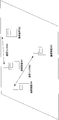
- FIG. 16 is a diagram illustrating an example of an autonomous distributed network.
- This figure shows an indoor network such as an office, and mobile stations in a cellular system establish communication with each other by establishing a radio link.
- a wireless link 301 for communication between the communication device 201 and the communication device 202 and a wireless link 302 for communication between the communication device 203 and the communication device 204 are established.
- a sounding reference signal such as SRS over the entire transmission band
- SRS transmission covers the entire band, interference occurs when transmitted simultaneously.
- it is impossible to control the time for transmitting the SRS so that the wireless link 301 and the wireless link 302 do not transmit the SRS at the same time.
- it can be predicted by using the prediction method of the present invention.
- the prediction method itself is the same as the estimation method using DMRS described in the first to fourth embodiments, the description thereof is omitted. Furthermore, if the above estimation method alone does not provide much accuracy, the search reference signal is transmitted to a good frequency to which it is assigned, and the accuracy is increased. According to the present embodiment, accuracy is improved by using the present invention even in an autonomous distributed network.
- reception antenna 42 radio unit 43 A / D conversion unit 44 CP removal unit 45 reference signal separation unit 46 propagation path characteristic / noise variance estimation unit 47 S / P conversion unit 48 FFT unit 49 spectrum demapping unit 50 equalization unit 51 IDFT Unit 52 P / S conversion unit 53 demodulation unit 54 deinterleaving unit 55 decoding unit 56 channel characteristic demapping unit 57 channel characteristic prediction unit 58 allocation frequency determination unit 59 frequency allocation information generation unit 61 reliability calculation unit 62 frequency candidate determination Unit 101 Coding unit 102 Interleaving unit 103 Modulating unit 104 DFT unit 105 Reference signal generating unit 106 Reference signal multiplexing unit 107 Spectrum dividing unit 108 Frequency allocation information detecting unit 109 Spectrum arranging unit 110 IFFT unit 111 CP inserting unit 112 Radio unit 113 Transmitting antenna 114 Search reference signal generator 115 Search reference Signal allocation section 1001 Encoding section 1002 Interleaving section 1003 Modulation section 1004 DFT section 1005 Reference signal generation section 1006 Reference signal multiplexing section 1007 Spectrum division section 100
Landscapes
- Engineering & Computer Science (AREA)
- Signal Processing (AREA)
- Computer Networks & Wireless Communication (AREA)
- Power Engineering (AREA)
- Mobile Radio Communication Systems (AREA)
Abstract
データ信号と共に既知の参照信号に基づいて伝搬路の周波数応答を予測し、短い時間で周波数割当を行なうための伝送帯域全体の伝搬路の状態を予測する。周波数領域の信号を複数の周波数に分散配置して無線送信を行なう送信装置から信号を受信する受信装置であって、前記分散配置された伝搬路推定用の参照信号に基づいて伝送帯域全体の伝搬路特性を予測する伝搬路特性予測部57と、前記周波数領域の信号を分散配置する複数の周波数を決定する割当周波数決定部58と、前記決定した複数の周波数を示す周波数割当情報を生成する周波数割当情報生成部59と、を備え、前記周波数割当情報を前記送信装置へ送信する。
Description
本発明は、周波数領域の信号を複数の周波数に分散配置して無線送信を行なう技術に関する。
近時、第3.9世代の携帯電話の無線通信システムであるLTE(Long Term Evolution)システムの標準化がほぼ完了し、最近ではLTEシステムをより発展させた第4世代の無線通信システムであるLTE-A(LTE-Advanced、IMT-Aの1つとして呼称される。)の標準化が開始された。LTE-Aシステムは、LTEシステムの端末が接続できなければならないという要求条件があるため、LTEシステムの後方互換性(Backward Compatibility)を維持しなければならないとされている。
ところで、上り回線(移動局から基地局への通信)の伝送方式として、DFT-S-OFDM(Discrete Fourier Transform Spread Orthogonal Frequency Division Multiplexing)と呼ばれる伝送方式がLTEで既に採用されている。この伝送方式は、多元接続方式として定義するとSC-FDMA(Single Carrier Frequency Division Multiple Access)とも呼称される。LTE-Aにおいても、後方互換性の観点からDFT-S-OFDMを上り回線でサポートすることは既に決まっており、LTE-Aの上り回線ではさらなる周波数利用効率の改善を目指し、Clustered DFT-S-OFDM(ダイナミックスペクトル制御、DSC:Dynamic Spectrum Control)と呼ばれる技術が提案されている(例えば、非特許文献1参照)。
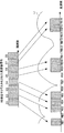
図13は、Clustered DFT-S-OFDMの概念の一例を示す図である。ここでは、ブロック内に含まれるシンボル数を8、クラスタサイズ(1クラスタに含まれる離散スペクトル数、すなわちサブキャリア数)を2として説明する。まず、時間軸の変調シンボルT1~T8は、8点のDFTにより周波数信号S1~S8に変換される。次に、得られた周波数信号S1~S8は2サブキャリア毎にクラスタ化され、各クラスタC101~C104は、システム帯域全体における帯域の空き状態に応じて周波数の任意の位置に配置される。
なお、ここでは説明を簡単にするためにクラスタサイズ(クラスタに含まれるサブキャリア数)を2としたが、LTEでは各移動局が伝送に用いる周波数軸の無線資源の最小単位として、リソースブロック(RB:Resource Block)と呼ばれる12の連続するサブキャリアと既に決定されているため、Clustered DFT-S-OFDMは、実際には12サブキャリアの自然数倍のクラスタサイズで運用される。
ここで、LTEで用いられているDFT-S-OFDMはこのS1~S8をクラスタ分割せず複数のRBを連続的に使用する伝送方法である。なお、以下ではクラスタサイズをRBのサイズで説明を行なう。
図14は、移動局におけるClustered DFT-S-OFDMの送信装置の一例を示す図である。この送信装置は、符号部1001、インターリーブ部1002、変調部1003、DFT部1004、参照信号生成部1005、参照信号多重部1006、スペクトル分割部1007、周波数割当情報検出部1008、スペクトル配置部1009、IFFT(Inverse Fast Fourier Transform)部1010、CP(Cyclic Prefix)挿入部1011、無線部1012、送信アンテナ1013から構成される。
情報ビット列は、符号部1001により誤り訂正符号化により符号ビットが得られ、インターリーブ部1002により符号ビットの時間順が並び替えられる。時間順が並び替えられた符号ビットは、変調部1003により符号ビットが0であるか1であるかに応じて位相や振幅に符号ビットがマッピングされ、変調シンボルが生成される。生成された変調シンボルはDFT部1004により周波数信号が得られる。
一方、受信装置で伝搬路による歪みを等化するために送信する既知の参照信号(パイロット信号とも呼称する。)が参照信号生成部1005により生成され、参照信号多重部1006において、DFT部1004より出力された周波数信号と多重される。ここで、参照信号に関しては、例えばLTEにおいて参照信号を構成する周波数信号として、CAZAC(Constant Amplitude and Zero Auto-Correlation)系列の1つであるZadoff-Chu系列に基づく系列が選択される。多重された信号は、スペクトル分割部1007により所定のクラスタサイズに分割され、スペクトル配置部1009により、周波数割当情報検出部1008から通知された周波数割当情報に基づいて所定の周波数に配置される。
ここで、周波数割当情報検出部1008では、下り回線で送信される制御信号(例えば、LTEではPDCCH(Physical Downlink Control Channel))を移動局が予め受信しており、通常はそのクラスタ配置に関する情報を用いて配置する。次に、配置された周波数信号はIFFT部1010によりシステム帯域全体のサブキャリア数(もしくはシステムで規定されたポイント数)をポイント数とするIFFTにより時間信号に変換され、CP挿入部1011により無線伝搬路の最大遅延時間に応じてシステムで決定された長さのCP(波形の末尾のCP長分のコピー)を挿入され、無線部1012により無線周波数にアップコンバートされ、送信アンテナ1013から送信される。
次に、周波数割当情報を設定するメカニズムについて説明する。上述したように、周波数軸で無線リソースを割り当てるスケジューリングをする場合には、伝送帯域全体における各移動局と基地局の間の伝搬路特性を把握するために、既知のサウンディング用の参照信号が送信される。例えば、LTEでは、SRS(Sounding Reference Signal)が最短でサブフレームと呼ばれる伝送機会毎に送信され、その送信周期は最短で1ミリ秒である。
図15A~図15Cは、SRSのメカニズムの一例を示す図である。図15Aにおいて、2000は時間軸のサブフレームを表しており、各移動局の1回の伝送機会で送信される信号である。図15Aにおいて、DMRS(DeModulation Reference Signal)は、図14で述べた伝搬路の歪みを等化するための既知の復調用の参照信号であり、各サブフレームの4番目と11番目のシンボルに配置される。また、基地局がユーザに割り当てる周波数を決定するスケジューリングを行なう目的でシステム帯域全体の大まかな伝搬路特性を推定するために移動局が送信する信号がSRSである。このSRSの送信方法を示した例が図15Bに示した2001、図15Cに示した2002である。SRSは、DMRSと同じZadoff-Chu系列を櫛の波状に並べるDistributed型と呼ばれる配置で送信され、移動局の送信電力などに応じて1回の伝送で送信するSRSの帯域幅が複数規定されている。図15Bに示した2001が、1回の伝送機会で全帯域にわたって送信できる場合である。この場合、最短の1ミリ秒毎に伝搬路を把握することができる。
一方、図15Cに示した2002が帯域の一部しかSRSを送信できない場合の一例である。図15Cに示すように、まず、帯域を4分割し、4回の伝送機会(4ミリ秒)かけてSRSを同図のように送信するため、システム帯域全体の伝搬路特性を把握するためには長い時間がかかる。さらに、SRSの送信は他の移動局の送信も考慮するので、送信されない伝送機会もあるので、この場合でも4ミリ秒以上かかることもある。
3GPP TS36.211 v8.5.0
しかしながら、Clustered DFT-S-OFDMやDSC(サブキャリアの分散配置が可能なOFDMなどのマルチキャリア伝送も含む)などは、システム帯域全体の伝搬路の周波数応答を把握した上で、広範囲にわたって信号を配置する周波数を選択し、分散配置することで良好な伝送特性が得られる。そのため、システム帯域全体の伝搬路特性を把握するのに長い時間かかってしまうと、伝搬路の時変動に追随できず、決定した割当が反映されるころには伝搬路が既に大きく変動してしまうという問題があった。
さらに、DMRSはデータ信号を配置していない周波数に割り当てられないため、DMRSだけでは、次の伝送機会において、システム帯域全体でどの周波数を用いるのがよいかを決定することができないという問題があった。
本発明は、このような事情に鑑みてなされたものであり、データ信号と共に既知の参照信号に基づいて伝搬路の周波数応答を予測し、短い時間で周波数割当を行なうための伝送帯域全体の伝搬路の状態を予測することができる無線通信システム、受信装置、送信装置、無線通信システムの通信方法、制御プログラムおよび自律分散型ネットワークを提供することを目的とする。
(1)上記の目的を達成するために、本発明は、以下のような手段を講じた。すなわち、本発明の無線通信システムは、周波数領域の信号を複数の周波数に分散配置した信号と、伝搬路推定用の参照信号とを多重した無線信号を送信する送信装置および前記無線信号を受信する受信装置で構成される無線通信システムであって、前記受信装置は、前記分散配置された伝搬路推定用の参照信号に基づいて伝送帯域全体の伝搬路特性を予測し、前記周波数領域の信号を分散配置する複数の周波数を決定し、決定した複数の周波数を示す情報を前記送信装置へ送信することを特徴としている。
このように、分散配置された復調用の参照信号に基づいて伝送帯域全体の伝搬路特性を予測し、周波数領域の信号を分散配置する複数の周波数を決定するので、データ復調用の参照信号を用いてシステム帯域全体における割当周波数を決定することができる。これにより、割当情報の更新時間を短くすることができ、スループットの向上を図ることができる。
(2)また、本発明の無線通信システムにおいて、前記伝搬路推定用の参照信号は、データ信号を復調するために用いられる信号であって、前記データ信号と同一の周波数に配置されることを特徴としている。
この構成により、データ復調用の参照信号を用いてシステム帯域全体における割当周波数を決定することができる。これにより、割当情報の更新時間を短くすることができ、スループットの向上を図ることができる。
(3)また、本発明の無線通信システムにおいて、前記受信装置は、予測した伝送帯域全体の伝搬路特性のうち、予測の信頼性の高い周波数を、前記周波数領域の信号を分散配置する複数の周波数として選択することを特徴としている。
この構成により、信頼性の高い周波数のみを用いて、システム帯域全体における割当周波数を決定することができる。これにより、割当情報の更新時間を短くすることができ、スループットの向上を図ることができる。
(4)また、本発明の無線通信システムにおいて、前記受信装置は、予測の誤差である雑音の分散に基づいて、前記予測の信頼性を算出することを特徴としている。
この構成により、予測の信頼性を簡易且つ迅速に数値化することが可能となる。
(5)また、本発明の無線通信システムにおいて、前記送信装置は、前記予測の信頼性の低い周波数に探索用参照信号を配置して送信することを特徴としている。
この構成により、無線リソースを効果的に利用しつつ、システム帯域全体の伝搬路特性をより高精度に把握することが可能となる。
(6)また、本発明の無線通信システムにおいて、前記探索用参照信号は、サウンディング用の参照信号であることを特徴としている。
この構成により、受信装置において、全帯域を把握するまでの時間を短くすることができ、良好な周波数を効率的に把握することができる。
(7)また、本発明の無線通信システムにおいて、前記送信装置は、前記予測の信頼性の低い周波数にデータ信号を配置して送信することを特徴としている。
この構成により、予測の信頼性の低い領域に復調用の参照信号が配置されるため、予測の信頼性の低い周波数領域でもより高精度に周波数特性を把握することが可能となる。これにより、システム帯域全体の伝搬路特性を予測しやすくなり、効率的な伝送が可能となる。
(8)また、本発明の受信装置は、周波数領域の信号を複数の周波数に分散配置して無線送信を行なう送信装置から信号を受信する受信装置であって、前記分散配置された復調用の参照信号に基づいて伝送帯域全体の伝搬路特性を予測する伝搬路特性予測部と、前記周波数領域の信号を分散配置する複数の周波数を決定する割当周波数決定部と、前記決定した複数の周波数を示す周波数割当情報を生成する周波数割当情報生成部と、を備え、前記周波数割当情報を前記送信装置へ送信することを特徴としている。
このように、分散配置された復調用の参照信号に基づいて伝送帯域全体の伝搬路特性を予測し、周波数領域の信号を分散配置する複数の周波数を決定するので、データ復調用の参照信号を用いてシステム帯域全体における割当周波数を決定することができる。これにより、割当情報の更新時間を短くすることができ、スループットの向上を図ることができる。
(9)また、本発明の受信装置において、前記伝搬路推定用の参照信号は、データ信号を復調するために用いられる信号であって、前記データ信号と同一の周波数に配置されることを特徴としている。
この構成により、データ復調用の参照信号を用いてシステム帯域全体における割当周波数を決定することができる。これにより、割当情報の更新時間を短くすることができ、スループットの向上を図ることができる。
(10)また、本発明の受信装置において、前記伝搬路特性予測部は、予測した伝送帯域全体の伝搬路特性の信頼性を算出する信頼性算出部と、前記算出された信頼性のうち、前記周波数領域の信号を分散配置する周波数の候補を決定する周波数候補決定部と、を備えることを特徴としている。
この構成により、信頼性の高い周波数のみを用いて、システム帯域全体における割当周波数を決定することができる。これにより、割当情報の更新時間を短くすることができ、スループットの向上を図ることができる。
(11)また、本発明の受信装置において、前記信頼性算出部は、予測の誤差である雑音の分散に基づいて、前記予測の信頼性を算出することを特徴としている。
この構成により、予測の信頼性を簡易且つ迅速に数値化することが可能となる。
(12)また、本発明の送信装置は、周波数領域の信号を複数の周波数に分散配置して受信装置に対して無線送信を行なう送信装置であって、前記受信装置が予測した伝送帯域全体の伝搬路特性のうち、予測の信頼性の低い周波数に探索用参照信号を配置して送信することを特徴としている。
この構成により、無線リソースを効果的に利用しつつ、システム帯域全体の伝搬路特性を大まかに把握することが可能となる。
(13)また、本発明の送信装置において、前記探索用参照信号は、サウンディング用の信号であることを特徴としている。
この構成により、受信装置において、全帯域を把握するまでの時間を短くすることができ、良好な周波数を効率的に把握することができる。
(14)また、本発明の送信装置は、周波数領域の信号を複数の周波数に分散配置して受信装置に対して無線送信を行なう送信装置であって、前記受信装置が予測した伝送帯域全体の伝搬路特性のうち、予測の信頼性の低い周波数にデータ信号を配置して送信することを特徴としている。
この構成により、予測の信頼性の低い領域に復調用の参照信号が配置されるため、予測の信頼性の低い周波数領域でも良好な周波数を把握することが可能となる。これにより、システム帯域全体の伝搬路特性を予測しやすくなり、効率的な伝送が可能となる。
(15)また、本発明の無線通信システムの通信方法は、周波数領域の信号を複数の周波数に分散配置して無線送信を行なう送信装置および前記無線送信された信号を受信する受信装置で構成される無線通信システムの通信方法であって、前記受信装置が、前記分散配置された伝搬路推定用の参照信号に基づいて伝送帯域全体の伝搬路特性を予測し、前記周波数領域の信号を分散配置する複数の周波数を決定し、決定した複数の周波数を示す情報を前記送信装置へ送信し、前記送信装置が、前記周波数を示す情報に基づいて、周波数領域の信号を複数の周波数に分散配置して前記受信装置に対して無線送信を行なうことを特徴としている。
このように、分散配置された伝搬路推定用の参照信号に基づいて伝送帯域全体の伝搬路特性を予測し、周波数領域の信号を分散配置する複数の周波数を決定するので、データ復調用の参照信号を用いてシステム帯域全体における割当周波数を決定することができる。これにより、割当情報の更新時間を短くすることができ、スループットの向上を図ることができる。
(16)また、本発明の制御プログラムは、周波数領域の信号を複数の周波数に分散配置して無線送信を行なう送信装置から信号を受信する受信装置の制御プログラムであって、伝搬路特性予測部において、前記分散配置された伝搬路推定用の参照信号に基づいて伝送帯域全体の伝搬路特性を予測する処理と、割当周波数決定部において、前記周波数領域の信号を分散配置する複数の周波数を決定する処理と、周波数割当情報生成部において、前記決定した複数の周波数を示す周波数割当情報を生成する処理と、前記周波数割当情報を前記送信装置へ送信する処理と、の一連の処理がコンピュータに読み取り可能および実行可能にコマンド化されたことを特徴としている。
このように、分散配置された伝搬路推定用の参照信号に基づいて伝送帯域全体の伝搬路特性を予測し、周波数領域の信号を分散配置する複数の周波数を決定するので、データ復調用の参照信号を用いてシステム帯域全体における割当周波数を決定することができる。これにより、割当情報の更新時間を短くすることができ、スループットの向上を図ることができる。
(17)また、本発明の自律分散型ネットワークは、周波数領域の信号を複数の周波数に分散配置した信号と、伝搬路推定用の参照信号とを多重した無線信号を送受信する複数の通信装置で構成される自律分散型ネットワークであって、いずれか一つの前記通信装置は、前記伝搬路推定用の参照信号に基づいて伝送帯域全体の伝搬路特性を予測し、前記周波数領域の信号を分散配置する複数の周波数を決定し、決定した複数の周波数を示す情報をいずれか他の前記送信装置へ送信することを特徴としている。
このように、分散配置された復調用の参照信号に基づいて伝送帯域全体の伝搬路特性を予測し、周波数領域の信号を分散配置する複数の周波数を決定するので、データ復調用の参照信号を用いてシステム帯域全体における割当周波数を決定することができる。これにより、割当情報の更新時間を短くすることができ、スループットの向上を図ることができる。
本発明によれば、伝搬路応答の良好な周波数特性を把握することができるため、高い周波数選択ダイバーシチ効果が得られ、伝送特性またはスループットが向上する。
以下、本発明の実施形態について図面を参照して説明する。以下の実施形態では、特に断りがない限りRBサイズをクラスタサイズとし、システム帯域のRB数が12であるものとして説明を行なう。しかし、クラスタサイズがRBサイズと同一である必要はなく、クラスタサイズがRBサイズと同一でなくても本質的に同一である。また、本発明はClustered DFT-S-OFDMだけでなく、例えば、マルチキャリア方式であるOFDM方式やMC-CDM(Multi-Carrier Code Division Multiplexing)などのシステム帯域全体に周波数信号を分散配置可能な伝送方式にも適用できるため、これらの方式を用いた同一の概念も本発明に含まれる。さらに、以下の実施形態では上り回線の通信を対象としているが、同一の手法を下り回線に用いても本発明と本質的に同一である。また、伝搬路を予測するという意味では分散配置に限定されるものではなく、SC-FDMAのような連続配置の伝送方式の割当にも使用可能である。さらに、以下の実施形態では、データ信号の復調用の参照信号で予測することを前提に説明するが、一部しか送信されないサウンディング用の参照信号から予測することもできるため、この概念も本発明に含まれる。
[第1の実施形態]
図1は、本発明の実施形態の概念の一例を示す図である。ここでは、また、RB1~RB12はシステム帯域(割当可能な帯域)内の各RBを示しており、L1は上り回線の周波数の伝搬路特性を示している。また、C1~C8はクラスタ化された周波数信号であり、これをシステム帯域の良好な周波数に配置する。ここでは、システム帯域全体に配置可能なRB数が16あるものとして示している。この場合、伝搬路を復調するための参照信号(DMRS)は割り当てられた帯域にのみ割り当てられるため、図1において割り当てられた周波数RB1、RB3、RB4、RB5、RB9、RB10、RB15、RB16のみの周波数軸の伝搬路利得を把握することがきる。
図1は、本発明の実施形態の概念の一例を示す図である。ここでは、また、RB1~RB12はシステム帯域(割当可能な帯域)内の各RBを示しており、L1は上り回線の周波数の伝搬路特性を示している。また、C1~C8はクラスタ化された周波数信号であり、これをシステム帯域の良好な周波数に配置する。ここでは、システム帯域全体に配置可能なRB数が16あるものとして示している。この場合、伝搬路を復調するための参照信号(DMRS)は割り当てられた帯域にのみ割り当てられるため、図1において割り当てられた周波数RB1、RB3、RB4、RB5、RB9、RB10、RB15、RB16のみの周波数軸の伝搬路利得を把握することがきる。
図2は、上述したインパルス応答と周波数応答の関係を示す図である。同図に示されるように、無線伝搬路のインパルス応答は、受信装置で測定されたインパルス応答のパス数(チャネルメモリ)と遅延時間で決定される。ここで、図2において、パス数を4とし、各パスをそれぞれL1~L4とすると、その周波数軸の伝搬路利得H1は、この場合L1~L4のパスの電力と遅延時間で決定され、その遅延分散が小さいほど隣接する離散周波数間で拘束が強くなる。
従って、DMRSにより伝送に用いた周波数のみを把握したとしても、割り当てた周辺の周波数応答に関しては、このことを用いればある程度予測できる。次に、伝搬路の周波数応答を予測するために、分散配置されたDMRSにより部分的に推定された周波数応答をIFFTによりインパルス応答に変換し、先頭からCP分の長さのインパルス応答だけ残し、残りにゼロを挿入する。
図3は、周波数応答を予測する概念の一例を示す図である。図3において、H11は、割り当てられた周波数から推定された周波数特性であり、割り当てられていない周波数はゼロとなっている。次に、これを時間軸上に変換したものがL11であり、この時点では送信されなかった周波数は利得がゼロという扱いになるため、等価的にインパルス応答が伸びる。しかし、実際にはCP長以内に収まるよう設計されているため、CP以降に現れているインパルス応答に対してL12で示されるようにゼロを挿入する。ここでは、実際に行なわれる処理として現実的なものとしてCP長の長さを基準にしたが、必ずしもCP長である必要はなく、遅延波の最大遅延時間を測定するのであればその値に設定しても良いので、これに限定されない。
次に、L12をH12のようにFFTにより周波数応答に変換する。この場合、伝送に用いられていない周波数が補完されるが、このときに割り当てていない周波数の伝搬路利得の精度を真の周波数特性とH12の誤差の分散の大きさで評価する。これについて、どのように雑音の分散を計算するかを以下で説明する。まず、DFTポイント数をNDFT、FFTのポイント数をNFFTとすると、パイロット信号の受信信号は式(1)で表される。


図4は、式(13)により算出された各周波数における雑音電力の一例を示す図である。横軸は周波数インデックス、縦軸は式(13)で表される対角成分の逆数である。同図は信号電力を1になるよう正規化したときの値であり、100=1が信号対雑音電力比(SNR:Signal to Noise power Ratio)が0dBであることを意味しており、値が小さいほど雑音の影響が大きく、信頼性が低い。そのため、この値に対して閾値L21を設定し、閾値以上の周波数は信頼性が高いと判断して割当可能な周波数として選択可能にする。この閾値は値が小さい割当可能な周波数の候補は増えるものの低い信頼性の周波数も選択可能になる。
一方で、この閾値の値が大きい場合には信頼性の高いものしか選択候補にならないため、選択可能な周波数の候補は減り、選択されるサブキャリア数が減る。この閾値に関しては、計算機を用いたシミュレーションにより最適化してもよいし、予め取り扱いやすい固定値に設定しても良い。
図5は、L31が帯域全体の伝搬路の周波数特性を完全に把握できた場合の特性、L32が本形態の特性、L33が選択を行なわない場合の特性を示す図である。また、横軸は図4で述べた閾値の値で、縦軸が選択された周波数の平均利得を表している。同図より、本方式を使うことでSRSだけでなく、DMRSからも選択可能であることが確認され、特に、閾値10-1で良好な周波数を高確率で選択できることが確認できる。このように、本方式は効果があることが分かる。
図6は、受信装置の構成を示す図である。受信装置は、受信アンテナ41、無線部42、A/D(Analog to Digital)変換部43、CP除去部44、参照信号分離部45、伝搬路特性・雑音分散推定部46、S/P(Serial to Parallel)変換部47、FFT部48、スペクトルデマッピング部49、等化部50、IDFT部51、P/S(Parallel to Serial)変換部52、復調部53、デインターリーブ部54、復号部55、伝搬路特性デマッピング部56、伝搬路特性予測部57、割当周波数決定部58、周波数割当情報生成部59から構成される。
受信アンテナ41および無線部42で受信された受信信号は、A/D変換部43によりディジタル信号に変換され、CP除去部44によりCPを除去され、参照信号分離部45によりDMRSが分離される。次に、伝搬路特性・雑音分散推定部46から等化部50でデータを検出するために必要な伝搬路特性と熱雑音の雑音電力をDMRSから推定する。なお、伝搬路特性・雑音分散推定部46は、時間/周波数変換機能を有する。次に、伝搬路特性デマッピング部56により割当周波数情報に基づいて使用している周波数からのみ伝搬路特性を抽出する。
一方、DMRSが分離されたデータ信号は、S/P変換部47により並列化され、FFT部48により周波数信号に変換される。変換された周波数信号は、スペクトルデマッピング部49により割当周波数情報から抽出され、等化部50において伝搬路特性デマッピング部56から入力された周波数応答から伝搬路の歪みを等化し、IDFT部51により時間信号に変換する。変換された時間信号はP/S変換部52により直列化され、復調部53により変調シンボルからビットに分解される。その後、デインターリーブ部54によりビットを元の時間順に戻し、復号部55により誤り訂正処理が行なわれ、復号ビット列が得られる。
一方、復調に使われた受信DMRSは伝搬路特性予測部57において、伝送帯域全体の伝搬路特性の予測値と、割り当てられていない周波数の信頼性を算出し、その信頼性から選択可能な周波数の割当情報を決定し、割当周波数決定部58によりDMRSから推定された周波数特性と、伝搬路特性予測部57で推定された予測値を用いて次の伝送機会の割当周波数を決定する。最後に決定された割当周波数情報は周波数割当情報生成部59において、送信装置にフィードバックするための信号形式に変換され、送信装置へ通知される。
図7は、伝搬路特性予測部57の構成例を示す図である。伝搬路特性予測部57は、信頼性算出部61、周波数候補決定部62から構成されている。DMRSから推定された周波数応答は、データが割り当てられなかった伝搬路の信頼性を算出するために、式(13)を用いて信頼性算出部61により各周波数で予測値と真の値の誤差(強調された雑音)の電力を算出し、周波数候補決定部62に入力される。次に、周波数候補決定部62において閾値による判定により閾値を上回る信頼性を有する周波数を選択可能な周波数の候補として決定する。
図8は、伝搬路特性の予測の信頼性の高い周波数を選択する動作を示すフローチャートである。まず、ステップS1において、式(7)で表されるインパルス応答に行列Aが左から乗積されたものが受信信号となるとした場合の利得である行列Aを計算する。次に、ステップS2において行列Aの逆行列(擬似逆行列)A+を計算する。ステップS3において、得られたA+を用いて式(11)から帯域全体の伝搬路特性の予測値を計算するとともに、ステップS4において式(13)で得られる共分散行列を計算し、ステップS5において対角成分の逆数を計算する。次に、ステップS6において得られた各周波数の雑音成分の大きさを基に閾値を設定し、ステップS7で信頼性の高い周波数を選択可能な周波数に決定し、その予測値を伝搬路特性とする。
このように、データ復調用のDMRSを用いてシステム帯域全体における割当周波数を決定することができるので、割当情報の更新時間を短くすることができ、スループットの向上を図ることが可能となる。
[第2の実施形態]
本実施形態は、信頼性が著しく低い周波数に探索用のパイロットを送信する手法である。図4に示したように、周波数0~256あたりは著しく信頼性が低いが、信頼性の低い周波数で伝搬路利得が高い可能性は残っている。そのため、周波数0~256あたりの周波数にのみ探索用パイロットを送信することが考えられる。
本実施形態は、信頼性が著しく低い周波数に探索用のパイロットを送信する手法である。図4に示したように、周波数0~256あたりは著しく信頼性が低いが、信頼性の低い周波数で伝搬路利得が高い可能性は残っている。そのため、周波数0~256あたりの周波数にのみ探索用パイロットを送信することが考えられる。
図9Aおよび図9Bは、本実施形態の概念の一例を示す図である。図9Aは参照信号の配置例を示しており、図9Bは、探索用参照信号の配置例を示す。この場合、周波数応答は割り当てられた周波数から遠いほどその信頼性は低くなる。そのため、最初の段階で信頼性を把握しておき、図9Bに示すように、探索用参照信号を信頼性の低い周波数に送信する。これにより、無線リソースを効果的に利用しつつシステム帯域全体の伝搬路特性を第1の実施形態より高精度に把握することができる。
図10は、移動局装置の一例を示す図である。移動局装置は、符号部101、インターリーブ部102、変調部103、DFT部104、参照信号生成部105、参照信号多重部106、スペクトル分割部107、周波数割当情報検出部108、スペクトル配置部109、IFFT部110、CP挿入部111、無線部112、送信アンテナ113、探索用参照信号生成部114、探索用参照信号割当部115から構成される。符号部101から送信アンテナ113までは図13と同一の機能を有するため、説明を省略する。
探索用参照信号生成部114では、探索用参照信号を生成し、探索用参照信号割当部115において周波数割当情報検出部108で得られたデータの割当情報に基づいて信頼度が低いと考えられる周波数に探索用参照信号を割り当てる。
探索用参照信号割当部115において、信頼性が低いと判断される周波数に関しては、ある程度広く連続した周波数に割り当てられないなどの情報を用いることになる。例えば、Xサブキャリア以上連続してデータが配置されない周波数に割り当てるなどといった様々な手法が考えられ、これらの信頼性に基づく配置を行なえば本発明と同一である。また、第1の実施形態のように算出された信頼性に閾値を設け、ある閾値以下の信頼性の周波数を通知して送信することも考えられる。これらに関しても本質的に同一であるため、本発明に含まれる。
[第3の実施形態]
第3の実施形態では、LTEやLTE-Aに適用する場合の実施形態について述べる。一般に、システム帯域全体の伝搬路を把握するためのSRSは、移動局の送信電力やほかの移動局の配置などにより全帯域で送信できない場合がある。そのため、DMRSも利用し、DMRSで伝搬路を予測し、SRSを第2の実施形態で述べたような探索用パイロットとして利用する。これにより、移動局が全帯域を把握するまでの時間を短くでき、良好な周波数を効率的に把握できるようになるため、改善する。
第3の実施形態では、LTEやLTE-Aに適用する場合の実施形態について述べる。一般に、システム帯域全体の伝搬路を把握するためのSRSは、移動局の送信電力やほかの移動局の配置などにより全帯域で送信できない場合がある。そのため、DMRSも利用し、DMRSで伝搬路を予測し、SRSを第2の実施形態で述べたような探索用パイロットとして利用する。これにより、移動局が全帯域を把握するまでの時間を短くでき、良好な周波数を効率的に把握できるようになるため、改善する。
図11は、本実施形態の一例を示す図である。ここでは、LTEの上り回線を例に説明するが、これに限定されない。同図において、縦軸は時間、横軸は周波数を表しており、T11~T24はそれぞれDFTの単位、即ちDFTブロックを表している。T14とT21はDMRSが配置され、データ信号を復調するためのパイロット信号である。一方、T24にはサウンディング用のパイロット信号であるSRSが配置され、LTEでは通常このSRSを用いてシステム帯域全体の伝搬路特性を把握し、SRSはDistributed型で配置される。
本実施形態では、DMRSで送信した周波数周辺の伝搬路を予測し、広く送信されていない周波数に関しては、SRSをその帯域に送信することで、信頼性の低かった周波数の伝搬路特性を把握する。このような手法を用いれば、現状のシステムでも効率的にシステム帯域全体の周波数特性を把握することができ、Clustered DFT-S-OFDMの特長を活かした通信が可能となる。なお、本実施形態はLTEでの適用例に関して示したが、サウンディング用のパイロット信号の送信と復調用パイロットとデータ信号がともに分散配置によりデータ伝送が行なわれるシステムでも同様のことが可能であるため、本発明に含まれる。
[第4の実施形態]
本実施形態は、信頼性が低くなるのはデータ信号の割当に依存する点に着目した形態である。一般に、Clustered DFT-S-OFDMやOFDMのようなデータ信号を周波数軸で分散配置する技術は伝搬路利得の良好な周波数を選択して割り当てることで高いスループットを算出することができる。しかし、割り当てられない周波数が広いとその周波数の伝搬路特性は信頼性が低くなる。そのため、システム帯域全体を効率よく利用するために、データ信号の一部を信頼性の低い周波数に一時的あるいは全て割り当てることで、復調用のパイロット信号から予測の精度を高め、結果的に高いスループットを得る手法である。
本実施形態は、信頼性が低くなるのはデータ信号の割当に依存する点に着目した形態である。一般に、Clustered DFT-S-OFDMやOFDMのようなデータ信号を周波数軸で分散配置する技術は伝搬路利得の良好な周波数を選択して割り当てることで高いスループットを算出することができる。しかし、割り当てられない周波数が広いとその周波数の伝搬路特性は信頼性が低くなる。そのため、システム帯域全体を効率よく利用するために、データ信号の一部を信頼性の低い周波数に一時的あるいは全て割り当てることで、復調用のパイロット信号から予測の精度を高め、結果的に高いスループットを得る手法である。
図12Aおよび図12Bは、本実施形態の一例を示す図である。例えば、図12Aのように、データを受信状況にのみ応じて配置すると、R10のような近い周波数にデータが割り当てられた場合は、予測の精度も高いので予測可能な周波数と言えるが、R11のように広くデータが割り当てられなかった帯域では信頼性が低くなる。そのため、割り当てられたデータ信号の一部を全て伝搬路特性の良好な周波数に配置するのではなく、図12Bに示すように、一部のデータ信号を信頼性が低くなる領域に割り当てる。これにより、R11の領域に適度に復調用のパイロット信号が配置されるので、R11の領域で良好な周波数を把握することができるようになり、ある1回の伝送機会だけで配置されなかったとしても、他の伝送機会で最適な配置を行なうことができるようになる。従って、システム帯域全体の伝搬路特性を予測しやすくなり、効率的に伝送可能になる。
この手法は、信頼性の低くなった領域が発生した次の伝送機会で適応的行なってもよいし、現状で把握しうる最適な配置に対して、最も受信SNRが低いリソースブロック(RB)を割り当てるといった手法を用いてもよい。さらに、4サブフレーム毎に満遍なく配置するようなデータの配置を用いてもよい。
なお、上記のような本実施形態にかかる受信装置の特徴的な動作は、受信装置において、制御プログラムを実行することによって行なわれる。すなわち、本発明の制御プログラムは、周波数領域の信号を複数の周波数に分散配置して無線送信を行なう送信装置から信号を受信する受信装置の制御プログラムであって、伝搬路特性予測部において、前記分散配置された復調用の参照信号に基づいて伝送帯域全体の伝搬路特性を予測する処理と、割当周波数決定部において、前記周波数領域の信号を分散配置する複数の周波数を決定する処理と、周波数割当情報生成部において、前記決定した複数の周波数を示す周波数割当情報を生成する処理と、前記周波数割当情報を前記送信装置へ送信する処理と、の一連の処理がコンピュータに読み取り可能および実行可能にコマンド化されたことを特徴としている。
このように、分散配置された復調用の参照信号に基づいて伝送帯域全体の伝搬路特性を予測し、周波数領域の信号を分散配置する複数の周波数を決定するので、データ復調用の参照信号を用いてシステム帯域全体における割当周波数を決定することができる。これにより、割当情報の更新時間を短くすることができ、スループットの向上を図ることができる。
[第5の実施形態]
本実施形態は、第1から第4の実施形態とは異なり、自律分散型の無線ネットワークへの適用例である。第1から第4までの実施形態では、セルラシステムとは異なり、基地局装置のような収容する移動局装置を集中管理するため、サウンディング用の信号を基地局装置で受信することで周波数割当などを決定することができる。しかし、このような自律分散型の無線ネットワークでは基地局装置のような集中管理する通信装置が存在しないため、サウンディング用の参照信号を送信することができない。これに対して、本発明の本質である予測技術と探索用参照信号を用いることでスループットを改善することが可能になる。
本実施形態は、第1から第4の実施形態とは異なり、自律分散型の無線ネットワークへの適用例である。第1から第4までの実施形態では、セルラシステムとは異なり、基地局装置のような収容する移動局装置を集中管理するため、サウンディング用の信号を基地局装置で受信することで周波数割当などを決定することができる。しかし、このような自律分散型の無線ネットワークでは基地局装置のような集中管理する通信装置が存在しないため、サウンディング用の参照信号を送信することができない。これに対して、本発明の本質である予測技術と探索用参照信号を用いることでスループットを改善することが可能になる。
図16は、自律分散型のネットワークの一例を示す図である。同図は、オフィスなど屋内のネットワークを示しており、セルラシステムの場合の移動局同士が無線リンクを確立して通信を行なう。例えば、通信装置201と通信装置202が通信する無線リンク301と、通信装置203と通信装置204とが通信する無線リンク302が確立されている。伝送帯域全体にわたるSRSのようなサウンディング用の参照信号を送信すれば伝送帯域全体の伝搬路特性を把握することはできるが、SRSの送信は全帯域に亘るため、同時に送信すると干渉になってしまう。さらに、このような自律無線ネットワークではSRSを送信する時間を無線リンク301と無線リンク302が同時にSRSを送信しないような制御することはできない。しかしながら、本発明の予測法を用いれば予測することができる。
予測法自体については第1から第4の実施形態で説明したDMRSを用いた推定法と同一であるため、説明を省略する。さらに、上述の推定方法だけでは精度があまり出ない場合には、探索用参照信号を割り当てられている良好な周波数に送信し、その精度を高くする。本実施形態により、自律分散型のネットワークにおいても本発明を用いることで精度が向上する。
41 受信アンテナ
42 無線部
43 A/D変換部
44 CP除去部
45 参照信号分離部
46 伝搬路特性・雑音分散推定部
47 S/P変換部
48 FFT部
49 スペクトルデマッピング部
50 等化部
51 IDFT部
52 P/S変換部
53 復調部
54 デインターリーブ部
55 復号部
56 伝搬路特性デマッピング部
57 伝搬路特性予測部
58 割当周波数決定部
59 周波数割当情報生成部
61 信頼性算出部
62 周波数候補決定部
101 符号部
102 インターリーブ部
103 変調部
104 DFT部
105 参照信号生成部
106 参照信号多重部
107 スペクトル分割部
108 周波数割当情報検出部
109 スペクトル配置部
110 IFFT部
111 CP挿入部
112 無線部
113 送信アンテナ
114 探索用参照信号生成部
115 探索用参照信号割当部
1001 符号部
1002 インターリーブ部
1003 変調部
1004 DFT部
1005 参照信号生成部
1006 参照信号多重部
1007 スペクトル分割部
1008 周波数割当情報検出部
1009 スペクトル配置部
1010 IFFT部
1011 CP挿入部
1012 無線部
1013 送信アンテナ
Claims (17)
- 周波数領域の信号を複数の周波数に分散配置した信号と、伝搬路推定用の参照信号とを多重した無線信号を送信する送信装置および前記無線信号を受信する受信装置で構成される無線通信システムであって、
前記受信装置は、前記伝搬路推定用の参照信号に基づいて伝送帯域全体の伝搬路特性を予測し、前記周波数領域の信号を分散配置する複数の周波数を決定し、決定した複数の周波数を示す情報を前記送信装置へ送信することを特徴とする無線通信システム。 - 前記伝搬路推定用の参照信号は、データ信号を復調するために用いられる復調用の参照信号であって、前記データ信号と同一の周波数に配置されることを特徴とする請求項1記載の無線通信システム。
- 前記受信装置は、予測した伝送帯域全体の伝搬路特性のうち、予測の信頼性の高い周波数を、前記周波数領域の信号を分散配置する複数の周波数として選択することを特徴とする請求項1または請求項2記載の無線通信システム。
- 前記受信装置は、予測の誤差である雑音の分散に基づいて、前記予測の信頼性を算出することを特徴とする請求項3記載の無線通信システム。
- 前記送信装置は、前記予測の信頼性の低い周波数に探索用参照信号を配置して送信することを特徴とする請求項3または請求項4記載の無線通信システム。
- 前記探索用参照信号は、サウンディング用の参照信号であることを特徴とする請求項5記載の無線通信システム。
- 前記送信装置は、前記予測の信頼性の低い周波数にデータ信号を配置して送信することを特徴とする請求項3または請求項4記載の無線通信システム。
- 周波数領域の信号を複数の周波数に分散配置して無線送信を行なう送信装置から信号を受信する受信装置であって、
前記分散配置された伝搬路推定用の参照信号に基づいて伝送帯域全体の伝搬路特性を予測する伝搬路特性予測部と、
前記周波数領域の信号を分散配置する複数の周波数を決定する割当周波数決定部と、
前記決定した複数の周波数を示す周波数割当情報を生成する周波数割当情報生成部と、を備え、前記周波数割当情報を前記送信装置へ送信することを特徴とする受信装置。 - 前記伝搬路推定用の参照信号は、データ信号を復調するために用いられる信号であって、前記データ信号と同一の周波数に配置されることを特徴とする請求項8記載の受信装置。
- 前記伝搬路特性予測部は、
予測した伝送帯域全体の伝搬路特性の信頼性を算出する信頼性算出部と、
前記算出された信頼性のうち、前記周波数領域の信号を分散配置する周波数の候補を決定する周波数候補決定部と、を備えることを特徴とする請求項8または請求項9記載の受信装置。 - 前記信頼性算出部は、予測の誤差である雑音の分散に基づいて、前記予測の信頼性を算出することを特徴とする請求項10記載の受信装置。
- 周波数領域の信号を複数の周波数に分散配置して受信装置に対して無線送信を行なう送信装置であって、
前記受信装置が予測した伝送帯域全体の伝搬路特性のうち、予測の信頼性の低い周波数に探索用参照信号を配置して送信することを特徴とする送信装置。 - 前記探索用参照信号は、サウンディング用の信号であることを特徴とする請求項12記載の送信装置。
- 周波数領域の信号を複数の周波数に分散配置して受信装置に対して無線送信を行なう送信装置であって、
前記受信装置が予測した伝送帯域全体の伝搬路特性のうち、予測の信頼性の低い周波数にデータ信号を配置して送信することを特徴とする送信装置。 - 周波数領域の信号を複数の周波数に分散配置して無線送信を行なう送信装置および前記無線送信された信号を受信する受信装置で構成される無線通信システムの通信方法であって、
前記受信装置が、前記分散配置された伝搬路推定用の参照信号に基づいて伝送帯域全体の伝搬路特性を予測し、前記周波数領域の信号を分散配置する複数の周波数を決定し、決定した複数の周波数を示す情報を前記送信装置へ送信し、 前記送信装置が、前記周波数を示す情報に基づいて、周波数領域の信号を複数の周波数に分散配置して前記受信装置に対して無線送信を行なうことを特徴とする無線通信システムの通信方法。 - 周波数領域の信号を複数の周波数に分散配置して無線送信を行なう送信装置から信号を受信する受信装置の制御プログラムであって、
伝搬路特性予測部において、前記分散配置された伝搬路推定用の参照信号に基づいて伝送帯域全体の伝搬路特性を予測する処理と、
割当周波数決定部において、前記周波数領域の信号を分散配置する複数の周波数を決定する処理と、
周波数割当情報生成部において、前記決定した複数の周波数を示す周波数割当情報を生成する処理と、
前記周波数割当情報を前記送信装置へ送信する処理と、の一連の処理がコンピュータに読み取り可能および実行可能にコマンド化されたことを特徴とする制御プログラム。 - 周波数領域の信号を複数の周波数に分散配置した信号と、伝搬路推定用の参照信号とを多重した無線信号を送受信する複数の通信装置で構成される自律分散型ネットワークであって、
いずれか一つの前記通信装置は、前記伝搬路推定用の参照信号に基づいて伝送帯域全体の伝搬路特性を予測し、前記周波数領域の信号を分散配置する複数の周波数を決定し、決定した複数の周波数を示す情報をいずれか他の前記送信装置へ送信することを特徴とする自律分散型ネットワーク。
Priority Applications (3)
| Application Number | Priority Date | Filing Date | Title |
|---|---|---|---|
| CN2010800103775A CN102342053A (zh) | 2009-03-03 | 2010-03-03 | 无线通信系统、接收装置、发送装置、无线通信系统的通信方法、控制程序和自主分散网络 |
| EP10748766A EP2405598A1 (en) | 2009-03-03 | 2010-03-03 | Wireless communication system, reception apparatus, transmission apparatus, communication method of wireless communication system, control program, and autonomous distributed network |
| US13/254,648 US20120057543A1 (en) | 2009-03-03 | 2010-03-03 | Wireless communication system, reception apparatus, transmission apparatus, communication method of wireless communication system, control program, and autonomous distributed network |
Applications Claiming Priority (2)
| Application Number | Priority Date | Filing Date | Title |
|---|---|---|---|
| JP2009-049945 | 2009-03-03 | ||
| JP2009049945A JP2010206547A (ja) | 2009-03-03 | 2009-03-03 | 無線通信システム、受信装置、送信装置、無線通信システムの通信方法、制御プログラムおよび自律分散型ネットワーク |
Publications (1)
| Publication Number | Publication Date |
|---|---|
| WO2010101172A1 true WO2010101172A1 (ja) | 2010-09-10 |
Family
ID=42709727
Family Applications (1)
| Application Number | Title | Priority Date | Filing Date |
|---|---|---|---|
| PCT/JP2010/053404 WO2010101172A1 (ja) | 2009-03-03 | 2010-03-03 | 無線通信システム、受信装置、送信装置、無線通信システムの通信方法、制御プログラムおよび自律分散型ネットワーク |
Country Status (5)
| Country | Link |
|---|---|
| US (1) | US20120057543A1 (ja) |
| EP (1) | EP2405598A1 (ja) |
| JP (1) | JP2010206547A (ja) |
| CN (1) | CN102342053A (ja) |
| WO (1) | WO2010101172A1 (ja) |
Cited By (1)
| Publication number | Priority date | Publication date | Assignee | Title |
|---|---|---|---|---|
| US20140254421A1 (en) * | 2011-11-03 | 2014-09-11 | Telefonaktiebolaget L M Ericsson (Publ) | Channel estimation using reference signals |
Families Citing this family (5)
| Publication number | Priority date | Publication date | Assignee | Title |
|---|---|---|---|---|
| US8995420B2 (en) * | 2009-04-28 | 2015-03-31 | Alcatel Lucent | Transmitter with multiple antennas and data transmission method in the transmitter with multiple antennas |
| KR101482190B1 (ko) * | 2009-09-18 | 2015-01-14 | 한국전자통신연구원 | 클러스터드 디에프티 스프레드 오에프디엠 전송에 있어서 상향링크 복조용 레퍼런스 시그널의 생성 및 전송 방법 |
| KR101785712B1 (ko) | 2009-10-23 | 2017-10-17 | 한국전자통신연구원 | 무선랜 시스템에서 송신 출력 제어 방법 및 장치 |
| PT3161988T (pt) * | 2014-06-24 | 2023-02-17 | Ericsson Telefon Ab L M | Método e aparelhos para operação de uma rede de comunicação sem fios |
| JP6497472B1 (ja) * | 2018-06-21 | 2019-04-10 | 株式会社横須賀テレコムリサーチパーク | 送受信方法、および送受信システム |
Citations (5)
| Publication number | Priority date | Publication date | Assignee | Title |
|---|---|---|---|---|
| JPH0575568A (ja) * | 1991-01-17 | 1993-03-26 | Fr Telecom | 通信路の周波数応答の評価と限界判定を備えた時間周波数領域に多重化されたデイジタルデータをコヒレント復調するための装置 |
| JP2006505230A (ja) * | 2002-10-29 | 2006-02-09 | クゥアルコム・インコーポレイテッド | 無線通信システムにおけるアップリンクパイロット及びシグナリング伝送 |
| JP2007515899A (ja) * | 2003-12-19 | 2007-06-14 | クゥアルコム・インコーポレイテッド | アクティブでないサブバンドを有するofdm通信システムのためのチャネル推定 |
| WO2009022474A1 (ja) * | 2007-08-14 | 2009-02-19 | Panasonic Corporation | 無線通信装置及び無線通信方法 |
| WO2009096387A1 (ja) * | 2008-01-30 | 2009-08-06 | Mitsubishi Electric Corporation | 無線通信システム、移動局、基地局および無線通信方法 |
Family Cites Families (8)
| Publication number | Priority date | Publication date | Assignee | Title |
|---|---|---|---|---|
| CN1708999B (zh) * | 2002-10-29 | 2012-03-07 | 高通股份有限公司 | 无线通信系统中的上行链路导频信号和信令传输 |
| JP4470377B2 (ja) * | 2003-02-28 | 2010-06-02 | 株式会社日立製作所 | 移動通信システムにおける伝搬路推定方法 |
| US7706324B2 (en) * | 2004-07-19 | 2010-04-27 | Qualcomm Incorporated | On-demand reverse-link pilot transmission |
| KR20060008576A (ko) * | 2004-07-21 | 2006-01-27 | 삼성전자주식회사 | 기지 순환접두부호를 이용하여 적응적 변조를 수행하는다중 반송파 전송 시스템 및 방법 |
| JP4932419B2 (ja) * | 2006-06-19 | 2012-05-16 | 株式会社エヌ・ティ・ティ・ドコモ | 移動通信システム |
| US8417248B2 (en) * | 2006-08-14 | 2013-04-09 | Texas Instruments Incorporated | Methods and apparatus to schedule uplink transmissions in wireless communication systems |
| US8014457B2 (en) * | 2006-10-31 | 2011-09-06 | Freescale Semiconductor, Inc. | Method of providing a data signal for channel estimation and circuit thereof |
| EP2120378A4 (en) * | 2007-02-07 | 2014-04-30 | Sharp Kk | COMMUNICATION TERMINAL, COMMUNICATION CONTROL DEVICE, RADIO COMMUNICATION SYSTEM, AND RESOURCE ALLOCATION REQUEST METHOD |
-
2009
- 2009-03-03 JP JP2009049945A patent/JP2010206547A/ja active Pending
-
2010
- 2010-03-03 EP EP10748766A patent/EP2405598A1/en not_active Withdrawn
- 2010-03-03 US US13/254,648 patent/US20120057543A1/en not_active Abandoned
- 2010-03-03 CN CN2010800103775A patent/CN102342053A/zh active Pending
- 2010-03-03 WO PCT/JP2010/053404 patent/WO2010101172A1/ja active Application Filing
Patent Citations (5)
| Publication number | Priority date | Publication date | Assignee | Title |
|---|---|---|---|---|
| JPH0575568A (ja) * | 1991-01-17 | 1993-03-26 | Fr Telecom | 通信路の周波数応答の評価と限界判定を備えた時間周波数領域に多重化されたデイジタルデータをコヒレント復調するための装置 |
| JP2006505230A (ja) * | 2002-10-29 | 2006-02-09 | クゥアルコム・インコーポレイテッド | 無線通信システムにおけるアップリンクパイロット及びシグナリング伝送 |
| JP2007515899A (ja) * | 2003-12-19 | 2007-06-14 | クゥアルコム・インコーポレイテッド | アクティブでないサブバンドを有するofdm通信システムのためのチャネル推定 |
| WO2009022474A1 (ja) * | 2007-08-14 | 2009-02-19 | Panasonic Corporation | 無線通信装置及び無線通信方法 |
| WO2009096387A1 (ja) * | 2008-01-30 | 2009-08-06 | Mitsubishi Electric Corporation | 無線通信システム、移動局、基地局および無線通信方法 |
Non-Patent Citations (1)
| Title |
|---|
| MASAOMI KAWASHITA ET AL.: "A Study on Prediction of the System Band Frequency Transfer Function in Dynamic Spectrum Control Employed BroadbandWireless Access Systems", PROCEEDINGS OF THE 2009 IEICE GENERAL CONFERENCE, TSUSHIN 1, 4 March 2009 (2009-03-04), pages 485, XP008167874 * |
Cited By (3)
| Publication number | Priority date | Publication date | Assignee | Title |
|---|---|---|---|---|
| US20140254421A1 (en) * | 2011-11-03 | 2014-09-11 | Telefonaktiebolaget L M Ericsson (Publ) | Channel estimation using reference signals |
| US9374724B2 (en) * | 2011-11-03 | 2016-06-21 | Telefonaktiebolaget Lm Ericsson (Publ) | Channel estimation using reference signals |
| EP2769517B1 (en) * | 2011-11-03 | 2020-03-18 | Telefonaktiebolaget LM Ericsson (publ) | Channel estimation using reference signals |
Also Published As
| Publication number | Publication date |
|---|---|
| US20120057543A1 (en) | 2012-03-08 |
| EP2405598A1 (en) | 2012-01-11 |
| JP2010206547A (ja) | 2010-09-16 |
| CN102342053A (zh) | 2012-02-01 |
Similar Documents
| Publication | Publication Date | Title |
|---|---|---|
| JP5663163B2 (ja) | 上りリンクの復調パイロットシーケンスを決定する方法、端末および上りリンクシステム | |
| RU2480945C2 (ru) | Способ радиосвязи, базовая станция и пользовательский терминал | |
| JP5122428B2 (ja) | 移動通信システム、受信装置及び方法 | |
| CN113454964A (zh) | 正交多址和非正交多址 | |
| CN108632189B (zh) | 上行数据的发送方法、装置及用户设备 | |
| JP2009527187A (ja) | 送信時間インターバルのグルーピングを使用してofdmシステムの基準信号を処理する方法及びシステム | |
| CN110233693B (zh) | 发送装置和发送方法 | |
| WO2010101172A1 (ja) | 無線通信システム、受信装置、送信装置、無線通信システムの通信方法、制御プログラムおよび自律分散型ネットワーク | |
| US20120026962A1 (en) | Wireless communication system, base station, server, wireless communication method, and program | |
| KR20100101938A (ko) | 단일 반송파 주파수 분할 다중 접속 시스템에서 데이터 송수신 방법 및 장치 | |
| KR102542702B1 (ko) | 다중반송파 무선 통신 시스템에서의 반복전송 운용 방안 및 장치 | |
| WO2013084908A1 (ja) | 基地局装置、無線通信システム、無線通信装置、周波数帯域割り当て方法およびプログラム | |
| US10736105B2 (en) | Information transmission method, apparatus, and system | |
| KR20060068082A (ko) | 다중 안테나 통신 시스템 | |
| US20120008615A1 (en) | Wireless communication system, base station, terminal, wireless communication method, and program | |
| US9155096B2 (en) | Communication apparatus and communication method | |
| JP4590604B2 (ja) | 通信装置 | |
| JP5425576B2 (ja) | 移動局装置、送信電力調整方法および通信システム | |
| JP6657371B2 (ja) | 送信装置、送信方法、制御回路およびプログラム | |
| JP6463444B2 (ja) | 送信装置および送信方法 | |
| JP2011040841A (ja) | 無線通信システム、基地局装置および移動局装置 | |
| JP2011066771A5 (ja) | ||
| JP6279207B2 (ja) | 受信装置及び干渉雑音電力推定方法 | |
| JP6972196B2 (ja) | 送信装置、プログラムおよび送信方法 | |
| JP6868594B2 (ja) | セルラー電話通信システムにおけるアップリンク制御シグナリング |
Legal Events
| Date | Code | Title | Description |
|---|---|---|---|
| WWE | Wipo information: entry into national phase |
Ref document number: 201080010377.5 Country of ref document: CN |
|
| 121 | Ep: the epo has been informed by wipo that ep was designated in this application |
Ref document number: 10748766 Country of ref document: EP Kind code of ref document: A1 |
|
| DPE1 | Request for preliminary examination filed after expiration of 19th month from priority date (pct application filed from 20040101) | ||
| NENP | Non-entry into the national phase |
Ref country code: DE |
|
| WWE | Wipo information: entry into national phase |
Ref document number: 2010748766 Country of ref document: EP |
|
| WWE | Wipo information: entry into national phase |
Ref document number: 13254648 Country of ref document: US |