WO2010101006A1 - 導電性試料の比熱容量及び半球全放射率の測定方法及び装置 - Google Patents
導電性試料の比熱容量及び半球全放射率の測定方法及び装置 Download PDFInfo
- Publication number
- WO2010101006A1 WO2010101006A1 PCT/JP2010/051922 JP2010051922W WO2010101006A1 WO 2010101006 A1 WO2010101006 A1 WO 2010101006A1 JP 2010051922 W JP2010051922 W JP 2010051922W WO 2010101006 A1 WO2010101006 A1 WO 2010101006A1
- Authority
- WO
- WIPO (PCT)
- Prior art keywords
- sample
- temperature
- heat capacity
- specific heat
- target temperature
- Prior art date
- Legal status (The legal status is an assumption and is not a legal conclusion. Google has not performed a legal analysis and makes no representation as to the accuracy of the status listed.)
- Ceased
Links
Images




Classifications
-
- G—PHYSICS
- G01—MEASURING; TESTING
- G01N—INVESTIGATING OR ANALYSING MATERIALS BY DETERMINING THEIR CHEMICAL OR PHYSICAL PROPERTIES
- G01N25/00—Investigating or analyzing materials by the use of thermal means
- G01N25/005—Investigating or analyzing materials by the use of thermal means by investigating specific heat
Definitions
- the present invention relates to a method and apparatus for measuring the specific heat capacity and hemispherical total emissivity of a conductive sample at a high temperature.
- the calorimetric method using the classic pulse current heating technique is a general method used when measuring the specific heat capacity and hemispherical total emissivity of a conductive sample at a high temperature of 1500 K or higher.
- a schematic of a typical apparatus used to carry out this method is shown in FIG.
- a large amount of pulsed current is passed through a battery to heat the sample instantaneously.
- the current I flowing through the sample, the voltage drop V in the sample, and the sample temperature T are continuously measured.
- the value of I is calculated from the measured value of the voltage drop across a standard resistor connected in series with the sample, and the value of T is determined by measuring with a radiation thermometer.
- the temperature distribution near the center of the sample heated rapidly from room temperature is uniform within a short time, and it can be assumed that the heat transfer from the sample to the surroundings is dominated by thermal radiation.
- the heat balance relationship per unit volume is expressed by the following equation [Equation 1].
- m is the effective mass of the sample corresponding to the region for measuring the V described above
- c p is the specific heat capacity of the sample
- A is the effective surface area of the sample corresponding to the above-mentioned m
- epsilon t the hemispherical total emissivity of the sample
- ⁇ SB is the Stefan-Boltzmann constant
- T 0 is the temperature around the sample.
- equation [Expression 2-1] can be calculated by the following equation [Expression 3] the specific heat capacity c p and hemispherical total emittance epsilon t by simultaneous equation [number 2-2.
- the calorimetric method using the feedback control pulse current heating technique described below is a method developed from the technique (1).
- the difference from the technology in (1) is that the sample temperature can be reduced only for a short time by using a semiconductor element such as a MOSFET for the current control switch and feedback control of the current using the sample temperature as a reference parameter as well as the current ON / OFF. It has a function of keeping the temperature constant. Can be considered a left side zero of the Equation 1 in the case of the sample was held in a steady state of the target temperature T m
- This feature hemispherical total emittance epsilon t can be calculated by the following equation [Expression 4].
- the specific heat capacity can be calculated from the obtained hemispherical total emissivity and the temperature change during heating by the following equation [Formula 5].
- the method for measuring the specific heat capacity by the calorimetric method using the pulse current heating technique considering the temperature distribution of the sample described below is a method developed from the technique (1).
- the difference from the method (1) is that the temperature derived from the value of electrical resistivity is used as the temperature of the sample during cooling and the time change rate thereof, not the value measured by the radiation thermometer.
- the reason for using the temperature derived from the electrical resistivity is that when rapid heating is completed and the sample is cooled, the temperature distribution of the sample becomes nonuniform rapidly due to the effect of conduction heat loss, so only a part of the sample surface is used. This is because the temperature indicated by the radiation thermometer that observes the difference between the effective temperature and deviation considering the temperature distribution of the entire sample.
- the specific implementation method of specific heat capacity by the technique of (3) is that the electrical resistivity measurement based on the four-terminal method principle is continued even during cooling by passing a slight current after reaching the target temperature T m by rapid heating. Then, an effective temperature is calculated from the obtained electrical resistivity value, and the specific heat capacity is calculated by substituting the effective temperature into the formula [Equation 3-1] (Non-patent Document 3).
- the method of measuring the total emissivity of the hemisphere by the calorimetric method using the pulse current heating technique considering the temperature distribution is a method developed from the technique (2). This method takes into account the effects of enthalpy reduction and conduction heat loss corresponding to the effective temperature fluctuation calculated from the electrical resistivity value measured simultaneously while maintaining the sample temperature constant by current feedback control. The hemispherical total emissivity is calculated by the analysis performed (Non-patent Document 4).
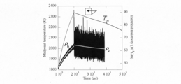
- FIG. 3 shows changes in the observed temperature T p of the sample when the molybdenum sample is heated by pulse current (value observed at the center of the sample with a radiation thermometer) and the electrical resistivity.
- the two white lines in FIG. 3 indicate approximate curves for the electrical resistivity measurement results when the sample is heated and when the temperature is decreased.
- the measured value of the voltage drop at both the temperature rise and the temperature drop always includes a constant voltage noise ⁇ V, and that ⁇ h and ⁇ c have the same magnitude, ⁇ V
- the measurement result of the electrical resistivity is corrected using the derived ⁇ V.
- the specific heat capacity is derived based on a false assumption that a steady voltage error is included in the measured voltage drop values of the sample and the standard resistor. Therefore, it is considered that a large error occurs when measuring a sample such as a carbon material measured by the inventor.
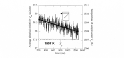
- FIG. 4 shows a measured value of the electrical resistivity ⁇ av of the molybdenum sample when the sample temperature T p is kept constant at the target temperature (1507 K) by the technique (2) described above (Non-Patent Document 4). . From this figure, it is recognized that the value of the electrical resistivity depending on the temperature changes with time even though the sample temperature is kept constant.
- the temperature measured by the radiation thermometer which is an observation parameter, only shows the temperature in a part of the center of the sample to be observed, and the temperature distribution of the entire sample is not uniform, so it represents the effective temperature of the sample. Indicates not to.
- the present invention improves the conventional measurement method of specific heat capacity and hemispherical total emissivity, solves the above-mentioned problems of electromagnetic interference noise and non-uniformity of sample temperature distribution with a low-cost apparatus, and conducts a conductive sample at a high temperature. It is an object to improve the accuracy of measurement results of specific heat capacity and hemispherical total emissivity.
- the present invention provides the following measuring method and apparatus.
- the conductive sample is rapidly heated, steps to reach the sample to the target temperature T m, immediately after reaching the target temperature by changing the electric current, the current flowing through the temperature change rate dT / dt immediately, the samples I Calculating the X and Y values from the measurement data of the voltage drop V of the sample using the following relational expression:
- the above specific heat capacity and hemispherical total emissivity measurement method is implemented, characterized by comprising means for automatically repeating a step of calculating a plurality of X and Y values by changing the current value after reaching the target temperature Device to do.
- a low-cost apparatus that does not have the temperature feedback control function required in the technique (2) described above eliminates the effects of electromagnetic interference noise and temperature distribution non-uniformity.
- the heat capacity and hemispherical total emissivity can be measured and the accuracy of measurement results can be easily improved by increasing the number of measurement points.
- by evaluating whether or not a plurality of X and Y values calculated from a plurality of measurements at the same target temperature have a linear relationship the presence or absence of a serious error in the measurement data can be determined. It is possible to self-check whether the feasible heat balance relational expression [Formula 1] has been established.
- Typical apparatus for implementing the specific heat capacity and hemispherical total emissivity measurement method based on the calorimetric method using the classical pulsed heating technique Time course of typical sample temperature obtained in the measurement method of specific heat capacity and hemispherical total emissivity based on the calorimetric method using the classical pulse current heating technique Discontinuous change in electrical resistivity of specimen before and after rapid heating by pulsed heating Temporal change in electrical resistivity during constant holding of sample temperature by feedback control pulse current heating Schematic view of a superimposed plurality of time variation curve obtained by changing the value of the target temperature T m gate voltage after reaching Schematic diagram of a specific heat capacity and the calculation method of the hemispherical total emissivity using the value of the target temperature T m was obtained from measurements obtained by implementing a plurality of different sample temperature change rate dT / dt under the same conditions X and Y The figure which plotted the value of X and Y obtained by the plurality of measurements of the carbon material actually performed on the XY plane
- Equation 8 indicates that a linear relationship is established between the values of X and Y calculated from the equations [Equation 9] and [Equation 10], respectively. Therefore, a linear expression of X and Y is approximately calculated by the least square method or the like for a plurality of X and Y values calculated by changing the current flowing through the sample to various values after reaching the target temperature, and the primary from the values of the slope and intercept of the approximate expression can be calculated specific heat capacity c p and hemispherical total emittance epsilon t at the target temperature T m.
- an apparatus that employs a semiconductor element such as a MOSFET as a current switch in the apparatus (see FIG. 1) that implements the technique (1) described above is required.
- the measurement is performed according to the following procedure.
- the sample was rapidly heated to the target temperature T m, and by changing the gate voltage V g to the MOSFET to a proper value, the current flowing through the sample I, voltage drop V corresponding to the sample, the temperature change rate dT / dt Each value is changed from the value immediately before the rapid heating is stopped.
- repeating the measurement with different values of the target temperature T m of a after reaching V g, to calculate the values of the various X and Y.
- the current flowing through the sample after reaching the target temperature may be of any magnitude, so that the gate voltages of the MOSFETs for adjusting the current are changed at a plurality of points at appropriate intervals to obtain I, V, and dT necessary for calculating X and Y.
- a device with a simple computer program function that repeats the measurement of / dt allows automatic measurement of specific heat capacity and hemispherical total emissivity.
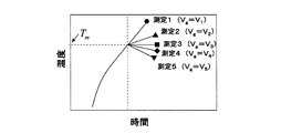
- FIG. 5 shows a schematic diagram when a plurality of sample temperature change curves obtained in the above-described plurality of measurements are superimposed.
- the first advantage of the present invention is that a measurement error caused by using measurement data of the sample temperature, current, and voltage drop immediately after reaching the target temperature by rapid heating in which electromagnetic interference noise and non-uniformity of the sample temperature distribution can be almost ignored. Reduction.
- the second advantage of the present invention is that it does not require the temperature feedback control function required in the technique (2) described above, and therefore can be implemented by a low-cost apparatus and is easy by increasing the measurement points of X and Y.
- the accuracy of the measurement results of specific heat capacity and hemispherical total emissivity can be improved.
- FIG. 7 shows a plurality of X and Y measurement results obtained by changing the value of the gate voltage after reaching the target temperature by the method of the present invention using a carbon material as a sample.
- the third advantage of the present invention is that it is possible to evaluate other measurement errors such as serious electromagnetic interference noise and sample deterioration by evaluating whether or not the obtained (X, Y) points have a linear relationship. It is possible to self-check whether or not there is a heat balance and whether or not the heat balance relationship in which the present invention can be implemented, that is, whether the formula [Equation 1] is satisfied.
- the fourth advantage of the present invention is that the current flowing through the sample after reaching the target temperature may be of any magnitude, so that the calculation of X and Y is performed by changing the gate voltage of the MOSFET for adjusting the current at multiple points at appropriate intervals.
- the specific heat capacity and hemispherical total emissivity can be automatically measured by a device having a simple computer program function that repeats the necessary I, V and dT / dt measurements.
Landscapes
- Physics & Mathematics (AREA)
- Health & Medical Sciences (AREA)
- Life Sciences & Earth Sciences (AREA)
- Chemical & Material Sciences (AREA)
- Analytical Chemistry (AREA)
- Biochemistry (AREA)
- General Health & Medical Sciences (AREA)
- General Physics & Mathematics (AREA)
- Immunology (AREA)
- Pathology (AREA)
- Investigating Or Analyzing Materials Using Thermal Means (AREA)
Abstract
本発明は、低コストな装置により上述の電磁干渉ノイズや試料温度分布の不均一性の問題を解決して高温における導電性試料の比熱容量及び半球全放射率の測定結果の確度を向上させることを課題とする。 導電性試料に通電して急速加熱し、該試料を目標温度Tmに到達させるステップ、目標温度に到達直後に該電流を変化させ、その直後の温度変化率dT/dt、試料を流れる電流I、試料の電圧降下Vの測定データから異なる該電流に対応する複数のXとYの値を次のXとYの関係式により算出するステップ、(式中のAは試料の有効表面積、σSBはステファン・ボルツマン定数、Tmは目標温度、T0は試料周囲の温度である。) 及び目標温度到達後の該電流を様々な値に変えた場合に得られる複数のXとYの値に対して、XとYが次式に示す線形関係を持つことを利用して、近似的に導出したXとYの1次式の傾きと切片の値から比熱容量cp及び半球全放射率εtを算出するステップを含むことを特徴とする導電性試料の比熱容量及び半球全放射率の測定方法及び装置。
Description
本発明は、高温における導電性試料の比熱容量及び半球全放射率の測定方法及び装置に関するものである。
高温における導電性試料の比熱容量及び半球全放射率の測定については従来より次のような熱量法を原理とする測定方法が採用されている。
(1)古典的なパルス通電加熱技術を利用した熱量法(非特許文献1参照)
(2)フィードバック制御パルス通電加熱技術を利用した熱量法(非特許文献2参照)
(3)試料の温度分布を考慮したパルス通電加熱技術を利用した熱量法(非特許文献3、4参照)
以下簡単に紹介する。
(1)古典的なパルス通電加熱技術を利用した熱量法(非特許文献1参照)
(2)フィードバック制御パルス通電加熱技術を利用した熱量法(非特許文献2参照)
(3)試料の温度分布を考慮したパルス通電加熱技術を利用した熱量法(非特許文献3、4参照)
以下簡単に紹介する。
古典的なパルス通電加熱技術を利用した熱量法は、1500K以上の高温における導電性試料の比熱容量と半球全放射率を測定する際に利用される一般的な方法である。この方法を実施するために使用される典型的な装置の概略を図1に示す。この方法では、試料にバッテリーを通じてパルス状の大電流を流して試料を瞬間的に加熱する。そして、その際の試料を流れる電流Iと試料における電圧降下V及び試料の温度Tを連続測定する。Iの値は、試料に直列接続した標準抵抗における電圧降下の測定値から算出すると共にTの値は放射温度計により測定して決定する。室温から急速に通電加熱された試料の中央付近の温度分布は短時間内では一様であり、試料から周囲への熱移動は熱放射が支配的であると仮定できるため、試料中央部での単位体積当たりの熱収支関係は次式[数1]で表される。

ここでmは、前述のVを測定する領域に対応する試料の有効質量、cpは試料の比熱容量、Aは前述のmに対応する試料の有効表面積、εtは試料の半球全放射率、σSBはステファン・ボルツマン定数、T0は試料周囲の温度である。
測定では図2に示すような温度変化を観測することになるが、電流を停止して試料が降温中であっても冷却開始直後であれば試料の温度分布が一様に保持されるとみなして[数1]が成立すると仮定する。この仮定の上で、昇温時(添字h)と降温時(添字c)における目標温度Tmにおける熱収支式はそれぞれ次式[数2]で表される。

そして、式[数2-1]、式[数2-2]を連立することにより比熱容量cpと半球全放射率εtを次式[数3]により算出することができる。

次に述べるフィードバック制御パルス通電加熱技術を利用した熱量法は、(1)の技術を発展させた方法である。(1)の技術との違いは、電流制御スイッチにMOSFET等の半導体素子を用いることにより電流のON/OFFのみならず試料温度を基準パラメータとして電流をフィードバック制御することにより試料温度を短時間だけ温度一定に保持する機能を有する点である。この機能により試料を目標温度Tmの定常状態に保持した場合には上記[数1]の左辺は零とみなせるため、半球全放射率εtは次式[数4]により算出できる。

更に、得られた半球全放射率と加熱時の温度変化から次式[数5]により比熱容量を算出することができる。

次に述べる試料の温度分布を考慮したパルス通電加熱技術を利用した熱量法による比熱容量の測定方法は、(1)の技術を発展させた方法である。(1)の方法との違いは、冷却中の試料の温度とその時間変化率として放射温度計が測定する値ではなく、電気抵抗率の値から導出した温度を用いる点である。電気抵抗率から導出した温度を用いる理由は、急速加熱が終了して試料が冷却状態になると試料の温度分布は伝導熱損失の影響により急速に不均一になるため、単に試料表面の一部のみを観測する放射温度計が示す温度は試料全体の温度分布を考慮した実効温度と偏差を生じるためである。(3)の技術による比熱容量の具体的な実施方法は、急速加熱により目標温度Tmへ到達させた後も電流をわずかに流すことにより4端子法原理による電気抵抗率測定を冷却中も継続し、得られた電気抵抗率の値から実効的な温度を算出し、その実効温度を式[数3-1]中に代入して比熱容量を算出する(非特許文献3)。
また、温度分布を考慮したパルス通電加熱技術を利用した熱量法による半球全放射率の測定方法は、(2)の技術を発展させた方法である。この方法では、電流のフィードバック制御により試料温度を一定に保持した上で同時に測定される電気抵抗率の値から算出される実効的な温度の変動に対応するエンタルピー減少や伝導熱損失の効果を考慮した解析により半球全放射率を算出する(非特許文献4)。
また、温度分布を考慮したパルス通電加熱技術を利用した熱量法による半球全放射率の測定方法は、(2)の技術を発展させた方法である。この方法では、電流のフィードバック制御により試料温度を一定に保持した上で同時に測定される電気抵抗率の値から算出される実効的な温度の変動に対応するエンタルピー減少や伝導熱損失の効果を考慮した解析により半球全放射率を算出する(非特許文献4)。
A. Cezairliyan, J. L. McClure, and C. W. Beckett: J. Res. National Bureau of Standards, Vol. 75C, 7(1971).
T. Matsumoto and A. Cezairliyan: Int. J. Thermophys. Vol. 18, 1539 (1997).
H. Watanabe: Rev. Sci. Instrum., Vol. 77, 036110 (2006).
H. Watanabe and T. Matsumoto: Rev. Sci. Instrum., Vol. 76, 043904 (2005).
(従来技術の問題点)
パルス通電加熱法により試料を急速加熱する際、導電性試料を流れる電流は大きく時間変動する場合が多い。電流の時間変化は、電磁干渉ノイズを発生させ、試料と標準抵抗におけるそれぞれの電圧降下の測定に大きな誤差を与えることがある。
図3にモリブデン試料をパルス通電加熱した際の試料の観測温度Tp(試料中心部を放射温度計で観測した値)と電気抵抗率の時間変化を示す。図3中の2本の白線は、試料の昇温時と降温時それぞれの電気抵抗率測定結果についての近似曲線を示す。この測定では、加熱開始から約2×10⁵μsの時間経過後に急速加熱を停止しており、その直前直後における試料の昇温時と降温時の電気抵抗率(ρhとρc)を比較すると系統的な差が存在することが判る。電気抵抗率は試料の温度が同じであれば一致するはずなので、このような電気抵抗率の違いは、試料及び標準抵抗の電圧降下の測定値に何らかの誤差が含まれることを明示している。渡辺と松本は、その誤差要因として電圧降下の測定機器のゼロ点補正の誤りのような常に一定の値で測定値に含まれる定常的な電圧ノイズであるとの考察を報告している(非特許文献3)。同報告によれば、昇温時と降温時どちらの電圧降下の測定値も常に一定の電圧ノイズΔVが含まれると仮定した上で、ρhとρcは同じ大きさであるという関係からΔVを導出し、導出したΔVを用いて電気抵抗率の測定結果を補正している。
パルス通電加熱法により試料を急速加熱する際、導電性試料を流れる電流は大きく時間変動する場合が多い。電流の時間変化は、電磁干渉ノイズを発生させ、試料と標準抵抗におけるそれぞれの電圧降下の測定に大きな誤差を与えることがある。
図3にモリブデン試料をパルス通電加熱した際の試料の観測温度Tp(試料中心部を放射温度計で観測した値)と電気抵抗率の時間変化を示す。図3中の2本の白線は、試料の昇温時と降温時それぞれの電気抵抗率測定結果についての近似曲線を示す。この測定では、加熱開始から約2×10⁵μsの時間経過後に急速加熱を停止しており、その直前直後における試料の昇温時と降温時の電気抵抗率(ρhとρc)を比較すると系統的な差が存在することが判る。電気抵抗率は試料の温度が同じであれば一致するはずなので、このような電気抵抗率の違いは、試料及び標準抵抗の電圧降下の測定値に何らかの誤差が含まれることを明示している。渡辺と松本は、その誤差要因として電圧降下の測定機器のゼロ点補正の誤りのような常に一定の値で測定値に含まれる定常的な電圧ノイズであるとの考察を報告している(非特許文献3)。同報告によれば、昇温時と降温時どちらの電圧降下の測定値も常に一定の電圧ノイズΔVが含まれると仮定した上で、ρhとρcは同じ大きさであるという関係からΔVを導出し、導出したΔVを用いて電気抵抗率の測定結果を補正している。
しかし、本発明者は炭素材料について前述のモリブデンと同様な測定を行った結果、急速加熱を停止する直前直後における電気抵抗率の見かけ上の不連続現象の原因は、試料を流れる電流の大きな時間変化を伴う急速加熱時にのみ発生する電磁干渉ノイズであるとの結論に至った。なぜなら、本発明者が測定した炭素材料のρhとρcの値を信頼できる文献値と比較した結果、ρcは文献値とほぼ一致したがρhは大きく文献値と異なったからである。ρhにのみ大きな誤差が含まれた原因が渡辺と松本が主張する定常的な電圧ノイズと仮定すると、あまりに大きな電圧ノイズが定常的に生じていることになる。一方、電磁干渉ノイズの大きさは電流の時間変化の大きさに比例するので、電流の大きな時間変動を伴う急速加熱時の電気抵抗率の測定値にのみ大きな誤差が含まれることは十分考えられる。
これまでの議論から、急速加熱中のIとVの測定値を用いる式[数3-1]、[数3-2]、[数5]により算出した比熱容量と半球全放射率の値には電磁干渉ノイズを起因とする大きな誤差が含まれる可能性がある。また、非特許文献3に記載された比熱容量の測定法では、試料及び標準抵抗の電圧降下の測定値に定常的な電圧誤差が含まれるとの誤った仮定の基で比熱容量が導出されるため、本発明者が測定を行った炭素材料のような試料を測定する場合には、大きな誤差が生じると考えられる。
これまでの議論から、急速加熱中のIとVの測定値を用いる式[数3-1]、[数3-2]、[数5]により算出した比熱容量と半球全放射率の値には電磁干渉ノイズを起因とする大きな誤差が含まれる可能性がある。また、非特許文献3に記載された比熱容量の測定法では、試料及び標準抵抗の電圧降下の測定値に定常的な電圧誤差が含まれるとの誤った仮定の基で比熱容量が導出されるため、本発明者が測定を行った炭素材料のような試料を測定する場合には、大きな誤差が生じると考えられる。
[数4]により半球全放射率を測定する場合には、急速加熱時の電圧測定値を使わないため電磁干渉ノイズの問題はほぼ無視できる。しかし、次に示すような問題点が指摘されている。モリブデン試料について上述の(2)の技術により試料温度Tpを目標温度(1507K)に一定保持した際の試料の電気抵抗率ρavの測定値を図4に示している(非特許文献4)。この図から、試料温度を一定に保持しているにもかかわらず、温度に依存する電気抵抗率の値が時間変化することが認められる。このことは、試料に接触している電流供給のためのホルダーや電圧降下測定用のプローブを介した伝導熱損失により、温度分布の不均一化が進行していることを示している。つまり、観測パラメータである放射温度計が測定する温度は観測する試料中心の一部の範囲の温度を示しているに過ぎず、試料全体の温度分布が均一でないため試料の実効的な温度を代表しないことを示す。
図4に示された試料中心温度と電気抵抗率の温度係数の不一致は、前述の(2)の技術による半球全放射率の算出に使われる式[数4]が厳密には成立しないことを示している。非特許文献4に記載された半球全放射率の測定法は、この問題の1つの解決法として提案されたが、半球全放射率を算出するためには比熱容量と熱伝導率及び試料の温度分布とその経時変化を測定する必要があるという大きな制限がある。
(本発明の解決課題)
本発明は、従来の比熱容量及び半球全放射率の測定方法を改良し、低コストな装置により上述の電磁干渉ノイズや試料温度分布の不均一性の問題を解決して高温における導電性試料の比熱容量及び半球全放射率の測定結果の確度を向上させることを課題とする。
本発明は、従来の比熱容量及び半球全放射率の測定方法を改良し、低コストな装置により上述の電磁干渉ノイズや試料温度分布の不均一性の問題を解決して高温における導電性試料の比熱容量及び半球全放射率の測定結果の確度を向上させることを課題とする。
上記課題を解決するために本発明は、次のような測定方法及び装置を提供する。
導電性試料に通電して急速加熱し、該試料を目標温度Tmに到達させるステップ、目標温度に到達直後に該電流を変化させ、その直後の温度変化率dT/dt、試料を流れる電流I、試料の電圧降下Vの測定データから次の関係式を用いてXとYの値を算出するステップ、
導電性試料に通電して急速加熱し、該試料を目標温度Tmに到達させるステップ、目標温度に到達直後に該電流を変化させ、その直後の温度変化率dT/dt、試料を流れる電流I、試料の電圧降下Vの測定データから次の関係式を用いてXとYの値を算出するステップ、

及び目標温度到達後の該電流を様々な値に変えた場合に得られる複数のXとYの値に対して、XとYが次式に示す線形関係を持つことを利用して、近似的に導出したXとYの1次式の傾きと切片の値から比熱容量cp及び半球全放射率εtを算出するステップを含むことを特徴とする導電性試料の比熱容量及び半球全放射率の測定方法。

目標温度到達後の電流値を変えることにより複数のXとYの値を算出するステップを自動的に繰り返す手段を備えたことを特徴とする上記の比熱容量と半球全放射率の測定方法を実施する装置。
本発明によれば、上述の(2)の技術において必要とした温度のフィードバック制御機能を有さない低コストの装置により、電磁干渉ノイズと温度分布の不均一性の影響を廃した上で比熱容量と半球全放射率を測定できると共に測定点を増やすことで容易に測定結果の確度を向上させることができる。
また本発明によれば、同じ目標温度における複数の測定から算出した複数のXとYの値が線形関係を持つかどうかを評価することにより、測定データ中の深刻な誤差の有無や本発明が実施可能な熱収支関係式[数1]が成立していたかどうかをセルフチェックできる。
また本発明によれば、同じ目標温度における複数の測定から算出した複数のXとYの値が線形関係を持つかどうかを評価することにより、測定データ中の深刻な誤差の有無や本発明が実施可能な熱収支関係式[数1]が成立していたかどうかをセルフチェックできる。
本発明に係る導電性試料の比熱容量及び半球全放射率の測定方法の概要を説明する。
本発明は、上述の2つの誤差要因の影響を低減するため、電磁干渉ノイズと試料温度分布の不均一性が小さい急速加熱した直後の測定データを利用して目標温度Tmにおける比熱容量cpと半球全放射率εtを算出することを目的とする。大電流により試料を目標温度に急速加熱した直後であれば、試料温度分布の不均一性や伝導熱損失の影響はほぼ無視できるため試料の熱収支について式[数1]が成立する。そして、式[数1]は、以下のように変形することができる。
本発明は、上述の2つの誤差要因の影響を低減するため、電磁干渉ノイズと試料温度分布の不均一性が小さい急速加熱した直後の測定データを利用して目標温度Tmにおける比熱容量cpと半球全放射率εtを算出することを目的とする。大電流により試料を目標温度に急速加熱した直後であれば、試料温度分布の不均一性や伝導熱損失の影響はほぼ無視できるため試料の熱収支について式[数1]が成立する。そして、式[数1]は、以下のように変形することができる。



上述の式[数8]は、式[数9]と式[数10]からそれぞれ算出されるXとYの値の間には線形関係が成立することを示している。したがって、目標温度到達後に試料に流す電流を様々な値に変えることで算出した複数のXとYの値に対して最小自乗法等によりXとYの一次式を近似的に算出し、その一次近似式の傾きと切片の値から目標温度Tmにおける比熱容量cpと半球全放射率εtを算出できる。
本発明を実施するためには、上述の(1)の技術を実施する装置(図1参照)において電流スイッチとしてMOSFET等の半導体素子を採用した装置が必要である。
測定は、以下の手順により行う。
試料を目標温度Tmに急速加熱した後、MOSFETへのゲート電圧Vgを適当な値に変化させることで、試料に流れる電流I、試料に対応する電圧降下V、温度変化率dT/dtのそれぞれの値について急速加熱を停止する直前の値から変化させる。次に、目標温度Tm到達後のVgの値を変えた測定を繰り返し、さまざまなXとYの値を算出する。
これは例えば図1に示す装置において、複数のXとYの値を求めるために目標温度到達後の電流値を変えてXとYの値を算出するステップを自動的に繰り返す手段を設けることにより実施される。
すなわち目標温度到達後の試料に流す電流は任意の大きさで構わないため、電流を調整するMOSFETのゲート電圧を適当な間隔で複数点変えてXとYの算出に必要なI、V及びdT/dtの測定を繰り返す簡単なコンピュータ・プログラム機能を有する装置により、比熱容量と半球全放射率の自動測定が可能となる。
図5に、前述の複数の測定において得られた複数の試料温度変化曲線を重ね合わせた場合の模式図を示す。このようにして得られた複数の測定に対応するXとYの値を算出し、図6に示すようにXとYの直線関係を導出することによりTmにおけるcpとεtを算出できる。
測定は、以下の手順により行う。
試料を目標温度Tmに急速加熱した後、MOSFETへのゲート電圧Vgを適当な値に変化させることで、試料に流れる電流I、試料に対応する電圧降下V、温度変化率dT/dtのそれぞれの値について急速加熱を停止する直前の値から変化させる。次に、目標温度Tm到達後のVgの値を変えた測定を繰り返し、さまざまなXとYの値を算出する。
これは例えば図1に示す装置において、複数のXとYの値を求めるために目標温度到達後の電流値を変えてXとYの値を算出するステップを自動的に繰り返す手段を設けることにより実施される。
すなわち目標温度到達後の試料に流す電流は任意の大きさで構わないため、電流を調整するMOSFETのゲート電圧を適当な間隔で複数点変えてXとYの算出に必要なI、V及びdT/dtの測定を繰り返す簡単なコンピュータ・プログラム機能を有する装置により、比熱容量と半球全放射率の自動測定が可能となる。
図5に、前述の複数の測定において得られた複数の試料温度変化曲線を重ね合わせた場合の模式図を示す。このようにして得られた複数の測定に対応するXとYの値を算出し、図6に示すようにXとYの直線関係を導出することによりTmにおけるcpとεtを算出できる。
本発明の第1の利点は、電磁干渉ノイズや試料温度分布の不均一性がほぼ無視できる急速加熱により目標温度に到達した直後の試料温度、電流、電圧降下の測定データを用いることによる測定誤差の低減である。
本発明の第2の利点は、上述の(2)の技術において必要とした温度のフィードバック制御機能を必要としないため、低コストの装置により実施できると共にXとYの測定点を増やすことで容易に比熱容量と半球全放射率の測定結果の確度を向上させることができることである。実際にある炭素材料を試料として本発明の方法により、目標温度到達後のゲート電圧の値を変えて得られた複数のXとYの測定結果を図7に示す。
この図からXの値が8前後の点は明らかに線形関係からずれているが、これらの点は目標温度到達後もかなり大きな温度上昇率が生じるようにゲート電圧を設定した際の測定結果から導出した点である。この場合、明らかに試料温度の急激な上昇に付随する試料の電気抵抗率の変化に応じて試料に流れる電流が大きく時間変動してしまい、結果として深刻な電磁干渉ノイズが電圧測定値に含まれてしまったことを示している。このような、XとYの線形関係からのずれは、試料の熱収支関係が式[数1]に表される理想的な状態からずれてしまうことによって生じる。したがって、電磁干渉ノイズ以外の測定誤差要因例えば試料の汚染等が複数回繰り返す測定のいずれかにおいて発生した場合、その測定から得られる(X,Y)点は他の正常な測定から得られた(X,Y)点が構成する直線からずれることになる。
本発明の第2の利点は、上述の(2)の技術において必要とした温度のフィードバック制御機能を必要としないため、低コストの装置により実施できると共にXとYの測定点を増やすことで容易に比熱容量と半球全放射率の測定結果の確度を向上させることができることである。実際にある炭素材料を試料として本発明の方法により、目標温度到達後のゲート電圧の値を変えて得られた複数のXとYの測定結果を図7に示す。
この図からXの値が8前後の点は明らかに線形関係からずれているが、これらの点は目標温度到達後もかなり大きな温度上昇率が生じるようにゲート電圧を設定した際の測定結果から導出した点である。この場合、明らかに試料温度の急激な上昇に付随する試料の電気抵抗率の変化に応じて試料に流れる電流が大きく時間変動してしまい、結果として深刻な電磁干渉ノイズが電圧測定値に含まれてしまったことを示している。このような、XとYの線形関係からのずれは、試料の熱収支関係が式[数1]に表される理想的な状態からずれてしまうことによって生じる。したがって、電磁干渉ノイズ以外の測定誤差要因例えば試料の汚染等が複数回繰り返す測定のいずれかにおいて発生した場合、その測定から得られる(X,Y)点は他の正常な測定から得られた(X,Y)点が構成する直線からずれることになる。
したがって、本発明の第3の利点は、得られた複数の(X,Y)点が線形関係を持つかどうかを評価することにより、深刻な電磁干渉ノイズや試料の変質などのその他の測定誤差の有無や本発明が実施可能な熱収支関係すなわち式[数1]が成立していたかどうかをセルフチェックできることである。
本発明の第4の利点は、目標温度到達後の試料に流す電流は任意の大きさで構わないため、電流を調整するMOSFETのゲート電圧を適当な間隔で複数点変えてXとYの算出に必要なI、V及びdT/dtの測定を繰り返す簡単なコンピュータ・プログラム機能を有する装置により、比熱容量と半球全放射率の自動測定が可能である点である。
本発明の第4の利点は、目標温度到達後の試料に流す電流は任意の大きさで構わないため、電流を調整するMOSFETのゲート電圧を適当な間隔で複数点変えてXとYの算出に必要なI、V及びdT/dtの測定を繰り返す簡単なコンピュータ・プログラム機能を有する装置により、比熱容量と半球全放射率の自動測定が可能である点である。
Claims (2)
- 導電性試料に通電して急速加熱し、該試料を目標温度Tmに到達させるステップ、目標温度に到達直後に該電流を変化させ、その直後の温度変化率dT/dt、試料を流れる電流I、試料の電圧降下Vの測定データから次の関係式を利用してXとYを算出するステップ、
(式中のAは試料の有効表面積、σSBはステファン・ボルツマン定数、Tmは目標温度、T0は試料周囲の温度である。)
及び該複数のXとYの値に対して、XとYが次式に示す線形関係を持つことを利用して、近似的に導出したXとYの1次式の傾きと切片の値から比熱容量cp及び半球全放射率εtを算出するステップを含むことを特徴とする導電性試料の比熱容量及び半球全放射率の測定方法。

- 目標温度到達後の電流値を変えることにより複数のXとYの値を算出するステップを自動的に繰り返す手段を備えたことを特徴とする請求項1に記載の比熱容量と半球全放射率の測定方法を実施する装置。
Applications Claiming Priority (2)
| Application Number | Priority Date | Filing Date | Title |
|---|---|---|---|
| JP2009052886A JP4528954B1 (ja) | 2009-03-06 | 2009-03-06 | 導電性試料の比熱容量及び半球全放射率の測定方法及び装置 |
| JP2009-052886 | 2009-03-06 |
Publications (1)
| Publication Number | Publication Date |
|---|---|
| WO2010101006A1 true WO2010101006A1 (ja) | 2010-09-10 |
Family
ID=42709568
Family Applications (1)
| Application Number | Title | Priority Date | Filing Date |
|---|---|---|---|
| PCT/JP2010/051922 Ceased WO2010101006A1 (ja) | 2009-03-06 | 2010-02-10 | 導電性試料の比熱容量及び半球全放射率の測定方法及び装置 |
Country Status (2)
| Country | Link |
|---|---|
| JP (1) | JP4528954B1 (ja) |
| WO (1) | WO2010101006A1 (ja) |
Cited By (2)
| Publication number | Priority date | Publication date | Assignee | Title |
|---|---|---|---|---|
| CN103364434A (zh) * | 2013-04-24 | 2013-10-23 | 清华大学 | 大温差样品的半球向全发射率的测量方法 |
| JP2020101462A (ja) * | 2018-12-21 | 2020-07-02 | 国立研究開発法人産業技術総合研究所 | 比熱とエンタルピー変化の測定方法および測定装置 |
Families Citing this family (2)
| Publication number | Priority date | Publication date | Assignee | Title |
|---|---|---|---|---|
| JP5414068B2 (ja) * | 2010-09-15 | 2014-02-12 | 独立行政法人産業技術総合研究所 | 導電性試料の比熱容量及び半球全放射率の測定方法及び装置 |
| CN109916952B (zh) * | 2019-04-12 | 2024-01-19 | 中国工程物理研究院化工材料研究所 | 空心圆球构型的表面对流换热系数测量系统及测量方法 |
Citations (4)
| Publication number | Priority date | Publication date | Assignee | Title |
|---|---|---|---|---|
| JPH03237345A (ja) * | 1990-02-14 | 1991-10-23 | Agency Of Ind Science & Technol | 熱伝導率測定方法 |
| JPH10160590A (ja) * | 1996-11-26 | 1998-06-19 | Agency Of Ind Science & Technol | 平行三層モデルを用いた熱拡散率の測定法 |
| JP2006329969A (ja) * | 2005-04-25 | 2006-12-07 | National Institute Of Advanced Industrial & Technology | 比熱容量測定方法及び装置 |
| JP2009025279A (ja) * | 2007-07-19 | 2009-02-05 | Heatrad Corp | 物体表面の半球熱放射率の測定方法 |
-
2009
- 2009-03-06 JP JP2009052886A patent/JP4528954B1/ja not_active Expired - Fee Related
-
2010
- 2010-02-10 WO PCT/JP2010/051922 patent/WO2010101006A1/ja not_active Ceased
Patent Citations (4)
| Publication number | Priority date | Publication date | Assignee | Title |
|---|---|---|---|---|
| JPH03237345A (ja) * | 1990-02-14 | 1991-10-23 | Agency Of Ind Science & Technol | 熱伝導率測定方法 |
| JPH10160590A (ja) * | 1996-11-26 | 1998-06-19 | Agency Of Ind Science & Technol | 平行三層モデルを用いた熱拡散率の測定法 |
| JP2006329969A (ja) * | 2005-04-25 | 2006-12-07 | National Institute Of Advanced Industrial & Technology | 比熱容量測定方法及び装置 |
| JP2009025279A (ja) * | 2007-07-19 | 2009-02-05 | Heatrad Corp | 物体表面の半球熱放射率の測定方法 |
Non-Patent Citations (3)
| Title |
|---|
| HIROMICHI WATANABE ET AL.: "New analysis for determination of hemispherical total emissivityby feedback-controlled pulse- heating technique", REVIEW OF SCIENTIFIC INSTRUMENTS, vol. 76, 23 March 2005 (2005-03-23), pages 043904 * |
| HIROMICHI WATANABE: "Ceramics ni Okeru Netsu Sokutei-Netsu Bunseki Hikari Tsuden Hybrid Pulse Kanetsu o Riyo shita Kosoku Taju Netsu Bussei Sokutei to Hikari Heterodyne Kanshoshiki Netsu Bocho Sokutei", CERAMICS, vol. 42, no. 12, 1 December 2007 (2007-12-01), pages 930 - 935 * |
| HIROMICHI WATANABE: "Novel pulse calorimetry taking nonuniform temperature distributioninto account", REVIEW OF SCIENTIFIC INSTRUMENTS, vol. 77, 27 March 2006 (2006-03-27), pages 036110 * |
Cited By (3)
| Publication number | Priority date | Publication date | Assignee | Title |
|---|---|---|---|---|
| CN103364434A (zh) * | 2013-04-24 | 2013-10-23 | 清华大学 | 大温差样品的半球向全发射率的测量方法 |
| JP2020101462A (ja) * | 2018-12-21 | 2020-07-02 | 国立研究開発法人産業技術総合研究所 | 比熱とエンタルピー変化の測定方法および測定装置 |
| JP7250268B2 (ja) | 2018-12-21 | 2023-04-03 | 国立研究開発法人産業技術総合研究所 | 比熱とエンタルピー変化の測定方法 |
Also Published As
| Publication number | Publication date |
|---|---|
| JP2010204063A (ja) | 2010-09-16 |
| JP4528954B1 (ja) | 2010-08-25 |
Similar Documents
| Publication | Publication Date | Title |
|---|---|---|
| KR102848261B1 (ko) | 전기 히터를 작동시키는 제어 시스템을 교정하는 시스템 및 방법 | |
| CN109781776A (zh) | 一种可同时测量材料多个热电参数的装置及方法 | |
| JP2011185697A (ja) | 熱電材料評価装置及び熱電特性評価方法 | |
| Taylor et al. | The specific heats and resistivities of molybdenum, tantalum, and rhenium | |
| JP4528954B1 (ja) | 導電性試料の比熱容量及び半球全放射率の測定方法及び装置 | |
| JP6202580B2 (ja) | 熱物性測定方法及び熱物性測定装置 | |
| CN109613054B (zh) | 一种直接通电纵向导热系数测试方法 | |
| KR102730371B1 (ko) | 저항성 히터의 수동 및 능동 교정 방법 | |
| Liu et al. | Reliable measurements of the Seebeck coefficient on a commercial system | |
| JP5414068B2 (ja) | 導電性試料の比熱容量及び半球全放射率の測定方法及び装置 | |
| JP6607469B2 (ja) | 熱物性測定方法及び熱物性測定装置 | |
| JP7250268B2 (ja) | 比熱とエンタルピー変化の測定方法 | |
| JP7033292B2 (ja) | 熱電物性測定装置及び熱電物性測定方法 | |
| JP2006329969A (ja) | 比熱容量測定方法及び装置 | |
| CN105785102B (zh) | 微尺度样品的热电势测量电路、平台及方法 | |
| RU2716466C1 (ru) | Способ контроля теплофизических свойств материалов и устройство для его осуществления | |
| Ronnpagel | A new method of deformation calorimetry | |
| Goldsmid | Measuring the thermoelectric properties | |
| JP3834633B2 (ja) | 超高温度測定装置および超高温度用ガスセンサー | |
| CN116298593A (zh) | 一种电阻丝快速寿命测试方法 | |
| Glaeser | Stabilization and regulation of temperature for quenching and annealing experiments with a metal wire | |
| JP2006114580A (ja) | 温度測定装置及びプラズマ処理装置 |
Legal Events
| Date | Code | Title | Description |
|---|---|---|---|
| 121 | Ep: the epo has been informed by wipo that ep was designated in this application |
Ref document number: 10748603 Country of ref document: EP Kind code of ref document: A1 |
|
| NENP | Non-entry into the national phase |
Ref country code: DE |
|
| 122 | Ep: pct application non-entry in european phase |
Ref document number: 10748603 Country of ref document: EP Kind code of ref document: A1 |