WO2010100755A1 - スライドファスナー用スライダー - Google Patents
スライドファスナー用スライダー Download PDFInfo
- Publication number
- WO2010100755A1 WO2010100755A1 PCT/JP2009/054301 JP2009054301W WO2010100755A1 WO 2010100755 A1 WO2010100755 A1 WO 2010100755A1 JP 2009054301 W JP2009054301 W JP 2009054301W WO 2010100755 A1 WO2010100755 A1 WO 2010100755A1
- Authority
- WO
- WIPO (PCT)
- Prior art keywords
- slider
- handle
- arm
- portions
- slider body
- Prior art date
- Legal status (The legal status is an assumption and is not a legal conclusion. Google has not performed a legal analysis and makes no representation as to the accuracy of the status listed.)
- Ceased
Links
Images


Classifications
-
- A—HUMAN NECESSITIES
- A44—HABERDASHERY; JEWELLERY
- A44B—BUTTONS, PINS, BUCKLES, SLIDE FASTENERS, OR THE LIKE
- A44B19/00—Slide fasteners
- A44B19/24—Details
- A44B19/26—Sliders
- A44B19/262—Pull members; Ornamental attachments for sliders
Definitions
- the present invention relates to a slider having a handle that is operated when the slide fastener is opened and closed, and more particularly to a slider that can be removed when the slider is not operated.
- the conventional slider that opens and closes the slide fastener is provided with a handle for the user to grip and move the slider.
- the shaft part of the handle is inserted between the front and rear pillars standing on the upper surface of the slider body.
- it covers with the cover so that the upper part between pillar parts may be closed, and this cover is crimped to a pillar part, and a bearing hole is formed.
- the handle is tiltably supported with respect to the slider body by loosely fitting the handle shaft portion into the bearing hole.
- the slider body and the handle are not separated thereafter.
- Patent Document 1 a slider that can be used to replace the handle according to the user's preference is disclosed in Japanese Patent Publication No. 7-55161 (Patent Document 1).
- a handle attachment rod having a bearing hole for loosely fitting the handle shaft portion is erected.
- the puller attachment rod extends toward the rear end side of the slider body, and forms a rear end protrusion that closes the upper half of the bearing hole. Between the rear end protrusion and the upper surface of the slider body, a gap that allows the handle shaft to pass therethrough is formed.
- a closing body that is slidable in the front-rear direction of the slider body is disposed in a gap formed between the upper surface of the rear part of the slider body and the lower part of the rear end protruding portion of the pull handle attachment rod.
- a sliding projection is formed on the closing body, and when the closing body is in a free state, the sliding projection of the closing body is biased to a position facing the rear end protrusion of the pull handle attachment rod. Is stopped and the gap is closed.
- the slider described in Patent Document 1 uses a temporary puller that is easy to remove and is premised on replacement.
- the tip portion of the temporary handle is formed in an annular shape, and a fragile portion that can be cut is formed in a part of the annular portion.
- the user pulls the temporary handle and twists the slider body.
- the weakened portion of the handle shaft portion is broken.
- the knob part of the temporary puller is further twisted, the broken weak part is separated.
- Patent Document 2 discloses a slider in which a handle is configured to be detachable from a slider body.
- the handle shaft portion of the handle is formed in a shape protruding from the left and right, and a gap w is formed in the center portion.
- the slider main body is provided with a hook-shaped pulling attachment rod formed with a plate thinner than the gap w and having bearing holes in both side walls.
- the slider described in Patent Document 2 has a problem in that it is impossible to remove the handle unless it is moved and reversed without losing the handle while ordering so as to solve the circle of wisdom. Arise. Although the handle is difficult to remove as described above, there is a problem that the handle naturally disengages from the slider body when vibration is intermittently applied during transportation.
- the present invention has been made in view of such problems, and in a slider in which a part of the handle shaft part can be separated and the handle can be detached from the slider body, a part of the handle part is separated.
- An object of the present invention is to provide a slider capable of preventing the breakage of other parts in the pulling handle and preventing the generation of broken pieces even in the case of being made.
- a slider for a slide fastener includes a slider body having a pillar portion formed with a bearing hole for supporting the handle so that the handle can be tilted on an upper surface, and a handle shaft inserted into the bearing hole at one end. And a handle having a knob portion extending through a pair of left and right symmetrical arms from both side end portions to the other end side of the handle shaft portion, and an inner surface facing the bearing hole.
- the reference inner method is A
- the width of the column part is Z
- the loose fitting outer method of the pulling shaft part is a
- the pair of locking overhanging parts are formed symmetrically on both ends of the pulling shaft part.
- z ⁇ 1.5 ⁇ Z and j> 2 ⁇ Z are satisfied among the column width Z, the loose fitting range z, and the arm maximum inner method j. It is characterized by that.
- j + d> 3 ⁇ Z is satisfied, where d is the width of the arm portion in the portion of the maximum inner portion of the arm portion j.
- the arm portion length l is 8 (mm) or more
- the arm portion width d is 1.2 (mm) or less
- the arm portion The maximum inner method j is formed to be 7 (mm) or more.
- a fragile portion in which the left and right pulling shaft portions are connected in a breakable manner is formed in the alternately separated portions.
- the slider according to the present invention has a bearing hole of the standard inner method A that supports the handle so that the handle can be tilted on the column portion erected on the upper surface of the slider body, and is provided at both end sides of the handle shaft portion inserted through the bearing hole.
- a symmetric locking overhanging portion formed in the overhanging outside method b larger than the reference inner method A is formed, and the loose fitting range z which is the interval between the locking overhanging portions is defined as the column width in the slider body. It was set to be wider than Z and narrower than the arm maximum inner method j in the handle. And the alternately separated part was formed in the center part of the loose fitting range z in a pulling shaft part.
- the tensile stress and the shear stress applied to both arms of the handle can be made substantially symmetrical. Then, when the alternately separated portions are separated and the handle is removed from the slider main body, it is possible to reduce a problem that breakage occurs when a large stress is applied to one arm portion.
- the loose fitting range z that is the interval between the locking overhang portions is set to be greater than the column width Z and less than 1.5 times the column width Z
- Method j was set to be larger than twice the column width Z.
- the interval between the arm portions is set to be three times or more of the column width Z, the alternate opening portions are separated and the arms are added when the handle is removed from the slider body.
- the shear stress can be reduced, and the trouble that the arm portion breaks can be reduced.
- the arm part length l to 8 (mm) or more, the arm part width d to 1.2 (mm) or less, and the arm part maximum inner dimension j to 7 (mm) or more are formed.
- the left and right handle shafts are connected in a breakable manner in the alternate opening portions, so that when the slider is slid with a strong operating force, the handle is twisted and detached from the slider body. It is possible to reduce malfunctions.
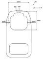
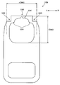
- FIG. 1 is a plan view of a slider according to the present invention observed from above.
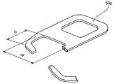
- FIG. 2 is a plan view of a single handle in the slider shown in FIG.
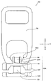
- FIG. 3 is a front view of the slider shown in FIG. 1 observed from the rear opening side.
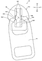
- FIG. 4 is a diagram showing a state in which the handle is tilted in the horizontal plane in the slider shown in FIG.
- FIG. 5 is a diagram showing a state in which the handle is tilted in the vertical plane in the slider shown in FIG.
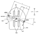
- FIG. 6 is a partial cross-sectional view for explaining the shearing force applied to the alternately separated portions when the handle is twisted in the slider shown in FIG.
- FIG. 1 is a plan view of a slider according to the present invention observed from above.
- FIG. 2 is a plan view of a single handle in the slider shown in FIG.
- FIG. 3 is a front view of the slider shown in FIG. 1 observed from the rear opening side.
- FIG. 4 is a diagram showing
- FIG. 7 is a partial cross-sectional view illustrating a state where the handle is twisted clockwise from the state shown in FIG.
- FIG. 8 is a partial cross-sectional view for explaining a state in which the handle is further twisted clockwise from the state shown in FIG. 7 and can be detached from the slider body.
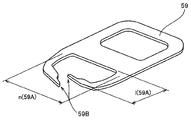
- FIG. 9 is an external perspective view of the detached handle.
- FIG. 10 is a partial cross-sectional view for explaining a case where a pull handle having a narrow arm interval is twisted clockwise to be removable from the slider body.
- FIG. 11 is an external perspective view of a handle for explaining a state in which the arm portion is broken when a handle having a narrow arm portion interval is removed from the slider body.
- FIG. 12 is a plan view of a single handle for explaining an embodiment in which a notch is formed on the opposite side of the overhang in order to reduce the secondary moment of inertia in the vicinity of the overhang of the pull.
- FIG. 13 is a plan view of a single handle for explaining an embodiment in which a gap is formed at alternate opening portions of the handle to form a non-connecting portion.
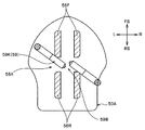
- FIG. 1 is a plan view of a slider 50 according to the present invention observed from above.
- FIG. 2 is a plan view of a single handle 59 attached to the slider 50 shown in FIG.
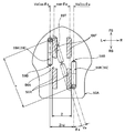
- FIG. 3 is a front view of the slider 50 shown in FIG.
- the front of the slider 50 is defined as the FS direction shown in FIG. 1, and the rear is defined as the RS direction shown in FIG.
- the left side of the slider 50 is defined as the L direction shown in FIGS. 1 to 3
- the right side is defined as the R direction shown in FIGS.
- the upper side of the slider 50 is defined as the U direction shown in FIG. 3, and the lower side is defined as the D direction shown in FIG.
- directions are similarly defined for other drawings.
- the slider 50 includes a slider body 50 ⁇ / b> A and a handle 59. From the central part of the lower wing piece 53 that forms the bottom of the slider body 50A, a connecting column 50D is erected upward (in the U direction shown in FIG. 3), and further, the lower wing piece is placed above the connecting column 50D. An upper wing piece 52 formed substantially parallel to 53 is formed. Four front pillar portions 56F and four rear pillar portions 56R are erected on the upper surface of the upper blade piece 52, respectively.
- the front pillar portion 56F and the rear pillar portion 56R on the upper surface of the slider main body 50A are four pillars that are erected vertically independently, but a handle shaft portion 59K formed at the center of one end of the handle 59 is inserted.
- the upper portions of the front column portion 56F and the rear column portion 56R are closed by arranging the covers 58 at predetermined positions of the front column portion 56F and the rear column portion 56R and caulking.
- a bearing hole 56A having a rectangular inner surface shape is formed, and a handle shaft portion 59K is loosely fitted therein to support the handle 59 so as to be tiltable.
- flanges 50F are erected upward (in the U direction shown in FIG. 3). Further, from the left and right side edges of the upper wing piece 52, flanges 50F are respectively erected downward (in the direction D shown in FIG. 3).
- the Y-shaped space surrounded by the upper surface of the lower wing piece 53, the left and right side surfaces of the connecting post 50D, the lower surface of the upper wing piece 52, and each flange 50F is attached to the left and right fastener stringers. This is a tooth guide passage for inserting a tooth row.
- the gap formed between the flanges 50F standing from the left and right side edges of the upper wing piece 52 and the lower wing piece 53 is a tape insertion passage through which the left and right fastener tapes in the slide fastener are inserted.
- the front side of the connecting column 50D shown in FIG. 3 (the RS direction in the plan view shown in FIG. 1) forms a wedge shape that is pointed to join from the left and right.
- the slider 50 is slid to the front side shown in FIG. 3 (RS direction in the plan view shown in FIG. 1).
- the left and right dentitions in meshing state are introduced from the rear opening of the slider 50.
- the engagement tooth guide passage the engagement tooth row in the meshing state is separated in the left-right direction using the connecting column 50D arranged in the center, and then the back side shown in FIG. 3 (the plane shown in FIG. 1). It is discharged from both shoulders in the FS direction in the figure.
- the shoulder opening refers to an opening surrounded by the side surface of the connecting column 50 ⁇ / b> D, the upper wing piece 52, and the lower wing piece 53.
- a handle shaft portion 59K that is inserted into the bearing hole 56A is formed at the center of one end of the handle 59 loosely fitted to the slider 50, and at both ends of the handle shaft portion 59K.
- a pair of symmetrical overhanging portions 59H having dimensions that cannot be inserted through the bearing hole 56A are formed.
- a pair of left and right symmetrical arm portions 59A are extended from both sides of the locking overhang portion 59H toward the other end side of the handle 59, and the other end portion of the extended arm portion 59A is connected to the user.
- an opening having a rectangular shape in plan view is formed in the knob portion of the handle 59.
- the reference inner method on the opposed inner surface of the bearing hole 56A on the upper surface of the slider body 50A is defined as A, and the column widths of the front column portion 56F and the rear column portion 56R are defined as Z.
- the loose fitting outer method that is the width of the handle shaft portion 59K is defined as a
- the overhang method that is the width of the pair of locking overhang portions 59H formed symmetrically on both ends of the pull shaft portion 59K. Is defined as b.
- a range formed between the locking overhang portions 59H and formed in the loose fitting outer method a is defined as a loose fitting range z
- an arm portion maximum inner method between the arm portions 59A is defined as j.
- the width in the left-right direction of the arm portion 59A in the portion of the maximum inner arm portion j is defined as d, and the arm portion interval between the left and right arm portions 59A is defined as n.
- the cross-sectional shape of the arm portion 59A is circular.
- the cross-sectional shape of the arm portion 59A is not limited to a circular shape. Cross sections and other cross sectional shapes can be used.
- the loose fitting outer method a of the handle shaft portion 59K is set smaller than the reference inner method A on the inner surface facing the bearing hole 56A, and the column widths of the front column portion 56F and the rear column portion 56R of the slider body 50A are set.
- the loose fitting range z is set wider than Z.
- the alternate separation portions 59B are always formed in the bearing holes. It can be held at the center of 56A. Accordingly, when the user performs an operation of twisting the handle 59 in order to remove the handle 59 from the slider body 50A, the left and right arm portions 59A can be uniformly bent and twisted. When removing the handle 59 from the slider main body 50A, the tensile stress and shear stress applied to the left and right arm portions 59A are equalized, and the arm portion 59A is broken by applying excessive stress only to one arm portion 59A. Defects can be reduced. For this purpose, it is preferable to set the loose fitting range z to be less than 1.5 times the column width Z.
- alternate opening portions 59B that can be alternately opened are formed at the center of the loose fitting range z in the pulling shaft portion 59K.
- the left and right pulling shaft portions 59K are connected to each other in the alternate opening portion 59B, and the cross-sectional area of the portion forming the alternating opening portion 59B is the cross-sectional area of the pulling shaft portion 59K. It is formed to be much smaller than.
- the loose fitting outer method a of the pulling shaft portion 59K is set to an outer diameter of 0.8 (mm)
- the outer diameter of the alternately separated portions 59B is about 0.3 (mm) to 0.4 (mm). It is good to set to.
- the alternate separated portions 59B are provided. It is possible to remove the handle 59 from the slider body 50A by breaking at the portion and subsequently twisting the handle 59. In the initial state, since the left and right handle shaft portions 59K are connected to each other in the alternate opening portion 59B, even when the slider 50 is slid with a strong operating force, the handle 59 is detached from the slider body 50A. It is possible to reduce malfunctions.
- a case where the slide fastener is used for closing an opening formed in a seat cover such as fabric or leather covering the surface of an automobile seat will be described.
- a seat spring and a cushion material are housed inside the automobile seat, and the seat cover presses these elastic members to prevent wrinkles on the surface. At this time, a large tension is applied to the seat cover.
- the slide fastener In the assembly process of an automobile seat, when the seat cover is covered from above the cushion material and the separated slide fastener is closed, the slide fastener is closed while compressing the cushion material by sliding the slider 50. go. In this case, it is necessary to slide the slider 50 while applying a force of about 15 kgf to counter the force of compressing the cushion material.
- the handle 59 of the slider 50 In order to ensure the operability at that time, the handle 59 of the slider 50 is formed in a large size so that it can be easily held, and the alternately separating portions 59B are provided so that the handle 59 is not detached from the slider body 50A due to the force applied during the operation. It is preferable that the breaking strength at is increased to some extent.
- the handle 59 may be removed after the operation of closing the opening of the seat cover is once performed. Rather, if the handle 59 is still attached to the slider body 50A, the slider body 50A and the handle 59 will intermittently collide and generate noise due to vibration during travel. In order to prevent this noise from occurring, it may be convenient to remove the handle 59 from the slider body 50A after the seat cover is closed.
- the puller 59 is twisted with respect to the slider body 50A.
- the maximum inner arm method j between the arm portions 59A is wider than the loose fitting range z that is the interval between the locking overhang portions 59H.
- the puller 59 is twisted with respect to the slider body 50A.
- the handle 59 can be easily detached from the slider body 50A, and excessive stress can be prevented from being applied to the arm portion 59A, thereby reducing breakage in the arm portion 59A.
- the arm maximum inner method j it is preferable to set the arm maximum inner method j to exceed twice the column width Z, and when the width of the arm 59A in the portion of the arm maximum inner method j is d,
- the value obtained by adding the maximum inner method j and the arm width d is preferably set to exceed 3 times the column width Z. That is, it is preferable that the arm width d is set as narrow as possible and the arm maximum inner method j is set wide as long as it can withstand the force applied when the slider 50 is slid.
- the length of the handle 59 that is generally easy to use is about 20 (mm) to 30 (mm).
- the column width Z is generally about 2.5 (mm) to 3 (mm). Therefore, assuming that the length of the arm portion 59A is 1, the arm portion length l is 8 (mm) or more, the arm portion width d is 1.2 (mm) or less, and the arm portion maximum internal method j is 7 (mm). It is preferable to form as described above.
- FIG. 4 shows a state in which when the handle 59 is rotated in the horizontal plane of the slide fastener, the locking overhang portion 59H abuts against the side wall of the rear column portion 56R, and the rotation of the handle 59 is restricted. It is a top view.
- FIG. 5 shows a state in which the rotation of the pull tab 59 is restricted when the pull tab 59 is rotated in the vertical plane of the slide fastener and the locking overhang portion 59H comes into contact with the side portion of the cover 58.
- FIG. The same members as those described in FIGS. 1 to 3 are denoted by the same reference numerals, and the description thereof is omitted.
- the handle 59 is configured to be rotatable to the position shown in FIGS. However, if the rotation of the puller 59 is allowed further, the alternately separated portions 59B of the puller 59 will be greatly displaced from the center part of the front pillar part 56F and the rear pillar part 56R, and the user will move from the slider body 50A. When an operation of twisting the handle 59 to remove the handle 59 is performed, a difference occurs in the amount of bending and the twist angle between the left and right arm portions 59A.
- the distance between the left and right locking projections 59H is set as narrow as possible within a range that does not deteriorate the operability when the slider 50 is slid.
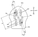
- FIG. 6 is a plan cross-sectional view for explaining the shearing force WK applied to the alternately separating portions 59B when the puller 59 is erected vertically with respect to the slider 50 and twisted clockwise.
- FIG. 7 is a plan sectional view for explaining a state in which the alternately separated portions 59B are broken in the state shown in FIG. 6 and the handle 59 is twisted clockwise.
- FIG. 8 is a plan sectional view for explaining a state in which the handle 59 is twisted until the handle 59 can be removed from the slider body 50A.
- FIG. 6 to 8 are plan sectional views in which the slider main body 50A is cut at the center part of the front pillar part 56F and the rear pillar part 56R.
- interval n is shown.
- the same members as those described in FIG. 1 are denoted by the same reference numerals, and the description thereof is omitted.
- k + m n
- k is an action point distance between the alternate separation portions 59B and the fulcrum 56P
- m is a power point distance from the fulcrum 56P to the center of the arm portion 59A.
- the shearing force WK is larger than the force W when twisting the puller 59, so that the alternating separation part 59B is applied, and the alternating separation part 59B can be broken with a relatively weak operating force. it can.
- the allowable shear stress when fracture occurs is about 265 (MPa).
- the outer diameter of the alternately separated portions 59B is set to 0.3 (mm) to 0.4 (mm)
- the cross-sectional area of the alternately separated portions 59B is 0.071 (mm 2 ) to 0.126 (mm 2 ).
- WK 18.7 (N) to 33.3 (N).
- the alternating separation portions 59B can be easily broken by lightly twisting the handle 59. Can be made.
- the handle 59 was actually made of a zinc alloy, the alternating separation portions 59B could be extremely easily broken.
- the outer diameter of the alternately separated portions 59B is set to 0.3 (mm) to 0.4 (mm) as described above, the slider 50 is slid by applying a sliding force of about 15 (kgf). Even if it was made to make it, the sign which the alternating separation part 59B fracture
- the knob of the handle 59 is rotated to the position of the handle removal position 59T.
- the twisting shaft portion 59K follows the side walls of the front column portion 56F and the rear column portion 56R due to twisting and bending that occur in the arm portion 59A (see FIG. 6).
- the twist angle of the arm portion 59A is ⁇ a
- the deflection amount of the arm portion 59A is Va.
- the tensile stress applied to the arm portion 59A in the case of the arm deflection amount Va is ⁇ a
- the shear stress applied to the arm portion 59A in the case of the arm torsion angle ⁇ a is ⁇ a
- the tensile stress ⁇ a and the shear stress ⁇ a are as follows: It can be calculated by a formula. It is assumed that the cross-sectional shape of the arm portion 59A is a circle having a diameter d, and the length of the arm portion 59A is l.
- ⁇ a tensile stress applied to the arm (MPa)
- Va Arm deflection amount (mm)
- E Longitudinal elastic modulus (GPa) of handle material
- d Diameter of arm part and arm part width
- l Length of arm (mm)
- ⁇ a Shear stress applied to the arm (MPa)
- ⁇ a Arm twist angle (rad)
- G Shear elastic modulus (GPa) of the handle material
- rad Shear elastic modulus
- an allowable arm twist angle ⁇ a is calculated using the above (formula 11).
- the angle ⁇ a ⁇ 0.3 (rad) is calculated.
- the arm twisting angle ⁇ a corresponds to 17.3 (deg).
- the distance between the left and right pulling shaft portions 59K is 2 ⁇ Va ⁇ Cos ⁇ a. It will only open up to about 0.57 (mm).
- the column width Z is generally set to a dimension of about 2.5 (mm), so that the interval between the pulling shaft portions 59K depends on only the deflection of the arm portion 59A than the column width Z. If one tries to spread it, either of the arm parts 59A will always break, and the broken pieces will be separated by this breakage.
- the handle 59 can be detached from the slider body 50A without breaking the arm portion 59A of the handle 59.
- FIG. 9 shows an external perspective view of the handle 59 removed from the slider body 50A.
- the arm interval n is set wider than that of the conventional pull 59, so that even when the alternately separated portions 59B are separated, the arm portions 59A are broken. It is possible to reduce defects that occur.
- the opening amount of the left and right arm portions 59A can be increased. Also, the opening amount of the left and right arm portions 59A can be increased by setting the arm portion width d small.
- both of them are likely to reduce the strength required when operating the handle 59, it is difficult to employ them in applications where it is necessary to perform a sliding operation with a strong force on the slider 50. .
- the arm portion interval n is not related to the strength of the handle 59, it can be set to a relatively large value within a range that does not hinder the sliding operation.
- the arm overhang n 59 is formed at both ends of the pulling shaft 59K in order to prevent the adverse effects caused by setting the arm n n wide and the arm n n wide.
- Alternate opening portions 59B are formed at the center of the handle shaft portion 59K.
- the tensile stress and the shear stress applied to the left and right arm portions 59A when the puller 59 is twisted can be made closer to symmetry.
- the alternately separated portions 59B are separated and the handle is removed from the slider body, it is possible to reduce a problem that a large stress is applied to the one arm portion 59A and breakage occurs.
- FIG. 10 is a plan sectional view for explaining a case where the handle 59p is twisted from the slider body 50A to the handle removal position 59Tp where the handle 59p can be removed.
- FIG. As for the pull handle 59p a cross section cut at an arm portion with an arm portion interval np is shown. The same members as those described in FIG. 1 are denoted by the same reference numerals, and the description thereof is omitted.
- the arm deflection amount Vp and the arm twist angle ⁇ p are smaller than those shown in FIG.
- the stress applied to the arm part of the pulling handle 59p exceeds the allowable stress for fracture. And a fracture
- FIG. 11 shows a state in which the arm portion of the handle 59p is broken.
- the arm portion of the pull handle 59p is broken near the base of the arm portion due to a tensile stress due to bending or a shearing stress due to torsion.
- FIG. 12 is a view showing an embodiment in which a notch 59R is formed on the opposite side of the lock overhang 59H of the pull handle 159 in order to reduce the cross-sectional area increased due to the presence of the lock overhang 59H.
- FIG. 13 is a view showing an embodiment in which the left and right handle shaft portions 59K in the handle 259 are not connected to each other and the non-connecting portion 59S is formed.
- the cross-sectional area increased due to the presence of the locking overhang 59H can be reduced.
- the latch overhang portion 59H is also likely to bend.
- the opening amount between the left and right handle shaft portions 59K can be increased.
- a gap may be formed between the left and right handle shaft portions 59K of the handle 259.
- a non-connecting portion 59S can be formed between the left and right pulling shaft portions 59K.
- the slide fastener using the slider according to the present invention can be used for closing a seat cover of a seat for an automobile, as well as for closing a cover material in an armrest, opening and closing in clothing, shoes, bags, tents and other articles.
- a die casting zinc alloy is used as the material for the handle.
- the present invention is not limited to this zinc alloy, and white copper, brass, and other metals are used.
- synthetic resins can also be used.
Landscapes
- Slide Fasteners (AREA)
- Percussive Tools And Related Accessories (AREA)
- Containers Opened By Tearing Frangible Portions (AREA)
Priority Applications (6)
| Application Number | Priority Date | Filing Date | Title |
|---|---|---|---|
| EP09841117.6A EP2404521B1 (en) | 2009-03-06 | 2009-03-06 | Slider for slide fastener |
| JP2011502555A JP5301651B2 (ja) | 2009-03-06 | 2009-03-06 | スライドファスナー用スライダー |
| PCT/JP2009/054301 WO2010100755A1 (ja) | 2009-03-06 | 2009-03-06 | スライドファスナー用スライダー |
| ES09841117.6T ES2498743T3 (es) | 2009-03-06 | 2009-03-06 | Cursor para cierre de cremallera |
| CN200980157850.XA CN102341011B (zh) | 2009-03-06 | 2009-03-06 | 拉链用拉头 |
| TW098124469A TW201032746A (en) | 2009-03-06 | 2009-07-20 | Slider for slide fastener |
Applications Claiming Priority (1)
| Application Number | Priority Date | Filing Date | Title |
|---|---|---|---|
| PCT/JP2009/054301 WO2010100755A1 (ja) | 2009-03-06 | 2009-03-06 | スライドファスナー用スライダー |
Publications (1)
| Publication Number | Publication Date |
|---|---|
| WO2010100755A1 true WO2010100755A1 (ja) | 2010-09-10 |
Family
ID=42709333
Family Applications (1)
| Application Number | Title | Priority Date | Filing Date |
|---|---|---|---|
| PCT/JP2009/054301 Ceased WO2010100755A1 (ja) | 2009-03-06 | 2009-03-06 | スライドファスナー用スライダー |
Country Status (6)
| Country | Link |
|---|---|
| EP (1) | EP2404521B1 (cg-RX-API-DMAC7.html) |
| JP (1) | JP5301651B2 (cg-RX-API-DMAC7.html) |
| CN (1) | CN102341011B (cg-RX-API-DMAC7.html) |
| ES (1) | ES2498743T3 (cg-RX-API-DMAC7.html) |
| TW (1) | TW201032746A (cg-RX-API-DMAC7.html) |
| WO (1) | WO2010100755A1 (cg-RX-API-DMAC7.html) |
Families Citing this family (1)
| Publication number | Priority date | Publication date | Assignee | Title |
|---|---|---|---|---|
| EP3324776A4 (en) | 2015-07-21 | 2019-04-17 | Travel Caddy, Inc. | INTERLOCKING ZIPPER LOADS AND FASTENING SYSTEM |
Citations (4)
| Publication number | Priority date | Publication date | Assignee | Title |
|---|---|---|---|---|
| JPS60120612U (ja) * | 1984-01-23 | 1985-08-14 | 福島 栄一 | スライドフアスナ−の引手 |
| JPS6443706A (en) | 1987-08-12 | 1989-02-16 | Hitachi Ltd | Straight line detection system for image data |
| JPH0755161A (ja) | 1993-08-10 | 1995-03-03 | Matsushita Electric Ind Co Ltd | 加熱調理器 |
| US6560829B1 (en) * | 2002-02-11 | 2003-05-13 | Shou Mao Chen | Pull tab of a zipper |
Family Cites Families (4)
| Publication number | Priority date | Publication date | Assignee | Title |
|---|---|---|---|---|
| US2280999A (en) * | 1940-03-16 | 1942-04-28 | Talon Inc | Detachable pull tab for slide fastener sliders |
| US2280968A (en) * | 1941-08-15 | 1942-04-28 | Talon Inc | Automatic lock slider for slide fasteners |
| JPS6443706U (cg-RX-API-DMAC7.html) * | 1987-09-10 | 1989-03-15 | ||
| JPH0755161B2 (ja) * | 1989-03-31 | 1995-06-14 | ワイケイケイ株式会社 | 自動停止装置付きスライドファスナー用スライダーの仮引手 |
-
2009
- 2009-03-06 CN CN200980157850.XA patent/CN102341011B/zh not_active Expired - Fee Related
- 2009-03-06 JP JP2011502555A patent/JP5301651B2/ja not_active Expired - Fee Related
- 2009-03-06 WO PCT/JP2009/054301 patent/WO2010100755A1/ja not_active Ceased
- 2009-03-06 EP EP09841117.6A patent/EP2404521B1/en not_active Not-in-force
- 2009-03-06 ES ES09841117.6T patent/ES2498743T3/es active Active
- 2009-07-20 TW TW098124469A patent/TW201032746A/zh not_active IP Right Cessation
Patent Citations (4)
| Publication number | Priority date | Publication date | Assignee | Title |
|---|---|---|---|---|
| JPS60120612U (ja) * | 1984-01-23 | 1985-08-14 | 福島 栄一 | スライドフアスナ−の引手 |
| JPS6443706A (en) | 1987-08-12 | 1989-02-16 | Hitachi Ltd | Straight line detection system for image data |
| JPH0755161A (ja) | 1993-08-10 | 1995-03-03 | Matsushita Electric Ind Co Ltd | 加熱調理器 |
| US6560829B1 (en) * | 2002-02-11 | 2003-05-13 | Shou Mao Chen | Pull tab of a zipper |
Non-Patent Citations (1)
| Title |
|---|
| See also references of EP2404521A4 * |
Also Published As
| Publication number | Publication date |
|---|---|
| EP2404521A4 (en) | 2013-03-20 |
| TWI379649B (cg-RX-API-DMAC7.html) | 2012-12-21 |
| CN102341011B (zh) | 2015-03-11 |
| CN102341011A (zh) | 2012-02-01 |
| ES2498743T3 (es) | 2014-09-25 |
| TW201032746A (en) | 2010-09-16 |
| EP2404521A1 (en) | 2012-01-11 |
| JP5301651B2 (ja) | 2013-09-25 |
| EP2404521B1 (en) | 2014-08-06 |
| JPWO2010100755A1 (ja) | 2012-09-06 |
Similar Documents
| Publication | Publication Date | Title |
|---|---|---|
| JP4726876B2 (ja) | 逆開きスライドファスナー | |
| CN100528029C (zh) | 用于拉链的滑动件以及拉链 | |
| JP5898680B2 (ja) | スライドファスナー用スライダー | |
| EP1961325B1 (en) | Slider for slide fastener | |
| CN102843928B (zh) | 拉链用拉头 | |
| CN102469858B (zh) | 拉链 | |
| JPWO2008093705A1 (ja) | ハーネスクリップ構造 | |
| KR20100128347A (ko) | 자동 정지 장치가 구비된 슬라이드 파스너용 슬라이더 | |
| WO2010113275A1 (ja) | スライドファスナー用スライダー並びにクイックオープン式スライドファスナー | |
| WO2010113281A1 (ja) | 開離嵌挿具付スライドファスナー | |
| JP5301651B2 (ja) | スライドファスナー用スライダー | |
| TW201212839A (en) | Slider for slide fasteners | |
| WO2011016123A1 (ja) | スライドファスナー | |
| EP2848150B1 (en) | Slider for slide fastener | |
| WO2012140780A1 (ja) | スライドファスナー用スライダー | |
| WO2012090276A1 (ja) | 開離嵌挿具付きスライドファスナー | |
| JP2013031691A (ja) | スライドファスナー用スライダー | |
| CN104023582B (zh) | 拉链用拉片 | |
| CN103763969B (zh) | 拉链用拉头 | |
| TW201029594A (en) | Fastener element for concealed slide fasteners | |
| US8108974B2 (en) | Closure for joining at least two pieces of material | |
| TWI531331B (zh) | Slider | |
| TWI484925B (zh) | Zipper slide, slider body, zipper slide with the manufacturing method and zipper | |
| JP2013006083A (ja) | スライドファスナー用スライダー | |
| JP2009033870A (ja) | ロック構造およびロック構造を備えたワイヤハーネス用のプロテクタ |
Legal Events
| Date | Code | Title | Description |
|---|---|---|---|
| WWE | Wipo information: entry into national phase |
Ref document number: 200980157850.X Country of ref document: CN |
|
| 121 | Ep: the epo has been informed by wipo that ep was designated in this application |
Ref document number: 09841117 Country of ref document: EP Kind code of ref document: A1 |
|
| ENP | Entry into the national phase |
Ref document number: 2011502555 Country of ref document: JP Kind code of ref document: A |
|
| WWE | Wipo information: entry into national phase |
Ref document number: 2009841117 Country of ref document: EP |
|
| NENP | Non-entry into the national phase |
Ref country code: DE |