WO2010098203A1 - 通信装置及び通信方法、コンピューター・プログラム、並びに通信システム - Google Patents
通信装置及び通信方法、コンピューター・プログラム、並びに通信システム Download PDFInfo
- Publication number
- WO2010098203A1 WO2010098203A1 PCT/JP2010/051898 JP2010051898W WO2010098203A1 WO 2010098203 A1 WO2010098203 A1 WO 2010098203A1 JP 2010051898 W JP2010051898 W JP 2010051898W WO 2010098203 A1 WO2010098203 A1 WO 2010098203A1
- Authority
- WO
- WIPO (PCT)
- Prior art keywords
- communication
- wireless communication
- communication method
- transmission
- frame
- Prior art date
Links
Images


Classifications
-
- H—ELECTRICITY
- H04—ELECTRIC COMMUNICATION TECHNIQUE
- H04B—TRANSMISSION
- H04B7/00—Radio transmission systems, i.e. using radiation field
- H04B7/02—Diversity systems; Multi-antenna system, i.e. transmission or reception using multiple antennas
- H04B7/04—Diversity systems; Multi-antenna system, i.e. transmission or reception using multiple antennas using two or more spaced independent antennas
- H04B7/06—Diversity systems; Multi-antenna system, i.e. transmission or reception using multiple antennas using two or more spaced independent antennas at the transmitting station
- H04B7/0613—Diversity systems; Multi-antenna system, i.e. transmission or reception using multiple antennas using two or more spaced independent antennas at the transmitting station using simultaneous transmission
- H04B7/0615—Diversity systems; Multi-antenna system, i.e. transmission or reception using multiple antennas using two or more spaced independent antennas at the transmitting station using simultaneous transmission of weighted versions of same signal
- H04B7/0617—Diversity systems; Multi-antenna system, i.e. transmission or reception using multiple antennas using two or more spaced independent antennas at the transmitting station using simultaneous transmission of weighted versions of same signal for beam forming
-
- H—ELECTRICITY
- H04—ELECTRIC COMMUNICATION TECHNIQUE
- H04B—TRANSMISSION
- H04B7/00—Radio transmission systems, i.e. using radiation field
- H04B7/02—Diversity systems; Multi-antenna system, i.e. transmission or reception using multiple antennas
- H04B7/04—Diversity systems; Multi-antenna system, i.e. transmission or reception using multiple antennas using two or more spaced independent antennas
- H04B7/08—Diversity systems; Multi-antenna system, i.e. transmission or reception using multiple antennas using two or more spaced independent antennas at the receiving station
- H04B7/0837—Diversity systems; Multi-antenna system, i.e. transmission or reception using multiple antennas using two or more spaced independent antennas at the receiving station using pre-detection combining
- H04B7/0842—Weighted combining
- H04B7/0848—Joint weighting
-
- H—ELECTRICITY
- H04—ELECTRIC COMMUNICATION TECHNIQUE
- H04B—TRANSMISSION
- H04B7/00—Radio transmission systems, i.e. using radiation field
- H04B7/02—Diversity systems; Multi-antenna system, i.e. transmission or reception using multiple antennas
- H04B7/04—Diversity systems; Multi-antenna system, i.e. transmission or reception using multiple antennas using two or more spaced independent antennas
- H04B7/08—Diversity systems; Multi-antenna system, i.e. transmission or reception using multiple antennas using two or more spaced independent antennas at the receiving station
- H04B7/0837—Diversity systems; Multi-antenna system, i.e. transmission or reception using multiple antennas using two or more spaced independent antennas at the receiving station using pre-detection combining
- H04B7/0842—Weighted combining
- H04B7/0865—Independent weighting, i.e. weights based on own antenna reception parameters
-
- H—ELECTRICITY
- H04—ELECTRIC COMMUNICATION TECHNIQUE
- H04W—WIRELESS COMMUNICATION NETWORKS
- H04W72/00—Local resource management
- H04W72/04—Wireless resource allocation
- H04W72/044—Wireless resource allocation based on the type of the allocated resource
- H04W72/046—Wireless resource allocation based on the type of the allocated resource the resource being in the space domain, e.g. beams
-
- H—ELECTRICITY
- H04—ELECTRIC COMMUNICATION TECHNIQUE
- H04W—WIRELESS COMMUNICATION NETWORKS
- H04W74/00—Wireless channel access, e.g. scheduled or random access
- H04W74/002—Transmission of channel access control information
Definitions
- the present invention relates to a communication apparatus and communication method, a computer program, and a communication system that perform wireless communication using, for example, millimeter waves, and in particular, directs a beam of a directional antenna toward a direction where a communication partner is located.
- the present invention relates to a communication apparatus and communication method for extending a wave communication distance, a computer program, and a communication system.
- millimeter wave can realize high speed communication using high frequency electromagnetic waves.
- Major applications of millimeter wave communication include short-distance wireless access communication, image transmission systems, simple wireless, and automobile collision prevention radar.
- millimeter-wave communication technology is being developed to promote use, such as realization of large-capacity and long-distance transmission, miniaturization and cost reduction of wireless devices.
- the wavelength of the millimeter wave corresponds to 10 mm to 1 mm and the frequency corresponds to 30 GHz to 300 GHz.
- channels can be allocated in units of GHz, so extremely high-speed data communication can be performed.
- Millimeter wave has a short wavelength and strong straightness, and can transmit a very large amount of information even compared to microwaves that are widely used in wireless LAN (Local Area Network) technology and the like.
- LAN Local Area Network
- millimeter waves are strongly attenuated due to reflection, a direct wave or a reflected wave of about one time is mainly used as a wireless path for communication.
- the millimeter wave has a property that a radio signal does not reach far because of a large propagation loss.
- the antenna of the transmitter / receiver has directivity and the transmission beam and the reception beam are directed toward the communication partner to extend the communication distance.
- the directivity of the beam can be controlled by, for example, providing a plurality of antennas for each transceiver and changing the transmission weight or reception weight for each antenna.
- the reflected wave is hardly used, and the direct wave becomes important. Therefore, the directivity of the beam shape is suitable, and it is conceivable to use a sharp beam as the directivity. Then, after learning the optimum directivity of the antenna, millimeter-wave wireless communication may be performed.
- a signal for determining the directivity direction of the transmission antenna is transmitted by the second communication means using communication by any one of power line communication, optical communication, and sound wave communication, and the direction of the transmission antenna is determined.
- a wireless transmission system that performs wireless transmission between the transmitter and the receiver by the first communication means using radio waves of 10 GHz or more has been proposed (for example, see Patent Document 1).
- a method for extending the communication distance using the antenna directivity is also applied to IEEE802.15.3c, which is a standard of a wireless PAN (mmWPAN: millimeter-wave wireless area network) that uses a millimeter wave band. ing.
- IEEE802.15.3c is a standard of a wireless PAN (mmWPAN: millimeter-wave wireless area network) that uses a millimeter wave band. ing.
- the millimeter wave signal is not transmitted to the peripheral station that is not in that direction. Has the negative effect of not reaching.
- directional communication is not appropriate when transmitting a control frame such as a beacon to a control signal simultaneously to a plurality of communication stations.
- the communication link is easily invalidated as the communication station moves, and there is a possibility that a desired communication cannot be performed.
- position information acquisition means such as a GPS (Global Positioning System) unit, acquires position information of its own device, exchanges position information with the communication partner, and controls the directivity of the directional antenna.
- a wireless terminal device that performs long-distance data transmission using millimeter waves has been proposed (for example, see Patent Document 2). According to the wireless terminal device, even if the positional relationship with the communication partner fluctuates, it is possible to escape from a situation where communication is not possible by exchanging position information and adjusting antenna directivity, but position information acquisition means It is necessary to implement a communication procedure for exchanging position information with a communication partner and an increase in apparatus cost associated with the installation.
- the wireless terminal device is configured to transmit data using millimeter wave radio waves having broadband characteristics and transmit control information using microwave band radio waves. You can't coordinate with it.
- An object of the present invention is to provide an excellent communication device, communication method, computer program, and communication system capable of extending the communication distance of millimeter waves by directing a beam of a directional antenna in a direction where a communication partner is located. There is to do.
- a further object of the present invention is to provide an excellent communication apparatus and communication method, computer program, and communication system capable of appropriately coordinating with a plurality of communication partners performing millimeter wave communication or directional communication. There is to do.
- a further object of the present invention is that it is possible to suitably recover a communicable situation even if the communication link of millimeter wave communication or directional communication becomes invalid due to fluctuations in the positional relationship with the communication partner, etc.
- a communication apparatus and method, a computer program, and a communication system are provided.
- the present application has been made in consideration of the above-described problems, and the invention according to claim 1 includes a first wireless communication unit that performs wireless communication according to a first communication method, A second wireless communication unit capable of performing directional wireless communication according to a second communication method using a higher frequency band than the first communication method; With The communication apparatus transmits a control frame including control information for coordinating with one or more communication partners performing wireless communication according to the second communication method from the first wireless communication unit.
- control information information on the capability of wireless communication according to the second communication method by the second wireless communication unit, the second Information on a channel used in wireless communication according to the second communication method by the wireless communication unit, and a transmission beam formed when wireless communication according to the second communication method is performed by the second wireless communication unit
- the information regarding a receiving beam and the information regarding the timing which the said communication other party allocates to the said communication other party, and starts a transmission operation according to a said 2nd communication system can be included.
- the communication device is for confirming the effectiveness of the communication link according to the second communication method with respect to the communication partner.
- a frame including information designating a timing at which the communication partner should transmit a link maintenance frame is transmitted from the first wireless communication unit according to the first communication method, and at the transmission timing, the second The wireless communication unit is configured to wait for reception of a link maintenance frame according to the second communication method.
- control information includes information related to timing at which the communication partner starts transmission operation according to the second communication method, which is assigned to the communication partner.
- the communication apparatus according to claim 6 is configured to receive and process an RTS transmitted by the communication partner according to the second communication method in accordance with the transmission start timing as the link maintenance frame.
- the one or more communication partners are Rescheduling the timing at which the link maintenance frame should be transmitted, and transmitting the reschedule frame including information on the rescheduled transmission timing from the first wireless communication unit according to the first communication method It is configured.
- the communication apparatus transmits a training request frame for requesting re-learning of directivity of transmission / reception beams from the communication partner according to the first communication method.
- a training request response frame is returned in accordance with the first communication method, and a re-learning process of directivity between the communication partner and the transmission / reception beam is performed.
- the invention according to claim 10 of the present application is the first communication unit that performs wireless communication according to the first communication method, and the second communication method that uses a higher frequency band than the first communication method.
- the invention according to claim 11 of the present application is A first wireless communication unit that performs wireless communication according to a first communication method; A second wireless communication unit capable of performing directional wireless communication according to a second communication method using a higher frequency band than the first communication method; With The communication apparatus receives a control frame including control information for coordinating with one or more communication partners that perform wireless communication according to the second communication method, in the first wireless communication unit.
- control information includes information related to a timing at which the control information is started by the communication partner according to the second communication method.
- 11 is configured to start a transmission operation according to the second communication method by the second wireless communication unit according to the transmission start timing.
- the communication device of claim 11 is a link for confirming the validity of the communication link according to the second communication method from the communication partner.
- a frame including information designating a timing for transmitting a maintenance frame to the communication partner is received by the first wireless communication unit according to the first communication method, and at the transmission timing, the second The wireless communication unit is configured to transmit a link maintenance frame according to the second communication method.
- control information includes information related to timing at which the control information is started by the communication partner according to the second communication method.
- the communication device according to 13 is configured to transmit an RTS that also serves as the link maintenance frame in accordance with the second communication method in accordance with the transmission start timing.
- the communication apparatus described in claim 13 transmits the RTS according to the second communication method in accordance with a predetermined transmission start timing, and also performs the link maintenance. It is configured to receive and process a CTS that also serves as a frame.
- the communication device can receive the training request frame when the link maintenance frame is not received. Transmitting from the first wireless communication unit according to the first communication method, and in response to receiving a training request response frame from the communication partner according to the first communication method, the communication partner and the directivity of the transmission / reception beam The re-learning process is implemented.
- the communication device transmits a data frame from the second wireless communication unit to the communication partner according to the second communication method.
- the first wireless communication unit is configured to transmit a data frame to the communication partner in accordance with the first communication method.
- the communication device transmits a data frame from the second wireless communication unit to the communication partner according to the second communication method.
- the data frame is transmitted from the first wireless communication unit to the communication partner in accordance with the first communication method at a timing independent from the transmission.
- a first wireless communication unit that performs wireless communication according to the first communication method, and a second communication method that uses a higher frequency band than the first communication method.
- a communication method in a communication device including a second wireless communication unit capable of performing directional wireless communication according to The communication method includes a step of receiving, by the first wireless communication unit, a control frame including control information for coordinating with one or more communication partners that perform wireless communication according to the second communication method.
- the invention according to claim 20 of the present application is the first wireless communication unit that performs wireless communication according to the first communication method, and the second communication method that uses a higher frequency band than the first communication method.
- the invention according to claim 21 of the present application is the first wireless communication unit that performs wireless communication according to the first communication method, and the second communication method that uses a higher frequency band than the first communication method.
- Each computer program according to claims 20 and 21 of the present application defines a computer program described in a computer-readable format so as to realize predetermined processing on a computer.
- a cooperative action is exhibited on the computer, and is the same as each communication device according to claims 1 and 11 of the present application. The effects of each can be obtained.
- the invention according to claim 22 of the present application is the first wireless communication unit that performs wireless communication according to the first communication method, and the second communication method that uses a higher frequency band than the first communication method.
- a control frame including control information for coordinating with one or more communication partners that perform wireless communication according to the second communication method.
- a first communication device that transmits from the first wireless communication unit;
- a first wireless communication unit that performs wireless communication according to the first communication method, and a second wireless communication that can perform directional wireless communication according to a second communication method that uses a higher frequency band than the first communication method.
- a second communication device that receives the control frame at the first wireless communication unit as a communication partner to the first communication device;
- a communication system comprising:
- system here refers to a logical collection of a plurality of devices (or functional modules that realize specific functions), and each device or functional module is in a single housing. It does not matter whether or not.
- an excellent communication apparatus and communication method, computer program, and communication system that can extend the communication distance of millimeter waves by directing the beam of a directional antenna toward the direction of the communication partner are provided. can do.
- an excellent communication apparatus and communication method, computer program, and communication system capable of appropriately coordinating with a plurality of communication partners performing millimeter wave communication or directional communication are provided. Can be provided.
- a communication apparatus and method, a computer program, and a communication system can be provided.
- the communication device is omnidirectional using, for example, the 5 GHz band and has no flying distance problem.
- High-speed data communication according to the second communication method using millimeter waves can be realized by coordinating with the communication partner using the first communication method as an auxiliary.
- the directional communication link according to the second communication method using millimeter waves becomes invalid due to a change in the positional relationship with the communication partner or the like, the situation in which communication is possible is preferably recovered. be able to.
- the control information described in the control frame such as a beacon includes the beacon transmission source in addition to the information for coordinating in the second communication method.
- a communication device that operates as a coordinator such as an access point, information regarding the capability of wireless communication according to the second communication method, information regarding a channel used in wireless communication according to the second communication method, Additional information such as information regarding a transmission beam or a reception beam formed when performing wireless communication according to the second communication method can be included.
- the first communication method that is omnidirectional and does not have a flight distance problem is used as an auxiliary.
- the timing for transmitting a link maintenance frame for confirming the validity of the communication link according to the second communication method can be determined in advance.
- the communication partner that has not received the link maintenance frame is assumed to be out of the communication range of the second communication method, and is assigned to the communication partner.
- the timing can be released and rescheduled, and as a result, the bandwidth can be used efficiently.
- the first communication method is used in an auxiliary manner with a communication partner that is out of the communication range of the second communication method.
- the directional re-learning can be performed, so that it is possible to suitably recover the communication status with a communication partner whose communication link for millimeter wave communication or directional communication has become invalid due to a change in positional relationship, etc. it can.
- the communication device when the communication device performs data transmission according to the second communication method, the communication device synchronizes with the data transmission according to the first communication method. Can also be performed.
- the communication device can perform data transmission according to the first communication method with scheduling independent of data transmission according to the second communication method. it can.
- FIG. 1 is a diagram schematically showing a configuration example of a millimeter wave radio communication system according to an embodiment of the present invention.
- FIG. 2 is a diagram illustrating a configuration example of the wireless communication device 100.
- FIG. 3 is a diagram illustrating an example of an internal configuration of the first digital unit 130.
- FIG. 4 is a diagram illustrating an example of the internal configuration of the second digital unit 180.
- FIG. 5 is a diagram illustrating an example of a transmission beam pattern that can be formed by the wireless communication device 100 by directivity control of the transmission beam by the transmission beam processing unit 185.
- FIG. 6 is a diagram showing an embodiment in which the present invention is applied to an infrastructure mode wireless communication system.
- FIG. 1 is a diagram schematically showing a configuration example of a millimeter wave radio communication system according to an embodiment of the present invention.
- FIG. 2 is a diagram illustrating a configuration example of the wireless communication device 100.
- FIG. 3 is a diagram illustrating an example of an internal configuration of the first digital
- FIG. 7 is a diagram illustrating BSS operation information at the time of communication according to the second communication method described in the beacon.
- FIG. 8 is a diagram showing an example of a signal transmission / reception sequence performed using the RTS / CTS method in the wireless communication system shown in FIG.
- FIG. 9 is a diagram illustrating an example of a signal format of a beam learning signal used by a communication partner for beam learning.
- FIG. 10 is a diagram showing an example of a signal transmission / reception sequence for performing link maintenance using the RTS / CTS handshake procedure.
- FIG. 11 is a flowchart showing a processing procedure for the access point (AP) to realize the signal transmission / reception sequence shown in FIG.
- FIG. 12 is a flowchart showing a processing procedure for the terminal stations (STA1, STA2) to realize the signal transmission / reception sequence shown in FIG.
- FIG. 13 is a diagram showing another example of a signal transmission / reception sequence for performing link maintenance using the RTS / CTS handshake procedure.
- FIG. 14 is a diagram showing still another example of a signal transmission / reception sequence for performing link maintenance using the RTS / CTS handshake procedure.
- FIG. 15 is a flowchart showing a processing procedure for the data transmission side (RTS transmission side: STA_Tx) to realize the signal transmission / reception sequence shown in FIG.
- FIG. 16 is a flowchart showing a processing procedure for the data reception side (CTS transmission side: STA_Rx) to realize the signal transmission / reception sequence shown in FIG.
- FIG. 17 is a diagram showing a signal transmission / reception sequence example in which link maintenance is performed using a dedicated link maintenance frame.
- FIG. 18 is a flowchart of a processing procedure for the link maintenance frame transmission side to realize the signal transmission / reception sequence shown in FIG.
- FIG. 19 is a flowchart showing a processing procedure for the link maintenance frame receiving side to realize the signal transmission / reception sequence shown in FIG. FIG.
- FIG. 20 shows an example of a signal transmission / reception sequence between an access point (AP) and a terminal station (STA) when scheduling is performed in synchronization with the first and second communication methods and data transmission is performed completely simultaneously. It is a figure.
- FIG. 21 is a diagram illustrating an example of a signal transmission / reception sequence between an access point (AP) and a terminal station (STA) when scheduling is performed independently in each of the first and second communication schemes.
- FIG. 22 is a diagram illustrating a configuration example of an information device on which the modularized wireless communication device 100 is mounted.
- a wireless communication system using millimeter waves uses a plurality of transmission / reception antennas to form a sharp antenna directivity (that is, a beam-shaped antenna directivity).
- the range can be expanded.
- directional communication is not appropriate for transmission of control frames and coordination is not possible, and fluctuations in the positional relationship with the communication partner As a result, there is a concern that once the communication link becomes invalid, communication cannot be performed as it is.
- a directional communication system using a microwave (5 GHz band) defined by IEEE 802.11 scheduling within a frame period is performed by transmitting a coordination frame at a communication rate lower than that at the time of data transmission.
- a coordination frame is transmitted to peripheral stations to ensure more secure coordination.
- millimeter waves there is a possibility that the signal does not reach the peripheral station sufficiently even if the communication rate is lowered.
- the wireless communication system uses 5 GHz band wireless communication in combination with 60 GHz band wireless communication, and supplements the 5 GHz band for transmission of control information for coordination in 60 GHz band communication such as a beacon. For this reason, the control information reaches the peripheral station sufficiently.
- the first communication method using microwaves is not strong in straight line as compared with millimeter waves and has a small attenuation at the time of reflection. Therefore, the first communication method can communicate with each other without considering the directivity of the transmission beam and the reception beam. it can.
- the second communication method since the second communication method uses millimeter waves, it is preferable to transmit / receive a radio signal with the transmission beam and the reception beam directed to the communication partner because the linearity is strong and the attenuation at the time of reflection is large. .
- the first communication method is a communication method using microwave electromagnetic waves (5 GHz band) used in IEEE802.11a / b / g, which is widely used as a wireless LAN standard
- the communication method 2 is assumed to be a 60 GHz band used in the VHT (Very High Throughput) standard.
- VHT Very High Throughput
- the gist of the present invention is that the first and second communication methods are not necessarily limited to a specific frequency band.
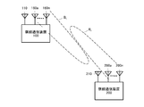
- FIG. 1 schematically shows a configuration example of a millimeter wave radio communication system according to an embodiment of the present invention.
- the illustrated wireless communication system includes a wireless communication device 100 and a wireless communication device 200.
- the wireless communication devices 100 and 200 can wirelessly communicate with each other using both the first communication method and the second communication method described above.
- the first communication system that uses microwaves is not as straight as compared to millimeter waves, and has little attenuation during reflection. Therefore, when the wireless communication apparatuses 100 and 200 perform wireless communication according to the first communication method, they can communicate with each other without considering the directivity of the transmission beam and the reception beam.
- the second communication method uses millimeter waves, the straight communication property is strong and the attenuation at the time of reflection is large.
- the wireless communication device 100 includes an antenna 110 for transmitting and receiving wireless signals according to the first communication method and a plurality of antennas 160a to 160n for transmitting and receiving wireless signals according to the second communication method. I have. Then, by adjusting the weights of the signals transmitted via antennas 160a ⁇ 160n, and controls the directivity B t transmit beam during a wireless communication in accordance with the second communication method. In the illustrated example, the transmission beam B t is directed in the direction of the position of the wireless communication device 200 that is the communication partner.
- the wireless communication apparatus 200 includes an antenna 210 for transmitting / receiving a wireless signal according to the first communication method and a plurality of antennas 260a to 260n for transmitting / receiving a wireless signal according to the second communication method. Then, by adjusting the weights of signals received via antennas 260a ⁇ 260n, and controls the directivity B r of the received beam at the time of radio communication in accordance with the second communication method.
- the reception beam Br is directed in the direction of the position of the wireless communication device 100 serving as a communication partner.
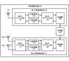
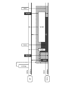
- FIG. 2 shows a configuration example of the wireless communication device 100.
- the illustrated wireless communication apparatus 100 may operate as a broadband router or a wireless access point. Although not shown, the wireless communication apparatus 200 may have the same configuration.
- the wireless communication device 100 includes an antenna 110, a first wireless communication unit 120, a storage unit 150, a plurality of antennas 160a to 160n, and a second wireless communication unit 170.
- the first wireless communication unit 120 includes a first analog unit 122, an AD (Analog-to-Digital) conversion unit 124, a DA (Digital-to-Analog) conversion unit 126, and a first digital unit 130.
- the control unit 140 is configured.
- the second wireless communication unit 170 includes a second analog unit 172, an AD conversion unit 174, a DA conversion unit 176, a second digital unit 180, and a control unit 190.
- the antenna 110 is an antenna used for wireless communication according to the first communication method.
- the antenna 110 transmits, for example, a control signal for coordinating in the second communication method such as a beacon according to the first communication method using microwaves. Further, the antenna 110 receives a control signal for coordinating in the second communication method such as a beacon in accordance with the first communication method, and outputs the control signal to the first analog unit 122.
- the first analog unit 122 typically corresponds to an RF (Radio Frequency) circuit for transmitting and receiving a radio signal according to the first communication method.
- the first analog unit 122 amplifies the RF reception signal received by the antenna 110 with low noise, down-converts it, and outputs it to the AD conversion unit 124 at the subsequent stage.
- the first analog unit 122 also up-converts the transmission signal converted into the analog signal by the DA conversion unit 126 into the RF band, amplifies the power, and outputs the amplified signal to the antenna 110.
- the AD conversion unit 124 converts the analog reception signal input from the first analog unit 122 into a digital signal and outputs the digital signal to the first digital unit 130 at the subsequent stage. Further, the DA conversion unit 126 converts the digital transmission signal input from the first digital unit 130 into an analog signal and outputs the analog signal to the first analog unit 122.
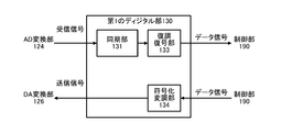
- FIG. 3 shows an example of the internal configuration of the first digital unit 130.
- the first digital unit 130 includes a synchronization unit 131, a demodulation / decoding unit 132, and a coded modulation unit 133.
- the synchronization unit 131 synchronizes the reception processing start timing with respect to the reception signal of the antenna 110 in accordance with the detection of the first preamble of the frame of the first communication method.
- the demodulation / decoding unit 132 demodulates and decodes the received signal according to an arbitrary modulation method and coding method used for the first communication method, acquires a data signal, and outputs the data signal to the control unit 140.
- the encoding modulation unit 133 encodes and modulates the data signal input from the control unit 140 according to an arbitrary encoding method and modulation method used for the first communication method, generates a transmission signal, and generates a DA.
- the data is output to the conversion unit 126.
- the control unit 140 is configured using an arithmetic device such as a microprocessor, for example, and controls the overall operation of the first wireless communication unit 120. For example, the control unit 140 sends a control signal for coordinating in the second communication system such as a beacon to the first digital unit 130 in response to a request from a predetermined application (such as an upper layer program of a communication protocol). Output. In addition, when a decoded control signal is input from the first digital unit 130, the control unit 140 acquires information related to coordination in the second communication method described in the control signal, and stores the information. Stored in the unit 150 as appropriate.
- a control signal for coordinating in the second communication system such as a beacon
- a predetermined application such as an upper layer program of a communication protocol
- the storage unit 150 is configured by a writable recording medium such as a semiconductor memory, for example, and loads a program for executing communication processing by the wireless communication apparatus 100 or stores various parameter values as a work memory. Used. In addition, the storage unit 150 stores parameter values for specifying an optimal transmission / reception beam pattern for the wireless communication by the second wireless communication unit 170 according to the second communication method.
- a writable recording medium such as a semiconductor memory
- the plurality of antennas 160a to 160n are used for wireless communication according to the second communication method. Specifically, antennas 160a to 160n transmit radio signals weighted using a predetermined weighting factor using millimeter waves, respectively. Further, the antennas 160 a to 160 n receive millimeter wave radio signals and output them to the second analog unit 172.
- the second analog unit 172 typically corresponds to an RF circuit for transmitting and receiving a radio signal according to the second communication method. That is, the second analog unit 172 performs low-noise amplification and down-conversion on the plurality of received signals respectively received by the antennas 160a to 160n, and outputs them to the AD conversion unit 174 at the subsequent stage. The second analog unit 172 up-converts the plurality of transmission signals converted into analog signals by the DA conversion unit 176 to the RF band, amplifies the power, and outputs the amplified signals to the antennas 160a to 160n.
- the AD conversion unit 174 converts each of the plurality of analog reception signals input from the second analog unit 172 into a digital signal and outputs the digital signal to the second digital unit 180 at the subsequent stage. Further, the DA conversion unit 176 converts each of the plurality of digital transmission signals input from the second digital unit 180 into analog signals and outputs the analog signals to the second analog unit 172.
- the second digital unit 180 is typically a circuit for demodulating and decoding a received signal according to the second communication scheme, and a circuit for encoding and modulating a transmission signal according to the second communication scheme. Composed.
- FIG. 4 shows an example of the internal configuration of the second digital unit 180.
- the second digital unit 180 includes a synchronization unit 181, a reception beam processing unit 182, a power calculation unit 183, a determination unit 184, a demodulation decoding unit 185, a coded modulation unit 186, a transmission
- the beam processing unit 187 is configured.
- the synchronization unit 181 synchronizes the reception processing start timing according to the preamble at the beginning of the frame for the plurality of reception signals received by the plurality of antennas 160a to 160n and outputs the received signal to the reception beam processing unit 182.
- the reception beam processing unit 182 controls the directivity of the reception beam by weighting the plurality of reception signals input from the synchronization unit 181 according to, for example, a uniform distribution or a Taylor distribution. Reception beam processing section 182 then outputs the weighted reception signal to power calculation section 183 and demodulation decoding section 185.
- the power calculation unit 183 calculates reception power of reception signals transmitted / received by each transmission / reception beam pattern, and sequentially outputs them to the determination unit 184. Then, the determination unit 184 determines an optimal transmission beam pattern and a parameter value for specifying the reception beam pattern based on the reception power value input from the power calculation unit 183.
- the optimum beam pattern is typically a beam pattern in which a series of received power values input from the power calculation unit 183 with respect to one beam learning signal is a maximum value.
- the demodulation / decoding unit 185 demodulates and decodes the reception signal weighted by the reception beam processing unit 182 according to an arbitrary modulation method and encoding method used for the second communication method, and obtains a data signal. Then, the demodulation / decoding unit 185 outputs the acquired data signal to the control unit 190.
- the encoding modulation unit 186 encodes and modulates the data signal input from the control unit 190 in accordance with an arbitrary encoding method and modulation method used for the second communication method, and generates a transmission signal. Then, the encoding modulation unit 186 outputs the generated transmission signal to the transmission beam processing unit 187.
- the transmission beam processing unit 187 generates a plurality of transmission signals weighted according to, for example, uniform distribution or Taylor distribution from the transmission signal input from the encoding modulation unit 186, and controls the directivity of the transmission beam.
- the value of the weight used by the transmission beam processing unit 187 is specified by a directivity control signal input from the control unit 190, for example.
- the plurality of transmission signals weighted by the transmission beam processing unit 187 are output to the DA conversion unit 176, respectively.
- the control unit 190 is configured using an arithmetic device such as a microprocessor, for example, and controls the overall operation of the second wireless communication unit 170. Further, the control unit 190 acquires a parameter value for specifying an optimal transmission beam pattern from the storage unit 150, and directivity for forming an optimal transmission beam pattern specified based on the parameter value. The control signal is output to the transmission beam processing unit 187 in the second digital unit 180. Thereby, the transmission beam at the time of wireless transmission according to the second communication method by the wireless communication device 100 is directed to the direction in which the communication partner is located.
- an arithmetic device such as a microprocessor
- FIG. 5 shows an example of a transmission beam pattern that can be formed by the wireless communication apparatus 100 by directivity control of the transmission beam by the transmission beam processing unit 187.
- the wireless communication apparatus 100 can form ten transmission beam patterns B t0 to B t9 .
- the transmission beam patterns B t0 to B t9 have directivities in different directions by 36 degrees on the plane where the radio communication apparatus 100 is located.
- the transmission beam processing unit 187 uses any one of the ten transmission beam patterns B t0 to B t9 to transmit directivity. Wireless signals can be transmitted from the antennas 160a to 160n.
- the reception beam pattern that can be formed by the wireless communication apparatus 100 may be the same beam pattern as the transmission beams B t0 to B t9 shown in FIG. That is, the reception beam processing unit 182 matches any one (or a combination of two or more) of the ten reception beam patterns B r0 to B r9 according to the directivity control signal from the control unit 190.
- radio signals according to the second communication method can be received by the antennas 160a to 160n.
- weighting factors for the antennas 160a to 160n for forming these transmission / reception beam patterns B t0 to B t9 and B r0 to B r9 are stored in advance.
- the transmission beam pattern and the reception beam pattern that can be formed by the wireless communication apparatus 100 are not limited to the example shown in FIG.
- the plurality of antennas 160a to 160n can be configured so as to form a transmission beam pattern or a reception beam pattern having directivity in various directions in a three-dimensional space.
- the wireless communication apparatus 100 uses a first wireless communication unit 120 that performs wireless communication using microwaves and a second wireless communication unit 170 that performs wireless communication using millimeter waves. Specifically, a control signal for taking coordination in the second communication method such as a beacon is transmitted and received by the first wireless communication unit 120 and the antenna 110, and after the coordination is taken, the second wireless communication unit 170 is transmitted. In addition, transmission / reception is performed by a plurality of antennas 160a to 160n.
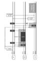
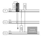
- the illustrated communication system is an infrastructure network composed of one access point (AP) and two terminal stations (STA1, STA2). These three communication stations (AP, STA1, STA2) are all configured using the wireless communication device 100 shown in FIG.
- the transmission / reception beams of the second wireless communication unit 170 of each terminal station (STA1, STA2) are all directed to the access point (AP) side, and each terminal station (STA1, STA2) accesses
- a communication link is established with the point (AP) by the second communication method, and can be used as a link for high-speed data transmission between the access point (AP) and each terminal station (STA1, STA2).
- the communication link by the 1st communication system between an access point (AP) and each terminal station (STA1, STA2) is effective, and can be utilized as a link for coordination.
- the communication link according to the second communication method is invalid, in other words, for high-speed data transmission between the terminal stations STA1 and STA2.
- the link has not been established.
- the communication link by the first communication method between the terminal stations STA1 and STA2 is effective, and can be supplementarily used as a communication link for coordination.
- the access point (AP) periodically transmits a beacon that describes operation information of a basic service set (BSS) to which the station belongs, according to the first communication method.
- a cycle for transmitting a beacon is referred to as a “frame cycle”.
- the beacon is a control signal for coordinating with each terminal station (STA1, STA2).
- the beacon transmitted according to the first communication method includes the BSS operation information during communication according to the first communication method and the BSS operation information during communication according to the second communication method. . Therefore, each terminal station (STA1, STA2) receives the beacon from the access point (AP) and communicates with the first communication method and the second communication method in the BBS according to the operation information of the BSS described. Operation can be performed. That is, the access point (AP) can coordinate the wireless communication according to the second communication method by supplementarily using the first communication method.
- FIG. 7 illustrates the operation information of the BSS at the time of communication according to the second communication method described in the beacon.
- schedule information such as transmission timing (STA1 Tx Timing, STA2 Tx Timing, etc
- STA1, STA2 Tx Timing In the second communication method assigned to each terminal station (STA1, STA2) within the frame period as operation information.
- Information on the communication capability in the second communication method of the access point (AP) itself or the BSS Capability Info
- the communication capability information (Capability Info) referred to here includes communication capability information (60 GHz Capability) regarding the used frequency band, capability information (Beamforming Capability) regarding beam forming of the access point (AP) itself, and the like.
- ⁇ GHz capability As communication capability information (60 GHz capability) regarding the used frequency band, channels (Supported Channels) supported by the access point (AP) (but when multiple channels are allocated to the 60 GHz band) are currently used in the BSS ( In other words, available channels are described.
- information (Supported Beam Pattern) related to a transmission / reception beam pattern (see FIG. 5) supported by the access point (AP) is described as beamforming capability information (Beamforming Capability).
- the access point (AP) when the beacon transmitted according to the first communication method is also described with the operation information of the BSS at the time of communication according to the second communication method, the access point (AP) must establish the directivity of the transmission / reception beam. For example, for each terminal station (STA1, STA2) that does not receive a radio signal according to the second communication method, information that the communication partner exists before establishing directivity is used as an auxiliary to the first communication method. There is an advantage that it can be transmitted.
- the access point (AP) tries to notify the operation information of the BSS in the second communication scheme to each terminal station (STA1, STA2) according to the second communication scheme, the radio signal is transmitted only in the direction in which the transmission / reception beam is directed. Therefore, it is necessary to transmit the same information a plurality of times to each terminal station located in a different direction, resulting in an increase in overhead.
- the operation information of the BSS at the time of communication according to the first communication method described in the beacon is the same as the description of the beacon defined in IEEE 802.11 using microwaves, for example. The detailed explanation is omitted.
- each terminal station uses the second communication method by using each transmission section (STA1 Tx Timing, STA2 Tx Timing) allocated from the access point through the beacon.
- STA1 Tx Timing STA1 Tx Timing
- STA2 Tx Timing STA1 Tx Timing
- the data transmission source communication station transmits a transmission start request frame RTS (Request To Send) and responds to reception of the confirmation notification frame CTS (Clear To Send) from the data transmission destination communication station. Start sending data frames.
- RTS transmission station receives the CTS and sets a transmission suspension period (NAV: Network Allocation Vector) to avoid collision with the data frame.
- CTS transmitting station receives the RTS and sets a transmission stop period to avoid a collision with an ACK returned for data frame reception.
- FIG. 8 shows an example of a signal transmission / reception sequence performed using the RTS / CTS method in the wireless communication system shown in FIG. However, in the figure, it is assumed that both the access point (AP) and each terminal station (STA1, STA2) have learned the optimal directivity of the antennas 160-a,.
- the access point (AP) broadcasts a beacon according to the first communication method in the 5 GHz band every predetermined frame period, and each terminal station (STA1, STA2) receives this beacon, thereby the access point (AP). Under the control, the coordination for the second communication method in the 60 GHz band is taken together with the coordination for the first communication method in the BSS.
- Schedule information (Schedule Info) is described (see the above and FIG. 7).
- the section indicated by the left oblique line is assigned to the transmission section according to the second communication method of one terminal station (STA1) in the frame period
- the section indicated by diagonal lines is assigned to the transmission section according to the second communication method of the other terminal station (STA2).
- the terminal stations (STA1, STA2) can perform wireless communication according to the second communication method in a contention-free manner.
- the terminal station (STA1) and the terminal station (STA2) do not direct transmission / reception beams and control frames such as RTS and CTS transmitted according to the second communication method do not reach, the terminal station (STA1) and the terminal station (STA2) The other terminal station cannot be set to NAV.
- transmission sections are individually assigned to the terminal station (STA1) and the terminal station (STA2), radio signals according to the second communication scheme do not collide with each other.
- the terminal station (STA1) and the terminal station (STA2) can perform communication operations according to the second communication method after being coordinated.
- the terminal station (STA1) in the transmission section (left hatched portion) assigned to itself, the RTS / CTS hand according to the second communication method with the access point (AP). Perform shake procedure.
- the terminal station (STA1) When the terminal station (STA1) enters the transmission interval assigned to itself, the terminal station (STA1) first confirms that the media is clear for a certain period of time by the procedure of CSMA, and then sets the RTS to the access point (AP). 2 is transmitted according to the communication method.
- the access point (AP) prepares for the wireless communication according to the second communication method with the terminal station (STA1).
- the directivity of the second wireless communication unit 170 is controlled so as to obtain an optimum transmission / reception beam pattern for STA1), and a reception operation is started.
- the access point (AP) performs CTS that feeds back that the RTS has been received after a predetermined frame interval SIFS (Short Inter Frame Space) has passed. Reply according to the method.
- SIFS Short Inter Frame Space
- the terminal station (STA1) When the terminal station (STA1) confirms that the medium is clear by successfully receiving the CTS, the terminal station (STA1) transmits a data frame according to the second communication method after the SIFS has elapsed. Although not shown, the terminal station (STA1) may transmit the data frame according to the first communication method in parallel with the data frame according to the second communication method.
- the access point (AP) waits for a data frame after transmitting the CTS.
- an ACK is returned after the SIFS has elapsed.
- the terminal station (STA1) recognizes that the series of RTS / CTS handshake procedures has been successfully completed.
- the terminal station (STA2) executes the RTS / CTS handshake procedure according to the second communication method with the access point (AP) within the transmission section (right hatched portion) allocated to itself. To do.
- the terminal station When entering the transmission section assigned to itself, the terminal station (STA2) first confirms that the media is clear only for a certain period by the CSMA procedure, and then transmits the RTS to the access point (AP). To do.
- the access point (AP) prepares for the terminal station (STA2) in preparation for wireless communication according to the second communication method with the terminal station (STA2).
- the directivity of the second wireless communication unit 170 is controlled so as to obtain an optimum transmission / reception beam pattern for STA2), and a reception operation is started.
- the access point (AP) returns a CTS that feeds back that the RTS has been received after a predetermined frame interval SIFS has elapsed.
- the terminal station (STA2) When the terminal station (STA2) confirms that the medium is clear by receiving the CTS successfully, the terminal station (STA2) transmits a data frame after the SIFS has elapsed. Although not shown, the terminal station (STA2) may transmit the data frame according to the first communication method in parallel with the data frame according to the second communication method.
- the access point (AP) waits for a data frame after transmitting the CTS.
- ACK is returned after SIFS has elapsed.
- the terminal station (STA2) recognizes that a series of RTS / CTS handshake procedures have been successfully completed.
- the signal transmission / reception sequence shown in FIG. 8 has been described on the premise that learning of directivity of the transmission / reception beam pattern of each communication station has been completed.
- an example of an optimal transmission / reception beam pattern learning method will be described.
- the gist of the present invention is not limited to a specific learning method.
- FIG. 9 shows an example of a signal format of a beam learning signal transmitted from the wireless communication apparatus 100 and used by the communication partner for beam learning. However, in the figure, the description of the header portion is omitted.
- the illustrated beam learning signal BTF Beam Training Field
- the learning signal sequence placed on the beam learning signal BTF may be, for example, a random pattern of BPSK (Binary Phase Shift Keying).
- the beam learning signal shown in the figure is obtained by multiplexing a learning signal sequence for each of the transmission beam patterns B t0 to B t9 by time division.
- the beam learning signal BTF is composed of ten time slots T0 to T9 respectively corresponding to the transmission beam patterns B t0 to B t9 shown in FIG.
- 10 kinds of learning signal sequences weighted by weighting factors for forming the transmission beam patterns B t0 to B t9 for a predetermined known signal sequence are sequentially transmitted.
- the Accordingly, the directivity of the transmission beam of the beam learning signal sequentially changes as shown in the transmission beam patterns B t0 to B t9 shown in FIG. 5 for each time slot T0 to T9.
- the receiving side that receives this beam learning signal BTF observes the power level of the received signal for each time slot T0 to T9 of the beam learning signal BTF (that is, for each learning signal series). As a result, the power level of the received signal has a prominent value in any time slot of the beam learning signal BTF.
- the time slot at which the power level of the received signal peaks changes according to the relative position with the transmitting side that transmits the beam learning signal BTF. Then, the transmission beam pattern corresponding to the time slot at which the reception power level reaches a peak can be determined as an optimal transmission beam pattern for the transmission side.
- the receiving side of the beam learning signal BTF can also form ten reception beam patterns B r0 to B R9 similar to the transmission beam patterns B t0 to B t9 shown in FIG. .
- each of the time slots T0 to T9 of the beam learning signal BTF is further divided into 10 small sections ST0 to ST9, and 10 different received beam patterns B r0 to B r9 are used in each of the small sections ST0 to ST9.
- the received signal is weighted.
- the first subsection ST0 of the time slot T0 is the received beam pattern B r0
- the second subsection ST1 of the time slot T0 is the received beam pattern B r1
- One sub-section ST0 is associated with the received beam pattern B r0,.
- the power calculator 183 shown in FIG. 4 calculates the received power of the received signals transmitted and received in the above-described 100 transmission / reception patterns, and sequentially outputs the received power to the determination unit 184. Then, the determination unit 184 determines parameter values for specifying the optimum transmission beam pattern and reception beam pattern based on the received reception power value.
- the optimum beam pattern is typically a beam pattern in which a series of received power values input from the power calculation unit 283 for one beam learning signal is a maximum value.
- the parameter value for specifying the optimum transmission beam pattern may be any time slot number (T0 to T9) of the beam learning signal BTF, for example. Further, the parameter value for specifying the optimum reception beam pattern may be, for example, the small section number (ST0 to ST9) shown in FIG.
- the determination unit 184 outputs the parameter value determined in this way to the control unit 190. Further, parameter values (T0 to T9) for specifying an optimum transmission beam pattern may be fed back to the transmission side of the beam learning signal BTF. However, since this feedback procedure is not directly related to the gist of the present invention, the description is omitted in this specification.
- the transmission / reception beam pattern is learned between the communication stations that are the communication partners with each other, if the terminal station subsequently moves or a shielding object enters the communication path, it will be used up to the previous time, even temporarily. The resulting transmit / receive beam pattern is not available and the directional communication link becomes invalid.
- the present inventors can determine whether or not the transmission / reception beam pattern used last time can be used prior to data communication according to the second communication method, that is, whether or not the directional communication link is effective. It is proposed to adopt a “link maintenance” procedure that checks every certain period of time. Specifically, the link maintenance frame for link maintenance is exchanged according to the second communication method between the communication stations that have established the directional communication link, and depending on whether or not each other's frame has been received, The effectiveness of the directional communication link can be confirmed. In order to realize such a link maintenance procedure, it is necessary to decide in advance the time for executing the maintenance, that is, the timing at which the communication partner transmits the link maintenance frame. For the notification of the link maintenance frame transmission timing, the first communication method that is non-directional and has no flying distance problem can be used as an auxiliary.
- the access point (AP) individually assigns a transmission section to each terminal station (STA1, STA2), and each terminal station (STA1, STA2) Data is transmitted to the access point (AP) using the RTS / CTS handshake procedure.
- the timing at which each terminal station (STA1, STA2) transmits the RTS is known for the access point (AP), and the CTS is returned from the access point (AP) to each terminal station (STA1, STA2). Timing is known. Therefore, the RTS and CTS control frames can be used as link maintenance frames.
- the terminal stations (STA1, STA2) always transmit an RTS that also serves as a link maintenance frame even if there is no transmission data to the access point (AP) in each transmission section. .
- FIG. 10 shows an example of a signal transmission / reception sequence for performing link maintenance using the RTS / CTS handshake procedure.
- a beacon frame period has already been established between the access point (AP) and each terminal station (STA1, STA2). Further, the access point (AP) removes the disabled directional communication link and reschedules the allocation of the transmission period of the frame period.
- the access point (AP) broadcasts a beacon according to the first communication method in the 5 GHz band for every predetermined frame period, and coordinates the second communication method in the 60 GHz band. And the transmission area according to a 2nd communication system is allocated with respect to each terminal station (STA1, STA2) through a beacon, respectively.
- the terminal station (STA1) uses the RTS that previously used the RTS, which also serves as a link maintenance frame, to the access point (AP) after a predetermined period has elapsed from the beginning of the transmission section assigned to the terminal station (STA1). Is transmitted in accordance with the second communication method using again. However, the terminal station (STA1) always transmits the RTS for link maintenance even when there is no transmission data to the access point (AP) in its transmission section.
- the access point (AP) has received the RTS from the terminal station (STA1) in the transmission section assigned to the terminal station (STA1) according to the second communication method that reuses the directional communication link that used the previous time. By this, it can be confirmed that the directional communication link used last time with the terminal station (STA1) is valid.
- the access point (AP) may update the state of the directional communication link (optimum reception beam pattern) through the RTS handshake. Then, after a predetermined frame interval SIFS has elapsed after receiving the RTS, the access point (AP) returns a CTS that also serves as a link maintenance frame in accordance with the second communication method.
- the terminal station (STA1) can confirm that the directional communication link used last time with the access point (AP) is valid in addition to the clear media.
- the terminal station (STA1) may update the state of the directional communication link (optimum reception beam pattern) through the CTS handshake.
- the terminal station (STA1) transmits the data frame according to the second communication method reusing the directional communication link that used the previous time after the SIFS has elapsed after receiving the CTS.
- the access point (AP) has successfully received the data frame, it returns an ACK.
- the terminal station (STA1) recognizes that the series of RTS / CTS handshake procedures has been successfully completed.
- the terminal station (STA2) uses the RTS that used the RTS that also serves as a link maintenance frame toward the access point (AP) after a predetermined period has elapsed from the beginning of the transmission interval assigned to the terminal station (STA2).
- the RTS is transmitted according to the second communication method using the communication link again.
- the terminal station (STA2) always transmits the RTS for link maintenance even when there is no transmission data to the access point (AP) in its transmission section.
- the access point (AP) uses the directional communication link that used the RTS from the terminal station (STA2) at the expected time again in the transmission interval assigned to the terminal station (STA2). Since it cannot receive according to a system, it can recognize that the directional communication link utilized last time with the terminal station (STA2) has become invalid.
- the access point (AP) removes the transmission section to the terminal station (STA2) where the directional communication link has become invalid, and reschedules the allocation of the transmission section of the frame period. Then, the access point (AP) broadcasts a Schedule frame describing the rescheduled contents according to the first communication method.
- the terminal station (STA1) can receive the Schedule frame according to the first communication method.
- the terminal station (STA1) can recognize the timing of the transmission section newly assigned to itself by analyzing the description content of the frame. Then, as described above, the terminal station (STA1) sets the RTS that also serves as a link maintenance frame to the access point (AP) after a predetermined period has elapsed from the beginning of the transmission interval assigned to itself. What is necessary is just to transmit according to 2 communication systems.
- FIG. 11 shows a processing procedure for the access point (AP) to realize the signal transmission / reception sequence shown in FIG. 10 in the form of a flowchart.
- the access point (AP) transmits a beacon according to the 5 GHz band, that is, the first communication method when the beacon transmission time for each frame period arrives (Yes in step S1) (step S2).
- a beacon BSS operation information at the time of communication according to the first communication method and BSS operation information at the time of communication according to the second communication method are described, and each terminal station in the vicinity receives the beacon. Coordination within the BSS is taken.
- transmission sections allocated to each terminal station within the frame period are described as BSS operational information during communication according to the second communication method.
- the access point (AP) When the access point (AP) reaches the start time of the transmission section assigned to any terminal station (STA) within the frame period (Yes in step S3), the access point (AP) The directivity of the second wireless communication unit 170 is controlled so as to be a pattern, and the reception operation according to the 60 GHz band, that is, the second communication method is started (step S4).
- the access point (AP) can receive an RTS that also serves as a link maintenance frame from the terminal station (STA) at the expected time (Yes in step S5), the terminal station (STA) It can be confirmed that the directional communication link used last time is effective.
- the access point (AP) may update the state of the directional communication link (optimum reception beam pattern) through the RTS handshake.
- the access point (AP) also serves as a link maintenance frame in accordance with the second communication method in which the previously used directional communication link is reused after a predetermined frame interval SIFS has elapsed since the reception of the RTS.
- the CTS is returned (step S6), and a data frame from the terminal station (STA) is received (step S7).
- the access point (AP) has successfully received the data frame, it returns an ACK.
- the access point (AP) uses the RTS that also serves as the link maintenance frame from the terminal station (STA) at the expected time and uses the directional communication link that has been used last time to re-use the second communication method. Therefore, it can be recognized that the previously used directional communication link with the terminal station (STA) has become invalid.
- the access point (AP) removes the transmission section to the terminal station (STA2) in which the directional communication link has become invalid, and reschedules the allocation of the transmission section of the frame period (step S8).
- the gist of the present invention is not limited to a specific rescheduling process, description of the rescheduling process is omitted here.
- the access point (AP) broadcasts a Reschedule frame describing the rescheduled contents according to the first communication method with no flying distance problem (step S9).
- FIG. 12 shows a processing procedure for the terminal stations (STA1, STA2) to realize the signal transmission / reception sequence shown in FIG. 10 in the form of a flowchart.
- the terminal station (STA) When the reception time of the beacon for each frame period arrives (Yes in step S11), the terminal station (STA) starts the reception operation according to the 5 GHz band, that is, the first communication method, and receives the beacon from the access point (AP). (Step S12).
- the BSS operation information at the time of communication according to the second communication method is described along with the BSS operation information at the time of communication according to the first communication method, and the terminal station (STA)
- the assigned transmission interval can be recognized.
- the terminal station (STA) may recognize the transmission section assigned to itself by receiving a Schedule frame (described above).
- the terminal station (STA) When the terminal station (STA) enters its transmission section notified by the beacon or the Reschedule frame, after a predetermined period has elapsed from the beginning (Yes in step S13), the terminal station (STA) is directed to the access point (AP).
- the RTS that also serves as the maintenance frame is transmitted according to the second communication method that re-uses the directional communication link that was used last time (step S14). However, the terminal station (STA) always transmits the RTS for link maintenance even if there is no transmission data to the access point (AP) in its transmission section.
- the terminal station (STA) After transmitting the RTS, the terminal station (STA) waits for reception of the CTS from the access point (AP). Then, by receiving the CTS according to the second communication method that re-uses the directional communication link that used the previous time (Yes in step S15), the terminal station (STA) uses the previously used directivity with the access point (AP). It can be confirmed that the communication link is valid.
- the terminal station (STA1) may update the state of the directional communication link (optimum reception beam pattern) through the CTS handshake.
- the terminal station (STA) confirms that the media is clear by receiving the CTS (Yes in step S15). Then, the terminal station (STA) transmits a data frame according to the second communication method in which the previously used directional communication link is reused after SIFS has elapsed since the reception of the CTS (step S16). Thereafter, the terminal station (STA) recognizes that the series of RTS / CTS handshake procedures has been successfully completed by receiving the ACK.
- FIG. 13 shows another example of a signal transmission / reception sequence for performing link maintenance using the RTS / CTS handshake procedure.
- a beacon frame period has already been established between the access point (AP) and each terminal station (STA1, STA2).
- STA2 takes the initiative to relearn the directivity of the transmission / reception beam with respect to the access point (AP).
- the access point (AP) broadcasts a beacon according to the first communication method in the 5 GHz band for every predetermined frame period, and coordinates the second communication method in the 60 GHz band. And the transmission area according to a 2nd communication system is allocated with respect to each terminal station (STA1, STA2) through a beacon, respectively.
- the terminal station (STA1) uses the RTS that previously used the RTS, which also serves as a link maintenance frame, to the access point (AP) after a predetermined period has elapsed from the beginning of the transmission section assigned to the terminal station (STA1). Is transmitted in accordance with the second communication method using again.
- the access point (AP) received the RTS from the terminal station (STA1) within the transmission section allocated to the terminal station (STA1) according to the second communication method that reused the directional communication link that was used last time. Thus, it can be confirmed that the directional communication link used last time with the terminal station (STA1) is valid.
- the access point (AP) may update the state of the directional communication link (optimum reception beam pattern) through the RTS handshake. Then, after a predetermined frame interval SIFS has elapsed after receiving the RTS, the access point (AP) returns a CTS that also serves as a link maintenance frame in accordance with the second communication method.
- the terminal station (STA1) receives the CTS in accordance with the second communication method using the directional communication link used last time, so that the media is clear and the previous use with the access point (AP). It can be confirmed that the directed communication link is effective.
- the terminal station (STA1) may update the state of the directional communication link (optimum reception beam pattern) through the CTS handshake.
- the terminal station (STA1) transmits the data frame according to the second communication method reusing the directional communication link that used the previous time after the SIFS has elapsed after receiving the CTS.
- the access point (AP) has successfully received the data frame, it returns an ACK.
- the terminal station (STA1) recognizes that the series of RTS / CTS handshake procedures has been successfully completed.
- the terminal station (STA2) uses the RTS that used the RTS that also serves as a link maintenance frame toward the access point (AP) after a predetermined period has elapsed from the beginning of the transmission interval assigned to the terminal station (STA2). Transmission is performed according to the second communication method using the communication link again.
- the access point (AP) receives the RTS from the terminal station (STA2) at the expected time in accordance with the second communication method using the directional communication link that used the previous time, so that the previous time with the terminal station (STA2) It can be confirmed that the used directional communication link is effective. Then, after a predetermined frame interval SIFS has elapsed since the reception of the RTS, the access point (AP) uses the CTS that also serves as the link maintenance frame and re-uses the directional communication link that has been used last time. Reply according to the communication method.
- the terminal station (STA2) receives the CTS from the access point (AP) at the expected time after transmitting the RTS according to the second communication method using the directional communication link that used the previous time again. Therefore, it can be recognized that the directional communication link used last time with the access point (AP) has become invalid.
- the terminal station (STA2) transmits a training request frame that requests re-learning of the directivity of the transmission / reception beam with the access point (AP). Since the Training Request frame is transmitted according to the first communication method with no flying distance problem, the Training Request frame is delivered even to a communication partner that does not receive the link maintenance frame transmitted according to the second communication method. It is expected.
- the access point (AP) When the access point (AP) receives the training request frame, the access point (AP) recognizes that the directional communication link used last time is invalid, and the training response indicating that the re-learning request for the directivity of the transmission / reception beam has been accepted. Reply the frame. Since the directional communication link used last time is invalid, the training response frame is also transmitted according to the first communication method.
- processing for re-learning the directivity of the transmission / reception beam between the terminal station (STA2) and the access point (AP) is executed.
- the beam learning signal BTF shown in FIG. 9 can be used, but the gist of the present invention is not limited to a specific relearning method.
- the signal transmission / reception sequence examples shown in FIG. 10 and FIG. 13 both use RTS and CTS control frames as link maintenance frames, but wireless communication conforms to the second communication method between terminal stations (STA1 and STA2). It is assumed that communication is contention-free, that is, an infrastructure network.
- FIG. 14 shows an example of a signal transmission / reception sequence in which link maintenance is performed using the RTS / CTS handshake procedure when only CTS is used as a link maintenance frame.
- link maintenance is performed using the RTS / CTS handshake procedure when only CTS is used as a link maintenance frame.
- the directivity of the transmission / reception beam is relearned by the RTS transmission side.
- the data transmission side (RTS transmission side: STA_Tx) first confirms that the media is clear for a certain period of time by the CSMA procedure, and then sends the second RTS to the data reception side (CTS transmission side: STA_Rx). Transmit according to the communication method.
- the data receiving side (STA_Rx) returns a CTS that also serves as a link maintenance frame according to the second communication method after a predetermined frame interval SIFS has elapsed in response to receiving the RTS.
- the data transmission side (STA_Tx) waits for the reception of the CTS returned from the data reception side (STA_Rx) after transmitting the RTS. Then, the data transmission side (STA_Tx) receives the CTS in accordance with the second communication method that re-uses the directional communication link that was used last time, so that the media is clear and the data reception side (STA_Rx) It can be confirmed that the directional communication link used last time is effective.
- the data transmission side (STA_Tx) may update the state (optimum reception beam pattern) of the directional communication link through the CTS handshake.
- the data transmission side (STA_Tx) transmits the data frame according to the second communication method after the SIFS has elapsed since the reception of the CTS. Further, the data receiving side (STA_Rx) returns an ACK after successfully receiving the data frame. The data transmission side (STA_Tx) recognizes that the series of RTS / CTS handshake procedures has been successfully completed by receiving the ACK.
- the data transmission side (STA_Tx) confirms that the medium is clear for a certain period by the CSMA procedure, and then transmits the RTS to the data reception side (STA_Rx) according to the second communication method.
- the data receiving side (STA_Rx) receives the RTS, and after the predetermined frame interval SIFS has elapsed, the CTS that also serves as the link maintenance frame is used for the directional communication link that was previously used. Reply according to the second communication method used again.
- the data transmission side (STA_Tx) waits for the reception of the CTS after transmitting the RTS, but at the expected time, the data transmission side (STA_Tx) again uses the directional communication link that previously used the CTS from the data reception side (STA_Rx). Since it cannot receive according to the used 2nd communication system, it can recognize that the directional communication link utilized last time with the data receiving side (STA_Rx) has become invalid.
- the data transmission side (STA_Tx) transmits a training request frame that requests re-learning of the directivity of the transmission / reception beam with the data reception side (STA_Rx). Since the Training Request frame is transmitted according to the first communication method with no flying distance problem, the Training Request frame is delivered even to a communication partner that does not receive the link maintenance frame transmitted according to the second communication method. It is expected.
- the data receiving side (STA_Rx) When the data receiving side (STA_Rx) receives the training request frame, the data receiving side (STA_Rx) recognizes that the directional communication link used last time is invalid and trains indicating that the re-learning request for the directivity of the transmission / reception beam has been accepted. A response frame is returned. Since the directional communication link used last time is invalid, the training response frame is also transmitted according to the first communication method instead of the second communication method.
- a process for re-learning the directivity of the transmission / reception beam between the data transmission side (STA_Tx) and the data reception side (STA_Rx) is executed.
- the beam learning signal BTF shown in FIG. 9 can be used, but the gist of the present invention is not limited to a specific relearning method.
- FIG. 15 shows a processing procedure for realizing the signal transmission / reception sequence shown in FIG. 14 by the data transmission side (RTS transmission side: STA_Tx) in the form of a flowchart.
- RTS transmission side: STA_Tx data transmission side
- the communication operation for each transmission section of each terminal station (STA1, STA2) in the signal transmission / reception sequence shown in FIG. 13 is the same as the processing procedure shown in the flowchart.
- step S21 When a data transmission request is generated (Yes in step S21), the data transmission side (STA_Tx) confirms that the medium is clear for a certain period by the CSMA procedure, and then proceeds to the data reception side (STA_Rx) toward the RTS. Is transmitted according to the second communication method (step S22), and reception of the CTS that also serves as a link maintenance frame is awaited.
- the data transmission side (STA_Tx) performs the second communication again using the directional communication link that used the CTS from the data reception side (STA_Rx) last time after the predetermined frame interval SIFS has elapsed since the RTS was transmitted.
- the data transmission side (STA_Tx) may update the state (optimum reception beam pattern) of the directional communication link through the CTS handshake.
- the data transmission side (STA_Tx) transmits a data frame in accordance with the second communication method using the directional communication link used last time after the SIFS has elapsed after receiving the CTS (step S24). Further, the data transmission side (STA_Tx) recognizes that the series of RTS / CTS handshake procedures have been successfully completed by receiving ACK from the data reception side (STA_Rx).
- the data transmission side (STA_Tx) waits for the reception of CTS after transmitting the RTS, but at the expected time, the CTS from the data reception side (STA_Rx) is used for the directional communication link that was previously used. If it cannot be received according to the second communication method used again (No in step S23), it recognizes that the previously used directional communication link with the data receiving side (STA_Rx) has become invalid. be able to.
- the data transmission side (STA_Tx) has a training request frame that requires re-learning of the directivity of transmission / reception beams with the data reception side (STA_Rx), and the request frame has no flying distance problem.
- Transmission is performed according to the first communication method (step S25).
- step S26 When the data transmission side (STA_Tx) receives the training response frame returned from the data reception side (STA_Rx) (Yes in step S26), the transmission / reception beam is transmitted between the data transmission side (STA_Tx) and the data reception side (STA_Rx).
- a process for re-learning the directivity (Training Procedure) is executed (step S27).
- the beam learning signal BTF shown in FIG. 9 can be used, but the gist of the present invention is not limited to a specific relearning method.
- FIG. 16 shows a processing procedure for realizing the signal transmission / reception sequence shown in FIG. 14 by the data reception side (CTS transmission side: STA_Rx) in the form of a flowchart.
- the data reception side (STA_Rx) performs link maintenance after a predetermined frame interval SIFS has elapsed.
- a CTS that also serves as a frame is returned in accordance with the second communication method that re-uses the directional communication link that was used last time (step S32).
- the data reception side (STA_Rx) waits for reception according to the second communication method after returning the CTS, and when a data frame arrives from the data transmission side (STA_Tx) (Yes in step S33), the previously used directivity is used.
- the data frame is received in accordance with the second communication method using the mobile communication link again (step S34).
- the data receiving side (STA_Rx) has successfully received the data frame, it returns an ACK.
- the data receiving side (STA_Rx) cannot receive the data frame from the data transmitting side (STA_Tx) according to the second communication method (No in step S33). Instead, the training request frame is transmitted to the first communication.
- the first training response frame indicating that the directional communication link used last time is invalid and indicating that the re-learning request for the directivity of the transmitted / received beam has been received is received.
- a reply is made according to the communication method (step S36).
- a process (Training Procedure) for re-learning the directivity of the transmission / reception beam between the data transmission side (STA_Tx) and the data reception side (STA_Rx) is executed (step S37).
- the beam learning signal BTF shown in FIG. 9 can be used, but the gist of the present invention is not limited to a specific relearning method.
- RTS and CTS are also used as a link maintenance frame
- CTS is used as a link maintenance frame. It is.
- any signal transmission / reception sequence is premised on using the RTS / CTS handshake procedure in the BSS according to the second communication method.
- the former signal transmission / reception sequence shown in FIG. 10 and FIG. 13 in the BSS according to the second communication method, it is necessary to allocate a transmission section for each terminal station and to determine the RTS transmission timing of each terminal station in advance. is there.
- FIG. 17 shows a signal transmission / reception sequence example in which link maintenance is performed using a dedicated link maintenance frame without using the RTS / CTS handshake procedure.
- AP access point
- STA1, STA2 terminal station
- the access point (AP) broadcasts a beacon according to the first communication method in the 5 GHz band for every predetermined frame period, and coordinates the second communication method in the 60 GHz band.
- the timing at which the access point (AP) broadcasts the link maintenance frame according to the second communication method of the 60 GHz band is notified through the beacon.
- each terminal station (STA1, STA2) transmits the link maintenance frame according to the second communication method that reuses the previously used directional communication link. Wait for reception. Further, when the timing for informing the link maintenance frame arrives, the access point (AP) reports the link maintenance frame omnidirectionally according to the second communication method.
- One terminal station (STA1) successfully receives the link maintenance frame from the access point (AP) in accordance with the second communication method reusing the previously used directional communication link, thereby It can be confirmed that the directional communication link used last time with (AP) is valid.
- the terminal station (STA1) may update the state of the directional communication link (optimum reception beam pattern) through the CTS handshake.
- the other terminal station (STA2) cannot receive the link maintenance frame from the access point (AP) at the expected time according to the second communication method using the previously used directional communication link again. It is possible to recognize that the directional communication link used last time with the access point (AP) has become invalid.
- the terminal station (STA2) transmits a training request frame that requests re-learning of the directivity of the transmission / reception beam with the access point (AP). Since the Training Request frame is transmitted according to the first communication method with no flying distance problem, the Training Request frame is delivered even to a communication partner that does not receive the link maintenance frame transmitted according to the second communication method. It is expected.
- the access point (AP) When the access point (AP) receives the training request frame, the access point (AP) recognizes that the directional communication link used last time is invalid, and the training response indicating that the re-learning request for the directivity of the transmission / reception beam has been accepted. Reply the frame. Since the directional communication link used last time is invalid, the training response frame is also transmitted according to the first communication method.
- processing for re-learning the directivity of the transmission / reception beam between the terminal station (STA2) and the access point (AP) is executed.
- the beam learning signal BTF shown in FIG. 9 can be used, but the gist of the present invention is not limited to a specific relearning method.
- FIG. 18 shows, in the form of a flowchart, a processing procedure for the access point (AP) on the transmission side of the link maintenance frame to realize the signal transmission / reception sequence shown in FIG.
- the access point (AP) transmits a beacon according to the 5 GHz band, that is, the first communication method when the beacon transmission time for each frame period arrives (Yes in step S41) (step S42).
- a beacon BSS operation information at the time of communication according to the first communication method and BSS operation information at the time of communication according to the second communication method are described, and each terminal station in the vicinity receives the beacon. Coordination within the BSS is taken. Also, information regarding the timing at which the access point (AP) transmits link maintenance within the frame period is described as BSS operation information during communication according to the second communication method.
- the access point (AP) reports the link maintenance frame omnidirectionally according to the second communication method (step S44).
- the access point (AP) can confirm that the directional communication link used last time with each terminal station (STA1, STA2) is valid. In this case, the access point (AP) performs a data exchange operation with each terminal station (STA1, STA2) according to the second communication method by reusing the directional communication link used last time (step). S48).
- the access point (AP) has the directional communication link used last time with the transmission source of the training request frame. You can recognize that it has become invalid.
- the access point (AP) returns a training response frame indicating that the re-learning request for the directivity of the transmission / reception beam has been accepted in accordance with the first communication method (step S46). Then, processing (Training Procedure) for re-learning the directivity of the transmission / reception beam with the requesting terminal station is executed (step S47).
- processing Training Procedure
- the beam learning signal BTF shown in FIG. 9 can be used, but the gist of the present invention is not limited to a specific relearning method.
- step S48 a directional communication link is formed using the transmission / reception beam obtained by re-learning, and data exchange operation with the terminal station is performed according to the second communication method.
- FIG. 19 shows, in the form of a flowchart, a processing procedure for the terminal stations (STA1, STA2) on the link maintenance frame receiving side to realize the signal transmission / reception sequence shown in FIG.
- the terminal station (STA) starts the reception operation according to the 5 GHz band, that is, the first communication method, and receives the beacon from the access point (AP).
- Step S52 BSS operation information at the time of communication according to the first communication method and BSS operation information at the time of communication according to the second communication method are described. Also, information regarding the timing at which the access point (AP) transmits link maintenance within the frame period is described as BSS operation information during communication according to the second communication method.
- Step S53 the terminal station (STA), in accordance with the second communication method using the directional communication link used last time, re-links the maintenance frame. (Step S54).
- the terminal station (STA) was able to successfully receive the link maintenance frame from the access point (AP) in accordance with the second communication method using the directional communication link used last time again.
- a data exchange operation is performed with the access point (AP) in accordance with the second communication method using the previously used directional communication link again (step S55).
- step S54 it recognizes that the directional communication link used last time with the access point (AP) has become invalid.
- the terminal station (STA) performs a training request frame for requesting re-learning of the directivity of transmission / reception beams with the access point (AP), and the request frame is a first communication with no flying distance problem. Transmission is performed according to the method (step S56).
- the terminal station (STA) When the terminal station (STA) receives the training response frame returned from the access point (AP) (Yes in step S57), the terminal station (STA) directs transmission / reception beams between the data transmission side (STA_Tx) and the data reception side (STA_Rx).
- a process for re-learning sex (Training Procedure) is executed (step S58).
- the beam learning signal BTF shown in FIG. 9 can be used, but the gist of the present invention is not limited to a specific relearning method.
- a directional communication link is formed using the transmission / reception beam obtained by re-learning, and data exchange operation with the access point (AP) is performed according to the second communication method (step S55).
- the communication according to the second communication method is coordinated by the communication according to the first communication method, while the data transmission after the coordination is taken is exclusively the second communication.
- This is a BSS operation mode in which the first communication method is used in an auxiliary manner.
- a BSS operation mode in which data transmission according to the first communication method is performed in parallel with data transmission according to the second communication method is also conceivable.
- data that requires stability is transmitted according to the first communication method, while data (for example, large-capacity content) that requires a communication rate is transmitted according to the second communication method.
- data for example, large-capacity content
- the second communication method By allocating transmission data to each other, it is possible to improve throughput.
- the operation mode in which both the first communication method and the second communication method are used for data transmission further includes an operation mode in which scheduling is performed synchronously in both communication methods and data transmission is performed completely simultaneously, and each communication method. Can be roughly divided into operation modes in which scheduling is performed independently.
- FIG. 20 shows an example of a signal transmission / reception sequence between an access point (AP) and a terminal station (STA) in the case where scheduling is performed in synchronization with the first and second communication methods and data transmission is performed completely simultaneously. Show.
- the access point (AP) provides a contention-free service to the terminal station (STA).
- the access point (AP) broadcasts a beacon in accordance with the first communication method in the 5 GHz band at every predetermined frame period, and the terminal station (STA) receives the beacon to control the access point (AP).
- the coordination for the second communication scheme in the 60 GHz band is taken.
- schedule information such as transmission timing in the second communication method assigned to the terminal station (STA) is described as BSS operation information during communication according to the second communication method (see FIG. 7 and FIG. 7). See In the example shown in FIG. 20, according to the schedule information described in the beacon, the section indicated by the left oblique line is assigned to the transmission section according to the second communication scheme of the terminal station (STA) within the frame period, and the terminal station (STA ) Can perform wireless communication according to the second communication method without contention.
- the terminal station (STA) executes the RTS / CTS handshake procedure with the access point (AP) within the transmission section (left hatched portion) assigned to itself. That is, when the terminal station (STA) enters the transmission section assigned to itself, the terminal station (STA) transmits the RTS to the access point (AP) according to the second communication method. In addition, the terminal station (STA) simultaneously transmits the RTS according to the first communication method.
- the access point (AP) prepares for the terminal station (STA) in preparation for wireless communication according to the second communication method with the terminal station (STA).
- the directivity of the second wireless communication unit 170 is controlled so as to obtain an optimum transmission / reception beam pattern for STA), and a reception operation is started.
- the access point (AP) performs CTS feedback that the RTS has been received after a predetermined frame interval SIFS has elapsed according to the first and second communication methods. Reply each.
- the terminal station (STA) When the terminal station (STA) confirms that the media is clear by successfully receiving the CTS, after the SIFS has elapsed, the terminal station (STA) distributes the transmission data to the first and second communication methods, In synchronization with the data frame transmission according to the communication method, data frame transmission according to the first communication method is performed in parallel.
- the access point (AP) waits for a data frame after transmitting the CTS.
- ACK is returned according to the first and second communication methods after the SIFS has elapsed.
- the terminal station (STA1) recognizes that the series of RTS / CTS handshake procedures has been successfully completed.
- FIG. 21 shows an example of a signal transmission / reception sequence between the access point (AP) and the terminal station (STA) when scheduling is performed independently in the first and second communication methods.
- AP access point
- STA terminal station
- the access point (AP) broadcasts a beacon in accordance with the first communication method in the 5 GHz band at every predetermined frame period, and the terminal station (STA) receives the beacon to control the access point (AP).
- the coordination for the second communication scheme in the 60 GHz band is taken.
- schedule information such as transmission timing in the second communication method assigned to the terminal station (STA1) is described as BSS operation information during communication according to the second communication method (see FIG. 7 and FIG. 7). See In the example shown in FIG. 21, according to the schedule information described in the beacon, the section indicated by the left oblique line is assigned to the transmission section according to the second communication method of the terminal station (STA) within the frame period, and the terminal station (STA ) Can perform wireless communication according to the second communication method without contention.
- the terminal station (STA) executes the RTS / CTS handshake procedure with the access point (AP) within the transmission section (left hatched portion) assigned to itself. That is, when the terminal station (STA) enters the transmission section assigned to itself, the terminal station (STA) transmits the RTS to the access point (AP) according to the second communication method.
- the access point (AP) prepares for the terminal station (STA) in preparation for wireless communication according to the second communication method with the terminal station (STA).
- the directivity of the second wireless communication unit 170 is controlled so as to obtain an optimum transmission / reception beam pattern for STA), and a reception operation is started.
- the access point (AP) sends a CTS that feeds back that the RTS has been received after a predetermined frame interval SIFS has passed. Reply according to the communication method.
- the transmission data distributed to the second communication method is transmitted to the second communication method after the SIFS has elapsed. Send according to.
- the access point (AP) waits for a data frame after transmitting the CTS.
- ACK is returned according to the second communication method after the SIFS has elapsed.
- the terminal station (STA1) recognizes that a series of RTS / CTS handshake procedures according to the second communication method have been successfully completed.
- a communication procedure based on an access right rule different from that in the second communication method is performed.
- a contention-type service is provided for the first communication method independently of the transmission interval set in the second communication method, and the terminal station (STA) is in an empty channel state. Data transmission can be performed accordingly.
- the terminal station (STA) When the terminal station (STA) enters the transmission interval assigned to itself, the terminal station (STA) first confirms that the media is clear for a certain period of time according to the CSMA procedure, and then sets the RTS to the access point (AP). 1 according to the communication method.
- the access point (AP) starts the reception operation according to the first communication method in which the start time of the transmission section assigned to the terminal station (STA) arrives. Then, in response to the reception of the RTS, after a predetermined frame interval SIFS has passed, a CTS for feeding back that the RTS has been received is returned according to the first communication method.
- the transmission data distributed to the first communication method is transmitted to the first communication method after the SIFS has elapsed. Send according to.
- the access point (AP) waits for a data frame after transmitting the CTS.
- ACK is returned according to the second communication method after the SIFS has elapsed.
- the terminal station (STA1) recognizes that a series of RTS / CTS handshake procedures according to the first communication method have been successfully completed.
- the wireless communication device 100 that operates as an access point (AP) or a terminal station (STA) includes, for example, a personal computer (PC), a mobile phone, a personal digital assistant such as a PDA (Personal Digital Assistant), a portable music player, It may be a wireless communication module mounted on an information device such as a game machine, or a television receiver or other information home appliance.
- AP access point
- STA terminal station
- PC personal computer
- PDA Personal Digital Assistant
- portable music player It may be a wireless communication module mounted on an information device such as a game machine, or a television receiver or other information home appliance.
- FIG. 22 shows a configuration example of an information device on which the modularized wireless communication device 100 is mounted.
- a CPU (Central Processing Unit) 1 executes a program stored in a ROM (Read Only Memory) 2 or a hard disk drive (HDD) 11 under a program execution environment provided by an operating system (OS).
- OS operating system
- the received frame synchronization process described later or a part of the process may be realized in a form in which the CPU 1 executes a predetermined program.
- ROM 2 permanently stores program codes such as POST (Power On Self Test) and BIOS (Basic Input Output System).
- BIOS Basic Input Output System
- a RAM (Random Access Memory) 3 loads a program stored in the ROM 2 or HDD (Hard Disk Drive) 11 when the CPU 1 executes it, or temporarily holds work data of the program being executed. Used for. These are connected to each other by a local bus 4 directly connected to a local pin of the CPU 1.
- the local bus 4 is connected to an input / output bus 6 such as a PCI (Peripheral Component Interconnect) bus via a bridge 5.
- PCI Peripheral Component Interconnect
- the keyboard 8 and the pointing device 9 are input devices operated by the user.
- the display 10 includes an LCD (Liquid Crystal Display) or a CRT (Cathode Ray Tube), and displays various types of information as text and images.
- HDD 11 is a drive unit having a built-in hard disk as a recording medium, and drives the hard disk.
- the hard disk is used for installing programs executed by the CPU 1 such as an operating system and various applications, and for storing data files and the like.
- the communication unit 12 is a wireless communication interface configured by modularizing the wireless communication device 100, and operates as an access point or a terminal station in the infrastructure mode, or operates in the ad hoc mode, and is within a communication range. Communicate with other existing communication terminals. The operation of the wireless communication device 100 is as already described.
- the first communication method is a 5 GHz band used in IEEE802.11a, which is widely used as a wireless LAN standard
- the second communication method is a 60 GHz band used in IEEE802.15.3c.
- the gist of the present invention is not necessarily limited to a specific frequency band.
- the second communication method may be not only millimeter wave communication but also other directional communication.
- Storage unit 160a to 160n Multiple antennas (second communication method) 170 ... second wireless communication unit 172 ... second analog unit 174 ... AD conversion unit 176 ... DA conversion unit 180 ... second digital unit 181 ... synchronization unit 182 ... reception beam processing unit 183 ... power calculation unit 184 ... decision Unit 185 ... demodulation decoding unit 186 ... encoding modulation unit 187 ... transmission beam processing unit 190 ... control unit
Abstract
ミリ波通信を行なう複数の通信相手と適切にコーディネーションをとる。 各端末局の送受信ビームはアクセスポイントに向けられ、第2の通信方式による有効な通信リンクを、アクセスポイントと各端末局間の高速データ伝送用のリンクとして利用する。勿論、アクセスポイントと各端末局間の第1の通信方式による通信リンクは有効であり、コーディネーション用のリンクとして利用する。端末局間では、送受信ビームが向けられていないことから、第2の通信方式による通信リンクは無効であるが、第1の通信方式による有効な通信リンクをコーディネーション用のリンクとして利用できる。
Description
本発明は、例えばミリ波を利用して無線通信を行なう通信装置及び通信方法、コンピューター・プログラム、並びに通信システムに係り、特に、指向性アンテナのビームを通信相手の位置する方向に向けて、ミリ波の通信距離を伸ばす通信装置及び通信方法、コンピューター・プログラム、並びに通信システムに関する。
「ミリ波」と呼ばれる無線通信は、高周波の電磁波を利用して通信速度の高速化を実現することができる。ミリ波通信の主な用途として、短距離の無線アクセス通信や、画像伝送システム、簡易無線、自動車衝突防止レーダーなどが挙げられる。また現在では、大容量・長距離伝送の実現や、無線装置の小型化、低コスト化など、利用促進に向けたミリ波通信の技術開発が行なわれている。ここで、ミリ波の波長は10mm~1mm、周波数で30GHz~300GHzに相当する。例えば、60GHz帯を使用する無線通信では、GHz単位でチャネル割り当てが可能であることから、非常に高速なデータ通信を行なうことができる。
ミリ波は、無線LAN(Local Area Network)技術などで広く普及しているマイクロ波と比較しても、波長が短く、強い直進性があり、非常に大きな情報量を伝送することができる。その反面、ミリ波は、反射に伴う減衰が激しいため、通信を行なう無線のパスとしては、直接波や、せいぜい1回程度の反射波が主なものとなる。また、ミリ波は、伝搬損失が大きいため、遠くまで無線信号が到達しない、という性質を持つ。
このようなミリ波の飛距離問題を補うために、送受信機のアンテナに指向性を持たせ、その送信ビーム並びに受信ビームを通信相手の位置する方向に向けて、通信距離を伸ばす方法が考えられる。ビームの指向性は、例えば送受信機にそれぞれ複数のアンテナを設け、アンテナ毎の送信重み若しくは受信重みを変化させることで制御することができる。ミリ波では、反射波はほとんど使用されず、直接波が重要になることから、ビーム形状の指向性が適しており、指向性として鋭いビームを使うことが考えられる。そして、アンテナの最適な指向性を学習した上で、ミリ波の無線通信を行なうようにすればよい。
例えば、電力線通信、光通信、音波通信のうちいずれか1つによる通信を利用した第2の通信手段によって送信アンテナの指向性方向を決定するための信号を伝送して、送信アンテナの方向を決定した後、10GHz以上の電波を用いた第1の通信手段によって送受信機間の無線伝送をする無線伝送システムについて提案がなされている(例えば、特許文献1を参照のこと)。
また、ミリ波帯を使用する無線PAN(mmWPAN:millimeter-wave Wireless Personal Area Network)の標準規格であるIEEE802.15.3cにも、アンテナの指向性を利用して通信距離を伸ばす方法が適用されている。
ところが、アンテナの指向性を利用して通信距離を伸ばす方法によると、特定の通信相手の方向にはミリ波信号の送受信電力の向上が見られるものの、その方向にいない周辺局にはミリ波信号が届かなくなる、という弊害がある。例えば、ビーコンのようなコーディネーションをとるための制御信号などを複数の通信局へ同時に制御フレームの送信する際に、指向性通信が適当でないことは明らかである。また、指向性通信によると、通信局の移動に伴って通信リンクは簡単に無効になり、どうしても所望の通信ができない状況に陥る可能性がある。
例えば、GPS(Global Posotioning System)ユニットなどの位置情報取得手段を備え、自装置の位置情報を取得するとともに、通信相手と互いの位置情報を交換して、指向性アンテナの指向性を制御して、ミリ波による長距離データ伝送を行なう無線端末装置について提案がなされている(例えば、特許文献2を参照のこと)。同無線端末装置によれば、通信相手との位置関係が変動しても、位置情報を交換してアンテナの指向性を調整することによって通信できない状況から脱出することができるものの、位置情報取得手段を搭載することに伴う装置コストの増大や、通信相手と位置情報を交換する通信手順を実装する必要がある。また、同無線端末装置は、広帯域性を有するミリ波帯の電波でデータを伝送し、マイクロ波帯の電波で制御情報を伝送するように構成されているが、その制御回線上では経路探索処理しか行なわないので、コーディネーションをとることはできない。
本発明の目的は、指向性アンテナのビームを通信相手の位置する方向に向けて、ミリ波の通信距離を伸ばすことができる、優れた通信装置及び通信方法、コンピューター・プログラム、並びに通信システムを提供することにある。
本発明のさらなる目的は、ミリ波通信若しくは指向性通信を行なう複数の通信相手との間で適切にコーディネーションをとることができる、優れた通信装置及び通信方法、コンピューター・プログラム、並びに通信システムを提供することにある。
本発明のさらなる目的は、通信相手との位置関係の変動などに伴ってミリ波通信若しくは指向性通信の通信リンクが無効になっても、通信できる状況を好適に回復することができる、優れた通信装置及び通信方法、コンピューター・プログラム、並びに通信システムを提供することにある。
本願は、上記課題を参酌してなされたものであり、請求項1に記載の発明は、 第1の通信方式に従って無線通信を行なう第1の無線通信部と、
前記第1の通信方式よりも高い周波数帯を使用する第2の通信方式に従って指向性の無線通信を行なうことができる第2の無線通信部と、
を備え、
前記第2の通信方式に従って無線通信を行なう1以上の通信相手とコーディネーションをとるための制御情報を含んだ制御フレームを前記第1の無線通信部から送信する通信装置である。
前記第1の通信方式よりも高い周波数帯を使用する第2の通信方式に従って指向性の無線通信を行なうことができる第2の無線通信部と、
を備え、
前記第2の通信方式に従って無線通信を行なう1以上の通信相手とコーディネーションをとるための制御情報を含んだ制御フレームを前記第1の無線通信部から送信する通信装置である。
ここで、本願の請求項2乃至5に記載されているように、前記制御情報として、前記第2の無線通信部による前記第2の通信方式に従った無線通信の能力に関する情報、前記第2の無線通信部による前記第2の通信方式に従った無線通信で使用するチャネルに関する情報、前記第2の無線通信部によって前記第2の通信方式に従った無線通信を行なう際に形成する送信ビーム又は受信ビームに関する情報、前記通信相手に割り当てる、前記通信相手が前記第2の通信方式に従って送信動作を開始するタイミングに関する情報を含めることができる。
また、本願の請求項6に記載の発明によれば、請求項1に係る通信装置は、前記通信相手に対して、前記第2の通信方式に従った通信リンクの有効性を確認するためのリンク・メンテナンス・フレームを前記通信相手が送信すべきタイミングを指定する情報を含んだフレームを、前記第1の無線通信部から前記第1の通信方式に従って送信し、前記送信タイミングにおいて、前記第2の無線通信部で前記第2の通信方式に従ってリンク・メンテナンス・フレームを受信待機するように構成されている。
また、本願の請求項7に記載の発明によれば、前記制御情報は、前記通信相手に割り当てる、前記通信相手が前記第2の通信方式に従って送信動作を開始するタイミングに関する情報を含んでいる。そして、請求項6に係る通信装置は、前記通信相手が前記送信開始タイミングに応じて前記第2の通信方式に従って送信するRTSを前記リンク・メンテナンス・フレームとして受信処理するように構成されている。
また、本願の請求項8に記載の発明によれば、請求項6に係る通信装置は、前記送信タイミングにおいて前記リンク・メンテナンス・フレームを受信できなかった場合に、前記1以上の通信相手が前記リンク・メンテナンス・フレームを送信すべきタイミングを再スケジュールし、該再スケジュールした送信タイミングに関する情報を含んだ再スケジュール・フレームを、前記第1の無線通信部から前記第1の通信方式に従って送信するように構成されている。
また、本願の請求項9に記載の発明によれば、請求項1に係る通信装置は、前記通信相手から送受信ビームの指向性の再学習を要求するトレーニング要求フレームを前記第1の通信方式に従って受信したときに、トレーニング要求応答フレームを前記第1の通信方式に従って返信するとともに、前記通信相手と送受信ビームの指向性の再学習処理を実施するように構成されている。
また、本願の請求項10に記載の発明は、第1の通信方式に従って無線通信を行なう第1の無線通信部と、前記第1の通信方式よりも高い周波数帯を使用する第2の通信方式に従って指向性の無線通信を行なうことができる第2の無線通信部を備えた通信装置における通信方法であって、
前記第2の通信方式に従って無線通信を行なう1以上の通信相手とコーディネーションをとるための制御情報を含んだ制御フレームを前記第1の無線通信部から送信するステップを有する通信方法である。
前記第2の通信方式に従って無線通信を行なう1以上の通信相手とコーディネーションをとるための制御情報を含んだ制御フレームを前記第1の無線通信部から送信するステップを有する通信方法である。
また、本願の請求項11に記載の発明は、
第1の通信方式に従って無線通信を行なう第1の無線通信部と、
前記第1の通信方式よりも高い周波数帯を使用する第2の通信方式に従って指向性の無線通信を行なうことができる第2の無線通信部と、
を備え、
前記第2の通信方式に従って無線通信を行な1以上の通信相手とコーディネーションをとるための制御情報を含んだ制御フレームを前記第1の無線通信部で受信する通信装置である。
第1の通信方式に従って無線通信を行なう第1の無線通信部と、
前記第1の通信方式よりも高い周波数帯を使用する第2の通信方式に従って指向性の無線通信を行なうことができる第2の無線通信部と、
を備え、
前記第2の通信方式に従って無線通信を行な1以上の通信相手とコーディネーションをとるための制御情報を含んだ制御フレームを前記第1の無線通信部で受信する通信装置である。
また、本願の請求項12に記載の発明によれば、前記制御情報は、前記通信相手から割り当てられた、自身が前記第2の通信方式に従って送信動作を開始するタイミングに関する情報を含み、請求項11に記載の通信装置は、前記送信開始タイミングに従って、前記第2の無線通信部による前記第2の通信方式に従った送信動作を開始するように構成されている。
また、本願の請求項13に記載の発明によれば、請求項11に記載の通信装置は、前記通信相手から、前記第2の通信方式に従った通信リンクの有効性を確認するためのリンク・メンテナンス・フレームを前記通信相手に送信すべきタイミングを指定する情報を含んだフレームを、前記第1の無線通信部で前記第1の通信方式に従って受信し、前記送信タイミングにおいて、前記第2の無線通信部で前記第2の通信方式に従ってリンク・メンテナンス・フレームを送信するように構成されている。
また、本願の請求項14に記載の発明によれば、前記制御情報は、前記通信相手から割り当てられた、自身が前記第2の通信方式に従って送信動作を開始するタイミングに関する情報を含み、請求項13に記載の通信装置は、前記送信開始タイミングに応じて、前記リンク・メンテナンス・フレームを兼ねたRTSを前記第2の通信方式に従って送信するように構成されている。
また、本願の請求項15に記載の発明によれば、請求項13に記載の通信装置は、所定の送信開始タイミングに応じてRTSを前記第2の通信方式に従って送信するとともに、前記リンク・メンテナンス・フレームを兼ねたCTSを受信処理するように構成されている。
また、本願の請求項16に記載の発明によれば、請求項13又は15のいずれかに記載の通信装置は、前記リンク・メンテナンス・フレームを受信できなかった場合に、トレーニング要求フレームを、前記第1の無線通信部から前記第1の通信方式に従って送信するとともに、前記通信相手からトレーニング要求応答フレームを前記第1の通信方式に従って受信したことに応答して前記通信相手と送受信ビームの指向性の再学習処理を実施するように構成されている。
また、本願の請求項17に記載の発明によれば、請求項11に記載の通信装置は、前記第2の通信方式に従って前記第2の無線通信部から前記通信相手に対してデータ・フレームの送信を行なう区間に同期して、前記第1の通信方式に従って前記第1の無線通信部から前記通信相手に対してデータ・フレームの送信を行なうように構成されている。
また、本願の請求項18に記載の発明によれば、請求項11に記載の通信装置は、前記第2の通信方式に従って前記第2の無線通信部から前記通信相手に対してデータ・フレームの送信とは独立したタイミングで、前記第1の通信方式に従って前記第1の無線通信部から前記通信相手に対してデータ・フレームの送信を行なうように構成されている。
また、本願の請求項19に記載の発明は、第1の通信方式に従って無線通信を行なう第1の無線通信部と、前記第1の通信方式よりも高い周波数帯を使用する第2の通信方式に従って指向性の無線通信を行なうことができる第2の無線通信部を備えた通信装置における通信方法であって、
前記第2の通信方式に従って無線通信を行なう1以上の通信相手とコーディネーションをとるための制御情報を含んだ制御フレームを前記第1の無線通信部で受信するステップを有する通信方法である。
前記第2の通信方式に従って無線通信を行なう1以上の通信相手とコーディネーションをとるための制御情報を含んだ制御フレームを前記第1の無線通信部で受信するステップを有する通信方法である。
また、本願の請求項20に記載の発明は、第1の通信方式に従って無線通信を行なう第1の無線通信部と、前記第1の通信方式よりも高い周波数帯を使用する第2の通信方式に従って指向性の無線通信を行なうことができる第2の無線通信部を備えた通信装置における通信処理をコンピューター上で実行するようにコンピューター可読形式で記述されたコンピューター・プログラムであって、前記コンピューターを、
前記第2の通信方式に従って無線通信を行なう1以上の通信相手とコーディネーションをとるための制御情報を含んだ制御フレームを前記第1の無線通信部から送信する手段、
として機能させるコンピューター・プログラムである。
前記第2の通信方式に従って無線通信を行なう1以上の通信相手とコーディネーションをとるための制御情報を含んだ制御フレームを前記第1の無線通信部から送信する手段、
として機能させるコンピューター・プログラムである。
また、本願の請求項21に記載の発明は、第1の通信方式に従って無線通信を行なう第1の無線通信部と、前記第1の通信方式よりも高い周波数帯を使用する第2の通信方式に従って指向性の無線通信を行なうことができる第2の無線通信部を備えた通信装置における通信処理をコンピューター上で実行するようにコンピューター可読形式で記述されたコンピューター・プログラムであって、前記コンピューターを、
前記第2の通信方式に従って無線通信を行なう1以上の通信相手とコーディネーションをとるための制御情報を含んだ制御フレームを前記第1の無線通信部で受信する手段、
として機能させるコンピューター・プログラムである。
前記第2の通信方式に従って無線通信を行なう1以上の通信相手とコーディネーションをとるための制御情報を含んだ制御フレームを前記第1の無線通信部で受信する手段、
として機能させるコンピューター・プログラムである。
本願の請求項20、21に係る各コンピューター・プログラムは、コンピューター上で所定の処理を実現するようにコンピューター可読形式で記述されたコンピューター・プログラムを定義したものである。換言すれば、本願の請求項20、21に係る各コンピューター・プログラムをコンピューターにインストールすることによって、コンピューター上では協働的作用が発揮され、本願の請求項1、11に係る各通信装置と同様の作用効果をそれぞれ得ることができる。
また、本願の請求項22に記載の発明は、第1の通信方式に従って無線通信を行なう第1の無線通信部と、前記第1の通信方式よりも高い周波数帯を使用する第2の通信方式に従って指向性の無線通信を行なうことができる第2の無線通信部を備え、前記第2の通信方式に従って無線通信を行なう1以上の通信相手とコーディネーションをとるための制御情報を含んだ制御フレームを前記第1の無線通信部から送信する第1の通信装置と、
第1の通信方式に従って無線通信を行なう第1の無線通信部と、前記第1の通信方式よりも高い周波数帯を使用する第2の通信方式に従って指向性の無線通信を行なうことができる第2の無線通信部を備え、前記第1の通信装置に通信相手として前記制御フレームを前記第1の無線通信部で受信する第2の通信装置と、
を具備する通信システムである。
第1の通信方式に従って無線通信を行なう第1の無線通信部と、前記第1の通信方式よりも高い周波数帯を使用する第2の通信方式に従って指向性の無線通信を行なうことができる第2の無線通信部を備え、前記第1の通信装置に通信相手として前記制御フレームを前記第1の無線通信部で受信する第2の通信装置と、
を具備する通信システムである。
但し、ここで言う「システム」とは、複数の装置(又は特定の機能を実現する機能モジュール)が論理的に集合した物のことを言い、各装置や機能モジュールが単一の筐体内にあるか否かは特に問わない。
本発明によれば、指向性アンテナのビームを通信相手の位置する方向に向けて、ミリ波の通信距離を伸ばすことができる、優れた通信装置及び通信方法、コンピューター・プログラム、並びに通信システムを提供することができる。
また、本発明によれば、ミリ波通信若しくは指向性通信を行なう複数の通信相手との間で適切にコーディネーションをとることができる、優れた通信装置及び通信方法、コンピューター・プログラム、並びに通信システムを提供することができる。
また、本発明によれば、通信相手との位置関係の変動などに伴ってミリ波通信若しくは指向性通信の通信リンクが無効になっても、通信できる状況を好適に回復することができる、優れた通信装置及び通信方法、コンピューター・プログラム、並びに通信システムを提供することができる。
本発明の請求項1、5、10、11、12、19、20、21、22に記載の発明によれば、通信装置は、例えば5GHz帯を使用する無指向性で且つ飛距離問題のない第1の通信方式を補助的に用いて通信相手とのコーディネーションをとって、ミリ波を使用する第2の通信方式に従った高速データ通信を実現することができる。また、通信相手との位置関係の変動などに伴ってミリ波を使用する第2の通信方式に従う指向性通信リンクが無効になってしまった場合であっても、通信できる状況を好適に回復することができる。
また、本願の請求項2乃至4に記載の発明によれば、ビーコンなどの制御フレームに記載される制御情報には、第2の通信方式においてコーディネーションをとるための情報の他に、ビーコン送信元となるアクセスポイントなどのコーディネーターとして動作する通信装置が備える、前記第2の通信方式に従った無線通信の能力に関する情報、前記第2の通信方式に従った無線通信で使用するチャネルに関する情報、前記第2の通信方式に従った無線通信を行なう際に形成する送信ビーム又は受信ビームに関する情報などの追加情報を含めることができる。
また、本願の請求項6、13に記載の発明によれば、リンク・メンテナンス手続きを行なう際に、無指向性で飛距離問題のない第1の通信方式を補助的に利用することによって、前記第2の通信方式に従った通信リンクの有効性を確認するためのリンク・メンテナンス・フレームを送信するタイミングをあらかじめ互いに取り決めておくことができる。
また、本願の請求項7、14、15に記載の発明によれば、本願発明をRTS/CTSハンドシェイク手順に従って衝突を回避する通信システムに適用した場合において、送受信間で送信タイミングが確定しているRTS、CTSなどの制御フレームをリンク・メンテナンス・フレームに兼用することができる。
また、本願の請求項8に記載の発明によれば、ンク・メンテナンス・フレームを受信できなかった通信相手は、第2の通信方式による通信範囲から外れたものとして、当該通信相手に割り当てた送信タイミングを開放して再スケジュールすることができ、この結果、帯域を効率的に使用することが可能となる。
また、本願の請求項9、16に記載の発明によれば、第2の通信方式による通信範囲から外れた通信相手との間で、第1の通信方式を補助的に利用して、送受信ビームの指向性の再学習を行なうことができるので、位置関係の変動などに伴ってミリ波通信若しくは指向性通信の通信リンクが無効になった通信相手と、通信できる状況を好適に回復することができる。
また、本願の請求項17に記載の発明によれば、通信装置は、第2の通信方式に従ったデータ伝送を行なう際に、これと同期して、第1の通信方式に従ったデータ伝送も併せて行なうことができる。
また、本願の請求項18に記載の発明によれば、通信装置は、第2の通信方式に従ったデータ伝送とは独立したスケジューリングで、第1の通信方式に従ったデータ伝送を行なうことができる。
本発明のさらに他の目的、特徴や利点は、後述する本発明の実施形態や添付する図面に基づくより詳細な説明によって明らかになるであろう。
以下、図面を参照しながら本発明の実施形態について詳細に説明する。
背景技術の欄で既に述べたように、ミリ波を利用する無線通信システムは、複数の送受信アンテナを用い、鋭いアンテナ指向性(すなわち、ビーム形状のアンテナ指向性)を形成することで、その通信範囲を拡大することができる。しかしながら、通信相手の位置の方向にビームを向けることによって通信距離を伸ばすことができるものの、制御フレームの送信に指向性通信は適切ではなくコーディネーションをとれないことや、通信相手との位置関係の変動によって通信リンクが一旦無効になるとそのまま通信ができない状況に陥ることなどが懸念される。
例えば、IEEE802.11で規定されるマイクロ波(5GHz帯)を利用した指向性の通信システムでは、コーディネーション用のフレームをデータ送信時よりも低い通信レートで送信することによって、フレーム周期内のスケジューリングなどの情報を周辺局に広く伝達して、より確実にコーディネーションをとるようにしている。しかしながら、ミリ波を使用する通信では、通信レートを低くしても、十分に周辺局に信号が到達しない可能性がある。
そこで、本実施形態に係る無線通信システムは、60GHz帯の無線通信に5GHz帯の無線通信を併用し、ビーコンなどの60GHz帯の通信におけるコーディネーションをとるための制御情報の伝送に5GHz帯を補助的に利用して、制御情報が十分に周辺局に到達するようにしている。
マイクロ波を使用する第1の通信方式は、ミリ波と比較して直進性が強くなく、反射時の減衰の小さいので、送信ビーム及び受信ビームの指向性を考慮することなく互いに通信することができる。これに対し、第2の通信方式は、ミリ波を使用するため、直進性が強く反射時の減衰の大きいことから、送信ビーム及び受信ビームを通信相手に向けて無線信号を送受信することが好ましい。
以下の説明では、第1の通信方式は、無線LAN規格として広範に普及しているIEEE802.11a/b/gで使用するマイクロ波の電磁波(5GHz帯)を用いた通信方式とし、他方の第2の通信方式は、VHT(Very High Throughput)規格で使用する60GHz帯とする。但し、本発明の要旨は、第1及び第2の通信方式が必ずしも特定の周波数帯に限定されるものではない。
図1には、本発明の一実施形態に係るミリ波無線通信システムの構成例を模式的に示している。図示の無線通信システムは、無線通信装置100と無線通信装置200からなる。
無線通信装置100及び200は、上述した第1の通信方式及び第2の通信方式の双方を用いて互いに無線通信することができる。マイクロ波を使用する第1の通信方式は、ミリ波と比較して直進性が強くなく、反射時の減衰の小さい。したがって、無線通信装置100及び200が第1の通信方式に従って無線通信を行なうときには、送信ビーム及び受信ビームの指向性を考慮することなく互いに通信することができる。他方、第2の通信方式は、ミリ波を使用するため、直進性が強く反射時の減衰の大きい。無線通信装置100及び200が第2の通信方式に従って無線通信を行なうときには、送信ビーム及び受信ビームを通信相手にそれぞれ向けて無線信号を送受信することがより好ましい。
図1に示す例では、無線通信装置100は、第1の通信方式に従って無線信号を送受信するためのアンテナ110と、第2の通信方式に従って無線信号を送受信するための複数のアンテナ160a~160nを備えている。そして、各アンテナ160a~160nを介して送信される信号の重みを調整することによって、第2の通信方式に従った無線通信時における送信ビームの指向性Btを制御するようになっている。図示の例では、送信ビームBtは、通信相手となる無線通信装置200の位置の方向に向けられている。
また、無線通信装置200は、第1の通信方式に従って無線信号を送受信するためのアンテナ210と、第2の通信方式に従って無線信号を送受信するための複数のアンテナ260a~260nを備えている。そして、各アンテナ260a~260nを介して受信される信号の重みを調整することによって、第2の通信方式に従った無線通信時における受信ビームの指向性Brを制御するようになっている。図示の例では、受信ビームBrは、通信相手となる無線通信装置100の位置の方向に向けられている。
図2には、無線通信装置100の構成例を示している。図示の無線通信装置100は、ブロードバンド・ルーターや無線アクセスポイントとして動作してもよい。なお、図示しないが、無線通信装置200も同様の構成であってもよい。
無線通信装置100は、アンテナ110と、第1の無線通信部120と、記憶部150と、複数のアンテナ160a~160nと、第2の無線通信部170を備えている。第1の無線通信部120は、第1のアナログ部122と、AD(Analog-to-Digital)変換部124と、DA(Digital-to-Analog)変換部126と、第1のディジタル部130と、制御部140で構成される。また、第2の無線通信部170は、第2のアナログ部172と、AD変換部174と、DA変換部176と、第2のディジタル部180と、制御部190で構成される。
アンテナ110は、第1の通信方式に従った無線通信に使用されるアンテナである。アンテナ110は、例えば、ビーコンなど第2の通信方式におけるコーディネーションをとるための制御信号を、マイクロ波を用いた第1の通信方式に従って送信する。また、アンテナ110は、ビーコンなど第2の通信方式におけるコーディネーションをとるための制御信号を第1の通信方式に従って受信して、第1のアナログ部122へ出力する。
第1のアナログ部122は、典型的には、第1の通信方式に従った無線信号を送受信するためのRF(Radio Frequency)回路に相当する。すなわち、第1のアナログ部122は、アンテナ110により受信されたRF受信信号を低雑音増幅するとともにダウンコンバートし、後段のAD変換部124へ出力する。また、第1のアナログ部122は、DA変換部126によりアナログ信号に変換された送信信号をRF帯にアップコンバートするとともに電力増幅して、アンテナ110へ出力する。
AD変換部124は、第1のアナログ部122から入力されるアナログ受信信号をディジタル信号に変換し、後段の第1のディジタル部130へ出力する。また、DA変換部126は、第1のディジタル部130から入力されるディジタル送信信号をアナログ信号に変換し、第1のアナログ部122へ出力する。
図3には、第1のディジタル部130の内部構成の一例を示している。図示のように、第1のディジタル部130は、同期部131と、復調復号部132と、符号化変調部133で構成される。同期部131は、アンテナ110の受信信号について、例えば第1の通信方式のフレームの先頭のプリアンブルを検出したことに応じて、受信処理の開始タイミングを同期させる。復調復号部132は、第1の通信方式に使用される任意の変調方式及び符号化方式に従って受信信号を復調及び復号して、データ信号を取得し、制御部140へ出力する。符号化変調部133は、制御部140から入力されるデータ信号を、第1の通信方式に使用される任意の符号化方式及び変調方式に従って符号化及び変調し、送信信号を生成して、DA変換部126へ出力する。
図2に戻って、引き続き、無線通信装置100の構成について説明する。
制御部140は、例えばマイクロプロセッサーなどの演算装置を用いて構成され、第1の無線通信部120の動作全般を制御する。例えば、制御部140は、所定のアプリケーション(通信プロトコルの上位層プログラムなど)からの要求に応じて、ビーコンなどの第2の通信方式におけるコーディネーションをとるための制御信号を第1のディジタル部130へ出力する。また、制御部140は、第1のディジタル部130から復号済みの制御信号が入力されると、当該制御信号に記載されている第2の通信方式におけるコーディネーションに関する情報などを取得し、これを記憶部150に適宜保存する。
記憶部150は、例えば、半導体メモリなどの書き込み可能な記録媒体で構成され、無線通信装置100による通信処理を実行するためのプログラムをロードしたり、各種パラメータ値を記憶したりするワーク・メモリとして用いられる。また、記憶部150には、第2の通信方式に従った第2の無線通信部170による無線通信の際の最適な送受信ビーム・パターンを特定するためのパラメータ値が記憶される。
複数のアンテナ160a~160nは、第2の通信方式に従った無線通信に使用される。具体的には、アンテナ160a~160nは、所定の重み係数を用いて重み付けされた無線信号を、ミリ波を用いてそれぞれ送信する。また、アンテナ160a~160nは、ミリ波の無線信号を受信して、第2のアナログ部172へ出力する。
第2のアナログ部172は、典型的には、第2の通信方式に従った無線信号を送受信するためのRF回路に相当する。すなわち、第2のアナログ部172は、アンテナ160a~160nによりそれぞれ受信された複数の受信信号を低雑音増幅するとともにダウンコンバートし、後段のAD変換部174へ出力する。また、第2のアナログ部172は、DA変換部176によりそれぞれアナログ信号に変換された複数の送信信号をRF帯にアップコンバートするとともに電力増幅して、各アンテナ160a~160nへ出力する。
AD変換部174は、第2のアナログ部172から入力される複数のアナログ受信信号をそれぞれディジタル信号に変換し、後段の第2のディジタル部180へ出力する。また、DA変換部176は、第2のディジタル部180から入力される複数のディジタル送信信号をそれぞれアナログ信号に変換し、第2のアナログ部172へ出力する。
第2のディジタル部180は、典型的には、第2の通信方式に従って受信信号を復調及び復号するための回路、並びに、第2の通信方式に従って送信信号を符号化及び変調するための回路で構成される。
図4には、第2のディジタル部180の内部構成の一例を示している。図示のように、第2のディジタル部180は、同期部181と、受信ビーム処理部182と、電力計算部183と、決定部184と、復調復号部185と、符号化変調部186と、送信ビーム処理部187で構成される。
同期部181は、例えば、複数のアンテナ160a~160nにより受信された複数の受信信号について、フレームの先頭のプリアンブルに応じて受信処理の開始タイミングを同期させて受信ビーム処理部182へ出力する。
受信ビーム処理部182は、同期部181から入力される複数の受信信号について、例えば一様分布又はテイラー分布に従って重み付け処理を行なうことによって、受信ビームの指向性を制御する。そして、受信ビーム処理部182は、重み付けされた受信信号を電力計算部183及び復調復号部185へ出力する。
最適な送受信ビーム・パターンの学習を行なう際(後述)、電力計算部183は、各送受信ビーム・パターンで送受信された受信信号の受信電力をそれぞれ計算して、決定部184へ順次出力する。そして、決定部184は、電力計算部183から入力される受信電力値に基づいて、最適な送信ビーム・パターン及び受信ビーム・パターンを特定するためのパラメータ値を決定する。最適なビーム・パターンとは、典型的には、1つのビーム学習用信号について電力計算部183から入力される一連の受信電力値が最大値となるビーム・パターンである。
復調復号部185は、受信ビーム処理部182により重み付けされた受信信号を第2の通信方式に使用される任意の変調方式及び符号化方式に従って復調及び復号し、データ信号を取得する。そして、復調復号部185は、取得したデータ信号を制御部190へ出力する。
符号化変調部186は、制御部190から入力されるデータ信号を第2の通信方式に使用される任意の符号化方式及び変調方式に従って符号化及び変調し、送信信号を生成する。そして、符号化変調部186は、生成した送信信号を送信ビーム処理部187へ出力する。
送信ビーム処理部187は、符号化変調部186から入力された送信信号から、例えば一様分布又はテイラー分布に従って重み付けされた複数の送信信号を生成し、送信ビームの指向性を制御する。送信ビーム処理部187により使用される重みの値は、例えば、制御部190から入力される指向性制御信号により指定される。送信ビーム処理部187により重み付けされた複数の送信信号は、DA変換部176へそれぞれ出力される。
図2に戻って、引き続き、無線通信装置100の構成について説明する。
制御部190は、例えばマイクロプロセッサーなどの演算装置を用いて構成され、第2の無線通信部170の動作全般を制御する。また、制御部190は、最適な送信ビーム・パターンを特定するためのパラメータ値を記憶部150から取得し、当該パラメータ値に基づいて特定される最適な送信ビーム・パターンを形成するための指向性制御信号を第2のディジタル部180内の送信ビーム処理部187へ出力する。これにより、無線通信装置100による第2の通信方式に従った無線送信の際の送信ビームが、通信相手の位置する方向へ向けられる。
図5には、送信ビーム処理部187による送信ビームの指向性制御によって無線通信装置100が形成することができる送信ビーム・パターンの一例を示している。同図に示す例では、無線通信装置100は10個の送信ビーム・パターンBt0~Bt9を形成することができる。送信ビーム・パターンBt0~Bt9は、無線通信装置100が位置する平面上で、36度ずつ異なる方向への指向性をそれぞれ有している。
送信ビーム処理部187は、制御部190からの指向性制御信号に応じて、かかる10個の送信ビーム・パターンBt0~Bt9のうちいずれか1つの送信ビーム・パターンを用いて、指向性の無線信号をアンテナ160a~160nから送信させることができる。また、無線通信装置100により形成可能な受信ビーム・パターンも、図5に示した送信ビーム・Bt0~Bt9と同様のビーム・パターンであってよい。すなわち、受信ビーム処理部182は、制御部190からの指向性制御信号に応じて、かかる10個の受信ビーム・パターンBr0~Br9のうちいずれか1つ(若しくは2以上の組み合わせ)と一致する受信ビーム・パターンに設定して、第2の通信方式に従った無線信号をアンテナ160a~160nで受信させることができる。無線通信装置100の記憶部150には、例えば、これら送受信ビーム・パターンBt0~Bt9、Br0~Br9をそれぞれ形成するためのアンテナ160a~160n毎の重み係数があらかじめ記憶されている。
なお、無線通信装置100により形成可能な送信ビーム・パターン及び受信ビーム・パターンは、図5に示した例に限定されるものではない。例えば、3次元空間上のさまざまな方向に指向性を有する送信ビーム・パターン又は受信ビーム・パターンを形成できるように複数のアンテナ160a~160nを構成することもできる。
無線通信装置100は、マイクロ波を用いて無線通信を行なう第1の無線通信部120と、ミリ波を用いて無線通信を行なう第2の無線通信部170を併用している。具体的には、ビーコンなどの第2の通信方式におけるコーディネーションをとるための制御信号を第1の無線通信部120及びアンテナ110で送受信し、コーディネーションがとられた以降は第2の無線通信部170及び複数のアンテナ160a~160nで送受信を行なう。
続いて、図6に示すような、本発明を適用した実施形態について説明する。図示の通信システムは、1台のアクセスポイント(AP)と、2台の端末局(STA1、STA2)で構成されるインフラストラクチャ・ネットワークである。これら3台の通信局(AP、STA1、STA2)は、いずれも、図2に示した無線通信装置100を用いて構成されるものとする。
これら3台の通信局(AP、STA1、STA2)は、第1の通信方式に従った無線信号が到達するが、送受信ビームを向けられていないと第2の通信方式に従った無線信号は届かない通信距離となるような位置に存在するものとする。図6に示す例では、各端末局(STA1、STA2)の第2の無線通信部170の送受信ビームはいずれもアクセスポイント(AP)側に向けられ、各端末局(STA1、STA2)はそれぞれアクセスポイント(AP)との第2の通信方式による通信リンクが確立されており、アクセスポイント(AP)と各端末局(STA1、STA2)間の高速データ伝送用のリンクとして利用することができる。勿論、アクセスポイント(AP)と各端末局(STA1、STA2)間の第1の通信方式による通信リンクは有効であり、コーディネーション用のリンクとして利用することは可能である。
他方、端末局STA1とSTA2間では、送受信ビームが向けられていないことから、第2の通信方式による通信リンクは無効になっており、言い換えれば、端末局STA1とSTA2間の高速データ伝送用のリンクは確立していない。また、端末局STA1とSTA2間の第1の通信方式による通信リンクは有効であり、コーディネーション用の通信リンクとして補助的に利用することは可能である。
アクセスポイント(AP)は、自局が所属する基本サービス・セット(Basic Service Set:BSS)の運用情報などを記載したビーコンを、第1の通信方式に従って周期的に送信する。ビーコンを送信する周期を「フレーム周期」と呼ぶ。ビーコンは、各端末局(STA1、STA2)とのコーディネーションをとるための制御信号である。
本実施形態では、第1の通信方式に従って伝送されるビーコンには、第1の通信方式に従う通信時におけるBSSの運用情報とともに、第2の通信方式に従う通信時におけるBSSの運用情報も記載される。したがって、各端末局(STA1、STA2)は、アクセスポイント(AP)からビーコンを受信し、記載されているBSSの運用情報に従って、当該BBS内で第1の通信方式及び第2の通信方式ともに通信動作を行なうことができる。すなわち、アクセスポイント(AP)は、第1の通信方式を補助的に利用して、第2の通信方式に従った無線通信におけるコーディネーションをとることができる。
図7には、ビーコンに記載される、第2の通信方式に従う通信時におけるBSSの運用情報を例示している。図示のように、運用情報として、フレーム周期内で各端末局(STA1、STA2)に割り当てた第2の通信方式における送信タイミング(STA1 Tx Timing、STA2 Tx Timing、…)などのスケジュール情報(Schedule Info)や、アクセスポイント(AP)自身若しくは当該BSSの第2の通信方式における通信能力に関する情報(Capability Info)などが挙げられる。ここで言う通信能力情報(Capability Info)には、使用周波数帯に関する通信能力情報(60GHz Capability)や、アクセスポイント(AP)自身のビーム形成に関する能力情報(Beamforming Capability)などが含まれる。使用周波数帯に関する通信能力情報(60GHz Capability)として、アクセスポイント(AP)がサポートするチャネル(Supported Channels)や(但し、60GHz帯に複数のチャネルを割り当てる場合)、当該BSSで現在使用している(すなわち利用可能な)チャネル(Used Channels)などが記載される。また、ビーム形成に関する能力情報(Beamforming Capability)として、アクセスポイント(AP)がサポートする送受信ビーム・パターン(図5を参照のこと)に関する情報(Supported Beam Pattern)などが記載される。
このように第1の通信方式に従って送信するビーコンに、第2の通信方式に従う通信時におけるBSSの運用情報を併せて記載する場合、アクセスポイント(AP)は、送受信ビームの指向性を確立しなければ第2の通信方式に従う無線信号が届かない各端末局(STA1、STA2)に対して、指向性を確立する前に通信相手が存在するという情報を、第1の通信方式を補助的に利用して伝達することができるという利点がある。他方、アクセスポイント(AP)が、第2の通信方式におけるBSSの運用情報を第2の通信方式に従って各端末局(STA1、STA2)に通達しようとすると、送受信ビームを向けた方向にしか無線信号が届かないことから、別の方向に位置する各端末局に対して同じ情報を複数回送信する必要があり、オーバーヘッドが大きくなってしまう。
なお、ビーコンに記載される、第1の通信方式に従う通信時におけるBSSの運用情報は、例えばマイクロ波を利用するIEEE802.11などで規定されるビーコンの記載内容と同様なので、本明細書では詳細な説明を省略する。
無線通信においては、通信局が互いに直接通信できない領域が存在するという隠れ端末問題が生じることが知られている。図6に示す無線通信システムでも、各端末局(STA1、STA2)は、ビーコンを通じてアクセスポイントから割り当てられた各々の送信区間(STA1 Tx Timing、STA2 Tx Timing)を利用して第2の通信方式でデータ伝送を行なう際に、RTS/CTSハンドシェイク手順を適用して衝突を回避するようにしている。
RTS/CTS方式では、データ送信元の通信局が送信開始要求フレームRTS(Request To Send)を送信し、データ送信先の通信局から確認通知フレームCTS(Clear To Send)を受信したことに応答してデータ・フレームの送信を開始する。このとき、データ送信側(RTS送信局)にとっての隠れ端末は、CTSを受信して送信停止期間(NAV:Network Allocation Vector)を設定して、データ・フレームとの衝突を回避する。また、データ受信側(CTS送信局)にとっての隠れ端末は、RTSを受信して送信停止期間を設定して、データ・フレーム受信に対して返信されるACKとの衝突を回避する。
図8には、図6に示した無線通信システムにおいてRTS/CTS方式を利用して行なわれる信号送受信シーケンスの一例を示している。但し、同図において、アクセスポイント(AP)と各端末局(STA1、STA2)はともに、アンテナ160-a、…160-nの最適な指向性の学習を終えているものとする。
アクセスポイント(AP)は、所定のフレーム周期毎に、5GHz帯の第1の通信方式に従ってビーコンを報知し、各端末局(STA1、STA2)はこのビーコンを受信することによってアクセスポイント(AP)の配下に置かれ、BSSにおける第1の通信方式についてのコーディネーションとともに、60GHz帯の第2の通信方式についてのコーディネーションがとられる。
ビーコンには、第2の通信方式に従う通信時におけるBSSの運用情報として、各端末局(STA1、STA2)に割り当てた第2の通信方式における送信タイミング(STA1 Tx Timing、STA2 Tx Timing、…)などのスケジュール情報(Schedule Info)が記載されている(前述並びに図7を参照のこと)。図8に示す例では、ビーコンに記載されているスケジュール情報に従って、フレーム周期内において、左斜線で示す区間が一方の端末局(STA1)の第2の通信方式に従う送信区間に割り当てられるとともに、右斜線で示す区間が他方の端末局(STA2)の第2の通信方式に従う送信区間に割り当てられている。端末局(STA1、STA2)は、コンテンション・フリーで第2の通信方式に従う無線通信を行なうことができる。
端末局(STA1)と端末局(STA2)は、送受信ビームを互いに向け合っておらず、第2の通信方式に従って送信されるRTS、CTSなどの制御フレームは届かないため、互いのRTS、CTSで他方の端末局にNAVを設定させることはできない。しかしながら、図8に示すように、端末局(STA1)と端末局(STA2)には送信区間が個別に割り当てられるので、第2の通信方式に従う互いの無線信号が衝突することはない。
端末局(STA1)と端末局(STA2)は、コーディネーションがとられた以降は、第2の通信方式に従って通信動作を行なうことができる。図8に示す例では、端末局(STA1)は、自分に割り当てられた送信区間(左斜線部)内において、アクセスポイント(AP)との間で第2の通信方式に従ったRTS/CTSハンドシェイク手順を実行する。
端末局(STA1)は、自分に割り当てられた送信区間に入ると、まず、CSMAの手順によりメディアが一定期間だけクリアであることを確認し、その後、アクセスポイント(AP)に向けてRTSを第2の通信方式に従って送信する。
一方、アクセスポイント(AP)は、端末局(STA1)に割り当てた送信区間の開始時刻が到来すると、端末局(STA1)との第2の通信方式に従った無線通信に備えて、端末局(STA1)に対して最適な送受信ビーム・パターンとなるように第2の無線通信部170の指向性を制御して、受信動作を開始する。そして、アクセスポイント(AP)は、RTSを受信したことに応答して、所定のフレーム間隔SIFS(Short Inter Frame Space)が経過した後に、RTSを受信できた旨をフィードバックするCTSを第2の通信方式に従って返信する。
そして、端末局(STA1)は、CTSを無事に受信することによってメディアがクリアであることを確認すると、SIFSが経過した後に、データ・フレームを第2の通信方式に従って送信する。なお、図示しないが、端末局(STA1)は、第2の通信方式によるデータ・フレームと同期して、第1の通信方式によるデータ・フレームの伝送を並行して行なうようにしてもよい。
アクセスポイント(AP)は、CTSを送信した後、データ・フレームを待ち受ける。そして、データ・フレームを無事に受信し終えると、SIFSが経過した後に、ACKを返信する。端末局(STA1)は、ACKを受信することで、一連のRTS/CTSハンドシェイク手順が無事に完了したことを認識する。
同様に、端末局(STA2)は、自分に割り当てられた送信区間(右斜線部)内において、アクセスポイント(AP)との間で第2の通信方式に従ったRTS/CTSハンドシェイク手順を実行する。
端末局(STA2)は、自分に割り当てられた送信区間に入ると、まず、CSMAの手順によりメディアが一定期間だけクリアであることを確認し、その後、アクセスポイント(AP)に向けてRTSを送信する。
一方、アクセスポイント(AP)は、端末局(STA2)に割り当てた送信区間の開始時刻が到来すると、端末局(STA2)との第2の通信方式に従った無線通信に備えて、端末局(STA2)に対して最適な送受信ビーム・パターンとなるように第2の無線通信部170の指向性を制御して、受信動作を開始する。そして、アクセスポイント(AP)は、RTSを受信したことに応答して、所定のフレーム間隔SIFSが経過した後に、RTSを受信できた旨をフィードバックするCTSを返信する。
そして、端末局(STA2)は、CTSを無事に受信することによってメディアがクリアであることを確認すると、SIFSが経過した後に、データ・フレームを送信する。なお、図示しないが、端末局(STA2)は、第2の通信方式によるデータ・フレームと同期して、第1の通信方式によるデータ・フレームの伝送を並行して行なうようにしてもよい。
アクセスポイント(AP)は、CTSを送信した後、データ・フレームを待ち受ける。そして、データ・フレームを無事に受信し終えると、SIFSが経過した後に、ACKを返信する。端末局(STA2)は、ACKを受信することで、一連のRTS/CTSハンドシェイク手順が無事に完了したことを認識する。
上記では、各通信局の送受信ビーム・パターンの指向性の学習を終えていることを前提として、図8に示した信号送受信シーケンスについて説明した。ここで、最適な送受信ビーム・パターンの学習方法の一例について説明しておく。但し、本発明の要旨は特定の学習方法に限定されるものではない。
図9には、無線通信装置100から送信される、通信相手がビームの学習に用いるビーム学習用信号の信号フォーマットの一例を示している。但し、同図では、ヘッダー部の記載を省略している。図示のビーム学習用信号BTF(Beam Training Field:ビーム学習用フィールド)は、複数のアンテナ160a~160nから第2の通信方式に従って送信される。ビーム学習用信号BTFに載せる学習用信号系列は、例えばBPSK(Binary Phase Shift Keying:2位相偏移変調)のランダム・パターンなどでよい。
図示のビーム学習用信号は、送信ビーム・パターンBt0~Bt9毎の学習用信号系列を時分割により多重化したものである。ビーム学習用信号BTFは、図5に示した各送信ビーム・パターンBt0~Bt9にそれぞれ対応する10個のタイムスロットT0~T9により構成される。そして、各タイムスロットT0~T9では、所定の既知信号系列に対し各送信ビーム・パターンBt0~Bt9を形成するための重み係数でそれぞれ重み付けされた10通りの学習用信号系列が順次送信される。したがって、ビーム学習用信号の送信ビームの指向性は、タイムスロットT0~T9毎に、図5に示す送信ビーム・パターンBt0~Bt9のように順次変化する。
このビーム学習用信号BTFを受信する受信側では、ビーム学習用信号BTFのタイムスロットT0~T9毎(すなわち、学習用信号系列毎)の受信信号の電力レベルを観測する。この結果、ビーム学習用信号BTFのいずれかのタイムスロットにおいて受信信号の電力レベルは突出した値となる。受信信号の電力レベルがピークとなるタイムスロットは、ビーム学習用信号BTFを送信する送信側との相対位置に応じて変化する。そして、受信電力レベルがピークとなるタイムスロットに該当する送信ビーム・パターンを、送信側にとっても最適な送信ビーム・パターンに決定することができる。
また、ビーム学習用信号BTFの受信側も、図5に示した送信ビーム・パターンBt0~Bt9と同様の、10個の受信ビーム・パターンBr0~BR9を形成することができるとする。そして、ビーム学習用信号BTFの各タイムスロットT0~T9をさらに10個ずつの小区間ST0~ST9にそれぞれ分け、各小区間ST0~ST9においてそれぞれ異なる10通りの受信ビーム・パターンBr0~Br9で受信信号を重み付け処理する。図9に示す例では、タイムスロットT0の第1の小区間ST0は受信ビーム・パターンBr0、タイムスロットT0の第2の小区間ST1は受信ビーム・パターンBr1、…、タイムスロットT9の第1の小区間ST0は受信ビーム・パターンBr0、…、などと関連付けられる。このような受信ビームの指向性制御処理によって、1つのビーム学習用信号BTFにおいて、10通りの送信ビーム・パターン×10通りの受信ビーム・パターン=計100通りの送受信ビーム・パターンで送受信された受信信号を得ることができる。
図4に示した電力計算部183は、上述した計100通りの送受信パターンで送受信された受信信号の受信電力をそれぞれ計算して、決定部184へ順次出力する。そして、決定部184は、入力される受信電力値に基づいて、最適な送信ビーム・パターン及び受信ビーム・パターンを特定するためのパラメータ値を決定する。最適なビーム・パターンとは、典型的には、1つのビーム学習用信号について電力計算部283から入力される一連の受信電力値が最大値となるビーム・パターンである。最適な送信ビーム・パターンを特定するためのパラメータ値とは、例えばビーム学習用信号BTFのいずれかのタイムスロット番号(T0~T9)でよい。また、最適な受信ビーム・パターンを特定するためのパラメータ値とは、例えば図9に示した小区間番号(ST0~ST9)でよい。決定部184は、このように決定したパラメータ値を制御部190へ出力する。また、最適な送信ビーム・パターンを特定するためのパラメータ値(T0~T9)を、ビーム学習用信号BTFの送信側へフィードバックするようにしてもよい。但し、このフィードバック手順は本発明の要旨に直接関連しないので、本明細書では説明を省略する。
通信相手となる通信局間で最適な送受信ビーム・パターンの学習を互いに行なったとしても、その後、端末局が移動したり、通信路上に遮蔽物が入ったりすると、一時的であれ、前回まで利用できた送受信ビーム・パターンが利用できなくなり、指向性通信リンクが無効になってしまう。
このため、本発明者らは、第2の通信方式に従ったデータ通信に先立てて、前回利用した送受信ビーム・パターンを利用できるか否か、すなわち指向性通信リンクが有効であるか否かを、ある一定期間毎に確認する「リンク・メンテナンス」手続きを採り入れることを提案する。具体的には、指向性通信リンクを確立した通信局の間で、リンク・メンテナンス用のリンク・メンテナンス・フレームを第2の通信方式に従って交換し、互いのフレームを受信できたかどうかによって、前回の指向性通信リンクの有効性を確認することができる。このようなリンク・メンテナンス手続きを実現するには、メンテナンスを実行する時間、すなわち通信相手がリンク・メンテナンス・フレームを送信するタイミングをあらかじめ取り決めておく必要がある。リンク・メンテナンス・フレームの送信タイミングの通知には、無指向性で飛距離問題のない第1の通信方式を補助的に利用することができる。
図8に示した信号送受信シーケンスでは、アクセスポイント(AP)が各端末局(STA1、STA2)に対して送信区間を個別に割り当て、各端末局(STA1、STA2)は、それぞれの送信区間で、RTS/CTSハンドシェイク手順を利用してアクセスポイント(AP)に対するデータ送信を行なうようになっている。この場合、アクセスポイント(AP)にとっては各端末局(STA1、STA2)がRTSを送信するタイミングが既知であり、各端末局(STA1、STA2)にとってはアクセスポイント(AP)からCTSが返信されるタイミングが既知である。したがって、RTS、CTSの各制御フレームをリンク・メンテナンス・フレームとして活用することができる。但し、端末局(STA1、STA2)は、各々の送信区間において、アクセスポイント(AP)への送信データがない場合であっても、リンク・メンテナンス・フレームを兼ねたRTSを必ず送信するものとする。
図10には、RTS/CTSハンドシェイク手順を利用してリンク・メンテナンスを行なう信号送受信シーケンスの一例を示している。但し、図示の信号送受信シーケンスでは、アクセスポイント(AP)と各端末局(STA1、STA2)の間では既にビーコンのフレーム周期が確立しているものとする。また、アクセスポイント(AP)が、無効になった指向性通信リンクを外してフレーム周期の送信区間の割り当てを再スケジュールするようになっている。
アクセスポイント(AP)は、所定のフレーム周期毎に、5GHz帯の第1の通信方式に従ってビーコンを報知して、60GHz帯の第2の通信方式についてのコーディネーションをとる。そして、ビーコンを通じて、各端末局(STA1、STA2)に対して、第2の通信方式に従う送信区間をそれぞれ割り当てる。
端末局(STA1)は、自分に割り当てられた送信区間の先頭から所定期間が経過した後にアクセスポイント(AP)に向けて、リンク・メンテナンス・フレームを兼ねたRTSを、前回利用した指向性通信リンクを再度利用した第2の通信方式に従って送信する。但し、端末局(STA1)は、自分の送信区間において、アクセスポイント(AP)への送信データがない場合であっても、リンク・メンテナンスのため、RTSを必ず送信する。
一方、アクセスポイント(AP)は、端末局(STA1)に割り当てた送信区間内で端末局(STA1)からのRTSを前回利用した指向性通信リンクを再度利用した第2の通信方式に従って受信したことによって、端末局(STA1)との前回利用した指向性通信リンクが有効であることを確認することができる。ここで、アクセスポイント(AP)は、RTSのハンドシェイクを通じて、指向性通信リンクの状態(最適な受信ビーム・パターン)をアップデートするようにしてもよい。そして、アクセスポイント(AP)は、RTSを受信してから所定のフレーム間隔SIFSが経過した後に、リンク・メンテナンス・フレームを兼ねたCTSを第2の通信方式に従って返信する。
端末局(STA1)は、CTSを受信することによって、メディアがクリアであることに加えて、アクセスポイント(AP)との前回利用した指向性通信リンクが有効であることを確認することができる。ここで、端末局(STA1)は、CTSのハンドシェイクを通じて、指向性通信リンクの状態(最適な受信ビーム・パターン)をアップデートするようにしてもよい。
そして、端末局(STA1)は、CTSを受信してからSIFSが経過した後に、データ・フレームを前回利用した指向性通信リンクを再度利用した第2の通信方式に従って送信する。また、アクセスポイント(AP)は、データ・フレームを無事に受信し終えると、ACKを返信する。端末局(STA1)は、ACKを受信することで、一連のRTS/CTSハンドシェイク手順が無事に完了したことを認識する。
また、端末局(STA2)は、自分に割り当てられた送信区間の先頭から所定期間が経過した後にアクセスポイント(AP)に向けて、リンク・メンテナンス・フレームを兼ねたRTSを、前回利用した指向性通信リンクを再度利用した第2の通信方式に従ってRTSを送信する。但し、端末局(STA2)は、自分の送信区間において、アクセスポイント(AP)への送信データがない場合であっても、リンク・メンテナンスのため、RTSを必ず送信する。
しかしながら、アクセスポイント(AP)は、端末局(STA2)に割り当てた送信区間内で、期待した時刻に端末局(STA2)からのRTSを前回利用した指向性通信リンクを再度利用した第2の通信方式に従って受信することができないので、端末局(STA2)との前回利用した指向性通信リンクが無効になってしまったことを認識することができる。
このような場合、アクセスポイント(AP)は、指向性通信リンクが無効になった端末局(STA2)への送信区間を外して、フレーム周期の送信区間の割り当てを再スケジュールする。そして、アクセスポイント(AP)は、再スケジューリングされた内容を記載したRescheduleフレームを、第1の通信方式に従って報知する。
端末局(STA1)は、Rescheduleフレームを第1の通信方式に従って受信することができる。端末局(STA1)は、同フレームの記載内容を解析して、自分に新たに割り当てられた送信区間のタイミングを認識することができる。そして、端末局(STA1)は、上述と同様に、自分に割り当てられた送信区間の先頭から所定期間が経過した後にアクセスポイント(AP)に向けて、リンク・メンテナンス・フレームを兼ねたRTSを第2の通信方式に従って送信すればよい。
図11には、アクセスポイント(AP)が図10に示した信号送受信シーケンスを実現するための処理手順をフローチャートの形式で示している。
アクセスポイント(AP)は、フレーム周期毎のビーコンの送信時刻が到来すると(ステップS1のYes)、5GHz帯すなわち第1の通信方式に従って、ビーコンを送信する(ステップS2)。ビーコンには、第1の通信方式に従う通信時におけるBSSの運用情報と、第2の通信方式に従う通信時におけるBSSの運用情報が記載されており、周辺の各端末局がビーコンを受信することで、BSS内におけるコーディネーションがとられる。また、第2の通信方式に従う通信時におけるBSSの運用情報として、フレーム周期内で各端末局に割り当てた送信区間が記載されている。
アクセスポイント(AP)は、フレーム周期内でいずれかの端末局(STA)に割り当てた送信区間の開始時刻が到来すると(ステップS3のYes)、端末局(STA1)に対して最適な送受信ビーム・パターンとなるように第2の無線通信部170の指向性を制御して、60GHz帯すなわち第2の通信方式に従った受信動作を開始する(ステップS4)。
ここで、アクセスポイント(AP)は、期待していた時刻に、端末局(STA)から、リンク・メンテナンス・フレームを兼ねたRTSを受信できたときには(ステップS5のYes)、端末局(STA)との前回利用した指向性通信リンクが有効であることを確認することができる。ここで、アクセスポイント(AP)は、RTSのハンドシェイクを通じて、指向性通信リンクの状態(最適な受信ビーム・パターン)をアップデートするようにしてもよい。
そして、アクセスポイント(AP)は、RTSを受信してから所定のフレーム間隔SIFSが経過した後に、前回利用した指向性通信リンクを再度利用した第2の通信方式に従って、リンク・メンテナンス・フレームを兼ねたCTSを返信するとともに(ステップS6)、端末局(STA)からのデータ・フレームを受信する(ステップS7)。また、アクセスポイント(AP)は、データ・フレームを無事に受信し終えると、ACKを返信する。
一方、アクセスポイント(AP)は、期待していた時刻に、端末局(STA)から、リンク・メンテナンス・フレームを兼ねたRTSを、前回利用した指向性通信リンクを再度利用した第2の通信方式に従って受信できなかったときには(ステップS5のNo)、端末局(STA)との前回利用した指向性通信リンクが無効になってしまったことを認識することができる。
このような場合、アクセスポイント(AP)は、指向性通信リンクが無効になった端末局(STA2)への送信区間を外して、フレーム周期の送信区間の割り当てを再スケジュールする(ステップS8)。但し、本発明の要旨は特定の再スケジュール処理に限定されないので、ここでは再スケジュール処理についての説明を省略する。
そして、アクセスポイント(AP)は、再スケジューリングされた内容を記載したRescheduleフレームを、飛距離問題のない第1の通信方式に従って報知する(ステップS9)。
図12には、端末局(STA1、STA2)が図10に示した信号送受信シーケンスを実現するための処理手順をフローチャートの形式で示している。
端末局(STA)は、フレーム周期毎のビーコンの受信時刻が到来すると(ステップS11のYes)、5GHz帯すなわち第1の通信方式に従って受信動作を開始し、アクセスポイント(AP)からのビーコンを受信する(ステップS12)。ビーコンには、第1の通信方式に従う通信時におけるBSSの運用情報とともに、第2の通信方式に従う通信時におけるBSSの運用情報が記載されており、端末局(STA)はフレーム周期内で自分に割り当てた送信区間を認識することができる。なお、端末局(STA)は、ビーコンに記載されている運用情報の他、Rescheduleフレーム(前述)の受信によっても、自分に割り当てた送信区間を認識することがある。
端末局(STA)は、ビーコン若しくはRescheduleフレームで通知された自分の送信区間に入ると、その先頭から所定期間が経過した後に(ステップS13のYes)、アクセスポイント(AP)に向けて、リンク・メンテナンス・フレームを兼ねたRTSを、前回利用した指向性通信リンクを再度利用した第2の通信方式に従って送信する(ステップS14)。但し、端末局(STA)は、自分の送信区間において、アクセスポイント(AP)への送信データがない場合であっても、リンク・メンテナンスのため、RTSを必ず送信する。
端末局(STA)は、RTSを送信した後、アクセスポイント(AP)からのCTSの受信を待機する。そして、CTSを前回利用した指向性通信リンクを再度利用した第2の通信方式に従って受信することによって(ステップS15のYes)、端末局(STA)は、アクセスポイント(AP)との前回利用した指向性通信リンクが有効であることを確認することができる。ここで、端末局(STA1)は、CTSのハンドシェイクを通じて、指向性通信リンクの状態(最適な受信ビーム・パターン)をアップデートするようにしてもよい。
また、端末局(STA)は、CTSを受信することによってメディアがクリアであることを確認する(ステップS15のYes)。そして、端末局(STA)は、CTSを受信してからSIFSが経過した後に、前回利用した指向性通信リンクを再度利用した第2の通信方式に従って、データ・フレームを送信する(ステップS16)。その後、端末局(STA)は、ACKを受信することで、一連のRTS/CTSハンドシェイク手順が無事に完了したことを認識する。
図13には、RTS/CTSハンドシェイク手順を利用してリンク・メンテナンスを行なう信号送受信シーケンスの他の例を示している。図13に示す信号送受信シーケンスでは、アクセスポイント(AP)と各端末局(STA1、STA2)の間では既にビーコンのフレーム周期が確立しているものとする。また、指向性通信リンクが無効になったときには、端末局(STA2)の主導で、アクセスポイント(AP)に対して送受信ビームの指向性の再学習を行なうようになっている。
アクセスポイント(AP)は、所定のフレーム周期毎に、5GHz帯の第1の通信方式に従ってビーコンを報知して、60GHz帯の第2の通信方式についてのコーディネーションをとる。そして、ビーコンを通じて、各端末局(STA1、STA2)に対して、第2の通信方式に従う送信区間をそれぞれ割り当てる。
端末局(STA1)は、自分に割り当てられた送信区間の先頭から所定期間が経過した後にアクセスポイント(AP)に向けて、リンク・メンテナンス・フレームを兼ねたRTSを、前回利用した指向性通信リンクを再度利用した第2の通信方式に従って送信する。
一方、アクセスポイント(AP)は、端末局(STA1)に割り当てた送信区間内で端末局(STA1)からのRTSを、前回利用した指向性通信リンクを再度利用した第2の通信方式に従って受信したことによって、端末局(STA1)との前回利用した指向性通信リンクが有効であることを確認することができる。ここで、アクセスポイント(AP)は、RTSのハンドシェイクを通じて、指向性通信リンクの状態(最適な受信ビーム・パターン)をアップデートするようにしてもよい。そして、アクセスポイント(AP)は、RTSを受信してから所定のフレーム間隔SIFSが経過した後に、リンク・メンテナンス・フレームを兼ねたCTSを第2の通信方式に従って返信する。
端末局(STA1)は、前回利用した指向性通信リンクを再度利用した第2の通信方式に従ってCTSを受信することによって、メディアがクリアであることに加えて、アクセスポイント(AP)との前回利用した指向性通信リンクが有効であることを確認することができる。ここで、端末局(STA1)は、CTSのハンドシェイクを通じて、指向性通信リンクの状態(最適な受信ビーム・パターン)をアップデートするようにしてもよい。
そして、端末局(STA1)は、CTSを受信してからSIFSが経過した後に、データ・フレームを前回利用した指向性通信リンクを再度利用した第2の通信方式に従って送信する。アクセスポイント(AP)は、データ・フレームを無事に受信し終えると、ACKを返信する。端末局(STA1)は、ACKを受信することで、一連のRTS/CTSハンドシェイク手順が無事に完了したことを認識する。
また、端末局(STA2)は、自分に割り当てられた送信区間の先頭から所定期間が経過した後にアクセスポイント(AP)に向けて、リンク・メンテナンス・フレームを兼ねたRTSを、前回利用した指向性通信リンクを再度利用した第2の通信方式に従って送信する。
アクセスポイント(AP)は、期待した時刻に端末局(STA2)からのRTSを前回利用した指向性通信リンクを再度利用した第2の通信方式に従って受信したことによって、端末局(STA2)との前回利用した指向性通信リンクが有効であることを確認することができる。そして、アクセスポイント(AP)は、RTSを受信してから所定のフレーム間隔SIFSが経過した後に、リンク・メンテナンス・フレームを兼ねたCTSを、前回利用した指向性通信リンクを再度利用した第2の通信方式に従って返信する。
しかしながら、端末局(STA2)は、自分がRTSを送信してから期待した時刻にアクセスポイント(AP)からのCTSを前回利用した指向性通信リンクを再度利用した第2の通信方式に従って受信することができないので、アクセスポイント(AP)との前回利用した指向性通信リンクが無効になってしまったことを認識することができる。
このような場合、端末局(STA2)は、アクセスポイント(AP)との間で送受信ビームの指向性の再学習を行なうことを要求するTraining Requestフレームを送信する。Training Requestフレームは飛距離問題のない第1の通信方式に従って送信されることから、第2の通信方式に従って送信されるリンク・メンテナンス・フレームが届かない通信相手に対しても、Training Requestフレームは届くことが期待される。
そして、アクセスポイント(AP)は、Training Requestフレームを受信すると、前回利用した指向性通信リンクが無効であることを認識するとともに、送受信ビームの指向性の再学習要求を受理したことを示すTraining Responseフレームを返信する。前回利用した指向性通信リンクが無効であることから、Training Responseフレームも第1の通信方式に従って送信される。
その後、端末局(STA2)とアクセスポイント(AP)間で送受信ビームの指向性の再学習するための処理(Training Procedure)が実行される。再学習には、例えば図9に示したビーム学習用信号BTFを用いることができるが、本発明の要旨は特定の再学習方法に限定されるものではない。
図10並びに図13に示した信号送受信シーケンス例はいずれも、RTS、CTSの各制御フレームをリンク・メンテナンス・フレームとして活用するが、端末局(STA1、STA2)間では第2の通信方式に従う無線通信がコンテンション・フリーであること、すなわちインフラストラクチャ・ネットワークであることが前提となる。
これに対し、インフラストラクチャ・ネットワークに限定されず、コンテンション型サービスであっても、RTS送信側にとってはCTSの返信タイミングが既知であることから、CTSのみをリンク・メンテナンス・フレームとして活用すれば、リンク・メンテナンスを実現することができる。
図14には、CTSのみをリンク・メンテナンス・フレームとして活用する場合のRTS/CTSハンドシェイク手順を利用してリンク・メンテナンスを行なう信号送受信シーケンス例を示している。この場合、指向性通信リンクが無効になったときには、RTS送信側の主導で送受信ビームの指向性の再学習を行なう。
データ送信側(RTS送信側:STA_Tx)は、まず、CSMAの手順によりメディアが一定期間だけクリアであることを確認し、その後、データ受信側(CTS送信側:STA_Rx)に向けてRTSを第2の通信方式に従って送信する。
データ受信側(STA_Rx)は、RTSを受信したことに応じて、所定のフレーム間隔SIFSが経過した後に、リンク・メンテナンス・フレームを兼ねたCTSを第2の通信方式に従って返信する。
データ送信側(STA_Tx)は、自分がRTSを送信した後、データ受信側(STA_Rx)から返信されるCTSの受信を待機している。そして、データ送信側(STA_Tx)は、前回利用した指向性通信リンクを再度利用した第2の通信方式に従ってCTSを受信することによって、メディアがクリアであることに加えて、データ受信側(STA_Rx)との前回利用した指向性通信リンクが有効であることを確認することができる。ここで、データ送信側(STA_Tx)は、CTSのハンドシェイクを通じて、指向性通信リンクの状態(最適な受信ビーム・パターン)をアップデートするようにしてもよい。
そして、データ送信側(STA_Tx)は、CTSを受信してからSIFSが経過した後に、データ・フレームを第2の通信方式に従って送信する。また、データ受信側(STA_Rx)は、データ・フレームを無事に受信し終えると、ACKを返信する。データ送信側(STA_Tx)は、ACKを受信することで、一連のRTS/CTSハンドシェイク手順が無事に完了したことを認識する。
引き続き、データ送信側(STA_Tx)は、CSMAの手順によりメディアが一定期間だけクリアであることを確認した後、データ受信側(STA_Rx)に向けてRTSを第2の通信方式に従って送信する。これに対し、データ受信側(STA_Rx)は、RTSを受信したことに応じて、所定のフレーム間隔SIFSが経過した後に、リンク・メンテナンス・フレームを兼ねたCTSを、前回利用した指向性通信リンクを再度利用した第2の通信方式に従って返信する。
しかしながら、データ送信側(STA_Tx)は、自分がRTSを送信した後にCTSの受信を待機しているものの、期待した時刻にデータ受信側(STA_Rx)からのCTSを前回利用した指向性通信リンクを再度利用した第2の通信方式に従って受信することができないので、データ受信側(STA_Rx)との前回利用した指向性通信リンクが無効になってしまったことを認識することができる。
このような場合、データ送信側(STA_Tx)は、データ受信側(STA_Rx)との間で送受信ビームの指向性の再学習を行なうことを要求するTraining Requestフレームを送信する。Training Requestフレームは飛距離問題のない第1の通信方式に従って送信されることから、第2の通信方式に従って送信されるリンク・メンテナンス・フレームが届かない通信相手に対しても、Training Requestフレームは届くことが期待される。
そして、データ受信側(STA_Rx)は、Training Requestフレームを受信すると、前回利用した指向性通信リンクが無効であることを認識するとともに、送受信ビームの指向性の再学習要求を受理したことを示すTraining Responseフレームを返信する。前回利用した指向性通信リンクが無効であることから、Training Responseフレームも、第2の通信方式ではなく第1の通信方式に従って送信される。
その後、データ送信側(STA_Tx)とデータ受信側(STA_Rx)間で送受信ビームの指向性の再学習するための処理(Training Procedure)が実行される。再学習には、例えば図9に示したビーム学習用信号BTFを用いることができるが、本発明の要旨は特定の再学習方法に限定されるものではない。
図15には、データ送信側(RTS送信側:STA_Tx)が図14に示した信号送受信シーケンスを実現するための処理手順をフローチャートの形式で示している。なお、図13に示した信号送受信シーケンスにおける各端末局(STA1、STA2)の送信区間毎の通信動作も、同フローチャートで示される処理手順と同様となる。
データ送信側(STA_Tx)は、データ送信要求が発生すると(ステップS21のYes)、CSMAの手順によりメディアが一定期間だけクリアであることを確認してから、データ受信側(STA_Rx)に向けてRTSを第2の通信方式に従って送信し(ステップS22)、リンク・メンテナンス・フレームを兼ねたCTSの受信を待機する。
データ送信側(STA_Tx)は、RTSを送信してから所定のフレーム間隔SIFSが経過した後に、データ受信側(STA_Rx)からのCTSを、前回利用した指向性通信リンクを再度利用した第2の通信方式に従って受信することによって(ステップS23のYes)、メディアがクリアであることに加えて、データ受信側(STA_Rx)との前回利用した指向性通信リンクが有効であることを確認することができる。ここで、データ送信側(STA_Tx)は、CTSのハンドシェイクを通じて、指向性通信リンクの状態(最適な受信ビーム・パターン)をアップデートするようにしてもよい。
そして、データ送信側(STA_Tx)は、CTSを受信してからSIFSが経過した後に、前回利用した指向性通信リンクを再度利用した第2の通信方式に従ってデータ・フレームを送信する(ステップS24)。また、データ送信側(STA_Tx)は、データ受信側(STA_Rx)からACKを受信することで、一連のRTS/CTSハンドシェイク手順が無事に完了したことを認識する。
一方、データ送信側(STA_Tx)は、自分がRTSを送信した後にCTSの受信を待機しているものの、期待した時刻にデータ受信側(STA_Rx)からのCTSを、前回利用した指向性通信リンクを再度利用した第2の通信方式に従って受信することができない場合には(ステップS23のNo)、データ受信側(STA_Rx)との前回利用した指向性通信リンクが無効になってしまったことを認識することができる。
このような場合、データ送信側(STA_Tx)は、データ受信側(STA_Rx)との間で送受信ビームの指向性の再学習を行なうことを要求するTraining Requestフレームを、Requestフレームは飛距離問題のない第1の通信方式に従って送信する(ステップS25)。
そして、データ送信側(STA_Tx)は、データ受信側(STA_Rx)から返信されるTraining Responseフレームを受信すると(ステップS26のYes)、データ送信側(STA_Tx)とデータ受信側(STA_Rx)間で送受信ビームの指向性の再学習するための処理(Training Procedure)が実行される(ステップS27)。再学習には、例えば図9に示したビーム学習用信号BTFを用いることができるが、本発明の要旨は特定の再学習方法に限定されるものではない。
図16には、データ受信側(CTS送信側:STA_Rx)が図14に示した信号送受信シーケンスを実現するための処理手順をフローチャートの形式で示している。
データ受信側(STA_Rx)は、データ送信側(STA_Tx)からのRTSを第2の通信方式に従って受信したことに応じて(ステップS31のYes)、所定のフレーム間隔SIFSが経過した後に、リンク・メンテナンス・フレームを兼ねたCTSを、前回利用した指向性通信リンクを再度利用した第2の通信方式に従って返信する(ステップS32)。
データ受信側(STA_Rx)は、CTSを返信した後は第2の通信方式に従って受信待機しており、データ送信側(STA_Tx)からデータ・フレームが到来すると(ステップS33のYes)、前回利用した指向性通信リンクを再度利用した第2の通信方式に従って、データ・フレームの受信動作を行なう(ステップS34)。そして、データ受信側(STA_Rx)は、データ・フレームを無事に受信し終えると、ACKを返信する。
一方、データ受信側(STA_Rx)は、データ送信側(STA_Tx)から第2の通信方式に従ってデータ・フレームを受信できず(ステップS33のNo)、これに代わって、Training Requestフレームを第1の通信方式に従って受信したときには(ステップS35のYes)、前回利用した指向性通信リンクが無効であることを認識するとともに、送受信ビームの指向性の再学習要求を受理したことを示すTraining Responseフレームを第1の通信方式に従って返信する(ステップS36)。
その後、データ送信側(STA_Tx)とデータ受信側(STA_Rx)間で送受信ビームの指向性の再学習するための処理(Training Procedure)が実行される(ステップS37)。再学習には、例えば図9に示したビーム学習用信号BTFを用いることができるが、本発明の要旨は特定の再学習方法に限定されるものではない。
図10並びに図13に示した信号送受信シーケンスではRTS及びCTSをリンク・メンテナンス・フレームに兼用するものであり、また、図14に示した信号送受信シーケンスではCTSをリンク・メンテナンス・フレームに兼用するものである。言い換えれば、いずれの信号送受信シーケンスも、第2の通信方式に従うBSSにおいてRTS/CTSハンドシェイク手順を利用することが前提となる。さらに、前者の図10並びに図13に示した信号送受信シーケンスでは、第2の通信方式に従うBSSにおいて、端末局毎に送信区間を割り当て、各端末局のRTS送信タイミングをあらかじめ確定させておく必要がある。
これに対し、RTSやCTSを兼用せず、専用のリンク・メンテナンス・フレームを用いて前回利用した指向性通信リンクの有効性を確認する方法も考えられる。図17には、RTS/CTSハンドシェイク手順を利用せず、専用のリンク・メンテナンス・フレームを用いてリンク・メンテナンスを行なう信号送受信シーケンス例を示している。但し、図示の信号送受信シーケンスでは、アクセスポイント(AP)と各端末局(STA1、STA2)の間では既にビーコンのフレーム周期が確立しているものとする。また、指向性通信リンクが無効になったときには、RTS送信側の主導で送受信ビームの指向性の再学習を行なう。
アクセスポイント(AP)は、所定のフレーム周期毎に、5GHz帯の第1の通信方式に従ってビーコンを報知して、60GHz帯の第2の通信方式についてのコーディネーションをとる。ここで、ビーコンを通じて、アクセスポイント(AP)がリンク・メンテナンス・フレームを60GHz帯の第2の通信方式に従って報知するタイミングを通知する。
各端末局(STA1、STA2)は、ビーコンを通じて通知されたリンク・メンテナンス・フレームの報知タイミングが到来すると、前回利用した指向性通信リンクを再度利用した第2の通信方式に従ってリンク・メンテナンス・フレームを受信待機する。また、アクセスポイント(AP)は、リンク・メンテナンス・フレームの報知タイミングが到来すると、第2の通信方式に従ってリンク・メンテナンス・フレームを無指向により報知する。
一方の端末局(STA1)は、アクセスポイント(AP)からのリンク・メンテナンス・フレームを、前回利用した指向性通信リンクを再度利用した第2の通信方式に従って成功裏に受信することによって、アクセスポイント(AP)との前回利用した指向性通信リンクが有効であることを確認することができる。ここで、端末局(STA1)は、CTSのハンドシェイクを通じて、指向性通信リンクの状態(最適な受信ビーム・パターン)をアップデートするようにしてもよい。
他方の端末局(STA2)は、期待した時刻にアクセスポイント(AP)からのリンク・メンテナンス・フレームを、前回利用した指向性通信リンクを再度利用した第2の通信方式に従って受信することができないので、アクセスポイント(AP)との前回利用した指向性通信リンクが無効になってしまったことを認識することができる。
このような場合、端末局(STA2)は、アクセスポイント(AP)との間で送受信ビームの指向性の再学習を行なうことを要求するTraining Requestフレームを送信する。Training Requestフレームは飛距離問題のない第1の通信方式に従って送信されることから、第2の通信方式に従って送信されるリンク・メンテナンス・フレームが届かない通信相手に対しても、Training Requestフレームは届くことが期待される。
そして、アクセスポイント(AP)は、Training Requestフレームを受信すると、前回利用した指向性通信リンクが無効であることを認識するとともに、送受信ビームの指向性の再学習要求を受理したことを示すTraining Responseフレームを返信する。前回利用した指向性通信リンクが無効であることから、Training Responseフレームも第1の通信方式に従って送信される。
その後、端末局(STA2)とアクセスポイント(AP)間で送受信ビームの指向性の再学習するための処理(Training Procedure)が実行される。再学習には、例えば図9に示したビーム学習用信号BTFを用いることができるが、本発明の要旨は特定の再学習方法に限定されるものではない。
図18には、リンク・メンテナンス・フレームの送信側となるアクセスポイント(AP)が図17に示した信号送受信シーケンスを実現するための処理手順をフローチャートの形式で示している。
アクセスポイント(AP)は、フレーム周期毎のビーコンの送信時刻が到来すると(ステップS41のYes)、5GHz帯すなわち第1の通信方式に従って、ビーコンを送信する(ステップS42)。ビーコンには、第1の通信方式に従う通信時におけるBSSの運用情報と、第2の通信方式に従う通信時におけるBSSの運用情報が記載されており、周辺の各端末局がビーコンを受信することで、BSS内におけるコーディネーションがとられる。また、第2の通信方式に従う通信時におけるBSSの運用情報として、フレーム周期内でアクセスポイント(AP)がリンク・メンテナンスを送信するタイミングに関する情報も記載される。
そして、アクセスポイント(AP)は、リンク・メンテナンス・フレームの報知タイミングが到来すると(ステップS43のYes)、第2の通信方式に従ってリンク・メンテナンス・フレームを無指向により報知する(ステップS44)。
ここで、いずれの端末局(STA1、STA2)からも、送受信ビームの指向性の再学習を行なうことを要求するTraining Requestフレームを受信しなかったときには(ステップS45のNo)、アクセスポイント(AP)は、各端末局(STA1、STA2)との前回利用した指向性通信リンクが有効であることを確認することができる。この場合、アクセスポイント(AP)は、各端末局(STA1、STA2)との間で、それぞれ前回利用した指向性通信リンクを再度利用して、第2の通信方式に従ってデータ交換動作を行なう(ステップS48)。
一方、いずれかの端末局(STA1、STA2)からTraining Requestフレームを受信したときには(ステップS45のYes)、アクセスポイント(AP)は、Training Requestフレームの送信元との前回利用した指向性通信リンクが無効になってしまったことを認識することができる。
この場合、アクセスポイント(AP)は、送受信ビームの指向性の再学習要求を受理したことを示すTraining Responseフレームを第1の通信方式に従って返信する(ステップS46)。そして、要求元の端末局との間で送受信ビームの指向性の再学習するための処理(Training Procedure)が実行される(ステップS47)。再学習には、例えば図9に示したビーム学習用信号BTFを用いることができるが、本発明の要旨は特定の再学習方法に限定されるものではない。
その後、再学習して得られた送受信ビームを用いて指向性通信リンクを形成し、第2の通信方式に従って、端末局とのデータ交換動作を行なう(ステップS48)。
図19には、リンク・メンテナンス・フレームの受信側となる端末局(STA1、STA2)が図17に示した信号送受信シーケンスを実現するための処理手順をフローチャートの形式で示している。
端末局(STA)は、フレーム周期毎のビーコンの受信時刻が到来すると(ステップS51のYes)、5GHz帯すなわち第1の通信方式に従って受信動作を開始し、アクセスポイント(AP)からのビーコンを受信する(ステップS52)。ビーコンには、第1の通信方式に従う通信時におけるBSSの運用情報とともに、第2の通信方式に従う通信時におけるBSSの運用情報が記載されている。また、第2の通信方式に従う通信時におけるBSSの運用情報として、フレーム周期内でアクセスポイント(AP)がリンク・メンテナンスを送信するタイミングに関する情報も記載される。
そして、端末局(STA)は、リンク・メンテナンス・フレームの報知タイミングが到来すると(ステップS53のYes)、前回利用した指向性通信リンクを再度利用した第2の通信方式に従って、リンク・メンテナンス・フレームを受信待機する(ステップS54)。
ここで、端末局(STA)は、アクセスポイント(AP)からのリンク・メンテナンス・フレームを、前回利用した指向性通信リンクを再度利用した第2の通信方式に従って成功裏に受信することができたときには(ステップS54のYes)、前回利用した指向性通信リンクを再度利用した第2の通信方式に従って、アクセスポイント(AP)との間でデータ交換動作を行なう(ステップS55)。
他方、端末局(STA)は、期待した時刻にアクセスポイント(AP)からのリンク・メンテナンス・フレームを、前回利用した指向性通信リンクを再度利用した第2の通信方式に従って受信することができないときには(ステップS54のNo)、アクセスポイント(AP)との前回利用した指向性通信リンクが無効になってしまったことを認識する。
この場合、端末局(STA)は、アクセスポイント(AP)との間で送受信ビームの指向性の再学習を行なうことを要求するTraining Requestフレームを、Requestフレームは飛距離問題のない第1の通信方式に従って送信する(ステップS56)。
そして、端末局(STA)は、アクセスポイント(AP)から返信されるTraining Responseフレームを受信すると(ステップS57のYes)、データ送信側(STA_Tx)とデータ受信側(STA_Rx)間で送受信ビームの指向性の再学習するための処理(Training Procedure)が実行される(ステップS58)。再学習には、例えば図9に示したビーム学習用信号BTFを用いることができるが、本発明の要旨は特定の再学習方法に限定されるものではない。
その後、再学習して得られた送受信ビームを用いて指向性通信リンクを形成し、第2の通信方式に従って、アクセスポイント(AP)とのデータ交換動作を行なう(ステップS55)。
これまでの説明してきた実施形態では、第1の通信方式に従った通信によって第2の通信方式に従った通信におけるコーディネーションをとる一方、コーディネーションがとられた後のデータ伝送は専ら第2の通信方式によって行なう、すなわち、第1の通信方式を補助的に利用するというBSSの運用形態である。これに対し、第2の通信方式に従ったデータ伝送と並行して、第1の通信方式に従ったデータ伝送も併せて行なうというBSSの運用形態も考えられる。
例えば、安定性を必要とするデータを第1の通信方式に従って伝送する一方、通信レートが要求されるデータ(例えば、大容量コンテンツ)を第2の通信方式に従って伝送するといった具合に、各通信方式に伝送データを振り分けることによって、スループットの向上を実現することができる。
第1の通信方式と第2の通信方式をともにデータ伝送に利用するという運用形態は、さらに、スケジューリングを両通信方式で同期して行ない、完全に同時にデータ伝送を行なう運用形態と、各通信方式でそれぞれ独立してスケジューリングを行なう運用形態に大別することができる。
図20には、スケジューリングを第1及び第2の通信方式で同期して行ない、完全に同時にデータ伝送を行なう場合の、アクセスポイント(AP)と端末局(STA)間の信号送受信シーケンスの一例を示している。図示の例では、第1及び第2の通信方式において、アクセスポイント(AP)が端末局(STA)にコンテンション・フリーのサービスを提供する。
アクセスポイント(AP)は、所定のフレーム周期毎に、5GHz帯の第1の通信方式に従ってビーコンを報知し、これを周辺の端末局(STA)が受信することによってアクセスポイント(AP)の配下に置かれ、BSSにおける第1の通信方式についてのコーディネーションとともに、60GHz帯の第2の通信方式についてのコーディネーションがとられる。
ビーコンには、第2の通信方式に従う通信時におけるBSSの運用情報として、端末局(STA)に割り当てた第2の通信方式における送信タイミングなどのスケジュール情報が記載されている(前述並びに図7を参照のこと)。図20に示す例では、ビーコンに記載されているスケジュール情報に従って、フレーム周期内において、左斜線で示す区間が端末局(STA)の第2の通信方式に従う送信区間に割り当てられ、端末局(STA)はコンテンション・フリーで第2の通信方式に従う無線通信を行なうことができる。
端末局(STA)は、自分に割り当てられた送信区間(左斜線部)内において、アクセスポイント(AP)との間でRTS/CTSハンドシェイク手順を実行する。すなわち、端末局(STA)は、自分に割り当てられた送信区間に入ると、アクセスポイント(AP)に向けてRTSを第2の通信方式に従って送信する。また、端末局(STA)は、同時に、第1の通信方式に従ってRTSを送信する。
一方、アクセスポイント(AP)は、端末局(STA)に割り当てた送信区間の開始時刻が到来すると、端末局(STA)との第2の通信方式に従った無線通信に備えて、端末局(STA)に対して最適な送受信ビーム・パターンとなるように第2の無線通信部170の指向性を制御して、受信動作を開始する。そして、アクセスポイント(AP)は、RTSを受信したことに応答して、所定のフレーム間隔SIFSが経過した後に、RTSを受信できた旨をフィードバックするCTSを、第1及び第2の通信方式に従ってそれぞれ返信する。
そして、端末局(STA)は、CTSを無事に受信することによってメディアがクリアであることを確認すると、SIFSが経過した後に、送信データを第1及び第2の通信方式に振り分けて、第2の通信方式によるデータ・フレーム伝送と同期して、第1の通信方式によるデータ・フレームの伝送を並行して行なう。
アクセスポイント(AP)は、CTSを送信した後、データ・フレームを待ち受ける。そして、第1及び第2の通信方式にそれぞれ従ってデータ・フレームを無事に受信し終えると、SIFSが経過した後に、ACKを第1及び第2の通信方式にそれぞれ従って返信する。端末局(STA1)は、ACKを受信することで、一連のRTS/CTSハンドシェイク手順が無事に完了したことを認識する。
図21には、第1及び第2の通信方式でそれぞれ独立してスケジューリングを行なう場合の、アクセスポイント(AP)と端末局(STA)間の信号送受信シーケンスの一例を示している。図示の例では、第2の通信方式においてコンテンション・フリーのサービスを提供する一方、第1の通信方式においてコンテンション型のサービスを提供する。
アクセスポイント(AP)は、所定のフレーム周期毎に、5GHz帯の第1の通信方式に従ってビーコンを報知し、これを周辺の端末局(STA)が受信することによってアクセスポイント(AP)の配下に置かれ、BSSにおける第1の通信方式についてのコーディネーションとともに、60GHz帯の第2の通信方式についてのコーディネーションがとられる。
ビーコンには、第2の通信方式に従う通信時におけるBSSの運用情報として、端末局(STA1)に割り当てた第2の通信方式における送信タイミングなどのスケジュール情報が記載されている(前述並びに図7を参照のこと)。図21に示す例では、ビーコンに記載されているスケジュール情報に従って、フレーム周期内において、左斜線で示す区間が端末局(STA)の第2の通信方式に従う送信区間に割り当てられ、端末局(STA)はコンテンション・フリーで第2の通信方式に従う無線通信を行なうことができる。
端末局(STA)は、自分に割り当てられた送信区間(左斜線部)内において、アクセスポイント(AP)との間でRTS/CTSハンドシェイク手順を実行する。すなわち、端末局(STA)は、自分に割り当てられた送信区間に入ると、アクセスポイント(AP)に向けてRTSを第2の通信方式に従って送信する。
一方、アクセスポイント(AP)は、端末局(STA)に割り当てた送信区間の開始時刻が到来すると、端末局(STA)との第2の通信方式に従った無線通信に備えて、端末局(STA)に対して最適な送受信ビーム・パターンとなるように第2の無線通信部170の指向性を制御して、受信動作を開始する。そして、アクセスポイント(AP)は、RTSを第2の通信方式に従って、受信したことに応答して、所定のフレーム間隔SIFSが経過した後に、RTSを受信できた旨をフィードバックするCTSを第2の通信方式に従ってそれぞれ返信する。
そして、端末局(STA)は、CTSを無事に受信することによってメディアがクリアであることを確認すると、SIFSが経過した後に、第2の通信方式に振り分けられた送信データを第2の通信方式に従って送信する。
アクセスポイント(AP)は、CTSを送信した後、データ・フレームを待ち受ける。そして、第2の通信方式に従ってデータ・フレームを無事に受信し終えると、SIFSが経過した後に、ACKを第2の通信方式にそれぞれ従って返信する。端末局(STA1)は、ACKを受信することで、第2の通信方式に従った一連のRTS/CTSハンドシェイク手順が無事に完了したことを認識する。
また、第1の通信方式では、第2の通信方式とは異なるアクセス権規定に基づいた通信手順が実施される。図示の例では、第2の通信方式において設定された送信区間とは独立して、第1の通信方式に関してはコンテンション型のサービスが提供され、端末局(STA)は、チャネルの空き状況に応じたデータ伝送を行なうことができる。
端末局(STA)は、自分に割り当てられた送信区間に入ると、まず、CSMAの手順によりメディアが一定期間だけクリアであることを確認し、その後、アクセスポイント(AP)に向けてRTSを第1の通信方式に従って送信する。
一方、アクセスポイント(AP)は、端末局(STA)に割り当てた送信区間の開始時刻が到来する第1の通信方式に従った受信動作を開始する。そして、RTSを受信したことに応答して、所定のフレーム間隔SIFSが経過した後に、RTSを受信できた旨をフィードバックするCTSを、第1の通信方式に従ってそれぞれ返信する。
そして、端末局(STA)は、CTSを無事に受信することによってメディアがクリアであることを確認すると、SIFSが経過した後に、第1の通信方式に振り分けられた送信データを第1の通信方式に従って送信する。
アクセスポイント(AP)は、CTSを送信した後、データ・フレームを待ち受ける。そして、第1の通信方式に従ってデータ・フレームを無事に受信し終えると、SIFSが経過した後に、ACKを第2の通信方式にそれぞれ従って返信する。端末局(STA1)は、ACKを受信することで、第1の通信方式に従った一連のRTS/CTSハンドシェイク手順が無事に完了したことを認識する。
なお、アクセスポイント(AP)又は端末局(STA)として動作する無線通信装置100は、例えば、パーソナル・コンピューター(PC)、携帯電話機、PDA(Personal Digital Assistant)などの携帯情報端末、携帯音楽プレーヤー、ゲーム機などの情報機器、あるいは、テレビジョン受像機やその他の情報家電機器に搭載される無線通信モジュールであってもよい。
図22には、モジュール化された無線通信装置100を搭載した情報機器の構成例を示している。
CPU(Central Processing Unit)1は、オペレーティング・システム(OS)が提供するプログラム実行環境下で、ROM(Read Only Memory)2やハード・ディスク・ドライブ(HDD)11に格納されているプログラムを実行する。例えば、後述する受信フレームの同期処理又はその一部の処理をCPU1が所定のプログラムを実行するという形態で実現することもできる。
ROM2は、POST(Power On Self Test)やBIOS(Basic Input Output System)などのプログラム・コードを恒久的に格納する。RAM(Random Access Memory)3は、ROM2やHDD(Hard Disk Drive)11に格納されているプログラムをCPU1が実行する際にロードしたり、実行中のプログラムの作業データを一時的に保持したりするために使用される。これらはCPU1のローカル・ピンに直結されたローカル・バス4により相互に接続されている。
ローカル・バス4は、ブリッジ5を介して、PCI(Peripheral Component Interconnect)バスなどの入出力バス6に接続されている。
キーボード8と、マウスなどのポインティング・デバイス9は、ユーザにより操作される入力デバイスである。ディスプレイ10は、LCD(Liquid Crystal Display)又はCRT(Cathode Ray Tube)などから成り、各種情報をテキストやイメージで表示する。
HDD11は、記録メディアとしてのハード・ディスクを内蔵したドライブ・ユニットであり、ハード・ディスクを駆動する。ハード・ディスクには、オペレーティング・システムや各種アプリケーションなどCPU1が実行するプログラムをインストールしたり、データ・ファイルなどを保存したりするために使用される。
通信部12は、無線通信装置100をモジュール化して構成される無線通信インターフェースであり、インフラストラクチャ・モード下でアクセスポイント若しくは端末局として動作し、あるいはアドホック・モード下で動作し、通信範囲内に存在するその他の通信端末との通信を実行する。無線通信装置100の動作については既に説明した通りである。
以上、特定の実施形態を参照しながら、本発明について詳細に説明してきた。しかしながら、本発明の要旨を逸脱しない範囲で当業者が該実施形態の修正や代用を成し得ることは自明である。
本明細書では、第1の通信方式は、無線LAN規格として広範に普及しているIEEE802.11aで使用する5GHz帯とし、第2の通信方式は、IEEE802.15.3cで使用する60GHz帯とした実施形態を中心に説明してきたが、本発明の要旨は必ずしも特定の周波数帯に限定されるものではない。また、第2の通信方式は、ミリ波通信だけでなくその他の指向性通信であってもよい。
要するに、例示という形態で本発明を開示してきたのであり、本明細書の記載内容を限定的に解釈するべきではない。本発明の要旨を判断するためには、特許請求の範囲を参酌すべきである。
1…CPU
2…ROM
3…RAM
4…ローカル・バス
5…ブリッジ
6…入出力バス
7…入出力インターフェース
8…キーボード
9…ポインティング・デバイス(マウス)
10…ディスプレイ
11…HDD
12…通信部
100…無線通信装置
110…アンテナ(第1の通信方式)
120…第1の無線通信部
122…第1のアナログ部
124…AD変換部
126…DA変換部
130…第1のディジタル部
131…同期部
132…復調復号部
133…符号化変調部
140…制御部
150…記憶部
160a~160n…複数のアンテナ(第2の通信方式)
170…第2の無線通信部
172…第2のアナログ部
174…AD変換部
176…DA変換部
180…第2のディジタル部
181…同期部
182…受信ビーム処理部
183…電力計算部
184…決定部
185…復調復号部
186…符号化変調部
187…送信ビーム処理部
190…制御部
Claims (22)
- 第1の通信方式に従って無線通信を行なう第1の無線通信部と、
前記第1の通信方式よりも高い周波数帯を使用する第2の通信方式に従って指向性の無線通信を行なうことができる第2の無線通信部と、
を備え、
前記第2の通信方式に従って無線通信を行なう1以上の通信相手とコーディネーションをとるための制御情報を含んだ制御フレームを前記第1の無線通信部から送信する通信装置。 - 前記制御情報は、前記第2の無線通信部による前記第2の通信方式に従った無線通信の能力に関する情報を含む、
請求項1に記載の通信装置。 - 前記制御情報は、前記第2の無線通信部による前記第2の通信方式に従った無線通信で使用するチャネルに関する情報を含む、
請求項1に記載の通信装置。 - 前記制御情報は、前記第2の無線通信部によって前記第2の通信方式に従った無線通信を行なう際に形成する送信ビーム又は受信ビームに関する情報を含む、
請求項1に記載の通信装置。 - 前記制御情報は、前記通信相手に割り当てる、前記通信相手が前記第2の通信方式に従って送信動作を開始するタイミングに関する情報を含み、
前記送信開始タイミングに従って、前記第2の無線通信部による前記第2の通信方式に従った受信動作を開始する、
請求項1に記載の通信装置。 - 前記通信相手に対して、前記第2の通信方式に従った通信リンクの有効性を確認するためのリンク・メンテナンス・フレームを前記通信相手が送信すべきタイミングを指定する情報を含んだフレームを、前記第1の無線通信部から前記第1の通信方式に従って送信し、
前記送信タイミングにおいて、前記第2の無線通信部で前記第2の通信方式に従ってリンク・メンテナンス・フレームを送信する、
請求項1に記載の通信装置。 - 前記制御情報は、前記通信相手に割り当てる、前記通信相手が前記第2の通信方式に従って送信動作を開始するタイミングに関する情報を含み、
前記通信相手が前記送信開始タイミングに応じて前記第2の通信方式に従って送信するRTS(Request To Send)を前記リンク・メンテナンス・フレームとして受信処理する、
請求項6に記載の通信装置。 - 前記送信タイミングにおいて前記リンク・メンテナンス・フレームを受信できなかった場合に、前記1以上の通信相手が前記リンク・メンテナンス・フレームを送信すべきタイミングを再スケジュールし、該再スケジュールした送信タイミングに関する情報を含んだ再スケジュール・フレームを、前記第1の無線通信部から前記第1の通信方式に従って送信する、
請求項6に記載の通信装置。 - 前記通信相手から送受信ビームの指向性の再学習を要求するトレーニング要求フレームを前記第1の通信方式に従って受信したときに、トレーニング要求応答フレームを前記第1の通信方式に従って返信するとともに、前記通信相手と送受信ビームの指向性の再学習処理を実施する、
請求項1に記載の通信装置。 - 第1の通信方式に従って無線通信を行なう第1の無線通信部と、前記第1の通信方式よりも高い周波数帯を使用する第2の通信方式に従って指向性の無線通信を行なうことができる第2の無線通信部を備えた通信装置における通信方法であって、
前記第2の通信方式に従って無線通信を行なう1以上の通信相手とコーディネーションをとるための制御情報を含んだ制御フレームを前記第1の無線通信部から送信するステップを有する通信方法。 - 第1の通信方式に従って無線通信を行なう第1の無線通信部と、
前記第1の通信方式よりも高い周波数帯を使用する第2の通信方式に従って指向性の無線通信を行なうことができる第2の無線通信部と、
を備え、
前記第2の通信方式に従って無線通信を行なう1以上の通信相手とコーディネーションをとるための制御情報を含んだ制御フレームを前記第1の無線通信部で受信する通信装置。 - 前記制御情報は、前記通信相手から割り当てられた、自身が前記第2の通信方式に従って送信動作を開始するタイミングに関する情報を含み、
前記送信開始タイミングに従って、前記第2の無線通信部による前記第2の通信方式に従った送信動作を開始する、
請求項11に記載の通信装置。 - 前記通信相手から、前記第2の通信方式に従った通信リンクの有効性を確認するためのリンク・メンテナンス・フレームを送信するタイミングを指定する情報を含んだフレームを、前記第1の無線通信部で前記第1の通信方式に従って受信し、
前記送信タイミングにおいて、前記第2の無線通信部で前記第2の通信方式に従ってリンク・メンテナンス・フレームを受信待機する、
請求項11に記載の通信装置。 - 前記制御情報は、前記通信相手から割り当てられた、自身が前記第2の通信方式に従って送信動作を開始するタイミングに関する情報を含み、
前記送信開始タイミングに応じて、前記リンク・メンテナンス・フレームを兼ねたRTS(Request To Send)を前記第2の通信方式に従って送信する、
請求項13に記載の通信装置。 - 所定の送信開始タイミングに応じてRTS(Request To Send)を前記第2の通信方式に従って送信するとともに、前記リンク・メンテナンス・フレームを兼ねたCTS(Clear To Send)を受信処理する、
請求項13に記載の通信装置。 - 前記リンク・メンテナンス・フレームを受信できなかった場合に、トレーニング要求フレームを、前記第1の無線通信部から前記第1の通信方式に従って送信するとともに、前記通信相手からトレーニング要求応答フレームを前記第1の通信方式に従って受信したことに応答して前記通信相手と送受信ビームの指向性の再学習処理を実施する、
請求項13又は15のいずれかに記載の通信装置。 - 前記第2の通信方式に従って前記第2の無線通信部から前記通信相手に対してデータ・フレームの送信を行なう区間に同期して、前記第1の通信方式に従って前記第1の無線通信部から前記通信相手に対してデータ・フレームの送信を行なう、
請求項11に記載の通信装置。 - 前記第2の通信方式に従って前記第2の無線通信部から前記通信相手に対してデータ・フレームの送信とは独立したタイミングで、前記第1の通信方式に従って前記第1の無線通信部から前記通信相手に対してデータ・フレームの送信を行なう、
請求項11に記載の通信装置。 - 第1の通信方式に従って無線通信を行なう第1の無線通信部と、前記第1の通信方式よりも高い周波数帯を使用する第2の通信方式に従って指向性の無線通信を行なうことができる第2の無線通信部を備えた通信装置における通信方法であって、
前記第2の通信方式に従って無線通信を行なう1以上の通信相手とコーディネーションをとるための制御情報を含んだ制御フレームを前記第1の無線通信部で受信するステップを有する通信方法。 - 第1の通信方式に従って無線通信を行なう第1の無線通信部と、前記第1の通信方式よりも高い周波数帯を使用する第2の通信方式に従って指向性の無線通信を行なうことができる第2の無線通信部を備えた通信装置における通信処理をコンピューター上で実行するようにコンピューター可読形式で記述されたコンピューター・プログラムであって、前記コンピューターを、
前記第2の通信方式に従って無線通信を行なう1以上の通信相手とコーディネーションをとるための制御情報を含んだ制御フレームを前記第1の無線通信部から送信する手段、
として機能させるコンピューター・プログラム。 - 第1の通信方式に従って無線通信を行なう第1の無線通信部と、前記第1の通信方式よりも高い周波数帯を使用する第2の通信方式に従って指向性の無線通信を行なうことができる第2の無線通信部を備えた通信装置における通信処理をコンピューター上で実行するようにコンピューター可読形式で記述されたコンピューター・プログラムであって、前記コンピューターを、
前記第2の通信方式に従って無線通信を行なう1以上の通信相手とコーディネーションをとるための制御情報を含んだ制御フレームを前記第1の無線通信部で受信する手段、
として機能させるコンピューター・プログラム。 - 第1の通信方式に従って無線通信を行なう第1の無線通信部と、前記第1の通信方式よりも高い周波数帯を使用する第2の通信方式に従って指向性の無線通信を行なうことができる第2の無線通信部を備え、前記第2の通信方式に従って無線通信を行なう1以上の通信相手とコーディネーションをとるための制御情報を含んだ制御フレームを前記第1の無線通信部から送信する第1の通信装置と、
第1の通信方式に従って無線通信を行なう第1の無線通信部と、前記第1の通信方式よりも高い周波数帯を使用する第2の通信方式に従って指向性の無線通信を行なうことができる第2の無線通信部を備え、前記第1の通信装置に通信相手として前記制御フレームを前記第1の無線通信部で受信する第2の通信装置と、
を具備する通信システム。
Priority Applications (4)
| Application Number | Priority Date | Filing Date | Title |
|---|---|---|---|
| EP10746084.2A EP2403286B1 (en) | 2009-02-26 | 2010-02-09 | Communication apparatus, communication method, computer program, and communication system |
| CN201080007704.1A CN102318392B (zh) | 2009-02-26 | 2010-02-09 | 通信装置和通信方法、计算机程序和通信系统 |
| US13/201,355 US8971817B2 (en) | 2009-02-26 | 2010-02-09 | Communication apparatus and communication method, computer program, and communication system |
| EP18208855.9A EP3512234A1 (en) | 2009-02-26 | 2010-02-09 | Communication apparatus, communication method, computer program, and communication system |
Applications Claiming Priority (2)
| Application Number | Priority Date | Filing Date | Title |
|---|---|---|---|
| JP2009044649A JP5434137B2 (ja) | 2009-02-26 | 2009-02-26 | 通信装置及び通信方法、コンピューター・プログラム、通信システム、並びに情報処理装置 |
| JP2009-044649 | 2009-02-26 |
Publications (1)
| Publication Number | Publication Date |
|---|---|
| WO2010098203A1 true WO2010098203A1 (ja) | 2010-09-02 |
Family
ID=42665413
Family Applications (1)
| Application Number | Title | Priority Date | Filing Date |
|---|---|---|---|
| PCT/JP2010/051898 WO2010098203A1 (ja) | 2009-02-26 | 2010-02-09 | 通信装置及び通信方法、コンピューター・プログラム、並びに通信システム |
Country Status (5)
| Country | Link |
|---|---|
| US (1) | US8971817B2 (ja) |
| EP (2) | EP2403286B1 (ja) |
| JP (1) | JP5434137B2 (ja) |
| CN (1) | CN102318392B (ja) |
| WO (1) | WO2010098203A1 (ja) |
Cited By (3)
| Publication number | Priority date | Publication date | Assignee | Title |
|---|---|---|---|---|
| WO2013022292A2 (en) | 2011-08-11 | 2013-02-14 | Samsung Electronics Co., Ltd. | Method and apparatus for tracking beam in wireless communication system |
| JP2014524705A (ja) * | 2011-08-16 | 2014-09-22 | サムスン エレクトロニクス カンパニー リミテッド | ビームフォーミングベースの無線通信システムにおける多重アンテナ送信をサポートするための装置及び方法 |
| JP2019536328A (ja) * | 2016-10-25 | 2019-12-12 | クアルコム,インコーポレイテッド | メッセージの制御された送信および受信をサポートする方法および装置 |
Families Citing this family (24)
| Publication number | Priority date | Publication date | Assignee | Title |
|---|---|---|---|---|
| CN102545972A (zh) * | 2012-01-18 | 2012-07-04 | 中兴通讯股份有限公司 | 一种近距离无线通信设备及近距离无线通信方法 |
| US9521602B2 (en) * | 2013-08-09 | 2016-12-13 | Qualcomm Incorporated | Method and apparatus for management of high frequency communications in a low frequency wireless network |
| WO2015085550A1 (zh) * | 2013-12-12 | 2015-06-18 | 华为技术有限公司 | 一种用户设备的同步方法及用户设备 |
| CN106797640B (zh) | 2014-04-09 | 2020-06-26 | Idac控股公司 | Mmw物理层下行链路信道调度和控制信令 |
| US10097321B2 (en) * | 2014-05-08 | 2018-10-09 | Qualcomm Incorporated | Cooperative techniques between lower-frequency carriers and millimeter-wave channels for discovery and synchronization and beamforming |
| US10659135B2 (en) * | 2014-06-16 | 2020-05-19 | Qualcomm Incorporated | Coordinated discovery of MMW connection points and UES |
| US9474013B2 (en) | 2014-06-16 | 2016-10-18 | Qualcomm Incorporated | Method and apparatus for connection point discovery and association in a directional wireless network |
| US9451536B2 (en) * | 2014-06-18 | 2016-09-20 | Qualcomm Incorporated | UE initiated discovery in assisted millimeter wavelength wireless access networks |
| US10321435B2 (en) | 2014-06-27 | 2019-06-11 | Qualcomm Incorporated | Method and apparatus for lightweight messaging during initial synchronization, discovery, and association in directional wireless systems |
| JP2016015572A (ja) * | 2014-07-01 | 2016-01-28 | 株式会社リコー | 無線通信システム、無線通信装置、プログラムおよび記録媒体 |
| BR112017005590A2 (pt) | 2014-09-30 | 2018-01-23 | Ericsson Telefon Ab L M | nós de acesso e método de formação de feixe para receber e transmitir sinais em rede de comunicação sem fio |
| WO2016067701A1 (ja) * | 2014-10-31 | 2016-05-06 | ソニー株式会社 | 無線通信装置 |
| EP3240352A4 (en) * | 2014-12-26 | 2018-01-10 | Nationz Technologies Inc. | Wireless communication method and apparatus and application system and device thereof |
| CN106304081B (zh) * | 2015-05-21 | 2020-06-09 | 国民技术股份有限公司 | 无线通信方法、装置及其应用系统和设备 |
| CN106507499A (zh) * | 2015-09-06 | 2017-03-15 | 国民技术股份有限公司 | 一种无线通信方法、装置和及其应用设备 |
| JP6081636B1 (ja) | 2016-03-14 | 2017-02-15 | パナソニック株式会社 | 通信システム、サーバ装置および通信制御方法 |
| CN112887000B (zh) * | 2016-05-31 | 2022-07-15 | 中兴通讯股份有限公司 | 信息反馈方法、装置及系统 |
| US10575240B2 (en) | 2017-09-12 | 2020-02-25 | Sony Corporation | Multi-band millimeter wave network discovery |
| WO2019053001A1 (de) * | 2017-09-14 | 2019-03-21 | Fraunhofer-Gesellschaft zur Förderung der angewandten Forschung e.V. | Twin-transceiver umfassend einen ersten und einen zweiten transceiver |
| US10716053B2 (en) | 2017-10-02 | 2020-07-14 | Sony Corporation | Adaptive network discovery signaling |
| CN107888225A (zh) * | 2017-10-27 | 2018-04-06 | 深圳市太赫兹科技创新研究院有限公司 | 无线通信方法及设备 |
| CN111713080B (zh) * | 2017-12-29 | 2023-11-07 | 诺基亚技术有限公司 | 小区中的增强型业务容量 |
| US10728733B2 (en) | 2018-01-12 | 2020-07-28 | Sony Corporation | Multi-band millimeter wave discovery in WLAN distribution networks |
| US10742299B2 (en) | 2018-08-20 | 2020-08-11 | Sony Corporation | Allocation and directional information distribution in millimeter wave WLAN networks |
Citations (7)
| Publication number | Priority date | Publication date | Assignee | Title |
|---|---|---|---|---|
| JP2004032062A (ja) * | 2002-06-21 | 2004-01-29 | Nec Corp | 無線通信システムおよび中継器 |
| JP3544891B2 (ja) | 1999-04-16 | 2004-07-21 | シャープ株式会社 | 無線伝送システム、及びアンテナの指向性方向の決定方法 |
| JP2007517474A (ja) * | 2003-12-30 | 2007-06-28 | インテル・コーポレーション | ワイヤレス・ネットワーク内でダウンリンクsdmaを実現する方法と装置 |
| JP2008502173A (ja) * | 2004-06-04 | 2008-01-24 | ミツビシ・エレクトリック・リサーチ・ラボラトリーズ・インコーポレイテッド | 無線通信ネットワークおよび無線通信ネットワークのチャネルを介してパケットを送信するための方法 |
| JP2008048119A (ja) | 2006-08-15 | 2008-02-28 | Nippon Hoso Kyokai <Nhk> | 無線端末装置 |
| JP2008512954A (ja) * | 2004-09-10 | 2008-04-24 | インターデイジタル テクノロジー コーポレーション | ワイヤレスローカルエリアネットワークにおけるスマートアンテナの実施 |
| JP2008199593A (ja) * | 2007-01-19 | 2008-08-28 | Matsushita Electric Ind Co Ltd | 無線通信方法および無線通信装置 |
Family Cites Families (11)
| Publication number | Priority date | Publication date | Assignee | Title |
|---|---|---|---|---|
| JPS544891B2 (ja) | 1972-03-24 | 1979-03-12 | ||
| EP1237335B1 (en) * | 2001-02-21 | 2006-07-05 | Nippon Telegraph and Telephone Corporation | Multi-hop packet radio communication system |
| US8213438B2 (en) * | 2003-12-19 | 2012-07-03 | Iwics Inc. | Data transport protocol for a multi-station network |
| CN100550800C (zh) * | 2004-03-05 | 2009-10-14 | 株式会社东芝 | 无线通信方法和设备 |
| US20050233734A1 (en) * | 2004-04-16 | 2005-10-20 | Samsung Electronics Co., Ltd. | Wireless network and mobile stations implementing protocol revision independent features |
| US20090102927A1 (en) * | 2006-02-10 | 2009-04-23 | Akihiro Tatsuta | Wireless transmission system for registering source device in sink device |
| US8320942B2 (en) * | 2006-06-13 | 2012-11-27 | Intel Corporation | Wireless device with directional antennas for use in millimeter-wave peer-to-peer networks and methods for adaptive beam steering |
| US8238835B2 (en) * | 2006-12-07 | 2012-08-07 | Mitsubishi Electric Corporation | Wireless communication system, wireless terminal station, wireless base station, and wireless communication method |
| CN101369837B (zh) * | 2007-05-29 | 2013-02-06 | 三星电子株式会社 | 利用有限前馈信道进行波束形成的设备和方法 |
| US8130737B2 (en) * | 2008-03-12 | 2012-03-06 | Samsung Electronics Co., Ltd. | System and method for a multiple hop wireless network |
| US8116694B2 (en) * | 2008-12-23 | 2012-02-14 | Nokia Corporation | System for facilitating beam training |
-
2009
- 2009-02-26 JP JP2009044649A patent/JP5434137B2/ja not_active Expired - Fee Related
-
2010
- 2010-02-09 US US13/201,355 patent/US8971817B2/en not_active Expired - Fee Related
- 2010-02-09 CN CN201080007704.1A patent/CN102318392B/zh not_active Expired - Fee Related
- 2010-02-09 WO PCT/JP2010/051898 patent/WO2010098203A1/ja active Application Filing
- 2010-02-09 EP EP10746084.2A patent/EP2403286B1/en not_active Not-in-force
- 2010-02-09 EP EP18208855.9A patent/EP3512234A1/en not_active Withdrawn
Patent Citations (7)
| Publication number | Priority date | Publication date | Assignee | Title |
|---|---|---|---|---|
| JP3544891B2 (ja) | 1999-04-16 | 2004-07-21 | シャープ株式会社 | 無線伝送システム、及びアンテナの指向性方向の決定方法 |
| JP2004032062A (ja) * | 2002-06-21 | 2004-01-29 | Nec Corp | 無線通信システムおよび中継器 |
| JP2007517474A (ja) * | 2003-12-30 | 2007-06-28 | インテル・コーポレーション | ワイヤレス・ネットワーク内でダウンリンクsdmaを実現する方法と装置 |
| JP2008502173A (ja) * | 2004-06-04 | 2008-01-24 | ミツビシ・エレクトリック・リサーチ・ラボラトリーズ・インコーポレイテッド | 無線通信ネットワークおよび無線通信ネットワークのチャネルを介してパケットを送信するための方法 |
| JP2008512954A (ja) * | 2004-09-10 | 2008-04-24 | インターデイジタル テクノロジー コーポレーション | ワイヤレスローカルエリアネットワークにおけるスマートアンテナの実施 |
| JP2008048119A (ja) | 2006-08-15 | 2008-02-28 | Nippon Hoso Kyokai <Nhk> | 無線端末装置 |
| JP2008199593A (ja) * | 2007-01-19 | 2008-08-28 | Matsushita Electric Ind Co Ltd | 無線通信方法および無線通信装置 |
Cited By (5)
| Publication number | Priority date | Publication date | Assignee | Title |
|---|---|---|---|---|
| WO2013022292A2 (en) | 2011-08-11 | 2013-02-14 | Samsung Electronics Co., Ltd. | Method and apparatus for tracking beam in wireless communication system |
| US10148331B2 (en) | 2011-08-11 | 2018-12-04 | Samsung Electronics Co., Ltd. | Method and apparatus for tracking beam in wireless communication system |
| EP2742603B1 (en) * | 2011-08-11 | 2022-02-16 | Samsung Electronics Co., Ltd. | Method and apparatus for tracking beam in wireless communication system |
| JP2014524705A (ja) * | 2011-08-16 | 2014-09-22 | サムスン エレクトロニクス カンパニー リミテッド | ビームフォーミングベースの無線通信システムにおける多重アンテナ送信をサポートするための装置及び方法 |
| JP2019536328A (ja) * | 2016-10-25 | 2019-12-12 | クアルコム,インコーポレイテッド | メッセージの制御された送信および受信をサポートする方法および装置 |
Also Published As
| Publication number | Publication date |
|---|---|
| JP2010200161A (ja) | 2010-09-09 |
| EP2403286A1 (en) | 2012-01-04 |
| JP5434137B2 (ja) | 2014-03-05 |
| US8971817B2 (en) | 2015-03-03 |
| EP3512234A1 (en) | 2019-07-17 |
| EP2403286B1 (en) | 2019-01-16 |
| CN102318392B (zh) | 2014-07-30 |
| EP2403286A4 (en) | 2016-02-24 |
| CN102318392A (zh) | 2012-01-11 |
| US20120028588A1 (en) | 2012-02-02 |
Similar Documents
| Publication | Publication Date | Title |
|---|---|---|
| JP5434137B2 (ja) | 通信装置及び通信方法、コンピューター・プログラム、通信システム、並びに情報処理装置 | |
| US8736491B2 (en) | Communication apparatus and communication method, computer program, and communication system | |
| JP5278035B2 (ja) | 通信装置及び通信方法、コンピューター・プログラム、並びに通信システム | |
| US8619751B2 (en) | Communication apparatus, communication method, computer program, and communication system | |
| US8824320B2 (en) | Communication apparatus, communication method, computer program, and communication system | |
| US9860911B2 (en) | Communication apparatus, communication method, and communication system | |
| US9178574B2 (en) | Beaconing and superframe structure for millimeter wave wireless technologies | |
| US20140148107A1 (en) | Using Multiple Frequency Bands With Beamforming Assistance in a Wireless Network | |
| CN101873156B (zh) | 无线通信装置、无线通信方法以及无线通信系统 | |
| EP2481253A2 (en) | Configurable contention-based period in mmwave wireless systems | |
| KR101131917B1 (ko) | 무선 통신 네트워크에서의 통신 방법, 대응하는 스테이션 및 네트워크 | |
| KR20130128028A (ko) | 통신 시스템에서 협업 통신을 수행하는 장치 및 방법 |
Legal Events
| Date | Code | Title | Description |
|---|---|---|---|
| WWE | Wipo information: entry into national phase |
Ref document number: 201080007704.1 Country of ref document: CN |
|
| 121 | Ep: the epo has been informed by wipo that ep was designated in this application |
Ref document number: 10746084 Country of ref document: EP Kind code of ref document: A1 |
|
| WWE | Wipo information: entry into national phase |
Ref document number: 13201355 Country of ref document: US |
|
| WWE | Wipo information: entry into national phase |
Ref document number: 2010746084 Country of ref document: EP |
|
| NENP | Non-entry into the national phase |
Ref country code: DE |