WO2010098203A1 - Appareil de communication, procédé de communication, programme informatique et système de communication - Google Patents
Appareil de communication, procédé de communication, programme informatique et système de communication Download PDFInfo
- Publication number
- WO2010098203A1 WO2010098203A1 PCT/JP2010/051898 JP2010051898W WO2010098203A1 WO 2010098203 A1 WO2010098203 A1 WO 2010098203A1 JP 2010051898 W JP2010051898 W JP 2010051898W WO 2010098203 A1 WO2010098203 A1 WO 2010098203A1
- Authority
- WO
- WIPO (PCT)
- Prior art keywords
- communication
- wireless communication
- communication method
- transmission
- frame
- Prior art date
Links
Images


Classifications
-
- H—ELECTRICITY
- H04—ELECTRIC COMMUNICATION TECHNIQUE
- H04B—TRANSMISSION
- H04B7/00—Radio transmission systems, i.e. using radiation field
- H04B7/02—Diversity systems; Multi-antenna system, i.e. transmission or reception using multiple antennas
- H04B7/04—Diversity systems; Multi-antenna system, i.e. transmission or reception using multiple antennas using two or more spaced independent antennas
- H04B7/06—Diversity systems; Multi-antenna system, i.e. transmission or reception using multiple antennas using two or more spaced independent antennas at the transmitting station
- H04B7/0613—Diversity systems; Multi-antenna system, i.e. transmission or reception using multiple antennas using two or more spaced independent antennas at the transmitting station using simultaneous transmission
- H04B7/0615—Diversity systems; Multi-antenna system, i.e. transmission or reception using multiple antennas using two or more spaced independent antennas at the transmitting station using simultaneous transmission of weighted versions of same signal
- H04B7/0617—Diversity systems; Multi-antenna system, i.e. transmission or reception using multiple antennas using two or more spaced independent antennas at the transmitting station using simultaneous transmission of weighted versions of same signal for beam forming
-
- H—ELECTRICITY
- H04—ELECTRIC COMMUNICATION TECHNIQUE
- H04B—TRANSMISSION
- H04B7/00—Radio transmission systems, i.e. using radiation field
- H04B7/02—Diversity systems; Multi-antenna system, i.e. transmission or reception using multiple antennas
- H04B7/04—Diversity systems; Multi-antenna system, i.e. transmission or reception using multiple antennas using two or more spaced independent antennas
- H04B7/08—Diversity systems; Multi-antenna system, i.e. transmission or reception using multiple antennas using two or more spaced independent antennas at the receiving station
- H04B7/0837—Diversity systems; Multi-antenna system, i.e. transmission or reception using multiple antennas using two or more spaced independent antennas at the receiving station using pre-detection combining
- H04B7/0842—Weighted combining
- H04B7/0848—Joint weighting
-
- H—ELECTRICITY
- H04—ELECTRIC COMMUNICATION TECHNIQUE
- H04B—TRANSMISSION
- H04B7/00—Radio transmission systems, i.e. using radiation field
- H04B7/02—Diversity systems; Multi-antenna system, i.e. transmission or reception using multiple antennas
- H04B7/04—Diversity systems; Multi-antenna system, i.e. transmission or reception using multiple antennas using two or more spaced independent antennas
- H04B7/08—Diversity systems; Multi-antenna system, i.e. transmission or reception using multiple antennas using two or more spaced independent antennas at the receiving station
- H04B7/0837—Diversity systems; Multi-antenna system, i.e. transmission or reception using multiple antennas using two or more spaced independent antennas at the receiving station using pre-detection combining
- H04B7/0842—Weighted combining
- H04B7/0865—Independent weighting, i.e. weights based on own antenna reception parameters
-
- H—ELECTRICITY
- H04—ELECTRIC COMMUNICATION TECHNIQUE
- H04W—WIRELESS COMMUNICATION NETWORKS
- H04W72/00—Local resource management
- H04W72/04—Wireless resource allocation
- H04W72/044—Wireless resource allocation based on the type of the allocated resource
- H04W72/046—Wireless resource allocation based on the type of the allocated resource the resource being in the space domain, e.g. beams
-
- H—ELECTRICITY
- H04—ELECTRIC COMMUNICATION TECHNIQUE
- H04W—WIRELESS COMMUNICATION NETWORKS
- H04W74/00—Wireless channel access, e.g. scheduled or random access
- H04W74/002—Transmission of channel access control information
Definitions
- the present invention relates to a communication apparatus and communication method, a computer program, and a communication system that perform wireless communication using, for example, millimeter waves, and in particular, directs a beam of a directional antenna toward a direction where a communication partner is located.
- the present invention relates to a communication apparatus and communication method for extending a wave communication distance, a computer program, and a communication system.
- millimeter wave can realize high speed communication using high frequency electromagnetic waves.
- Major applications of millimeter wave communication include short-distance wireless access communication, image transmission systems, simple wireless, and automobile collision prevention radar.
- millimeter-wave communication technology is being developed to promote use, such as realization of large-capacity and long-distance transmission, miniaturization and cost reduction of wireless devices.
- the wavelength of the millimeter wave corresponds to 10 mm to 1 mm and the frequency corresponds to 30 GHz to 300 GHz.
- channels can be allocated in units of GHz, so extremely high-speed data communication can be performed.
- Millimeter wave has a short wavelength and strong straightness, and can transmit a very large amount of information even compared to microwaves that are widely used in wireless LAN (Local Area Network) technology and the like.
- LAN Local Area Network
- millimeter waves are strongly attenuated due to reflection, a direct wave or a reflected wave of about one time is mainly used as a wireless path for communication.
- the millimeter wave has a property that a radio signal does not reach far because of a large propagation loss.
- the antenna of the transmitter / receiver has directivity and the transmission beam and the reception beam are directed toward the communication partner to extend the communication distance.
- the directivity of the beam can be controlled by, for example, providing a plurality of antennas for each transceiver and changing the transmission weight or reception weight for each antenna.
- the reflected wave is hardly used, and the direct wave becomes important. Therefore, the directivity of the beam shape is suitable, and it is conceivable to use a sharp beam as the directivity. Then, after learning the optimum directivity of the antenna, millimeter-wave wireless communication may be performed.
- a signal for determining the directivity direction of the transmission antenna is transmitted by the second communication means using communication by any one of power line communication, optical communication, and sound wave communication, and the direction of the transmission antenna is determined.
- a wireless transmission system that performs wireless transmission between the transmitter and the receiver by the first communication means using radio waves of 10 GHz or more has been proposed (for example, see Patent Document 1).
- a method for extending the communication distance using the antenna directivity is also applied to IEEE802.15.3c, which is a standard of a wireless PAN (mmWPAN: millimeter-wave wireless area network) that uses a millimeter wave band. ing.
- IEEE802.15.3c is a standard of a wireless PAN (mmWPAN: millimeter-wave wireless area network) that uses a millimeter wave band. ing.
- the millimeter wave signal is not transmitted to the peripheral station that is not in that direction. Has the negative effect of not reaching.
- directional communication is not appropriate when transmitting a control frame such as a beacon to a control signal simultaneously to a plurality of communication stations.
- the communication link is easily invalidated as the communication station moves, and there is a possibility that a desired communication cannot be performed.
- position information acquisition means such as a GPS (Global Positioning System) unit, acquires position information of its own device, exchanges position information with the communication partner, and controls the directivity of the directional antenna.
- a wireless terminal device that performs long-distance data transmission using millimeter waves has been proposed (for example, see Patent Document 2). According to the wireless terminal device, even if the positional relationship with the communication partner fluctuates, it is possible to escape from a situation where communication is not possible by exchanging position information and adjusting antenna directivity, but position information acquisition means It is necessary to implement a communication procedure for exchanging position information with a communication partner and an increase in apparatus cost associated with the installation.
- the wireless terminal device is configured to transmit data using millimeter wave radio waves having broadband characteristics and transmit control information using microwave band radio waves. You can't coordinate with it.
- An object of the present invention is to provide an excellent communication device, communication method, computer program, and communication system capable of extending the communication distance of millimeter waves by directing a beam of a directional antenna in a direction where a communication partner is located. There is to do.
- a further object of the present invention is to provide an excellent communication apparatus and communication method, computer program, and communication system capable of appropriately coordinating with a plurality of communication partners performing millimeter wave communication or directional communication. There is to do.
- a further object of the present invention is that it is possible to suitably recover a communicable situation even if the communication link of millimeter wave communication or directional communication becomes invalid due to fluctuations in the positional relationship with the communication partner, etc.
- a communication apparatus and method, a computer program, and a communication system are provided.
- the present application has been made in consideration of the above-described problems, and the invention according to claim 1 includes a first wireless communication unit that performs wireless communication according to a first communication method, A second wireless communication unit capable of performing directional wireless communication according to a second communication method using a higher frequency band than the first communication method; With The communication apparatus transmits a control frame including control information for coordinating with one or more communication partners performing wireless communication according to the second communication method from the first wireless communication unit.
- control information information on the capability of wireless communication according to the second communication method by the second wireless communication unit, the second Information on a channel used in wireless communication according to the second communication method by the wireless communication unit, and a transmission beam formed when wireless communication according to the second communication method is performed by the second wireless communication unit
- the information regarding a receiving beam and the information regarding the timing which the said communication other party allocates to the said communication other party, and starts a transmission operation according to a said 2nd communication system can be included.
- the communication device is for confirming the effectiveness of the communication link according to the second communication method with respect to the communication partner.
- a frame including information designating a timing at which the communication partner should transmit a link maintenance frame is transmitted from the first wireless communication unit according to the first communication method, and at the transmission timing, the second The wireless communication unit is configured to wait for reception of a link maintenance frame according to the second communication method.
- control information includes information related to timing at which the communication partner starts transmission operation according to the second communication method, which is assigned to the communication partner.
- the communication apparatus according to claim 6 is configured to receive and process an RTS transmitted by the communication partner according to the second communication method in accordance with the transmission start timing as the link maintenance frame.
- the one or more communication partners are Rescheduling the timing at which the link maintenance frame should be transmitted, and transmitting the reschedule frame including information on the rescheduled transmission timing from the first wireless communication unit according to the first communication method It is configured.
- the communication apparatus transmits a training request frame for requesting re-learning of directivity of transmission / reception beams from the communication partner according to the first communication method.
- a training request response frame is returned in accordance with the first communication method, and a re-learning process of directivity between the communication partner and the transmission / reception beam is performed.
- the invention according to claim 10 of the present application is the first communication unit that performs wireless communication according to the first communication method, and the second communication method that uses a higher frequency band than the first communication method.
- the invention according to claim 11 of the present application is A first wireless communication unit that performs wireless communication according to a first communication method; A second wireless communication unit capable of performing directional wireless communication according to a second communication method using a higher frequency band than the first communication method; With The communication apparatus receives a control frame including control information for coordinating with one or more communication partners that perform wireless communication according to the second communication method, in the first wireless communication unit.
- control information includes information related to a timing at which the control information is started by the communication partner according to the second communication method.
- 11 is configured to start a transmission operation according to the second communication method by the second wireless communication unit according to the transmission start timing.
- the communication device of claim 11 is a link for confirming the validity of the communication link according to the second communication method from the communication partner.
- a frame including information designating a timing for transmitting a maintenance frame to the communication partner is received by the first wireless communication unit according to the first communication method, and at the transmission timing, the second The wireless communication unit is configured to transmit a link maintenance frame according to the second communication method.
- control information includes information related to timing at which the control information is started by the communication partner according to the second communication method.
- the communication device according to 13 is configured to transmit an RTS that also serves as the link maintenance frame in accordance with the second communication method in accordance with the transmission start timing.
- the communication apparatus described in claim 13 transmits the RTS according to the second communication method in accordance with a predetermined transmission start timing, and also performs the link maintenance. It is configured to receive and process a CTS that also serves as a frame.
- the communication device can receive the training request frame when the link maintenance frame is not received. Transmitting from the first wireless communication unit according to the first communication method, and in response to receiving a training request response frame from the communication partner according to the first communication method, the communication partner and the directivity of the transmission / reception beam The re-learning process is implemented.
- the communication device transmits a data frame from the second wireless communication unit to the communication partner according to the second communication method.
- the first wireless communication unit is configured to transmit a data frame to the communication partner in accordance with the first communication method.
- the communication device transmits a data frame from the second wireless communication unit to the communication partner according to the second communication method.
- the data frame is transmitted from the first wireless communication unit to the communication partner in accordance with the first communication method at a timing independent from the transmission.
- a first wireless communication unit that performs wireless communication according to the first communication method, and a second communication method that uses a higher frequency band than the first communication method.
- a communication method in a communication device including a second wireless communication unit capable of performing directional wireless communication according to The communication method includes a step of receiving, by the first wireless communication unit, a control frame including control information for coordinating with one or more communication partners that perform wireless communication according to the second communication method.
- the invention according to claim 20 of the present application is the first wireless communication unit that performs wireless communication according to the first communication method, and the second communication method that uses a higher frequency band than the first communication method.
- the invention according to claim 21 of the present application is the first wireless communication unit that performs wireless communication according to the first communication method, and the second communication method that uses a higher frequency band than the first communication method.
- Each computer program according to claims 20 and 21 of the present application defines a computer program described in a computer-readable format so as to realize predetermined processing on a computer.
- a cooperative action is exhibited on the computer, and is the same as each communication device according to claims 1 and 11 of the present application. The effects of each can be obtained.
- the invention according to claim 22 of the present application is the first wireless communication unit that performs wireless communication according to the first communication method, and the second communication method that uses a higher frequency band than the first communication method.
- a control frame including control information for coordinating with one or more communication partners that perform wireless communication according to the second communication method.
- a first communication device that transmits from the first wireless communication unit;
- a first wireless communication unit that performs wireless communication according to the first communication method, and a second wireless communication that can perform directional wireless communication according to a second communication method that uses a higher frequency band than the first communication method.
- a second communication device that receives the control frame at the first wireless communication unit as a communication partner to the first communication device;
- a communication system comprising:
- system here refers to a logical collection of a plurality of devices (or functional modules that realize specific functions), and each device or functional module is in a single housing. It does not matter whether or not.
- an excellent communication apparatus and communication method, computer program, and communication system that can extend the communication distance of millimeter waves by directing the beam of a directional antenna toward the direction of the communication partner are provided. can do.
- an excellent communication apparatus and communication method, computer program, and communication system capable of appropriately coordinating with a plurality of communication partners performing millimeter wave communication or directional communication are provided. Can be provided.
- a communication apparatus and method, a computer program, and a communication system can be provided.
- the communication device is omnidirectional using, for example, the 5 GHz band and has no flying distance problem.
- High-speed data communication according to the second communication method using millimeter waves can be realized by coordinating with the communication partner using the first communication method as an auxiliary.
- the directional communication link according to the second communication method using millimeter waves becomes invalid due to a change in the positional relationship with the communication partner or the like, the situation in which communication is possible is preferably recovered. be able to.
- the control information described in the control frame such as a beacon includes the beacon transmission source in addition to the information for coordinating in the second communication method.
- a communication device that operates as a coordinator such as an access point, information regarding the capability of wireless communication according to the second communication method, information regarding a channel used in wireless communication according to the second communication method, Additional information such as information regarding a transmission beam or a reception beam formed when performing wireless communication according to the second communication method can be included.
- the first communication method that is omnidirectional and does not have a flight distance problem is used as an auxiliary.
- the timing for transmitting a link maintenance frame for confirming the validity of the communication link according to the second communication method can be determined in advance.
- the communication partner that has not received the link maintenance frame is assumed to be out of the communication range of the second communication method, and is assigned to the communication partner.
- the timing can be released and rescheduled, and as a result, the bandwidth can be used efficiently.
- the first communication method is used in an auxiliary manner with a communication partner that is out of the communication range of the second communication method.
- the directional re-learning can be performed, so that it is possible to suitably recover the communication status with a communication partner whose communication link for millimeter wave communication or directional communication has become invalid due to a change in positional relationship, etc. it can.
- the communication device when the communication device performs data transmission according to the second communication method, the communication device synchronizes with the data transmission according to the first communication method. Can also be performed.
- the communication device can perform data transmission according to the first communication method with scheduling independent of data transmission according to the second communication method. it can.
- FIG. 1 is a diagram schematically showing a configuration example of a millimeter wave radio communication system according to an embodiment of the present invention.
- FIG. 2 is a diagram illustrating a configuration example of the wireless communication device 100.
- FIG. 3 is a diagram illustrating an example of an internal configuration of the first digital unit 130.
- FIG. 4 is a diagram illustrating an example of the internal configuration of the second digital unit 180.
- FIG. 5 is a diagram illustrating an example of a transmission beam pattern that can be formed by the wireless communication device 100 by directivity control of the transmission beam by the transmission beam processing unit 185.
- FIG. 6 is a diagram showing an embodiment in which the present invention is applied to an infrastructure mode wireless communication system.
- FIG. 1 is a diagram schematically showing a configuration example of a millimeter wave radio communication system according to an embodiment of the present invention.
- FIG. 2 is a diagram illustrating a configuration example of the wireless communication device 100.
- FIG. 3 is a diagram illustrating an example of an internal configuration of the first digital
- FIG. 7 is a diagram illustrating BSS operation information at the time of communication according to the second communication method described in the beacon.
- FIG. 8 is a diagram showing an example of a signal transmission / reception sequence performed using the RTS / CTS method in the wireless communication system shown in FIG.
- FIG. 9 is a diagram illustrating an example of a signal format of a beam learning signal used by a communication partner for beam learning.
- FIG. 10 is a diagram showing an example of a signal transmission / reception sequence for performing link maintenance using the RTS / CTS handshake procedure.
- FIG. 11 is a flowchart showing a processing procedure for the access point (AP) to realize the signal transmission / reception sequence shown in FIG.
- FIG. 12 is a flowchart showing a processing procedure for the terminal stations (STA1, STA2) to realize the signal transmission / reception sequence shown in FIG.
- FIG. 13 is a diagram showing another example of a signal transmission / reception sequence for performing link maintenance using the RTS / CTS handshake procedure.
- FIG. 14 is a diagram showing still another example of a signal transmission / reception sequence for performing link maintenance using the RTS / CTS handshake procedure.
- FIG. 15 is a flowchart showing a processing procedure for the data transmission side (RTS transmission side: STA_Tx) to realize the signal transmission / reception sequence shown in FIG.
- FIG. 16 is a flowchart showing a processing procedure for the data reception side (CTS transmission side: STA_Rx) to realize the signal transmission / reception sequence shown in FIG.
- FIG. 17 is a diagram showing a signal transmission / reception sequence example in which link maintenance is performed using a dedicated link maintenance frame.
- FIG. 18 is a flowchart of a processing procedure for the link maintenance frame transmission side to realize the signal transmission / reception sequence shown in FIG.
- FIG. 19 is a flowchart showing a processing procedure for the link maintenance frame receiving side to realize the signal transmission / reception sequence shown in FIG. FIG.
- FIG. 20 shows an example of a signal transmission / reception sequence between an access point (AP) and a terminal station (STA) when scheduling is performed in synchronization with the first and second communication methods and data transmission is performed completely simultaneously. It is a figure.
- FIG. 21 is a diagram illustrating an example of a signal transmission / reception sequence between an access point (AP) and a terminal station (STA) when scheduling is performed independently in each of the first and second communication schemes.
- FIG. 22 is a diagram illustrating a configuration example of an information device on which the modularized wireless communication device 100 is mounted.
- a wireless communication system using millimeter waves uses a plurality of transmission / reception antennas to form a sharp antenna directivity (that is, a beam-shaped antenna directivity).
- the range can be expanded.
- directional communication is not appropriate for transmission of control frames and coordination is not possible, and fluctuations in the positional relationship with the communication partner As a result, there is a concern that once the communication link becomes invalid, communication cannot be performed as it is.
- a directional communication system using a microwave (5 GHz band) defined by IEEE 802.11 scheduling within a frame period is performed by transmitting a coordination frame at a communication rate lower than that at the time of data transmission.
- a coordination frame is transmitted to peripheral stations to ensure more secure coordination.
- millimeter waves there is a possibility that the signal does not reach the peripheral station sufficiently even if the communication rate is lowered.
- the wireless communication system uses 5 GHz band wireless communication in combination with 60 GHz band wireless communication, and supplements the 5 GHz band for transmission of control information for coordination in 60 GHz band communication such as a beacon. For this reason, the control information reaches the peripheral station sufficiently.
- the first communication method using microwaves is not strong in straight line as compared with millimeter waves and has a small attenuation at the time of reflection. Therefore, the first communication method can communicate with each other without considering the directivity of the transmission beam and the reception beam. it can.
- the second communication method since the second communication method uses millimeter waves, it is preferable to transmit / receive a radio signal with the transmission beam and the reception beam directed to the communication partner because the linearity is strong and the attenuation at the time of reflection is large. .
- the first communication method is a communication method using microwave electromagnetic waves (5 GHz band) used in IEEE802.11a / b / g, which is widely used as a wireless LAN standard
- the communication method 2 is assumed to be a 60 GHz band used in the VHT (Very High Throughput) standard.
- VHT Very High Throughput
- the gist of the present invention is that the first and second communication methods are not necessarily limited to a specific frequency band.
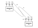
- FIG. 1 schematically shows a configuration example of a millimeter wave radio communication system according to an embodiment of the present invention.
- the illustrated wireless communication system includes a wireless communication device 100 and a wireless communication device 200.
- the wireless communication devices 100 and 200 can wirelessly communicate with each other using both the first communication method and the second communication method described above.
- the first communication system that uses microwaves is not as straight as compared to millimeter waves, and has little attenuation during reflection. Therefore, when the wireless communication apparatuses 100 and 200 perform wireless communication according to the first communication method, they can communicate with each other without considering the directivity of the transmission beam and the reception beam.
- the second communication method uses millimeter waves, the straight communication property is strong and the attenuation at the time of reflection is large.
- the wireless communication device 100 includes an antenna 110 for transmitting and receiving wireless signals according to the first communication method and a plurality of antennas 160a to 160n for transmitting and receiving wireless signals according to the second communication method. I have. Then, by adjusting the weights of the signals transmitted via antennas 160a ⁇ 160n, and controls the directivity B t transmit beam during a wireless communication in accordance with the second communication method. In the illustrated example, the transmission beam B t is directed in the direction of the position of the wireless communication device 200 that is the communication partner.
- the wireless communication apparatus 200 includes an antenna 210 for transmitting / receiving a wireless signal according to the first communication method and a plurality of antennas 260a to 260n for transmitting / receiving a wireless signal according to the second communication method. Then, by adjusting the weights of signals received via antennas 260a ⁇ 260n, and controls the directivity B r of the received beam at the time of radio communication in accordance with the second communication method.
- the reception beam Br is directed in the direction of the position of the wireless communication device 100 serving as a communication partner.
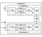
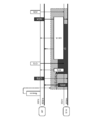
- FIG. 2 shows a configuration example of the wireless communication device 100.
- the illustrated wireless communication apparatus 100 may operate as a broadband router or a wireless access point. Although not shown, the wireless communication apparatus 200 may have the same configuration.
- the wireless communication device 100 includes an antenna 110, a first wireless communication unit 120, a storage unit 150, a plurality of antennas 160a to 160n, and a second wireless communication unit 170.
- the first wireless communication unit 120 includes a first analog unit 122, an AD (Analog-to-Digital) conversion unit 124, a DA (Digital-to-Analog) conversion unit 126, and a first digital unit 130.
- the control unit 140 is configured.
- the second wireless communication unit 170 includes a second analog unit 172, an AD conversion unit 174, a DA conversion unit 176, a second digital unit 180, and a control unit 190.
- the antenna 110 is an antenna used for wireless communication according to the first communication method.
- the antenna 110 transmits, for example, a control signal for coordinating in the second communication method such as a beacon according to the first communication method using microwaves. Further, the antenna 110 receives a control signal for coordinating in the second communication method such as a beacon in accordance with the first communication method, and outputs the control signal to the first analog unit 122.
- the first analog unit 122 typically corresponds to an RF (Radio Frequency) circuit for transmitting and receiving a radio signal according to the first communication method.
- the first analog unit 122 amplifies the RF reception signal received by the antenna 110 with low noise, down-converts it, and outputs it to the AD conversion unit 124 at the subsequent stage.
- the first analog unit 122 also up-converts the transmission signal converted into the analog signal by the DA conversion unit 126 into the RF band, amplifies the power, and outputs the amplified signal to the antenna 110.
- the AD conversion unit 124 converts the analog reception signal input from the first analog unit 122 into a digital signal and outputs the digital signal to the first digital unit 130 at the subsequent stage. Further, the DA conversion unit 126 converts the digital transmission signal input from the first digital unit 130 into an analog signal and outputs the analog signal to the first analog unit 122.
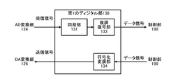
- FIG. 3 shows an example of the internal configuration of the first digital unit 130.
- the first digital unit 130 includes a synchronization unit 131, a demodulation / decoding unit 132, and a coded modulation unit 133.
- the synchronization unit 131 synchronizes the reception processing start timing with respect to the reception signal of the antenna 110 in accordance with the detection of the first preamble of the frame of the first communication method.
- the demodulation / decoding unit 132 demodulates and decodes the received signal according to an arbitrary modulation method and coding method used for the first communication method, acquires a data signal, and outputs the data signal to the control unit 140.
- the encoding modulation unit 133 encodes and modulates the data signal input from the control unit 140 according to an arbitrary encoding method and modulation method used for the first communication method, generates a transmission signal, and generates a DA.
- the data is output to the conversion unit 126.
- the control unit 140 is configured using an arithmetic device such as a microprocessor, for example, and controls the overall operation of the first wireless communication unit 120. For example, the control unit 140 sends a control signal for coordinating in the second communication system such as a beacon to the first digital unit 130 in response to a request from a predetermined application (such as an upper layer program of a communication protocol). Output. In addition, when a decoded control signal is input from the first digital unit 130, the control unit 140 acquires information related to coordination in the second communication method described in the control signal, and stores the information. Stored in the unit 150 as appropriate.
- a control signal for coordinating in the second communication system such as a beacon
- a predetermined application such as an upper layer program of a communication protocol
- the storage unit 150 is configured by a writable recording medium such as a semiconductor memory, for example, and loads a program for executing communication processing by the wireless communication apparatus 100 or stores various parameter values as a work memory. Used. In addition, the storage unit 150 stores parameter values for specifying an optimal transmission / reception beam pattern for the wireless communication by the second wireless communication unit 170 according to the second communication method.
- a writable recording medium such as a semiconductor memory
- the plurality of antennas 160a to 160n are used for wireless communication according to the second communication method. Specifically, antennas 160a to 160n transmit radio signals weighted using a predetermined weighting factor using millimeter waves, respectively. Further, the antennas 160 a to 160 n receive millimeter wave radio signals and output them to the second analog unit 172.
- the second analog unit 172 typically corresponds to an RF circuit for transmitting and receiving a radio signal according to the second communication method. That is, the second analog unit 172 performs low-noise amplification and down-conversion on the plurality of received signals respectively received by the antennas 160a to 160n, and outputs them to the AD conversion unit 174 at the subsequent stage. The second analog unit 172 up-converts the plurality of transmission signals converted into analog signals by the DA conversion unit 176 to the RF band, amplifies the power, and outputs the amplified signals to the antennas 160a to 160n.
- the AD conversion unit 174 converts each of the plurality of analog reception signals input from the second analog unit 172 into a digital signal and outputs the digital signal to the second digital unit 180 at the subsequent stage. Further, the DA conversion unit 176 converts each of the plurality of digital transmission signals input from the second digital unit 180 into analog signals and outputs the analog signals to the second analog unit 172.
- the second digital unit 180 is typically a circuit for demodulating and decoding a received signal according to the second communication scheme, and a circuit for encoding and modulating a transmission signal according to the second communication scheme. Composed.
- FIG. 4 shows an example of the internal configuration of the second digital unit 180.
- the second digital unit 180 includes a synchronization unit 181, a reception beam processing unit 182, a power calculation unit 183, a determination unit 184, a demodulation decoding unit 185, a coded modulation unit 186, a transmission
- the beam processing unit 187 is configured.
- the synchronization unit 181 synchronizes the reception processing start timing according to the preamble at the beginning of the frame for the plurality of reception signals received by the plurality of antennas 160a to 160n and outputs the received signal to the reception beam processing unit 182.
- the reception beam processing unit 182 controls the directivity of the reception beam by weighting the plurality of reception signals input from the synchronization unit 181 according to, for example, a uniform distribution or a Taylor distribution. Reception beam processing section 182 then outputs the weighted reception signal to power calculation section 183 and demodulation decoding section 185.
- the power calculation unit 183 calculates reception power of reception signals transmitted / received by each transmission / reception beam pattern, and sequentially outputs them to the determination unit 184. Then, the determination unit 184 determines an optimal transmission beam pattern and a parameter value for specifying the reception beam pattern based on the reception power value input from the power calculation unit 183.
- the optimum beam pattern is typically a beam pattern in which a series of received power values input from the power calculation unit 183 with respect to one beam learning signal is a maximum value.
- the demodulation / decoding unit 185 demodulates and decodes the reception signal weighted by the reception beam processing unit 182 according to an arbitrary modulation method and encoding method used for the second communication method, and obtains a data signal. Then, the demodulation / decoding unit 185 outputs the acquired data signal to the control unit 190.
- the encoding modulation unit 186 encodes and modulates the data signal input from the control unit 190 in accordance with an arbitrary encoding method and modulation method used for the second communication method, and generates a transmission signal. Then, the encoding modulation unit 186 outputs the generated transmission signal to the transmission beam processing unit 187.
- the transmission beam processing unit 187 generates a plurality of transmission signals weighted according to, for example, uniform distribution or Taylor distribution from the transmission signal input from the encoding modulation unit 186, and controls the directivity of the transmission beam.
- the value of the weight used by the transmission beam processing unit 187 is specified by a directivity control signal input from the control unit 190, for example.
- the plurality of transmission signals weighted by the transmission beam processing unit 187 are output to the DA conversion unit 176, respectively.
- the control unit 190 is configured using an arithmetic device such as a microprocessor, for example, and controls the overall operation of the second wireless communication unit 170. Further, the control unit 190 acquires a parameter value for specifying an optimal transmission beam pattern from the storage unit 150, and directivity for forming an optimal transmission beam pattern specified based on the parameter value. The control signal is output to the transmission beam processing unit 187 in the second digital unit 180. Thereby, the transmission beam at the time of wireless transmission according to the second communication method by the wireless communication device 100 is directed to the direction in which the communication partner is located.
- an arithmetic device such as a microprocessor
- FIG. 5 shows an example of a transmission beam pattern that can be formed by the wireless communication apparatus 100 by directivity control of the transmission beam by the transmission beam processing unit 187.
- the wireless communication apparatus 100 can form ten transmission beam patterns B t0 to B t9 .
- the transmission beam patterns B t0 to B t9 have directivities in different directions by 36 degrees on the plane where the radio communication apparatus 100 is located.
- the transmission beam processing unit 187 uses any one of the ten transmission beam patterns B t0 to B t9 to transmit directivity. Wireless signals can be transmitted from the antennas 160a to 160n.
- the reception beam pattern that can be formed by the wireless communication apparatus 100 may be the same beam pattern as the transmission beams B t0 to B t9 shown in FIG. That is, the reception beam processing unit 182 matches any one (or a combination of two or more) of the ten reception beam patterns B r0 to B r9 according to the directivity control signal from the control unit 190.
- radio signals according to the second communication method can be received by the antennas 160a to 160n.
- weighting factors for the antennas 160a to 160n for forming these transmission / reception beam patterns B t0 to B t9 and B r0 to B r9 are stored in advance.
- the transmission beam pattern and the reception beam pattern that can be formed by the wireless communication apparatus 100 are not limited to the example shown in FIG.
- the plurality of antennas 160a to 160n can be configured so as to form a transmission beam pattern or a reception beam pattern having directivity in various directions in a three-dimensional space.
- the wireless communication apparatus 100 uses a first wireless communication unit 120 that performs wireless communication using microwaves and a second wireless communication unit 170 that performs wireless communication using millimeter waves. Specifically, a control signal for taking coordination in the second communication method such as a beacon is transmitted and received by the first wireless communication unit 120 and the antenna 110, and after the coordination is taken, the second wireless communication unit 170 is transmitted. In addition, transmission / reception is performed by a plurality of antennas 160a to 160n.
- the illustrated communication system is an infrastructure network composed of one access point (AP) and two terminal stations (STA1, STA2). These three communication stations (AP, STA1, STA2) are all configured using the wireless communication device 100 shown in FIG.
- the transmission / reception beams of the second wireless communication unit 170 of each terminal station (STA1, STA2) are all directed to the access point (AP) side, and each terminal station (STA1, STA2) accesses
- a communication link is established with the point (AP) by the second communication method, and can be used as a link for high-speed data transmission between the access point (AP) and each terminal station (STA1, STA2).
- the communication link by the 1st communication system between an access point (AP) and each terminal station (STA1, STA2) is effective, and can be utilized as a link for coordination.
- the communication link according to the second communication method is invalid, in other words, for high-speed data transmission between the terminal stations STA1 and STA2.
- the link has not been established.
- the communication link by the first communication method between the terminal stations STA1 and STA2 is effective, and can be supplementarily used as a communication link for coordination.
- the access point (AP) periodically transmits a beacon that describes operation information of a basic service set (BSS) to which the station belongs, according to the first communication method.
- a cycle for transmitting a beacon is referred to as a “frame cycle”.
- the beacon is a control signal for coordinating with each terminal station (STA1, STA2).
- the beacon transmitted according to the first communication method includes the BSS operation information during communication according to the first communication method and the BSS operation information during communication according to the second communication method. . Therefore, each terminal station (STA1, STA2) receives the beacon from the access point (AP) and communicates with the first communication method and the second communication method in the BBS according to the operation information of the BSS described. Operation can be performed. That is, the access point (AP) can coordinate the wireless communication according to the second communication method by supplementarily using the first communication method.
- FIG. 7 illustrates the operation information of the BSS at the time of communication according to the second communication method described in the beacon.
- schedule information such as transmission timing (STA1 Tx Timing, STA2 Tx Timing, etc
- STA1, STA2 Tx Timing In the second communication method assigned to each terminal station (STA1, STA2) within the frame period as operation information.
- Information on the communication capability in the second communication method of the access point (AP) itself or the BSS Capability Info
- the communication capability information (Capability Info) referred to here includes communication capability information (60 GHz Capability) regarding the used frequency band, capability information (Beamforming Capability) regarding beam forming of the access point (AP) itself, and the like.
- ⁇ GHz capability As communication capability information (60 GHz capability) regarding the used frequency band, channels (Supported Channels) supported by the access point (AP) (but when multiple channels are allocated to the 60 GHz band) are currently used in the BSS ( In other words, available channels are described.
- information (Supported Beam Pattern) related to a transmission / reception beam pattern (see FIG. 5) supported by the access point (AP) is described as beamforming capability information (Beamforming Capability).
- the access point (AP) when the beacon transmitted according to the first communication method is also described with the operation information of the BSS at the time of communication according to the second communication method, the access point (AP) must establish the directivity of the transmission / reception beam. For example, for each terminal station (STA1, STA2) that does not receive a radio signal according to the second communication method, information that the communication partner exists before establishing directivity is used as an auxiliary to the first communication method. There is an advantage that it can be transmitted.
- the access point (AP) tries to notify the operation information of the BSS in the second communication scheme to each terminal station (STA1, STA2) according to the second communication scheme, the radio signal is transmitted only in the direction in which the transmission / reception beam is directed. Therefore, it is necessary to transmit the same information a plurality of times to each terminal station located in a different direction, resulting in an increase in overhead.
- the operation information of the BSS at the time of communication according to the first communication method described in the beacon is the same as the description of the beacon defined in IEEE 802.11 using microwaves, for example. The detailed explanation is omitted.
- each terminal station uses the second communication method by using each transmission section (STA1 Tx Timing, STA2 Tx Timing) allocated from the access point through the beacon.
- STA1 Tx Timing STA1 Tx Timing
- STA2 Tx Timing STA1 Tx Timing
- the data transmission source communication station transmits a transmission start request frame RTS (Request To Send) and responds to reception of the confirmation notification frame CTS (Clear To Send) from the data transmission destination communication station. Start sending data frames.
- RTS transmission station receives the CTS and sets a transmission suspension period (NAV: Network Allocation Vector) to avoid collision with the data frame.
- CTS transmitting station receives the RTS and sets a transmission stop period to avoid a collision with an ACK returned for data frame reception.
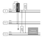
- FIG. 8 shows an example of a signal transmission / reception sequence performed using the RTS / CTS method in the wireless communication system shown in FIG. However, in the figure, it is assumed that both the access point (AP) and each terminal station (STA1, STA2) have learned the optimal directivity of the antennas 160-a,.
- the access point (AP) broadcasts a beacon according to the first communication method in the 5 GHz band every predetermined frame period, and each terminal station (STA1, STA2) receives this beacon, thereby the access point (AP). Under the control, the coordination for the second communication method in the 60 GHz band is taken together with the coordination for the first communication method in the BSS.
- Schedule information (Schedule Info) is described (see the above and FIG. 7).
- the section indicated by the left oblique line is assigned to the transmission section according to the second communication method of one terminal station (STA1) in the frame period
- the section indicated by diagonal lines is assigned to the transmission section according to the second communication method of the other terminal station (STA2).
- the terminal stations (STA1, STA2) can perform wireless communication according to the second communication method in a contention-free manner.
- the terminal station (STA1) and the terminal station (STA2) do not direct transmission / reception beams and control frames such as RTS and CTS transmitted according to the second communication method do not reach, the terminal station (STA1) and the terminal station (STA2) The other terminal station cannot be set to NAV.
- transmission sections are individually assigned to the terminal station (STA1) and the terminal station (STA2), radio signals according to the second communication scheme do not collide with each other.
- the terminal station (STA1) and the terminal station (STA2) can perform communication operations according to the second communication method after being coordinated.
- the terminal station (STA1) in the transmission section (left hatched portion) assigned to itself, the RTS / CTS hand according to the second communication method with the access point (AP). Perform shake procedure.
- the terminal station (STA1) When the terminal station (STA1) enters the transmission interval assigned to itself, the terminal station (STA1) first confirms that the media is clear for a certain period of time by the procedure of CSMA, and then sets the RTS to the access point (AP). 2 is transmitted according to the communication method.
- the access point (AP) prepares for the wireless communication according to the second communication method with the terminal station (STA1).
- the directivity of the second wireless communication unit 170 is controlled so as to obtain an optimum transmission / reception beam pattern for STA1), and a reception operation is started.
- the access point (AP) performs CTS that feeds back that the RTS has been received after a predetermined frame interval SIFS (Short Inter Frame Space) has passed. Reply according to the method.
- SIFS Short Inter Frame Space
- the terminal station (STA1) When the terminal station (STA1) confirms that the medium is clear by successfully receiving the CTS, the terminal station (STA1) transmits a data frame according to the second communication method after the SIFS has elapsed. Although not shown, the terminal station (STA1) may transmit the data frame according to the first communication method in parallel with the data frame according to the second communication method.
- the access point (AP) waits for a data frame after transmitting the CTS.
- an ACK is returned after the SIFS has elapsed.
- the terminal station (STA1) recognizes that the series of RTS / CTS handshake procedures has been successfully completed.
- the terminal station (STA2) executes the RTS / CTS handshake procedure according to the second communication method with the access point (AP) within the transmission section (right hatched portion) allocated to itself. To do.
- the terminal station When entering the transmission section assigned to itself, the terminal station (STA2) first confirms that the media is clear only for a certain period by the CSMA procedure, and then transmits the RTS to the access point (AP). To do.
- the access point (AP) prepares for the terminal station (STA2) in preparation for wireless communication according to the second communication method with the terminal station (STA2).
- the directivity of the second wireless communication unit 170 is controlled so as to obtain an optimum transmission / reception beam pattern for STA2), and a reception operation is started.
- the access point (AP) returns a CTS that feeds back that the RTS has been received after a predetermined frame interval SIFS has elapsed.
- the terminal station (STA2) When the terminal station (STA2) confirms that the medium is clear by receiving the CTS successfully, the terminal station (STA2) transmits a data frame after the SIFS has elapsed. Although not shown, the terminal station (STA2) may transmit the data frame according to the first communication method in parallel with the data frame according to the second communication method.
- the access point (AP) waits for a data frame after transmitting the CTS.
- ACK is returned after SIFS has elapsed.
- the terminal station (STA2) recognizes that a series of RTS / CTS handshake procedures have been successfully completed.
- the signal transmission / reception sequence shown in FIG. 8 has been described on the premise that learning of directivity of the transmission / reception beam pattern of each communication station has been completed.
- an example of an optimal transmission / reception beam pattern learning method will be described.
- the gist of the present invention is not limited to a specific learning method.
- FIG. 9 shows an example of a signal format of a beam learning signal transmitted from the wireless communication apparatus 100 and used by the communication partner for beam learning. However, in the figure, the description of the header portion is omitted.
- the illustrated beam learning signal BTF Beam Training Field
- the learning signal sequence placed on the beam learning signal BTF may be, for example, a random pattern of BPSK (Binary Phase Shift Keying).
- the beam learning signal shown in the figure is obtained by multiplexing a learning signal sequence for each of the transmission beam patterns B t0 to B t9 by time division.
- the beam learning signal BTF is composed of ten time slots T0 to T9 respectively corresponding to the transmission beam patterns B t0 to B t9 shown in FIG.
- 10 kinds of learning signal sequences weighted by weighting factors for forming the transmission beam patterns B t0 to B t9 for a predetermined known signal sequence are sequentially transmitted.
- the Accordingly, the directivity of the transmission beam of the beam learning signal sequentially changes as shown in the transmission beam patterns B t0 to B t9 shown in FIG. 5 for each time slot T0 to T9.
- the receiving side that receives this beam learning signal BTF observes the power level of the received signal for each time slot T0 to T9 of the beam learning signal BTF (that is, for each learning signal series). As a result, the power level of the received signal has a prominent value in any time slot of the beam learning signal BTF.
- the time slot at which the power level of the received signal peaks changes according to the relative position with the transmitting side that transmits the beam learning signal BTF. Then, the transmission beam pattern corresponding to the time slot at which the reception power level reaches a peak can be determined as an optimal transmission beam pattern for the transmission side.
- the receiving side of the beam learning signal BTF can also form ten reception beam patterns B r0 to B R9 similar to the transmission beam patterns B t0 to B t9 shown in FIG. .
- each of the time slots T0 to T9 of the beam learning signal BTF is further divided into 10 small sections ST0 to ST9, and 10 different received beam patterns B r0 to B r9 are used in each of the small sections ST0 to ST9.
- the received signal is weighted.
- the first subsection ST0 of the time slot T0 is the received beam pattern B r0
- the second subsection ST1 of the time slot T0 is the received beam pattern B r1
- One sub-section ST0 is associated with the received beam pattern B r0,.
- the power calculator 183 shown in FIG. 4 calculates the received power of the received signals transmitted and received in the above-described 100 transmission / reception patterns, and sequentially outputs the received power to the determination unit 184. Then, the determination unit 184 determines parameter values for specifying the optimum transmission beam pattern and reception beam pattern based on the received reception power value.
- the optimum beam pattern is typically a beam pattern in which a series of received power values input from the power calculation unit 283 for one beam learning signal is a maximum value.
- the parameter value for specifying the optimum transmission beam pattern may be any time slot number (T0 to T9) of the beam learning signal BTF, for example. Further, the parameter value for specifying the optimum reception beam pattern may be, for example, the small section number (ST0 to ST9) shown in FIG.
- the determination unit 184 outputs the parameter value determined in this way to the control unit 190. Further, parameter values (T0 to T9) for specifying an optimum transmission beam pattern may be fed back to the transmission side of the beam learning signal BTF. However, since this feedback procedure is not directly related to the gist of the present invention, the description is omitted in this specification.
- the transmission / reception beam pattern is learned between the communication stations that are the communication partners with each other, if the terminal station subsequently moves or a shielding object enters the communication path, it will be used up to the previous time, even temporarily. The resulting transmit / receive beam pattern is not available and the directional communication link becomes invalid.
- the present inventors can determine whether or not the transmission / reception beam pattern used last time can be used prior to data communication according to the second communication method, that is, whether or not the directional communication link is effective. It is proposed to adopt a “link maintenance” procedure that checks every certain period of time. Specifically, the link maintenance frame for link maintenance is exchanged according to the second communication method between the communication stations that have established the directional communication link, and depending on whether or not each other's frame has been received, The effectiveness of the directional communication link can be confirmed. In order to realize such a link maintenance procedure, it is necessary to decide in advance the time for executing the maintenance, that is, the timing at which the communication partner transmits the link maintenance frame. For the notification of the link maintenance frame transmission timing, the first communication method that is non-directional and has no flying distance problem can be used as an auxiliary.
- the access point (AP) individually assigns a transmission section to each terminal station (STA1, STA2), and each terminal station (STA1, STA2) Data is transmitted to the access point (AP) using the RTS / CTS handshake procedure.
- the timing at which each terminal station (STA1, STA2) transmits the RTS is known for the access point (AP), and the CTS is returned from the access point (AP) to each terminal station (STA1, STA2). Timing is known. Therefore, the RTS and CTS control frames can be used as link maintenance frames.
- the terminal stations (STA1, STA2) always transmit an RTS that also serves as a link maintenance frame even if there is no transmission data to the access point (AP) in each transmission section. .
- FIG. 10 shows an example of a signal transmission / reception sequence for performing link maintenance using the RTS / CTS handshake procedure.
- a beacon frame period has already been established between the access point (AP) and each terminal station (STA1, STA2). Further, the access point (AP) removes the disabled directional communication link and reschedules the allocation of the transmission period of the frame period.
- the access point (AP) broadcasts a beacon according to the first communication method in the 5 GHz band for every predetermined frame period, and coordinates the second communication method in the 60 GHz band. And the transmission area according to a 2nd communication system is allocated with respect to each terminal station (STA1, STA2) through a beacon, respectively.
- the terminal station (STA1) uses the RTS that previously used the RTS, which also serves as a link maintenance frame, to the access point (AP) after a predetermined period has elapsed from the beginning of the transmission section assigned to the terminal station (STA1). Is transmitted in accordance with the second communication method using again. However, the terminal station (STA1) always transmits the RTS for link maintenance even when there is no transmission data to the access point (AP) in its transmission section.
- the access point (AP) has received the RTS from the terminal station (STA1) in the transmission section assigned to the terminal station (STA1) according to the second communication method that reuses the directional communication link that used the previous time. By this, it can be confirmed that the directional communication link used last time with the terminal station (STA1) is valid.
- the access point (AP) may update the state of the directional communication link (optimum reception beam pattern) through the RTS handshake. Then, after a predetermined frame interval SIFS has elapsed after receiving the RTS, the access point (AP) returns a CTS that also serves as a link maintenance frame in accordance with the second communication method.
- the terminal station (STA1) can confirm that the directional communication link used last time with the access point (AP) is valid in addition to the clear media.
- the terminal station (STA1) may update the state of the directional communication link (optimum reception beam pattern) through the CTS handshake.
- the terminal station (STA1) transmits the data frame according to the second communication method reusing the directional communication link that used the previous time after the SIFS has elapsed after receiving the CTS.
- the access point (AP) has successfully received the data frame, it returns an ACK.
- the terminal station (STA1) recognizes that the series of RTS / CTS handshake procedures has been successfully completed.
- the terminal station (STA2) uses the RTS that used the RTS that also serves as a link maintenance frame toward the access point (AP) after a predetermined period has elapsed from the beginning of the transmission interval assigned to the terminal station (STA2).
- the RTS is transmitted according to the second communication method using the communication link again.
- the terminal station (STA2) always transmits the RTS for link maintenance even when there is no transmission data to the access point (AP) in its transmission section.
- the access point (AP) uses the directional communication link that used the RTS from the terminal station (STA2) at the expected time again in the transmission interval assigned to the terminal station (STA2). Since it cannot receive according to a system, it can recognize that the directional communication link utilized last time with the terminal station (STA2) has become invalid.
- the access point (AP) removes the transmission section to the terminal station (STA2) where the directional communication link has become invalid, and reschedules the allocation of the transmission section of the frame period. Then, the access point (AP) broadcasts a Schedule frame describing the rescheduled contents according to the first communication method.
- the terminal station (STA1) can receive the Schedule frame according to the first communication method.
- the terminal station (STA1) can recognize the timing of the transmission section newly assigned to itself by analyzing the description content of the frame. Then, as described above, the terminal station (STA1) sets the RTS that also serves as a link maintenance frame to the access point (AP) after a predetermined period has elapsed from the beginning of the transmission interval assigned to itself. What is necessary is just to transmit according to 2 communication systems.
- FIG. 11 shows a processing procedure for the access point (AP) to realize the signal transmission / reception sequence shown in FIG. 10 in the form of a flowchart.
- the access point (AP) transmits a beacon according to the 5 GHz band, that is, the first communication method when the beacon transmission time for each frame period arrives (Yes in step S1) (step S2).
- a beacon BSS operation information at the time of communication according to the first communication method and BSS operation information at the time of communication according to the second communication method are described, and each terminal station in the vicinity receives the beacon. Coordination within the BSS is taken.
- transmission sections allocated to each terminal station within the frame period are described as BSS operational information during communication according to the second communication method.
- the access point (AP) When the access point (AP) reaches the start time of the transmission section assigned to any terminal station (STA) within the frame period (Yes in step S3), the access point (AP) The directivity of the second wireless communication unit 170 is controlled so as to be a pattern, and the reception operation according to the 60 GHz band, that is, the second communication method is started (step S4).
- the access point (AP) can receive an RTS that also serves as a link maintenance frame from the terminal station (STA) at the expected time (Yes in step S5), the terminal station (STA) It can be confirmed that the directional communication link used last time is effective.
- the access point (AP) may update the state of the directional communication link (optimum reception beam pattern) through the RTS handshake.
- the access point (AP) also serves as a link maintenance frame in accordance with the second communication method in which the previously used directional communication link is reused after a predetermined frame interval SIFS has elapsed since the reception of the RTS.
- the CTS is returned (step S6), and a data frame from the terminal station (STA) is received (step S7).
- the access point (AP) has successfully received the data frame, it returns an ACK.
- the access point (AP) uses the RTS that also serves as the link maintenance frame from the terminal station (STA) at the expected time and uses the directional communication link that has been used last time to re-use the second communication method. Therefore, it can be recognized that the previously used directional communication link with the terminal station (STA) has become invalid.
- the access point (AP) removes the transmission section to the terminal station (STA2) in which the directional communication link has become invalid, and reschedules the allocation of the transmission section of the frame period (step S8).
- the gist of the present invention is not limited to a specific rescheduling process, description of the rescheduling process is omitted here.
- the access point (AP) broadcasts a Reschedule frame describing the rescheduled contents according to the first communication method with no flying distance problem (step S9).
- FIG. 12 shows a processing procedure for the terminal stations (STA1, STA2) to realize the signal transmission / reception sequence shown in FIG. 10 in the form of a flowchart.
- the terminal station (STA) When the reception time of the beacon for each frame period arrives (Yes in step S11), the terminal station (STA) starts the reception operation according to the 5 GHz band, that is, the first communication method, and receives the beacon from the access point (AP). (Step S12).
- the BSS operation information at the time of communication according to the second communication method is described along with the BSS operation information at the time of communication according to the first communication method, and the terminal station (STA)
- the assigned transmission interval can be recognized.
- the terminal station (STA) may recognize the transmission section assigned to itself by receiving a Schedule frame (described above).
- the terminal station (STA) When the terminal station (STA) enters its transmission section notified by the beacon or the Reschedule frame, after a predetermined period has elapsed from the beginning (Yes in step S13), the terminal station (STA) is directed to the access point (AP).
- the RTS that also serves as the maintenance frame is transmitted according to the second communication method that re-uses the directional communication link that was used last time (step S14). However, the terminal station (STA) always transmits the RTS for link maintenance even if there is no transmission data to the access point (AP) in its transmission section.
- the terminal station (STA) After transmitting the RTS, the terminal station (STA) waits for reception of the CTS from the access point (AP). Then, by receiving the CTS according to the second communication method that re-uses the directional communication link that used the previous time (Yes in step S15), the terminal station (STA) uses the previously used directivity with the access point (AP). It can be confirmed that the communication link is valid.
- the terminal station (STA1) may update the state of the directional communication link (optimum reception beam pattern) through the CTS handshake.
- the terminal station (STA) confirms that the media is clear by receiving the CTS (Yes in step S15). Then, the terminal station (STA) transmits a data frame according to the second communication method in which the previously used directional communication link is reused after SIFS has elapsed since the reception of the CTS (step S16). Thereafter, the terminal station (STA) recognizes that the series of RTS / CTS handshake procedures has been successfully completed by receiving the ACK.
- FIG. 13 shows another example of a signal transmission / reception sequence for performing link maintenance using the RTS / CTS handshake procedure.
- a beacon frame period has already been established between the access point (AP) and each terminal station (STA1, STA2).
- STA2 takes the initiative to relearn the directivity of the transmission / reception beam with respect to the access point (AP).
- the access point (AP) broadcasts a beacon according to the first communication method in the 5 GHz band for every predetermined frame period, and coordinates the second communication method in the 60 GHz band. And the transmission area according to a 2nd communication system is allocated with respect to each terminal station (STA1, STA2) through a beacon, respectively.
- the terminal station (STA1) uses the RTS that previously used the RTS, which also serves as a link maintenance frame, to the access point (AP) after a predetermined period has elapsed from the beginning of the transmission section assigned to the terminal station (STA1). Is transmitted in accordance with the second communication method using again.
- the access point (AP) received the RTS from the terminal station (STA1) within the transmission section allocated to the terminal station (STA1) according to the second communication method that reused the directional communication link that was used last time. Thus, it can be confirmed that the directional communication link used last time with the terminal station (STA1) is valid.
- the access point (AP) may update the state of the directional communication link (optimum reception beam pattern) through the RTS handshake. Then, after a predetermined frame interval SIFS has elapsed after receiving the RTS, the access point (AP) returns a CTS that also serves as a link maintenance frame in accordance with the second communication method.
- the terminal station (STA1) receives the CTS in accordance with the second communication method using the directional communication link used last time, so that the media is clear and the previous use with the access point (AP). It can be confirmed that the directed communication link is effective.
- the terminal station (STA1) may update the state of the directional communication link (optimum reception beam pattern) through the CTS handshake.
- the terminal station (STA1) transmits the data frame according to the second communication method reusing the directional communication link that used the previous time after the SIFS has elapsed after receiving the CTS.
- the access point (AP) has successfully received the data frame, it returns an ACK.
- the terminal station (STA1) recognizes that the series of RTS / CTS handshake procedures has been successfully completed.
- the terminal station (STA2) uses the RTS that used the RTS that also serves as a link maintenance frame toward the access point (AP) after a predetermined period has elapsed from the beginning of the transmission interval assigned to the terminal station (STA2). Transmission is performed according to the second communication method using the communication link again.
- the access point (AP) receives the RTS from the terminal station (STA2) at the expected time in accordance with the second communication method using the directional communication link that used the previous time, so that the previous time with the terminal station (STA2) It can be confirmed that the used directional communication link is effective. Then, after a predetermined frame interval SIFS has elapsed since the reception of the RTS, the access point (AP) uses the CTS that also serves as the link maintenance frame and re-uses the directional communication link that has been used last time. Reply according to the communication method.
- the terminal station (STA2) receives the CTS from the access point (AP) at the expected time after transmitting the RTS according to the second communication method using the directional communication link that used the previous time again. Therefore, it can be recognized that the directional communication link used last time with the access point (AP) has become invalid.
- the terminal station (STA2) transmits a training request frame that requests re-learning of the directivity of the transmission / reception beam with the access point (AP). Since the Training Request frame is transmitted according to the first communication method with no flying distance problem, the Training Request frame is delivered even to a communication partner that does not receive the link maintenance frame transmitted according to the second communication method. It is expected.
- the access point (AP) When the access point (AP) receives the training request frame, the access point (AP) recognizes that the directional communication link used last time is invalid, and the training response indicating that the re-learning request for the directivity of the transmission / reception beam has been accepted. Reply the frame. Since the directional communication link used last time is invalid, the training response frame is also transmitted according to the first communication method.
- processing for re-learning the directivity of the transmission / reception beam between the terminal station (STA2) and the access point (AP) is executed.
- the beam learning signal BTF shown in FIG. 9 can be used, but the gist of the present invention is not limited to a specific relearning method.
- the signal transmission / reception sequence examples shown in FIG. 10 and FIG. 13 both use RTS and CTS control frames as link maintenance frames, but wireless communication conforms to the second communication method between terminal stations (STA1 and STA2). It is assumed that communication is contention-free, that is, an infrastructure network.
- FIG. 14 shows an example of a signal transmission / reception sequence in which link maintenance is performed using the RTS / CTS handshake procedure when only CTS is used as a link maintenance frame.
- link maintenance is performed using the RTS / CTS handshake procedure when only CTS is used as a link maintenance frame.
- the directivity of the transmission / reception beam is relearned by the RTS transmission side.
- the data transmission side (RTS transmission side: STA_Tx) first confirms that the media is clear for a certain period of time by the CSMA procedure, and then sends the second RTS to the data reception side (CTS transmission side: STA_Rx). Transmit according to the communication method.
- the data receiving side (STA_Rx) returns a CTS that also serves as a link maintenance frame according to the second communication method after a predetermined frame interval SIFS has elapsed in response to receiving the RTS.
- the data transmission side (STA_Tx) waits for the reception of the CTS returned from the data reception side (STA_Rx) after transmitting the RTS. Then, the data transmission side (STA_Tx) receives the CTS in accordance with the second communication method that re-uses the directional communication link that was used last time, so that the media is clear and the data reception side (STA_Rx) It can be confirmed that the directional communication link used last time is effective.
- the data transmission side (STA_Tx) may update the state (optimum reception beam pattern) of the directional communication link through the CTS handshake.
- the data transmission side (STA_Tx) transmits the data frame according to the second communication method after the SIFS has elapsed since the reception of the CTS. Further, the data receiving side (STA_Rx) returns an ACK after successfully receiving the data frame. The data transmission side (STA_Tx) recognizes that the series of RTS / CTS handshake procedures has been successfully completed by receiving the ACK.
- the data transmission side (STA_Tx) confirms that the medium is clear for a certain period by the CSMA procedure, and then transmits the RTS to the data reception side (STA_Rx) according to the second communication method.
- the data receiving side (STA_Rx) receives the RTS, and after the predetermined frame interval SIFS has elapsed, the CTS that also serves as the link maintenance frame is used for the directional communication link that was previously used. Reply according to the second communication method used again.
- the data transmission side (STA_Tx) waits for the reception of the CTS after transmitting the RTS, but at the expected time, the data transmission side (STA_Tx) again uses the directional communication link that previously used the CTS from the data reception side (STA_Rx). Since it cannot receive according to the used 2nd communication system, it can recognize that the directional communication link utilized last time with the data receiving side (STA_Rx) has become invalid.
- the data transmission side (STA_Tx) transmits a training request frame that requests re-learning of the directivity of the transmission / reception beam with the data reception side (STA_Rx). Since the Training Request frame is transmitted according to the first communication method with no flying distance problem, the Training Request frame is delivered even to a communication partner that does not receive the link maintenance frame transmitted according to the second communication method. It is expected.
- the data receiving side (STA_Rx) When the data receiving side (STA_Rx) receives the training request frame, the data receiving side (STA_Rx) recognizes that the directional communication link used last time is invalid and trains indicating that the re-learning request for the directivity of the transmission / reception beam has been accepted. A response frame is returned. Since the directional communication link used last time is invalid, the training response frame is also transmitted according to the first communication method instead of the second communication method.
- a process for re-learning the directivity of the transmission / reception beam between the data transmission side (STA_Tx) and the data reception side (STA_Rx) is executed.
- the beam learning signal BTF shown in FIG. 9 can be used, but the gist of the present invention is not limited to a specific relearning method.
- FIG. 15 shows a processing procedure for realizing the signal transmission / reception sequence shown in FIG. 14 by the data transmission side (RTS transmission side: STA_Tx) in the form of a flowchart.
- RTS transmission side: STA_Tx data transmission side
- the communication operation for each transmission section of each terminal station (STA1, STA2) in the signal transmission / reception sequence shown in FIG. 13 is the same as the processing procedure shown in the flowchart.
- step S21 When a data transmission request is generated (Yes in step S21), the data transmission side (STA_Tx) confirms that the medium is clear for a certain period by the CSMA procedure, and then proceeds to the data reception side (STA_Rx) toward the RTS. Is transmitted according to the second communication method (step S22), and reception of the CTS that also serves as a link maintenance frame is awaited.
- the data transmission side (STA_Tx) performs the second communication again using the directional communication link that used the CTS from the data reception side (STA_Rx) last time after the predetermined frame interval SIFS has elapsed since the RTS was transmitted.
- the data transmission side (STA_Tx) may update the state (optimum reception beam pattern) of the directional communication link through the CTS handshake.
- the data transmission side (STA_Tx) transmits a data frame in accordance with the second communication method using the directional communication link used last time after the SIFS has elapsed after receiving the CTS (step S24). Further, the data transmission side (STA_Tx) recognizes that the series of RTS / CTS handshake procedures have been successfully completed by receiving ACK from the data reception side (STA_Rx).
- the data transmission side (STA_Tx) waits for the reception of CTS after transmitting the RTS, but at the expected time, the CTS from the data reception side (STA_Rx) is used for the directional communication link that was previously used. If it cannot be received according to the second communication method used again (No in step S23), it recognizes that the previously used directional communication link with the data receiving side (STA_Rx) has become invalid. be able to.
- the data transmission side (STA_Tx) has a training request frame that requires re-learning of the directivity of transmission / reception beams with the data reception side (STA_Rx), and the request frame has no flying distance problem.
- Transmission is performed according to the first communication method (step S25).
- step S26 When the data transmission side (STA_Tx) receives the training response frame returned from the data reception side (STA_Rx) (Yes in step S26), the transmission / reception beam is transmitted between the data transmission side (STA_Tx) and the data reception side (STA_Rx).
- a process for re-learning the directivity (Training Procedure) is executed (step S27).
- the beam learning signal BTF shown in FIG. 9 can be used, but the gist of the present invention is not limited to a specific relearning method.
- FIG. 16 shows a processing procedure for realizing the signal transmission / reception sequence shown in FIG. 14 by the data reception side (CTS transmission side: STA_Rx) in the form of a flowchart.
- the data reception side (STA_Rx) performs link maintenance after a predetermined frame interval SIFS has elapsed.
- a CTS that also serves as a frame is returned in accordance with the second communication method that re-uses the directional communication link that was used last time (step S32).
- the data reception side (STA_Rx) waits for reception according to the second communication method after returning the CTS, and when a data frame arrives from the data transmission side (STA_Tx) (Yes in step S33), the previously used directivity is used.
- the data frame is received in accordance with the second communication method using the mobile communication link again (step S34).
- the data receiving side (STA_Rx) has successfully received the data frame, it returns an ACK.
- the data receiving side (STA_Rx) cannot receive the data frame from the data transmitting side (STA_Tx) according to the second communication method (No in step S33). Instead, the training request frame is transmitted to the first communication.
- the first training response frame indicating that the directional communication link used last time is invalid and indicating that the re-learning request for the directivity of the transmitted / received beam has been received is received.
- a reply is made according to the communication method (step S36).
- a process (Training Procedure) for re-learning the directivity of the transmission / reception beam between the data transmission side (STA_Tx) and the data reception side (STA_Rx) is executed (step S37).
- the beam learning signal BTF shown in FIG. 9 can be used, but the gist of the present invention is not limited to a specific relearning method.
- RTS and CTS are also used as a link maintenance frame
- CTS is used as a link maintenance frame. It is.
- any signal transmission / reception sequence is premised on using the RTS / CTS handshake procedure in the BSS according to the second communication method.
- the former signal transmission / reception sequence shown in FIG. 10 and FIG. 13 in the BSS according to the second communication method, it is necessary to allocate a transmission section for each terminal station and to determine the RTS transmission timing of each terminal station in advance. is there.
- FIG. 17 shows a signal transmission / reception sequence example in which link maintenance is performed using a dedicated link maintenance frame without using the RTS / CTS handshake procedure.
- AP access point
- STA1, STA2 terminal station
- the access point (AP) broadcasts a beacon according to the first communication method in the 5 GHz band for every predetermined frame period, and coordinates the second communication method in the 60 GHz band.
- the timing at which the access point (AP) broadcasts the link maintenance frame according to the second communication method of the 60 GHz band is notified through the beacon.
- each terminal station (STA1, STA2) transmits the link maintenance frame according to the second communication method that reuses the previously used directional communication link. Wait for reception. Further, when the timing for informing the link maintenance frame arrives, the access point (AP) reports the link maintenance frame omnidirectionally according to the second communication method.
- One terminal station (STA1) successfully receives the link maintenance frame from the access point (AP) in accordance with the second communication method reusing the previously used directional communication link, thereby It can be confirmed that the directional communication link used last time with (AP) is valid.
- the terminal station (STA1) may update the state of the directional communication link (optimum reception beam pattern) through the CTS handshake.
- the other terminal station (STA2) cannot receive the link maintenance frame from the access point (AP) at the expected time according to the second communication method using the previously used directional communication link again. It is possible to recognize that the directional communication link used last time with the access point (AP) has become invalid.
- the terminal station (STA2) transmits a training request frame that requests re-learning of the directivity of the transmission / reception beam with the access point (AP). Since the Training Request frame is transmitted according to the first communication method with no flying distance problem, the Training Request frame is delivered even to a communication partner that does not receive the link maintenance frame transmitted according to the second communication method. It is expected.
- the access point (AP) When the access point (AP) receives the training request frame, the access point (AP) recognizes that the directional communication link used last time is invalid, and the training response indicating that the re-learning request for the directivity of the transmission / reception beam has been accepted. Reply the frame. Since the directional communication link used last time is invalid, the training response frame is also transmitted according to the first communication method.
- processing for re-learning the directivity of the transmission / reception beam between the terminal station (STA2) and the access point (AP) is executed.
- the beam learning signal BTF shown in FIG. 9 can be used, but the gist of the present invention is not limited to a specific relearning method.
- FIG. 18 shows, in the form of a flowchart, a processing procedure for the access point (AP) on the transmission side of the link maintenance frame to realize the signal transmission / reception sequence shown in FIG.
- the access point (AP) transmits a beacon according to the 5 GHz band, that is, the first communication method when the beacon transmission time for each frame period arrives (Yes in step S41) (step S42).
- a beacon BSS operation information at the time of communication according to the first communication method and BSS operation information at the time of communication according to the second communication method are described, and each terminal station in the vicinity receives the beacon. Coordination within the BSS is taken. Also, information regarding the timing at which the access point (AP) transmits link maintenance within the frame period is described as BSS operation information during communication according to the second communication method.
- the access point (AP) reports the link maintenance frame omnidirectionally according to the second communication method (step S44).
- the access point (AP) can confirm that the directional communication link used last time with each terminal station (STA1, STA2) is valid. In this case, the access point (AP) performs a data exchange operation with each terminal station (STA1, STA2) according to the second communication method by reusing the directional communication link used last time (step). S48).
- the access point (AP) has the directional communication link used last time with the transmission source of the training request frame. You can recognize that it has become invalid.
- the access point (AP) returns a training response frame indicating that the re-learning request for the directivity of the transmission / reception beam has been accepted in accordance with the first communication method (step S46). Then, processing (Training Procedure) for re-learning the directivity of the transmission / reception beam with the requesting terminal station is executed (step S47).
- processing Training Procedure
- the beam learning signal BTF shown in FIG. 9 can be used, but the gist of the present invention is not limited to a specific relearning method.
- step S48 a directional communication link is formed using the transmission / reception beam obtained by re-learning, and data exchange operation with the terminal station is performed according to the second communication method.
- FIG. 19 shows, in the form of a flowchart, a processing procedure for the terminal stations (STA1, STA2) on the link maintenance frame receiving side to realize the signal transmission / reception sequence shown in FIG.
- the terminal station (STA) starts the reception operation according to the 5 GHz band, that is, the first communication method, and receives the beacon from the access point (AP).
- Step S52 BSS operation information at the time of communication according to the first communication method and BSS operation information at the time of communication according to the second communication method are described. Also, information regarding the timing at which the access point (AP) transmits link maintenance within the frame period is described as BSS operation information during communication according to the second communication method.
- Step S53 the terminal station (STA), in accordance with the second communication method using the directional communication link used last time, re-links the maintenance frame. (Step S54).
- the terminal station (STA) was able to successfully receive the link maintenance frame from the access point (AP) in accordance with the second communication method using the directional communication link used last time again.
- a data exchange operation is performed with the access point (AP) in accordance with the second communication method using the previously used directional communication link again (step S55).
- step S54 it recognizes that the directional communication link used last time with the access point (AP) has become invalid.
- the terminal station (STA) performs a training request frame for requesting re-learning of the directivity of transmission / reception beams with the access point (AP), and the request frame is a first communication with no flying distance problem. Transmission is performed according to the method (step S56).
- the terminal station (STA) When the terminal station (STA) receives the training response frame returned from the access point (AP) (Yes in step S57), the terminal station (STA) directs transmission / reception beams between the data transmission side (STA_Tx) and the data reception side (STA_Rx).
- a process for re-learning sex (Training Procedure) is executed (step S58).
- the beam learning signal BTF shown in FIG. 9 can be used, but the gist of the present invention is not limited to a specific relearning method.
- a directional communication link is formed using the transmission / reception beam obtained by re-learning, and data exchange operation with the access point (AP) is performed according to the second communication method (step S55).
- the communication according to the second communication method is coordinated by the communication according to the first communication method, while the data transmission after the coordination is taken is exclusively the second communication.
- This is a BSS operation mode in which the first communication method is used in an auxiliary manner.
- a BSS operation mode in which data transmission according to the first communication method is performed in parallel with data transmission according to the second communication method is also conceivable.
- data that requires stability is transmitted according to the first communication method, while data (for example, large-capacity content) that requires a communication rate is transmitted according to the second communication method.
- data for example, large-capacity content
- the second communication method By allocating transmission data to each other, it is possible to improve throughput.
- the operation mode in which both the first communication method and the second communication method are used for data transmission further includes an operation mode in which scheduling is performed synchronously in both communication methods and data transmission is performed completely simultaneously, and each communication method. Can be roughly divided into operation modes in which scheduling is performed independently.
- FIG. 20 shows an example of a signal transmission / reception sequence between an access point (AP) and a terminal station (STA) in the case where scheduling is performed in synchronization with the first and second communication methods and data transmission is performed completely simultaneously. Show.
- the access point (AP) provides a contention-free service to the terminal station (STA).
- the access point (AP) broadcasts a beacon in accordance with the first communication method in the 5 GHz band at every predetermined frame period, and the terminal station (STA) receives the beacon to control the access point (AP).
- the coordination for the second communication scheme in the 60 GHz band is taken.
- schedule information such as transmission timing in the second communication method assigned to the terminal station (STA) is described as BSS operation information during communication according to the second communication method (see FIG. 7 and FIG. 7). See In the example shown in FIG. 20, according to the schedule information described in the beacon, the section indicated by the left oblique line is assigned to the transmission section according to the second communication scheme of the terminal station (STA) within the frame period, and the terminal station (STA ) Can perform wireless communication according to the second communication method without contention.
- the terminal station (STA) executes the RTS / CTS handshake procedure with the access point (AP) within the transmission section (left hatched portion) assigned to itself. That is, when the terminal station (STA) enters the transmission section assigned to itself, the terminal station (STA) transmits the RTS to the access point (AP) according to the second communication method. In addition, the terminal station (STA) simultaneously transmits the RTS according to the first communication method.
- the access point (AP) prepares for the terminal station (STA) in preparation for wireless communication according to the second communication method with the terminal station (STA).
- the directivity of the second wireless communication unit 170 is controlled so as to obtain an optimum transmission / reception beam pattern for STA), and a reception operation is started.
- the access point (AP) performs CTS feedback that the RTS has been received after a predetermined frame interval SIFS has elapsed according to the first and second communication methods. Reply each.
- the terminal station (STA) When the terminal station (STA) confirms that the media is clear by successfully receiving the CTS, after the SIFS has elapsed, the terminal station (STA) distributes the transmission data to the first and second communication methods, In synchronization with the data frame transmission according to the communication method, data frame transmission according to the first communication method is performed in parallel.
- the access point (AP) waits for a data frame after transmitting the CTS.
- ACK is returned according to the first and second communication methods after the SIFS has elapsed.
- the terminal station (STA1) recognizes that the series of RTS / CTS handshake procedures has been successfully completed.
- FIG. 21 shows an example of a signal transmission / reception sequence between the access point (AP) and the terminal station (STA) when scheduling is performed independently in the first and second communication methods.
- AP access point
- STA terminal station
- the access point (AP) broadcasts a beacon in accordance with the first communication method in the 5 GHz band at every predetermined frame period, and the terminal station (STA) receives the beacon to control the access point (AP).
- the coordination for the second communication scheme in the 60 GHz band is taken.
- schedule information such as transmission timing in the second communication method assigned to the terminal station (STA1) is described as BSS operation information during communication according to the second communication method (see FIG. 7 and FIG. 7). See In the example shown in FIG. 21, according to the schedule information described in the beacon, the section indicated by the left oblique line is assigned to the transmission section according to the second communication method of the terminal station (STA) within the frame period, and the terminal station (STA ) Can perform wireless communication according to the second communication method without contention.
- the terminal station (STA) executes the RTS / CTS handshake procedure with the access point (AP) within the transmission section (left hatched portion) assigned to itself. That is, when the terminal station (STA) enters the transmission section assigned to itself, the terminal station (STA) transmits the RTS to the access point (AP) according to the second communication method.
- the access point (AP) prepares for the terminal station (STA) in preparation for wireless communication according to the second communication method with the terminal station (STA).
- the directivity of the second wireless communication unit 170 is controlled so as to obtain an optimum transmission / reception beam pattern for STA), and a reception operation is started.
- the access point (AP) sends a CTS that feeds back that the RTS has been received after a predetermined frame interval SIFS has passed. Reply according to the communication method.
- the transmission data distributed to the second communication method is transmitted to the second communication method after the SIFS has elapsed. Send according to.
- the access point (AP) waits for a data frame after transmitting the CTS.
- ACK is returned according to the second communication method after the SIFS has elapsed.
- the terminal station (STA1) recognizes that a series of RTS / CTS handshake procedures according to the second communication method have been successfully completed.
- a communication procedure based on an access right rule different from that in the second communication method is performed.
- a contention-type service is provided for the first communication method independently of the transmission interval set in the second communication method, and the terminal station (STA) is in an empty channel state. Data transmission can be performed accordingly.
- the terminal station (STA) When the terminal station (STA) enters the transmission interval assigned to itself, the terminal station (STA) first confirms that the media is clear for a certain period of time according to the CSMA procedure, and then sets the RTS to the access point (AP). 1 according to the communication method.
- the access point (AP) starts the reception operation according to the first communication method in which the start time of the transmission section assigned to the terminal station (STA) arrives. Then, in response to the reception of the RTS, after a predetermined frame interval SIFS has passed, a CTS for feeding back that the RTS has been received is returned according to the first communication method.
- the transmission data distributed to the first communication method is transmitted to the first communication method after the SIFS has elapsed. Send according to.
- the access point (AP) waits for a data frame after transmitting the CTS.
- ACK is returned according to the second communication method after the SIFS has elapsed.
- the terminal station (STA1) recognizes that a series of RTS / CTS handshake procedures according to the first communication method have been successfully completed.
- the wireless communication device 100 that operates as an access point (AP) or a terminal station (STA) includes, for example, a personal computer (PC), a mobile phone, a personal digital assistant such as a PDA (Personal Digital Assistant), a portable music player, It may be a wireless communication module mounted on an information device such as a game machine, or a television receiver or other information home appliance.
- AP access point
- STA terminal station
- PC personal computer
- PDA Personal Digital Assistant
- portable music player It may be a wireless communication module mounted on an information device such as a game machine, or a television receiver or other information home appliance.
- FIG. 22 shows a configuration example of an information device on which the modularized wireless communication device 100 is mounted.
- a CPU (Central Processing Unit) 1 executes a program stored in a ROM (Read Only Memory) 2 or a hard disk drive (HDD) 11 under a program execution environment provided by an operating system (OS).
- OS operating system
- the received frame synchronization process described later or a part of the process may be realized in a form in which the CPU 1 executes a predetermined program.
- ROM 2 permanently stores program codes such as POST (Power On Self Test) and BIOS (Basic Input Output System).
- BIOS Basic Input Output System
- a RAM (Random Access Memory) 3 loads a program stored in the ROM 2 or HDD (Hard Disk Drive) 11 when the CPU 1 executes it, or temporarily holds work data of the program being executed. Used for. These are connected to each other by a local bus 4 directly connected to a local pin of the CPU 1.
- the local bus 4 is connected to an input / output bus 6 such as a PCI (Peripheral Component Interconnect) bus via a bridge 5.
- PCI Peripheral Component Interconnect
- the keyboard 8 and the pointing device 9 are input devices operated by the user.
- the display 10 includes an LCD (Liquid Crystal Display) or a CRT (Cathode Ray Tube), and displays various types of information as text and images.
- HDD 11 is a drive unit having a built-in hard disk as a recording medium, and drives the hard disk.
- the hard disk is used for installing programs executed by the CPU 1 such as an operating system and various applications, and for storing data files and the like.
- the communication unit 12 is a wireless communication interface configured by modularizing the wireless communication device 100, and operates as an access point or a terminal station in the infrastructure mode, or operates in the ad hoc mode, and is within a communication range. Communicate with other existing communication terminals. The operation of the wireless communication device 100 is as already described.
- the first communication method is a 5 GHz band used in IEEE802.11a, which is widely used as a wireless LAN standard
- the second communication method is a 60 GHz band used in IEEE802.15.3c.
- the gist of the present invention is not necessarily limited to a specific frequency band.
- the second communication method may be not only millimeter wave communication but also other directional communication.
- Storage unit 160a to 160n Multiple antennas (second communication method) 170 ... second wireless communication unit 172 ... second analog unit 174 ... AD conversion unit 176 ... DA conversion unit 180 ... second digital unit 181 ... synchronization unit 182 ... reception beam processing unit 183 ... power calculation unit 184 ... decision Unit 185 ... demodulation decoding unit 186 ... encoding modulation unit 187 ... transmission beam processing unit 190 ... control unit
Abstract
Selon la présente invention, une coordination appropriée avec une pluralité d'autres extrémités de communication effectuant des communications à onde millimétrique peut être établie. Des faisceaux transmis de chacune d'une pluralité de stations terminales sont dirigés vers un point d'accès et une liaison de communication efficace utilisant un second système de communication est utilisée comme liaison utilisée pour effectuer une transmission de données à vitesse élevée entre le point d'accès et chaque station terminale. Automatiquement, la liaison de communication utilisant le premier système de communication entre le point d'accès et chaque station terminale est efficace et utilisée comme liaison utilisée pour une coordination entre ces derniers. Puisqu'aucun faisceau n'est dirigé vers l'une ou l'autre des stations terminales, la liaison de communication utilisant le second système de communication est inefficace entre les stations terminales. Toutefois, la liaison de communication efficace utilisant le premier système de communication peut être utilisée comme liaison utilisée pour une coordination entre les stations terminales.
Priority Applications (4)
| Application Number | Priority Date | Filing Date | Title |
|---|---|---|---|
| EP10746084.2A EP2403286B1 (fr) | 2009-02-26 | 2010-02-09 | Appareil de communication, procédé de communication, programme informatique et système de communication |
| CN201080007704.1A CN102318392B (zh) | 2009-02-26 | 2010-02-09 | 通信装置和通信方法、计算机程序和通信系统 |
| US13/201,355 US8971817B2 (en) | 2009-02-26 | 2010-02-09 | Communication apparatus and communication method, computer program, and communication system |
| EP18208855.9A EP3512234A1 (fr) | 2009-02-26 | 2010-02-09 | Appareil de communication, procédé de communication, programme informatique et système de communication |
Applications Claiming Priority (2)
| Application Number | Priority Date | Filing Date | Title |
|---|---|---|---|
| JP2009044649A JP5434137B2 (ja) | 2009-02-26 | 2009-02-26 | 通信装置及び通信方法、コンピューター・プログラム、通信システム、並びに情報処理装置 |
| JP2009-044649 | 2009-02-26 |
Publications (1)
| Publication Number | Publication Date |
|---|---|
| WO2010098203A1 true WO2010098203A1 (fr) | 2010-09-02 |
Family
ID=42665413
Family Applications (1)
| Application Number | Title | Priority Date | Filing Date |
|---|---|---|---|
| PCT/JP2010/051898 WO2010098203A1 (fr) | 2009-02-26 | 2010-02-09 | Appareil de communication, procédé de communication, programme informatique et système de communication |
Country Status (5)
| Country | Link |
|---|---|
| US (1) | US8971817B2 (fr) |
| EP (2) | EP2403286B1 (fr) |
| JP (1) | JP5434137B2 (fr) |
| CN (1) | CN102318392B (fr) |
| WO (1) | WO2010098203A1 (fr) |
Cited By (3)
| Publication number | Priority date | Publication date | Assignee | Title |
|---|---|---|---|---|
| WO2013022292A2 (fr) | 2011-08-11 | 2013-02-14 | Samsung Electronics Co., Ltd. | Procédé et appareil de suivi de faisceau dans un système de communication sans fil |
| JP2014524705A (ja) * | 2011-08-16 | 2014-09-22 | サムスン エレクトロニクス カンパニー リミテッド | ビームフォーミングベースの無線通信システムにおける多重アンテナ送信をサポートするための装置及び方法 |
| JP2019536328A (ja) * | 2016-10-25 | 2019-12-12 | クアルコム,インコーポレイテッド | メッセージの制御された送信および受信をサポートする方法および装置 |
Families Citing this family (24)
| Publication number | Priority date | Publication date | Assignee | Title |
|---|---|---|---|---|
| CN102545972A (zh) * | 2012-01-18 | 2012-07-04 | 中兴通讯股份有限公司 | 一种近距离无线通信设备及近距离无线通信方法 |
| US9521602B2 (en) * | 2013-08-09 | 2016-12-13 | Qualcomm Incorporated | Method and apparatus for management of high frequency communications in a low frequency wireless network |
| WO2015085550A1 (fr) * | 2013-12-12 | 2015-06-18 | 华为技术有限公司 | Procédé de synchronisation d'équipement d'utilisateur, et équipement d'utilisateur |
| CN106797640B (zh) | 2014-04-09 | 2020-06-26 | Idac控股公司 | Mmw物理层下行链路信道调度和控制信令 |
| US10097321B2 (en) * | 2014-05-08 | 2018-10-09 | Qualcomm Incorporated | Cooperative techniques between lower-frequency carriers and millimeter-wave channels for discovery and synchronization and beamforming |
| US10659135B2 (en) * | 2014-06-16 | 2020-05-19 | Qualcomm Incorporated | Coordinated discovery of MMW connection points and UES |
| US9474013B2 (en) | 2014-06-16 | 2016-10-18 | Qualcomm Incorporated | Method and apparatus for connection point discovery and association in a directional wireless network |
| US9451536B2 (en) * | 2014-06-18 | 2016-09-20 | Qualcomm Incorporated | UE initiated discovery in assisted millimeter wavelength wireless access networks |
| US10321435B2 (en) | 2014-06-27 | 2019-06-11 | Qualcomm Incorporated | Method and apparatus for lightweight messaging during initial synchronization, discovery, and association in directional wireless systems |
| JP2016015572A (ja) * | 2014-07-01 | 2016-01-28 | 株式会社リコー | 無線通信システム、無線通信装置、プログラムおよび記録媒体 |
| BR112017005590A2 (pt) | 2014-09-30 | 2018-01-23 | Ericsson Telefon Ab L M | nós de acesso e método de formação de feixe para receber e transmitir sinais em rede de comunicação sem fio |
| WO2016067701A1 (fr) * | 2014-10-31 | 2016-05-06 | ソニー株式会社 | Dispositif de communication sans fil |
| EP3240352A4 (fr) * | 2014-12-26 | 2018-01-10 | Nationz Technologies Inc. | Procédé et appareil de communication sans fil et système d'application et dispositif correspondant |
| CN106304081B (zh) * | 2015-05-21 | 2020-06-09 | 国民技术股份有限公司 | 无线通信方法、装置及其应用系统和设备 |
| CN106507499A (zh) * | 2015-09-06 | 2017-03-15 | 国民技术股份有限公司 | 一种无线通信方法、装置和及其应用设备 |
| JP6081636B1 (ja) | 2016-03-14 | 2017-02-15 | パナソニック株式会社 | 通信システム、サーバ装置および通信制御方法 |
| CN112887000B (zh) * | 2016-05-31 | 2022-07-15 | 中兴通讯股份有限公司 | 信息反馈方法、装置及系统 |
| US10575240B2 (en) | 2017-09-12 | 2020-02-25 | Sony Corporation | Multi-band millimeter wave network discovery |
| WO2019053001A1 (fr) * | 2017-09-14 | 2019-03-21 | Fraunhofer-Gesellschaft zur Förderung der angewandten Forschung e.V. | Émetteur-récepteur double comprenant un premier et un deuxième émetteur-récepteur |
| US10716053B2 (en) | 2017-10-02 | 2020-07-14 | Sony Corporation | Adaptive network discovery signaling |
| CN107888225A (zh) * | 2017-10-27 | 2018-04-06 | 深圳市太赫兹科技创新研究院有限公司 | 无线通信方法及设备 |
| CN111713080B (zh) * | 2017-12-29 | 2023-11-07 | 诺基亚技术有限公司 | 小区中的增强型业务容量 |
| US10728733B2 (en) | 2018-01-12 | 2020-07-28 | Sony Corporation | Multi-band millimeter wave discovery in WLAN distribution networks |
| US10742299B2 (en) | 2018-08-20 | 2020-08-11 | Sony Corporation | Allocation and directional information distribution in millimeter wave WLAN networks |
Citations (7)
| Publication number | Priority date | Publication date | Assignee | Title |
|---|---|---|---|---|
| JP2004032062A (ja) * | 2002-06-21 | 2004-01-29 | Nec Corp | 無線通信システムおよび中継器 |
| JP3544891B2 (ja) | 1999-04-16 | 2004-07-21 | シャープ株式会社 | 無線伝送システム、及びアンテナの指向性方向の決定方法 |
| JP2007517474A (ja) * | 2003-12-30 | 2007-06-28 | インテル・コーポレーション | ワイヤレス・ネットワーク内でダウンリンクsdmaを実現する方法と装置 |
| JP2008502173A (ja) * | 2004-06-04 | 2008-01-24 | ミツビシ・エレクトリック・リサーチ・ラボラトリーズ・インコーポレイテッド | 無線通信ネットワークおよび無線通信ネットワークのチャネルを介してパケットを送信するための方法 |
| JP2008048119A (ja) | 2006-08-15 | 2008-02-28 | Nippon Hoso Kyokai <Nhk> | 無線端末装置 |
| JP2008512954A (ja) * | 2004-09-10 | 2008-04-24 | インターデイジタル テクノロジー コーポレーション | ワイヤレスローカルエリアネットワークにおけるスマートアンテナの実施 |
| JP2008199593A (ja) * | 2007-01-19 | 2008-08-28 | Matsushita Electric Ind Co Ltd | 無線通信方法および無線通信装置 |
Family Cites Families (11)
| Publication number | Priority date | Publication date | Assignee | Title |
|---|---|---|---|---|
| JPS544891B2 (fr) | 1972-03-24 | 1979-03-12 | ||
| EP1237335B1 (fr) * | 2001-02-21 | 2006-07-05 | Nippon Telegraph and Telephone Corporation | Système de radiocommunication par paquets à bonds multiples |
| US8213438B2 (en) * | 2003-12-19 | 2012-07-03 | Iwics Inc. | Data transport protocol for a multi-station network |
| CN100550800C (zh) * | 2004-03-05 | 2009-10-14 | 株式会社东芝 | 无线通信方法和设备 |
| US20050233734A1 (en) * | 2004-04-16 | 2005-10-20 | Samsung Electronics Co., Ltd. | Wireless network and mobile stations implementing protocol revision independent features |
| US20090102927A1 (en) * | 2006-02-10 | 2009-04-23 | Akihiro Tatsuta | Wireless transmission system for registering source device in sink device |
| US8320942B2 (en) * | 2006-06-13 | 2012-11-27 | Intel Corporation | Wireless device with directional antennas for use in millimeter-wave peer-to-peer networks and methods for adaptive beam steering |
| US8238835B2 (en) * | 2006-12-07 | 2012-08-07 | Mitsubishi Electric Corporation | Wireless communication system, wireless terminal station, wireless base station, and wireless communication method |
| CN101369837B (zh) * | 2007-05-29 | 2013-02-06 | 三星电子株式会社 | 利用有限前馈信道进行波束形成的设备和方法 |
| US8130737B2 (en) * | 2008-03-12 | 2012-03-06 | Samsung Electronics Co., Ltd. | System and method for a multiple hop wireless network |
| US8116694B2 (en) * | 2008-12-23 | 2012-02-14 | Nokia Corporation | System for facilitating beam training |
-
2009
- 2009-02-26 JP JP2009044649A patent/JP5434137B2/ja not_active Expired - Fee Related
-
2010
- 2010-02-09 US US13/201,355 patent/US8971817B2/en not_active Expired - Fee Related
- 2010-02-09 CN CN201080007704.1A patent/CN102318392B/zh not_active Expired - Fee Related
- 2010-02-09 WO PCT/JP2010/051898 patent/WO2010098203A1/fr active Application Filing
- 2010-02-09 EP EP10746084.2A patent/EP2403286B1/fr not_active Not-in-force
- 2010-02-09 EP EP18208855.9A patent/EP3512234A1/fr not_active Withdrawn
Patent Citations (7)
| Publication number | Priority date | Publication date | Assignee | Title |
|---|---|---|---|---|
| JP3544891B2 (ja) | 1999-04-16 | 2004-07-21 | シャープ株式会社 | 無線伝送システム、及びアンテナの指向性方向の決定方法 |
| JP2004032062A (ja) * | 2002-06-21 | 2004-01-29 | Nec Corp | 無線通信システムおよび中継器 |
| JP2007517474A (ja) * | 2003-12-30 | 2007-06-28 | インテル・コーポレーション | ワイヤレス・ネットワーク内でダウンリンクsdmaを実現する方法と装置 |
| JP2008502173A (ja) * | 2004-06-04 | 2008-01-24 | ミツビシ・エレクトリック・リサーチ・ラボラトリーズ・インコーポレイテッド | 無線通信ネットワークおよび無線通信ネットワークのチャネルを介してパケットを送信するための方法 |
| JP2008512954A (ja) * | 2004-09-10 | 2008-04-24 | インターデイジタル テクノロジー コーポレーション | ワイヤレスローカルエリアネットワークにおけるスマートアンテナの実施 |
| JP2008048119A (ja) | 2006-08-15 | 2008-02-28 | Nippon Hoso Kyokai <Nhk> | 無線端末装置 |
| JP2008199593A (ja) * | 2007-01-19 | 2008-08-28 | Matsushita Electric Ind Co Ltd | 無線通信方法および無線通信装置 |
Cited By (5)
| Publication number | Priority date | Publication date | Assignee | Title |
|---|---|---|---|---|
| WO2013022292A2 (fr) | 2011-08-11 | 2013-02-14 | Samsung Electronics Co., Ltd. | Procédé et appareil de suivi de faisceau dans un système de communication sans fil |
| US10148331B2 (en) | 2011-08-11 | 2018-12-04 | Samsung Electronics Co., Ltd. | Method and apparatus for tracking beam in wireless communication system |
| EP2742603B1 (fr) * | 2011-08-11 | 2022-02-16 | Samsung Electronics Co., Ltd. | Procédé et appareil de suivi de faisceau dans un système de communication sans fil |
| JP2014524705A (ja) * | 2011-08-16 | 2014-09-22 | サムスン エレクトロニクス カンパニー リミテッド | ビームフォーミングベースの無線通信システムにおける多重アンテナ送信をサポートするための装置及び方法 |
| JP2019536328A (ja) * | 2016-10-25 | 2019-12-12 | クアルコム,インコーポレイテッド | メッセージの制御された送信および受信をサポートする方法および装置 |
Also Published As
| Publication number | Publication date |
|---|---|
| JP2010200161A (ja) | 2010-09-09 |
| EP2403286A1 (fr) | 2012-01-04 |
| JP5434137B2 (ja) | 2014-03-05 |
| US8971817B2 (en) | 2015-03-03 |
| EP3512234A1 (fr) | 2019-07-17 |
| EP2403286B1 (fr) | 2019-01-16 |
| CN102318392B (zh) | 2014-07-30 |
| EP2403286A4 (fr) | 2016-02-24 |
| CN102318392A (zh) | 2012-01-11 |
| US20120028588A1 (en) | 2012-02-02 |
Similar Documents
| Publication | Publication Date | Title |
|---|---|---|
| JP5434137B2 (ja) | 通信装置及び通信方法、コンピューター・プログラム、通信システム、並びに情報処理装置 | |
| US8736491B2 (en) | Communication apparatus and communication method, computer program, and communication system | |
| JP5278035B2 (ja) | 通信装置及び通信方法、コンピューター・プログラム、並びに通信システム | |
| US8619751B2 (en) | Communication apparatus, communication method, computer program, and communication system | |
| US8824320B2 (en) | Communication apparatus, communication method, computer program, and communication system | |
| US9860911B2 (en) | Communication apparatus, communication method, and communication system | |
| US9178574B2 (en) | Beaconing and superframe structure for millimeter wave wireless technologies | |
| US20140148107A1 (en) | Using Multiple Frequency Bands With Beamforming Assistance in a Wireless Network | |
| CN101873156B (zh) | 无线通信装置、无线通信方法以及无线通信系统 | |
| EP2481253A2 (fr) | Période configurable fondée sur la contention dans des systèmes sans fil à ondes millimétriques | |
| KR101131917B1 (ko) | 무선 통신 네트워크에서의 통신 방법, 대응하는 스테이션 및 네트워크 | |
| KR20130128028A (ko) | 통신 시스템에서 협업 통신을 수행하는 장치 및 방법 |
Legal Events
| Date | Code | Title | Description |
|---|---|---|---|
| WWE | Wipo information: entry into national phase |
Ref document number: 201080007704.1 Country of ref document: CN |
|
| 121 | Ep: the epo has been informed by wipo that ep was designated in this application |
Ref document number: 10746084 Country of ref document: EP Kind code of ref document: A1 |
|
| WWE | Wipo information: entry into national phase |
Ref document number: 13201355 Country of ref document: US |
|
| WWE | Wipo information: entry into national phase |
Ref document number: 2010746084 Country of ref document: EP |
|
| NENP | Non-entry into the national phase |
Ref country code: DE |