WO2010097939A1 - インクジェットプリンタ、インクジェットヘッド、及び印刷方法 - Google Patents
インクジェットプリンタ、インクジェットヘッド、及び印刷方法 Download PDFInfo
- Publication number
- WO2010097939A1 WO2010097939A1 PCT/JP2009/053694 JP2009053694W WO2010097939A1 WO 2010097939 A1 WO2010097939 A1 WO 2010097939A1 JP 2009053694 W JP2009053694 W JP 2009053694W WO 2010097939 A1 WO2010097939 A1 WO 2010097939A1
- Authority
- WO
- WIPO (PCT)
- Prior art keywords
- airflow
- air flow
- nozzle
- ink
- medium
- Prior art date
- Legal status (The legal status is an assumption and is not a legal conclusion. Google has not performed a legal analysis and makes no representation as to the accuracy of the status listed.)
- Ceased
Links
Images



Classifications
-
- B—PERFORMING OPERATIONS; TRANSPORTING
- B41—PRINTING; LINING MACHINES; TYPEWRITERS; STAMPS
- B41J—TYPEWRITERS; SELECTIVE PRINTING MECHANISMS, i.e. MECHANISMS PRINTING OTHERWISE THAN FROM A FORME; CORRECTION OF TYPOGRAPHICAL ERRORS
- B41J2/00—Typewriters or selective printing mechanisms characterised by the printing or marking process for which they are designed
- B41J2/005—Typewriters or selective printing mechanisms characterised by the printing or marking process for which they are designed characterised by bringing liquid or particles selectively into contact with a printing material
- B41J2/01—Ink jet
- B41J2/015—Ink jet characterised by the jet generation process
- B41J2/04—Ink jet characterised by the jet generation process generating single droplets or particles on demand
-
- B—PERFORMING OPERATIONS; TRANSPORTING
- B41—PRINTING; LINING MACHINES; TYPEWRITERS; STAMPS
- B41J—TYPEWRITERS; SELECTIVE PRINTING MECHANISMS, i.e. MECHANISMS PRINTING OTHERWISE THAN FROM A FORME; CORRECTION OF TYPOGRAPHICAL ERRORS
- B41J2202/00—Embodiments of or processes related to ink-jet or thermal heads
- B41J2202/01—Embodiments of or processes related to ink-jet heads
- B41J2202/02—Air-assisted ejection
Definitions
- the present invention relates to an ink jet printer, an ink jet head, and a printing method.
- ink jet printers that perform printing by ejecting ink droplets from nozzles have been widely used.
- it has been desired to further reduce the size of ink droplets in response to the increasing demand for printing accuracy of inkjet printers.
- distance space between the inkjet head and the medium depending on the application.
- the kinetic energy of the flying droplet is proportional to its mass. Further, the mass of the droplet is proportional to the cube of its radius r (r 3 ).
- the radius of the droplet is, for example, a radius when the shape of the droplet is approximated to a sphere.
- the air resistance received by the flying droplet in the air has a component proportional to the radius r and a component proportional to the square of the radius r (r 2 ). Therefore, the air resistance in the entire, and be proportional to a value between r ⁇ r 2.
- the influence of the air resistance becomes more prominent when the droplet size is reduced.
- An object of this invention is to provide the inkjet printer, inkjet head, and printing method which can solve said subject.
- Patent Document 1 relating to a bump forming apparatus that discharges molten solder from a nozzle while introducing an inert gas was discovered.
- Patent Document 2 relating to an ink jet recording apparatus using an air flow and an electrostatic force has been discovered.
- the configuration described in these patent documents is a configuration for solving a problem completely different from the present invention.
- the configuration is also different from the present invention.
- An inkjet printer including an inkjet head that ejects ink droplets toward a medium, wherein the inkjet head heads the medium along the ink droplets ejected from the nozzles and nozzles that eject the ink droplets onto the medium.
- An air flow blowing portion that blows out the air flow, and the air flow blowing portion includes a main air flow outlet that blows out a main air flow that is an air flow toward the medium along the ink droplets ejected from the nozzles, and an ink sandwiching the main air flow therebetween.
- a secondary air outlet that blows out a secondary air stream that is an air flow toward the medium along the droplets.
- the main airflow is directed to the medium while in direct contact with the ink droplets, for example.
- the auxiliary airflow is directed to the medium along the ink droplet at a position where the distance from the ink droplet is larger than the distance from the ink droplet to the main airflow.
- the ink droplets are caused to fly in the airflow from the nozzle toward the medium. For this reason, the relative velocity of the ink droplets with respect to the surrounding air is smaller than when no airflow is generated. As a result, the influence of air resistance on the ink droplet is also reduced.
- the subairflow along the main airflow is further blown out, so that the main airflow can be maintained in a laminar flow and the main airflow can be stabilized.
- the speed of the main airflow can be further increased. Therefore, if constituted in this way, the influence of the air resistance which an ink drop receives can be suppressed appropriately.
- the inkjet head may eject ink droplets having a size (capacity) of 1 pl or less (for example, 0.1 to 1 pl) from a nozzle.
- the distance (gap length) between the inkjet head and the medium is large, printing can be performed appropriately. Therefore, with this configuration, for example, the distance (gap length) between the inkjet head and the medium can be increased. Thereby, for example, an ink jet printer having a large gap length can be appropriately provided.
- the gap length may be 10 mm or more (for example, 10 to 100 mm).
- the gap length may be 100 mm or more, for example.
- the nozzle is formed on a nozzle surface that is a surface facing the medium in the inkjet head, the main airflow outlet is formed at a position adjacent to the nozzle on the nozzle surface, and the sub-airflow outlet is the nozzle The surface is formed at a position adjacent to the nozzle across the main air outlet. If comprised in this way, a main airflow and a substream can be blown out appropriately, for example.
- the inkjet head has a plurality of nozzles arranged in a row as a nozzle row on the nozzle surface, and the main air outlet is an area adjacent to both sides of the nozzle row on the nozzle surface, and the nozzle row Provided in the first region extending along the direction, blows out a slit-shaped main airflow across the nozzle row from the first region, and the auxiliary airflow outlet is adjacent to both sides of the first region on the nozzle surface It is provided in the second region extending along the row direction of the nozzle row, and blows out a slit-like sub-air flow toward the medium along the main air flow from the second region.
- the printing speed is improved by simultaneously ejecting ink droplets from a plurality of nozzles.
- the cost may be significantly increased.
- the main airflow and the subairflow are appropriately generated in common for a plurality of nozzles in the nozzle row without causing a significant increase in cost or a decrease in printing resolution. Can be made.
- this makes it possible to more appropriately suppress the influence of air resistance that the ink droplet receives.
- the auxiliary airflow outlet blows out an auxiliary airflow whose speed is 0.3 to 1.2 times that of the main airflow. If comprised in this way, a main airflow can be appropriately supported by a subairflow, for example.
- the speed of the secondary airflow is preferably 0.8 to 1.2 times that of the main airflow.
- the velocity of the main airflow and the velocity of the auxiliary airflow are, for example, initial velocities of the respective airflows.
- the initial velocity of the main airflow is, for example, the velocity of the main airflow immediately after being blown out from the main airflow outlet.
- the initial velocity of the auxiliary airflow is, for example, the velocity of the auxiliary airflow immediately after being blown out from the auxiliary airflow outlet.
- the speed of the sub airflow is substantially the same as or slightly smaller than the main airflow.
- the main airflow and the auxiliary airflow are decelerated before reaching the medium.
- the subairflow which flows outside is easier to decelerate than the main airflow. For this reason, even if the speed of the auxiliary airflow is slightly higher at the initial speed stage, it is reversed or close to a constant speed when it reaches the medium. Therefore, if the speed of the auxiliary airflow is set as described above, the effect of using the auxiliary airflow can be further enhanced.
- the more preferable relationship between the velocities of the main airflow and the auxiliary airflow varies depending on, for example, the position where each is provided and the distance from the nozzle. Therefore, for example, the relationship between the speeds of the main airflow and the auxiliary airflow is preferably adjusted as appropriate according to the configuration of the inkjet head, for example, from the above range.
- the airflow blowing unit may have a plurality of auxiliary airflow outlets whose positions from the main airflow outlet differ from one main airflow outlet.
- the auxiliary airflow outlet closer to the main airflow outlet blows out the auxiliary flow at a speed closer to the main airflow.
- the ink jet head ejects ink droplets from the nozzles at an initial velocity at which the velocity of the ink droplets upon landing on the medium is larger than the velocity of the main airflow when reaching the medium.
- the speed of the ink droplet with respect to the main airflow is zero at the time of landing on the medium, for example, when the airflow is disturbed, the ink droplet landing accuracy may be easily affected.
- the relative velocity of the ink droplets in the direction toward the medium can be maintained positive even at the time of landing.
- ink droplets can be landed with higher accuracy.
- the velocity v1 is in the range of 1.1 to 5 times the velocity v2, for example It is preferable that
- the speed v1 may be set to 1.1 v2 or less. In this case, the speed v1 can be set to a wider range of speeds, for example.
- the speed v1 may be a speed in the range of 0.5 to 5 times the speed v2, for example.
- the speed v1 is more preferably a speed in the range of 0.8 to 5 times the speed v2, for example.
- the ink jet printer further includes an ink storage unit that stores ink before being ejected from the nozzles, and a pressure adjustment unit that adjusts the pressure of the atmosphere of the ink storage unit.
- the pressure of the atmosphere of the ink reservoir is adjusted by transmitting the pressure of the main air current blown from the outlet to the ink reservoir.
- the pressure on the inner side of the ink jet head can be appropriately adjusted according to the pressure of the air flow. Therefore, if comprised in this way, the pressure which arises between the inside of an inkjet head and the exterior can be maintained appropriately at a fixed pressure, for example. Thereby, for example, air can be prevented from being mixed into the ink jet head from the nozzle. In addition, for example, leakage of ink from the nozzle to the outside of the inkjet head can be appropriately prevented.
- the ink reservoir is, for example, a region on the ink supply side inside the ink jet head or an intermediate tank provided in the middle of the ink supply path to the ink jet head.
- the pressure adjustment unit is, for example, a pipe connected to the ink storage unit. This pipe is, for example, a pipe branched from a blower that generates an airflow (main airflow) to an airflow outlet.
- An inkjet head that ejects ink droplets toward a medium, including a nozzle that ejects ink droplets onto the medium, and an airflow blowing unit that blows out an airflow toward the medium along the ink droplets ejected from the nozzles
- the airflow blowing unit has a main airflow outlet that blows out a main airflow that is an airflow toward the medium along the ink droplets ejected from the nozzle, and an airflow that goes toward the medium along the ink droplets with the main airflow interposed therebetween And an auxiliary air outlet for blowing out the auxiliary air flow. If comprised in this way, the effect similar to the structure 1 can be acquired, for example.
- (Configuration 8) A printing method for performing printing by an ink jet method by ejecting ink droplets toward a medium.
- the ink droplets are ejected from a nozzle to a medium, and the medium is ejected along the ink droplets ejected from the nozzle.
- the air flow toward the medium is blown from the air flow blowing unit, and the air flow toward the medium is a main air flow that is the air flow toward the medium along the ink droplets ejected from the nozzles, and the medium along the ink droplets with the main air flow interposed therebetween.
- a sub-air flow that is an air flow toward In this way for example, the same effect as that of Configuration 1 can be obtained.
- FIG. 1 is a diagram illustrating an example of a configuration of an inkjet printer 10 according to an embodiment of the present invention. It is a figure which models and shows the mode of the ink droplet discharged from the nozzle of an inkjet head.
- FIG. 2A shows an example of a state in which printing is performed under conditions where ink droplets reach the medium 50.
- FIG. 2B shows an example of a state when the gap length Lg is further increased.
- 2 is a diagram illustrating an example of a more detailed configuration of the inkjet head 12.
- FIG. 2 is a diagram illustrating a first example of a more detailed configuration of the inkjet head 12.
- FIG. FIG. 4A is a cross-sectional view of the inkjet head 12.
- FIG. 4B is a view of the inkjet head 12 as viewed from the lower surface (nozzle surface) side.
- FIG. 4 is a diagram illustrating a second example of a more detailed configuration of the inkjet head 12.
- FIG. 5A is a cross-sectional view of the inkjet head 12.
- FIG. 5B is a diagram of the inkjet head 12 as viewed from the lower surface (nozzle surface) side.
- FIG. 1 shows an example of the configuration of an inkjet printer 10 according to an embodiment of the present invention.
- the inkjet printer 10 is a printing apparatus that performs printing on the medium 50 by an inkjet method, and includes an inkjet head 12, an ink bottle 14, an ink intermediate tank 16, a blower 18, an airflow supply pipe 20, and an airflow branch pipe 22.
- the inkjet printer 10 is a printing apparatus that performs printing in a multi-pass method, and causes the inkjet head 12 to perform a scanning operation that moves while ejecting ink droplets. Therefore, although not shown, the inkjet printer 10 further includes, for example, a head drive mechanism that moves the inkjet head 12, a transport mechanism that transports the medium 50, and the like.
- the inkjet head 12 is a print head having a nozzle 104 that ejects ink droplets.
- the inkjet head 12 has a plurality of nozzles 104 arranged in a row as a nozzle row 106 on a nozzle surface that is a surface facing the medium 50.
- an air flow blowing unit 120 is provided around the nozzle row 106. The air flow blowing unit 120 blows an air flow toward the medium 50 along the ink droplets ejected from the nozzle 104.
- the ink jet head 12 assists the flight of ink droplets by this air flow. The configuration for blowing out the airflow and the effects thereof will be described in more detail later.
- the ink bottle 14 is a bottle that stores ink used in the inkjet printer 10.
- the ink intermediate tank 16 is a tank that stores ink in the middle of an ink path connecting the ink bottle 14 and the inkjet head 12.
- the ink intermediate tank 16 stores the ink supplied from the ink bottle 14 and supplies the ink to the inkjet head 12 as the printing operation proceeds.
- the ink intermediate tank 16 functions as an ink storage unit that stores ink before being ejected from the nozzles 104.
- an ink supply side region or the ink bottle 14 in the ink jet head 12 may function as an ink storage unit.
- the inkjet printer 10 performs printing using each color ink of YMCK ink.
- the inkjet printer 10 may perform printing by further using ink other than YMCK ink.
- the ink jet printer 10 includes an ink supply configuration such as the ink bottle 14 and the ink intermediate tank 16 for each ink color.
- the blower 18 is an airflow generation device that generates an airflow, and supplies the generated airflow to the inkjet head 12 via the airflow supply pipe 20. As a result, the blower 18 causes the inkjet head 12 to blow an air stream from the air stream blowing unit 120.
- the airflow supply pipe 20 is a pipe that connects the blower 18 and the inkjet head 12, and supplies the airflow generated by the blower 18 to the inkjet head 12.
- the airflow branch pipe 22 is a pipe branched from the airflow supply pipe 20, and is connected to the ink intermediate tank 16 to connect the blower 18 and the ink intermediate tank 16.
- the airflow branching pipe 22 transmits the pressure of the airflow blown by the airflow blowing unit 120 in the inkjet head 12 to the ink intermediate tank 16 that is an ink storage unit.
- the airflow branch pipe 22 functions as a pressure adjusting unit that adjusts the pressure of the atmosphere of the ink storage unit.
- the pressure of the airflow becomes a positive pressure in the vicinity of the nozzle 104, and the backflow of the airflow from the nozzle 104 to the inside of the inkjet head 12 is likely to occur.
- the pressure on the inner side of the inkjet head 12 can be appropriately adjusted according to, for example, the pressure of the airflow. Therefore, the pressure generated between the inside and the outside of the inkjet head 12 can be appropriately maintained at a constant pressure. Thereby, for example, air can be prevented from being mixed into the inkjet head 12 from the nozzle 104. Further, for example, leakage of ink from the nozzle 104 to the outside of the inkjet head 12 can be appropriately prevented.
- the pressure generated between the inside and the outside of the inkjet head 12 can be appropriately maintained at a constant pressure.
- FIG. 2 and FIG. 3 are diagrams for explaining an example of a configuration for blowing out an air flow and an effect thereof.
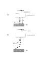
- FIG. 2 is a diagram illustrating a state of ink droplets ejected from the nozzles of the inkjet head, and illustrates how ink droplets fly when no airflow is blown out.
- FIG. 2A shows an example of a state in which printing is performed under conditions where ink droplets reach the medium 50.
- Ink droplets ejected from the nozzles of the inkjet head fly toward the medium 50 while receiving air resistance. If the gap length Lg, which is the distance between the inkjet head and the medium 50, is small with respect to the influence of air resistance, the ink droplets land on the medium 50 as shown in FIG.
- ink When ink is ejected by the inkjet method, droplets smaller than the main droplets called satellites are generated in addition to the main droplets (main droplets) of a preset size according to the required landing accuracy based on the printing accuracy. Often to do. And since this satellite has a small mass and small kinetic energy, it is more susceptible to air resistance than the main droplet. Therefore, the satellite decelerates faster than the main droplet, and cannot easily reach the medium 50 and is easily misted.
- the misted ink adheres to the inside of the print or the medium 50, and there is a possibility that the in-machine dirt or the quality deterioration of the medium 50 may occur. Therefore, it is preferable to consider the mist formation of satellites in order to perform printing appropriately with an inkjet printer.
- FIG. 2B shows an example of a state where the gap length Lg is further increased.
- the gap length Lg is increased, as shown in the figure, the influence of the air resistance received before reaching the medium 50 is increased, and the main droplet of the ink droplet is also misted. As a result, ink droplets do not reach the medium 50, and printing cannot be performed appropriately.
- the gap length Lg needs to be a size that allows the main droplet of the ink droplet to reach the medium 50 at the maximum.
- the gap length Lg needs to be about 2 to 4 mm or less, for example.
- FIG. 3 is a diagram illustrating an example of a more detailed configuration of the inkjet head 12, and illustrates a configuration in the vicinity of the nozzle 104 in a cross section of the inkjet head 12 taken along a plane parallel to the ink droplet ejection direction.
- This cross section is a cross section perpendicular to the row direction of the nozzle row 106.
- the nozzle 104 is formed on a nozzle surface that is a surface facing the medium 50 in the inkjet head 12.
- the air flow blowing unit 120 includes a main air flow blowing port 108 and a sub air flow blowing port 110 as air flow blowing ports around the nozzle 104.
- the main airflow outlet 108 is a blowout port formed at a position adjacent to the nozzle row 106 on the nozzle surface, and blows out a main airflow that is an airflow toward the medium 50 along the ink droplets ejected from the nozzle 104. As a result, the main air flow outlet 108 blows out an air flow that directly assists the flight of the ink droplets.
- the sub airflow outlet 110 is an air outlet formed at a position adjacent to the nozzle row 106 across the main airflow outlet 108 on the nozzle surface, and heads toward the medium 50 along the ink droplet with the main airflow interposed therebetween. Blows a secondary air stream that is an air stream.
- the sub-airflow is, for example, an airflow directed toward the medium 50 along the ink droplet at a position where the distance from the ink droplet is larger than the distance from the ink droplet to the main airflow, and flows along the main airflow.
- the auxiliary airflow outlet 110 for example, blows out the auxiliary airflow along the main airflow to guide the main airflow further while keeping the main airflow in a laminar flow. As a result, the auxiliary airflow outlet 110 blows out an airflow that indirectly assists the flight of ink droplets via the main airflow.
- the auxiliary air flow outlet 110 blows out an air flow whose velocity toward the medium 50 is substantially the same as or slightly smaller than the main air flow as the auxiliary air flow. If comprised in this way, a main airflow can be made into a laminar flow more appropriately, for example.
- the speed of the auxiliary airflow is, for example, 0.3 to 1.2 times, more preferably 0.8 to 1.2 times the speed of the main airflow. If comprised in this way, a main airflow can be supported more appropriately with a substream, for example. Thereby, the main airflow can be more appropriately laminarized.
- the air outlet 120 is located at a position from the main air outlet 108 with respect to one main air outlet 108.
- a plurality of different auxiliary air outlets 110 are provided.
- the auxiliary airflow outlet 110 closer to the main airflow outlet 108 blows out the auxiliary flow at a speed closer to the main airflow. If comprised in this way, a main airflow can be made into a laminar flow more appropriately.
- the main air flow outlet 108 blows out a slit-shaped air flow whose longitudinal direction is parallel to the nozzle row 106, as shown as an enlarged 3D view in the drawing.
- the auxiliary air outlet 110 blows out a slit-like air flow parallel to the main air flow.
- the airflow blowing unit 120 forms a slit-shaped airflow so as to cover the nozzle row 106 in the same direction as the ink droplet ejection direction.
- the velocity of the main airflow may be a velocity that does not become laminar but becomes turbulent in a single state where there is no auxiliary airflow.
- Each of the main airflow outlet 108 and the auxiliary airflow outlet 110 is connected to the blower 18 (see FIG. 1) by, for example, an airflow supply pipe 20 corresponding thereto.
- the airflow branching pipe 22 (see FIG. 1) functioning as a pressure adjusting unit is branched from, for example, the airflow supply pipe 20 corresponding to the main airflow outlet 108, and the pressure of the main airflow blown out by the main airflow outlet 108 is set to the middle of the ink. By transmitting to the tank 16, the pressure of the atmosphere in the ink intermediate tank 16 is adjusted.
- ink droplets are ejected in an inkjet printer.
- columnar ink ink columns
- the ink accumulated at the tip of the ink column becomes an ink droplet and is separated from the ink column, whereby the ink droplet directed toward the medium 50 is ejected.
- the ejected ink droplets move toward the medium 50 at an initial speed corresponding to the ejection pressure.
- the ejected ink droplet moves toward the medium 50 while receiving air resistance.
- the influence of the air resistance is large, the ink droplet becomes mist during the movement toward the medium 50 and cannot reach the medium 50 appropriately.
- the ink droplet size is small or the gap length is large, it is difficult to appropriately reach the ink droplet to the medium 50.
- ink droplets are caused to fly in the airflow from the nozzle 104 toward the medium 50.
- the relative velocity of the ink droplets with respect to the surrounding air is smaller than when no airflow is generated.
- the ink droplet receives an air resistance according to the relative velocity with respect to the surrounding air. Therefore, the influence of the air resistance at the same speed received by the ink droplets moving in the main airflow is smaller than that in the case where the main airflow is not blown out.
- the ink droplet can appropriately reach the medium 50 even when the size of the ink droplet is small or the gap length is large.
- the size of the main droplet of the ink droplet may be 1 pl or less (for example, 0.1 to 1 pl).
- the gap length may be 10 mm or more (for example, 10 to 100 mm).
- the gap length may be 100 mm or more, for example.
- mist formation can be appropriately prevented by suppressing the influence of air resistance.
- by assisting with airflow even a small satellite can easily reach the medium 50. Therefore, according to this example, the problem caused by the mist formation of the satellite can be prevented appropriately.
- a two-step airflow that is, a main airflow and a subairflow
- the subairflow is allowed to flow outside the main airflow.
- An air flow can be formed.
- ink droplets can be landed with higher accuracy.
- the speed of the main airflow can be further increased.
- the influence of the air resistance that the ink droplet receives can be reduced more appropriately.
- the inkjet head 12 ejects ink droplets from the nozzle 104 at, for example, an initial velocity v10 in which the velocity v1 of the ink droplet upon landing on the medium 50 is larger than the velocity v2 of the main airflow around it. .
- the speed of the ink droplet of the initial velocity v10 that has entered the main airflow is accelerated to a velocity obtained by adding the velocity of the main airflow to the initial velocity v10.
- the speed v1 is, for example, the speed at the timing when the ink droplet lands.
- This ink droplet is, for example, an ink droplet having the size of a main droplet.
- the velocity v2 is, for example, the velocity of the main airflow when reaching the medium 50. In this case, the air flow blowing unit 120 blows out the main air flow at an initial speed corresponding thereto.
- the speed v1 is preferably in the range of 0.8 to 5 times the speed v2, for example.
- the kinetic energy of the ink droplets can be appropriately maintained by maintaining the relative velocity of the ink droplets in the direction toward the medium 50 at the landing point, for example. This also makes it possible, for example, to make fine ink droplets fly farther with high landing accuracy.
- the speed of the ink droplet changes until reaching the medium 50 due to the magnitude relationship between the speed of the ink droplet and the velocity of the main airflow, the influence of the air resistance received in the main airflow, and the like. If the velocity of the ink droplet is larger than the velocity of the main airflow, the ink droplet is considered to decelerate in the main airflow. In addition, when the velocity of the ink droplet is larger than the velocity of the main airflow, the ink droplet is considered to accelerate.
- the speed v1 may be set to 1.1 v2 or less. In this case, the speed v1 can be set to a wider range of speeds, for example.
- the speed v1 may be a speed in the range of 0.5 to 5 times the speed v2, for example.
- the speed v1 is more preferably a speed in the range of 0.8 to 5 times the speed v2, for example.
- FIG. 4 shows a first example of a more detailed configuration of the inkjet head 12.
- FIG. 4A is a cross-sectional view of the inkjet head 12.
- FIG. 4B is a view of the inkjet head 12 as viewed from the lower surface (nozzle surface) side.
- the ink jet head 12 has a configuration in which a single color ink jet head that discharges each of a plurality of colors to be used is formed as one unit.
- the inkjet head 12 includes, for example, a monochrome inkjet head that discharges each color of YMCK ink.
- the ink jet head 12 may further include, for example, a single color ink jet head that ejects a special color ink in addition to each color of the YMCK ink.
- a single color ink jet head that discharges a specific ink, such as one of YMCK inks or a special color ink, may be configured as described below.
- Each monochromatic inkjet head has a nozzle plate 102 in which nozzle rows 106 are formed.
- Each single-color inkjet head includes an air flow outlet 120, a main air flow inlet 112, and a sub air flow inlet 114 for each head.
- the air flow outlet 120 includes a slit-shaped main air outlet 108 and a sub air outlet 110 that wrap around the nozzle row 3.
- the main airflow outlet 108 is provided in the first region 202 adjacent to the nozzle row 106, and blows out a slit-shaped main airflow that sandwiches the nozzle row 106 from the first region 202.
- the first region 202 is, for example, a region adjacent to both sides of the nozzle row 106 on the nozzle surface, and extends along the row direction of the nozzle row 106.
- the auxiliary air outlet 110 is provided in the second area 204 adjacent to the first area 202, and blows out a slit-like auxiliary air flow toward the medium 50 from the second area 204 along the main air flow.
- the second region 204 is, for example, a region adjacent to both sides of the first region 202 on the nozzle surface, and extends along the row direction of the nozzle row 106.
- the main airflow inlet 112 is an inlet for air blown out as a main airflow.
- the auxiliary air flow inlet 114 is an inlet for air that is blown out as an auxiliary air flow.
- the main airflow inlet 112 and the auxiliary airflow inlet 114 are connected to the blower 18 via the airflow supply pipe 20, and the pressure corresponding to the airflow blown out by the main airflow outlet 108 and the auxiliary airflow outlet 110. , Respectively, from the blower 18.
- the main airflow inlet 112 and the auxiliary airflow inlet 114 are provided in common for the nozzle rows 106 of the respective colors in one place of the inkjet head 12 as described later with reference to FIG. May be.
- the structure which forms an airway is a structure which can be separated from the main body of the inkjet head 12, for example. If comprised in this way, it will be easy to perform cleaning of the stain
- the number of airflow inlets, the structure of the airway on the nozzle surface, and the like can be changed as appropriate as long as the purpose is to blow out airflows of the same strength and strength to each nozzle row 106 as much as possible.
- the airway is partitioned by a partition wall in the direction of the airflow, so that the mechanical strength is increased and the airflow is more easily laminarized.
- the airflow blowing unit 120 generates, for example, a slit-shaped airflow that sandwiches the plurality of nozzle rows 106 from a region that sandwiches the plurality of adjacent nozzle rows 106.
- FIG. 5 shows a second example of a more detailed configuration of the inkjet head 12.
- FIG. 5A is a cross-sectional view of the inkjet head 12.
- FIG. 5B is a diagram of the inkjet head 12 as viewed from the lower surface (nozzle surface) side.
- the inkjet head 12 of this example may be the same as that of the inkjet head 12 demonstrated using FIG.
- the inkjet head 12 has a configuration in which the nozzle row 106 of the nozzle 104 that discharges each of a plurality of colors to be used is integrally provided.
- the inkjet head 12 includes a nozzle plate 102 on which a plurality of nozzle rows 106 corresponding to the respective colors are formed.
- Each of the plurality of nozzle arrays 106 corresponds to, for example, each color of YMCK ink.
- the inkjet head 12 has a main air flow inlet 112 and a sub air flow inlet 114 that are common to the air blowing portions 120 corresponding to the nozzle rows 106 for the respective colors. For this reason, the airflow blowing sections 120 corresponding to the nozzle rows 106 of the respective colors blow out air introduced from one main airflow inlet 112 and the auxiliary airflow inlet 114, respectively.
- the inkjet head 12 may have the separate main airflow inlet 112 and the subairflow inlet 114 for every airflow blowing part 120 corresponding to the nozzle row 106 of each color, for example.
- the auxiliary air outlet 110 is constituted by a plurality of holes arranged in the second region 204 as illustrated. If comprised in this way, a substream can be blown out appropriately from a wide range.
- the configuration of the auxiliary air outlet 110 may be the same as that of the auxiliary air outlet 110 in the inkjet head 12 described with reference to FIG. 4, for example. 4 may be the same as the sub-airflow outlet 110 in FIG.
- a main airflow and a subairflow that assist the flight of ink droplets can be appropriately generated.
- the influence of the air resistance received by the ink droplet can be appropriately suppressed.
- the present invention can be suitably used for, for example, an ink jet printer.
Landscapes
- Particle Formation And Scattering Control In Inkjet Printers (AREA)
- Ink Jet (AREA)
Abstract
Description
(構成1)インク滴を媒体へ向けて吐出するインクジェットヘッドを備えるインクジェットプリンタであって、インクジェットヘッドは、媒体へインク滴を吐出するノズルと、ノズルから吐出されたインク滴に沿って媒体へ向かう気流を吹き出す気流吹出部とを有し、気流吹出部は、ノズルから吐出されるインク滴に沿って媒体へ向かう気流である主気流を吹き出す主気流吹出口と、主気流を間に挟んでインク滴に沿って媒体へ向かう気流である副気流を吹き出す副気流吹出口とを有する。
本例において、ノズル104は、インクジェットヘッド12において媒体50と対向する面であるノズル面に形成されている。また、気流吹出部120は、ノズル104の周囲に、気流の吹出口として、主気流吹出口108及び副気流吹出口110を有する。
Claims (8)
- インク滴を媒体へ向けて吐出するインクジェットヘッドを備えるインクジェットプリンタであって、
前記インクジェットヘッドは、
前記媒体へインク滴を吐出するノズルと、
前記ノズルから吐出された前記インク滴に沿って前記媒体へ向かう気流を吹き出す気流吹出部と
を有し、
前記気流吹出部は、
前記ノズルから吐出される前記インク滴に沿って前記媒体へ向かう気流である主気流を吹き出す主気流吹出口と、
前記主気流を間に挟んで前記インク滴に沿って前記媒体へ向かう気流である副気流を吹き出す副気流吹出口と
を有することを特徴とするインクジェットプリンタ。 - 前記ノズルは、前記インクジェットヘッドにおいて前記媒体と対向する面であるノズル面に形成されており、
前記主気流吹出口は、前記ノズル面において前記ノズルと隣接する位置に形成され、
前記副気流吹出口は、前記ノズル面において前記主気流吹出口を挟んで前記ノズルと隣接する位置に形成されることを特徴とする請求項1に記載のインクジェットプリンタ。 - 前記インクジェットヘッドは、前記ノズル面に、ノズル列として列状に並ぶ複数の前記ノズルを有し、
前記主気流吹出口は、前記ノズル面において前記ノズル列の両隣に隣接する領域であり、前記ノズル列の列方向に沿って延伸する第1領域に設けられており、前記第1領域から、前記ノズル列を挟むスリット状の前記主気流を吹き出し、
前記副気流吹出口は、前記ノズル面において前記第1領域の両隣に隣接する領域であり、前記ノズル列の列方向に沿って延伸する第2領域に設けられており、前記主気流に沿って前記媒体に向かうスリット状の前記副気流を、前記第2領域から吹き出すことを特徴とする請求項2に記載のインクジェットプリンタ。 - 前記副気流吹出口は、速度が前記主気流の0.3~1.2倍の前記副気流を吹き出すことを特徴とする請求項1から3のいずれかに記載のインクジェットプリンタ。
- 前記インクジェットヘッドは、前記媒体への着弾時の前記インク滴の速度が、前記媒体への到達時点での前記主気流の速度よりも大きくなる初速度で、前記ノズルから前記インク滴を吐出することを特徴とする請求項1から4のいずれかに記載のインクジェットプリンタ。
- 前記インクジェットプリンタは、
前記ノズルから吐出される前のインクを貯留するインク貯留部と、
前記インク貯留部の雰囲気の圧力を調整する圧力調整部と
を更に有し、
前記圧力調整部は、前記主気流吹出口による前記主気流の吹き出しの圧力を前記インク貯留部へ伝えることにより、前記インク貯留部の雰囲気の圧力を調整することを特徴とする請求項1から5のいずれかに記載のインクジェットプリンタ。 - インク滴を媒体へ向けて吐出するインクジェットヘッドであって、
前記媒体へインク滴を吐出するノズルと、
前記ノズルから吐出された前記インク滴に沿って前記媒体へ向かう気流を吹き出す気流吹出部と
を有し、
前記気流吹出部は、
前記ノズルから吐出される前記インク滴に沿って前記媒体へ向かう気流である主気流を吹き出す主気流吹出口と、
前記主気流を間に挟んで前記インク滴に沿って前記媒体へ向かう気流である副気流を吹き出す副気流吹出口と
を有することを特徴とするインクジェットヘッド。 - インク滴を媒体へ向けて吐出することにより、インクジェット方式で印刷を行う印刷方法であって、
ノズルから、前記媒体へインク滴を吐出し、
前記ノズルから吐出された前記インク滴に沿って前記媒体へ向かう気流を、気流吹出部から吹き出し、
前記媒体へ向かう気流として、
前記ノズルから吐出される前記インク滴に沿って前記媒体へ向かう気流である主気流と、
前記主気流を間に挟んで前記インク滴に沿って前記媒体へ向かう気流である副気流と
を吹き出すことを特徴とする印刷方法。
Priority Applications (4)
| Application Number | Priority Date | Filing Date | Title |
|---|---|---|---|
| PCT/JP2009/053694 WO2010097939A1 (ja) | 2009-02-27 | 2009-02-27 | インクジェットプリンタ、インクジェットヘッド、及び印刷方法 |
| CN200980157484.8A CN102333655B (zh) | 2009-02-27 | 2009-02-27 | 喷墨印刷机、喷墨头、以及印刷方法 |
| US13/203,242 US20110304868A1 (en) | 2009-02-27 | 2009-02-27 | Inkjet printer, inkjet head, and printing method |
| JP2011501421A JP5487512B2 (ja) | 2009-02-27 | 2009-02-27 | インクジェットプリンタ、インクジェットヘッド、及び印刷方法 |
Applications Claiming Priority (1)
| Application Number | Priority Date | Filing Date | Title |
|---|---|---|---|
| PCT/JP2009/053694 WO2010097939A1 (ja) | 2009-02-27 | 2009-02-27 | インクジェットプリンタ、インクジェットヘッド、及び印刷方法 |
Publications (1)
| Publication Number | Publication Date |
|---|---|
| WO2010097939A1 true WO2010097939A1 (ja) | 2010-09-02 |
Family
ID=42665166
Family Applications (1)
| Application Number | Title | Priority Date | Filing Date |
|---|---|---|---|
| PCT/JP2009/053694 Ceased WO2010097939A1 (ja) | 2009-02-27 | 2009-02-27 | インクジェットプリンタ、インクジェットヘッド、及び印刷方法 |
Country Status (4)
| Country | Link |
|---|---|
| US (1) | US20110304868A1 (ja) |
| JP (1) | JP5487512B2 (ja) |
| CN (1) | CN102333655B (ja) |
| WO (1) | WO2010097939A1 (ja) |
Families Citing this family (9)
| Publication number | Priority date | Publication date | Assignee | Title |
|---|---|---|---|---|
| US9527306B2 (en) * | 2009-09-02 | 2016-12-27 | Mimaki Engineering Company, Ltd. | Inkjet printer and printing method |
| US8596742B2 (en) * | 2010-01-26 | 2013-12-03 | Hewlett-Packard Development Company, L.P. | Inkjet printhead and printing system with boundary layer control |
| US10144217B2 (en) * | 2015-03-03 | 2018-12-04 | Canon Kabushiki Kaisha | Recording apparatus, recording method, and liquid ejection head for recording an image by ejecting liquid droplets toward a recording medium while moving the liquid ejection head and the recording medium relative to each other |
| US10703093B2 (en) | 2015-07-10 | 2020-07-07 | Landa Corporation Ltd. | Indirect inkjet printing system |
| GB201512145D0 (en) * | 2015-07-10 | 2015-08-19 | Landa Corp Ltd | Printing system |
| US20190111688A1 (en) * | 2016-03-29 | 2019-04-18 | Seiko Epson Corporation | Printer, printing method, and ink jet head |
| US10434764B1 (en) | 2017-09-06 | 2019-10-08 | Landa Corporation Ltd. | YAW measurement by spectral analysis |
| JP7097511B2 (ja) | 2018-11-15 | 2022-07-07 | ランダ コーポレイション リミテッド | インクジェット印刷のためのパルス波形 |
| CN117341360B (zh) * | 2023-10-26 | 2025-09-23 | 杭州宏华数码科技股份有限公司 | 喷印单元和喷印系统 |
Citations (5)
| Publication number | Priority date | Publication date | Assignee | Title |
|---|---|---|---|---|
| JPH0386554A (ja) * | 1989-08-30 | 1991-04-11 | Matsushita Electric Ind Co Ltd | インクジェット記録装置 |
| JPH11320094A (ja) * | 1998-05-20 | 1999-11-24 | Yaskawa Electric Corp | 溶接用センサ |
| JP2000102458A (ja) * | 1998-09-29 | 2000-04-11 | Fuji Electric Co Ltd | 冷気循環式オープンショーケース |
| JP2005195262A (ja) * | 2004-01-08 | 2005-07-21 | Hitachi Home & Life Solutions Inc | 空気調和機 |
| JP2008126584A (ja) * | 2006-11-22 | 2008-06-05 | Canon Inc | インクジェット装置 |
Family Cites Families (13)
| Publication number | Priority date | Publication date | Assignee | Title |
|---|---|---|---|---|
| US4106032A (en) * | 1974-09-26 | 1978-08-08 | Matsushita Electric Industrial Co., Limited | Apparatus for applying liquid droplets to a surface by using a high speed laminar air flow to accelerate the same |
| JPS56130362A (en) * | 1980-03-18 | 1981-10-13 | Matsushita Graphic Commun Syst Inc | Ink jet recorder |
| JPS6380131U (ja) * | 1986-11-17 | 1988-05-27 | ||
| JP3232961B2 (ja) * | 1995-07-03 | 2001-11-26 | 松下電器産業株式会社 | 薄膜形成装置 |
| JP2000343004A (ja) * | 1999-06-02 | 2000-12-12 | Nippon Rm Kk | 小面積塗装用スプレーガン及びその空気キャップ |
| AU2001255759A1 (en) * | 2000-05-15 | 2001-11-26 | Hewlett-Packard Company | Inkjet printing with air movement system |
| US6997538B1 (en) * | 2000-05-15 | 2006-02-14 | Hewlett-Packard Development Company, L.P. | Inkjet printing with air current disruption |
| JP4609806B2 (ja) * | 2000-09-29 | 2011-01-12 | 株式会社サンツール | カーテンファイバー状スプレー塗布装置 |
| JP3781284B2 (ja) * | 2001-11-30 | 2006-05-31 | リコープリンティングシステムズ株式会社 | インクジェット式記録ヘッドとその記録装置 |
| US6984028B2 (en) * | 2003-06-25 | 2006-01-10 | Creo Inc. | Method for conditioning inkjet fluid droplets using laminar airflow |
| JP4773859B2 (ja) * | 2006-03-29 | 2011-09-14 | 富士フイルム株式会社 | 液体吐出ヘッド及びこれを備えた画像形成装置 |
| JP4551357B2 (ja) * | 2006-05-15 | 2010-09-29 | ブラザー工業株式会社 | インクジェット記録装置 |
| JP5467630B2 (ja) * | 2009-02-27 | 2014-04-09 | 株式会社ミマキエンジニアリング | インクジェットプリンタ、インクジェットヘッド、及び印刷方法 |
-
2009
- 2009-02-27 WO PCT/JP2009/053694 patent/WO2010097939A1/ja not_active Ceased
- 2009-02-27 CN CN200980157484.8A patent/CN102333655B/zh not_active Expired - Fee Related
- 2009-02-27 US US13/203,242 patent/US20110304868A1/en not_active Abandoned
- 2009-02-27 JP JP2011501421A patent/JP5487512B2/ja not_active Expired - Fee Related
Patent Citations (5)
| Publication number | Priority date | Publication date | Assignee | Title |
|---|---|---|---|---|
| JPH0386554A (ja) * | 1989-08-30 | 1991-04-11 | Matsushita Electric Ind Co Ltd | インクジェット記録装置 |
| JPH11320094A (ja) * | 1998-05-20 | 1999-11-24 | Yaskawa Electric Corp | 溶接用センサ |
| JP2000102458A (ja) * | 1998-09-29 | 2000-04-11 | Fuji Electric Co Ltd | 冷気循環式オープンショーケース |
| JP2005195262A (ja) * | 2004-01-08 | 2005-07-21 | Hitachi Home & Life Solutions Inc | 空気調和機 |
| JP2008126584A (ja) * | 2006-11-22 | 2008-06-05 | Canon Inc | インクジェット装置 |
Also Published As
| Publication number | Publication date |
|---|---|
| CN102333655A (zh) | 2012-01-25 |
| JP5487512B2 (ja) | 2014-05-07 |
| US20110304868A1 (en) | 2011-12-15 |
| CN102333655B (zh) | 2014-12-10 |
| JPWO2010097939A1 (ja) | 2012-08-30 |
Similar Documents
| Publication | Publication Date | Title |
|---|---|---|
| JP5467630B2 (ja) | インクジェットプリンタ、インクジェットヘッド、及び印刷方法 | |
| JP5487512B2 (ja) | インクジェットプリンタ、インクジェットヘッド、及び印刷方法 | |
| US6491364B2 (en) | Inkjet printing with air movement system to improve dot shape | |
| US7997709B2 (en) | Drop on demand print head with fluid stagnation point at nozzle opening | |
| EP1319510B1 (en) | Inkjet drop selection in a non-uniform airstream | |
| EP1284860B1 (en) | Inkjet printing with air movement system | |
| US9527306B2 (en) | Inkjet printer and printing method | |
| US20100156988A1 (en) | Liquid ejection head and printing apparatus | |
| US20160243827A1 (en) | Controlling air and liquid flows in a two-dimensional printhead array | |
| JP2009012184A (ja) | 画像形成装置 | |
| JP6018356B2 (ja) | インクジェットプリンタ、インクジェットヘッド、及び印刷方法 | |
| JP5702950B2 (ja) | 液滴吐出装置 | |
| JP2016159556A (ja) | 液体吐出ヘッド、記録装置および記録方法 | |
| JP5169931B2 (ja) | インクジェット記録装置 | |
| JP2016165886A (ja) | 記録装置、記録方法、および液体吐出ヘッド | |
| JP5304362B2 (ja) | インクジェット記録装置 | |
| JP2007313713A (ja) | インクジェット記録ヘッド | |
| JP5668783B2 (ja) | インクジェット記録装置 | |
| JP2016196172A (ja) | 液体噴射装置 | |
| JP2795215B2 (ja) | インクジェット式記録ヘッド | |
| JPH11227213A (ja) | インクジェットヘッド | |
| JP2018118383A (ja) | インクジェット印刷装置 | |
| JP2008012927A (ja) | 液体噴射装置 | |
| JP2017061052A (ja) | 液体吐出ヘッド及び液体吐出装置、並びに液体吐出方法 |
Legal Events
| Date | Code | Title | Description |
|---|---|---|---|
| WWE | Wipo information: entry into national phase |
Ref document number: 200980157484.8 Country of ref document: CN |
|
| 121 | Ep: the epo has been informed by wipo that ep was designated in this application |
Ref document number: 09840792 Country of ref document: EP Kind code of ref document: A1 |
|
| WWE | Wipo information: entry into national phase |
Ref document number: 2011501421 Country of ref document: JP |
|
| WWE | Wipo information: entry into national phase |
Ref document number: 13203242 Country of ref document: US |
|
| NENP | Non-entry into the national phase |
Ref country code: DE |
|
| 122 | Ep: pct application non-entry in european phase |
Ref document number: 09840792 Country of ref document: EP Kind code of ref document: A1 |