WO2010097924A1 - スピーカ極性判定装置 - Google Patents
スピーカ極性判定装置 Download PDFInfo
- Publication number
- WO2010097924A1 WO2010097924A1 PCT/JP2009/053542 JP2009053542W WO2010097924A1 WO 2010097924 A1 WO2010097924 A1 WO 2010097924A1 JP 2009053542 W JP2009053542 W JP 2009053542W WO 2010097924 A1 WO2010097924 A1 WO 2010097924A1
- Authority
- WO
- WIPO (PCT)
- Prior art keywords
- speaker
- signal
- polarity
- microphone
- reliability
- Prior art date
- Legal status (The legal status is an assumption and is not a legal conclusion. Google has not performed a legal analysis and makes no representation as to the accuracy of the status listed.)
- Ceased
Links
Images

Classifications
-
- H—ELECTRICITY
- H04—ELECTRIC COMMUNICATION TECHNIQUE
- H04R—LOUDSPEAKERS, MICROPHONES, GRAMOPHONE PICK-UPS OR LIKE ACOUSTIC ELECTROMECHANICAL TRANSDUCERS; ELECTRIC HEARING AIDS; PUBLIC ADDRESS SYSTEMS
- H04R29/00—Monitoring arrangements; Testing arrangements
Definitions
- the present invention relates to a speaker polarity determination method in an apparatus that outputs sound through a speaker.
- Audio devices such as audio products and home theater products, that connect speakers and output sound are known.
- it is usually necessary to connect the plus (+) and minus ( ⁇ ) terminals of the speaker to the plus and minus terminals of the output terminal of the device, respectively.
- the polarity of the speaker is said to be positive.
- the plus, terminal, and minus terminals are connected in reverse, the polarity of the speaker is said to be in reverse phase.
- Patent Documents 1 and 2 disclose a technique for determining the polarity of a speaker by outputting a reference audio signal prepared in advance from a speaker, collecting the sound with a microphone, and comparing the collected signal and the reference audio signal. Are listed.
- Patent Documents 1 and 2 do not provide a discrimination method particularly considering the type and characteristics of the speaker.
- the present invention has been made to solve the above-described problems, and an object of the present invention is to provide a speaker discrimination device effective for various types of speakers.
- the invention according to claim 1 is a speaker polarity determination device, which is an output terminal to which a speaker is connected, and a test sound output for supplying a test signal to an acoustic space through the speaker by supplying a test signal to the output terminal.
- a microphone that generates a microphone signal by collecting the test sound, a signal generation unit that generates a reference signal corresponding to the test signal, and a microphone signal and the reference signal And a polarity determination unit that compares predetermined frequency band components and determines the polarity of the speaker connected to the output terminal.
- FIG. 1 It is a block diagram which shows schematic structure of the audio equipment to which the speaker polarity determination apparatus of this invention is applied. It is a block diagram which shows the internal structure of the signal processing part shown in FIG. It is a figure which shows the kind and characteristic of a speaker. It is a figure which shows the example of a connection of a multiway speaker. It is a figure explaining the method of distance correction. It is a figure explaining the method of polarity determination. It is a flowchart of a polarity determination process.
- a speaker polarity determination device includes: an output terminal to which a speaker is connected; a test sound output unit that supplies a test signal to the output terminal and outputs a test sound to an acoustic space through the speaker; A microphone that is arranged in the acoustic space and that collects the test sound to generate a microphone signal; a signal generation unit that generates a reference signal corresponding to the test signal; and a predetermined signal of the microphone signal and the reference signal A polarity determination unit that compares frequency band components and determines the polarity of a speaker connected to the output terminal.
- the above speaker determination device determines the polarity of the speaker connected to the output terminal.
- a test sound is output to the acoustic space through the connected speaker and is collected by the microphone.
- a reference signal corresponding to the test signal is generated.
- the polarity determination unit compares the microphone signal obtained by the microphone with a predetermined frequency band component of the reference signal, and determines the polarity of the speaker, that is, whether the speaker is connected in the positive phase or the reverse phase. To do.
- One aspect of the above speaker polarity determination device measures a delay time corresponding to the distance between the speaker and the microphone based on the microphone signal, and uses the microphone signal used by the polarity determination unit based on the delay time. And a distance correction unit that adjusts the time axis between the reference signal and the reference signal. This makes it possible to accurately determine the polarity after adjusting the delay time depending on the distance between the speaker and the microphone.
- speaker polarity determination apparatus includes a speaker determination unit that determines whether the speaker is an all-band speaker or a mid-high range speaker based on the microphone signal. When it is determined that the speaker is a region type speaker, the polarity determination unit determines the polarity of the speaker by comparing the middle component of the microphone signal and the reference signal.
- the microphone signal when the connected speaker is a mid-high range speaker, the microphone signal lacks the low-frequency component, so the polarity determination is performed using the reference signal and the mid-frequency component of the microphone signal. .
- the speaker polarity determination apparatus includes a reliability determination unit that determines reliability of a determination result by the polarity determination unit based on the microphone signal and the reference signal, and the speaker is an all-band type If it is determined that the speaker is a speaker, the polarity determination unit compares the low frequency components of the microphone signal and the reference signal to determine the polarity of the speaker, and the reliability determination unit determines the reliability of the determination result. The polarity determination unit outputs the determination result only when the reliability determination unit determines that the reliability of the determination result is high.
- the reliability of the determination result by the polarity determination unit is determined by the reliability determination unit.
- the determination result is used.
- the polarity determination unit compares the mid-range component of the microphone signal and the reference signal. Then, the polarity of the speaker is determined, and the determination result is output.
- the polarity determination is further performed using the middle band component of the microphone signal and the reference signal, and the determination result is used. Thereby, the accuracy of polarity determination can be ensured.
- the reliability determination unit calculates the power of the sum signal and the difference signal of the microphone signal and the reference signal, and calculates the power of the sum signal and the power of the difference signal.
- the power difference is greater than or equal to a predetermined value, it is determined that the reliability of the determination result is high, and when the power difference is less than the predetermined value, it is determined that the reliability of the determination result is low.
- the polarity determination unit compares the amplitude or power of the difference signal and the sum signal of the microphone signal and the reference signal, and the sum signal is greater than the difference signal. Is determined that the speaker is connected in the positive phase, and if the sum signal is smaller than the difference signal, it is determined that the speaker is connected in the reverse phase. This makes it possible to accurately determine whether the speaker connection is in the normal phase or the reverse phase.
- FIG. 1 shows a schematic configuration of an acoustic device 1 to which a speaker polarity determination device according to the present invention is applied.
- a speaker 6 is connected to the audio device 1, and an audio signal from an audio source (not shown) such as a CD or a DVD is reproduced through the speaker 6.
- the speaker polarity determination described below is executed when the speaker 6 is connected to the acoustic device 1 prior to reproduction from the acoustic source.
- the acoustic device 1 includes a signal processing unit 2, a test signal generator 3, a D / A converter 4, a microphone 8, an output terminal 9 to which a speaker 6 is connected, and an A / D converter 10. Prepare.
- the speaker 6 and the microphone 8 are disposed in the acoustic space 20.
- examples of the acoustic space 20 include a listening room and a home theater.
- the test signal generator 3 generates a test signal 101 such as pink noise or white noise and supplies it to the signal processing unit 2.
- the test signal 101 can also be stored as a digital signal in a memory in the test signal generator 3 or the like.
- the signal processing unit 2 sends the test signal 101 to the D / A converter 4.
- the D / A converter 4 converts the test signal 101 into an analog test signal 102 and supplies it to the plus terminal 9a and the minus terminal 9b.
- the output terminal 9 when the positive terminal 9a and the negative terminal 9b are not distinguished, they are collectively referred to as the output terminal 9.
- the signal processing unit 2 filters the test signal 101 using a filter having a predetermined frequency to generate a reference signal.
- the speaker 6 includes a plus terminal 6a and a minus terminal 6b.
- the speaker 6 is connected to the output terminal 9 of the audio device 1.
- the state in which the plus terminal 6a of the speaker 6 is connected to the plus output terminal 9a of the audio device 1 and the minus terminal 6b of the speaker 6 is connected to the minus output terminal 9b of the audio device 1 is a correct connection state. Called connection state.
- the state in which the plus terminal 6a of the speaker 6 is connected to the minus output terminal 9b of the audio device 1 and the minus terminal 6b of the speaker 6 is connected to the plus output terminal 9a of the audio device 1 is an incorrect connection state. This is called “reverse phase” connection.
- the present invention detects this reverse phase connection state.
- the speaker 6 connected to the output terminal 9 outputs a test sound 35 corresponding to the test signal 102 supplied through the output terminal 9 to the acoustic space 20.
- the microphone 8 collects the test sound 35 in the acoustic space 20 and sends it to the A / D converter 10 as an analog microphone signal 103.
- the A / D converter 10 converts the microphone signal 103 into a digital microphone signal 104 and supplies it to the signal processing unit 2.
- the signal processing unit 2 determines the polarity of the speaker 6 based on the microphone signal 104 and a reference signal generated inside.
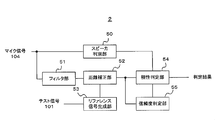
- FIG. 2 shows the internal configuration of the signal processing unit 2.
- the signal processing unit 2 includes a speaker determination unit 50, a filter unit 51, a distance correction unit 52, a reference signal generation unit 53, a polarity determination unit 54, and a reliability determination unit 55.
- the signal processing unit 2 is preferably constituted by a DSP (Digital Signal Processor) or the like.
- the microphone signal 104 output from the A / D converter 10 is input to the speaker discrimination unit 50 and the filter unit 51.
- the speaker discriminating unit 50 discriminates a plurality of types of speakers that are targets of polarity determination.
- the speaker discrimination unit 50 classifies the speakers 6 into an all-band type speaker and a middle / high range type speaker.
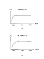
- FIG. 3A shows an example of frequency characteristics of the full-band type speaker
- FIG. 3B shows an example of frequency characteristics of the middle / high range type speaker.
- the full-band type speaker is a speaker that can reproduce from a low range to a high range.
- the mid / high range type speaker is a speaker that can reproduce from the mid range to the high range but has low reproduction capability in the low range. In the example of FIG.
- the mid / high range type speaker lacks the reproduction capability in a band of 200 Hz or less as compared with the full-band type speaker.
- the frequency band used in polarity determination described later is changed according to the type of speaker.
- a speaker discrimination unit 50 for discriminating the type of speaker is provided.
- the acoustic device 1 reproduces a low-frequency test signal and a middle-frequency test signal as test signals in a state where the speaker 6 to be discriminated is connected to the acoustic device 1, and acquires those microphone signals through the microphone 8.
- the frequency of the low-frequency test signal is approximately 200 Hz
- the frequency of the mid-frequency test signal is approximately 1 kHz.
- the low-frequency microphone signal and the mid-frequency microphone signal are supplied to the speaker discrimination unit 50 as the microphone signal 104.
- the speaker discrimination unit 50 compares the power of the low-frequency microphone signal with the power of the mid-range microphone signal. If the power of the low-frequency microphone signal is substantially equal to the power of the mid-range microphone signal, speaker determination unit 50 determines that the speaker is a full-band speaker. On the other hand, if the power of the low-frequency microphone signal is smaller than the power of the mid-range microphone signal, the speaker determination unit 50 determines that the speaker is a middle / high frequency speaker. The speaker determination unit 50 supplies the determination result obtained in this way to the polarity determination unit 54.
- bass reflex speakers are classified as full-band speakers.
- the bass reflex type speaker is characterized in that the phase of the reproduced signal is easily disturbed at a low frequency due to its structure.
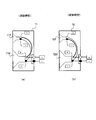
- FIG. 4A shows a multi-way speaker 71 including a tweeter 71T and a woofer 71W as a speaker unit.
- the woofer 71W and the tweeter 71T have a structure in which plus terminals and minus terminals are connected to each other. This is called “forward connection type” for convenience.
- FIG. 4 (b) there is a configuration such as a speaker 72 in which a woofer 72W and a tweeter 72T are connected in reverse polarity as shown in FIG.
- reverse connection type This is called “reverse connection type” for convenience.
- the phase of the low frequency signal reproduced from the woofer 72W and the phase of the middle / high frequency signal reproduced from the tweeter 72T are reversed.
- this embodiment has one feature in that the polarity is determined in consideration of the above-described all-band speaker.
- the filter unit 51 filters the microphone signal 104 to a predetermined frequency and supplies it to the distance correction unit 52.
- the filter unit 51 performs filtering with a 200 Hz LPF or a 500 Hz BPF.
- the reference signal generator 53 generates a reference signal from the test signal 101. Specifically, the reference signal generation unit 53 performs filtering on the test signal 101 with the same filter as the filtering performed by the filter unit 51 on the microphone signal 104 to generate a reference signal. That is, when the filter unit 51 filters the microphone signal 104 with a 200 Hz LPF (Low Pass Filter), the reference signal generation unit 53 generates the reference signal by filtering the test signal 101 with the 200 Hz LPF. This is supplied to the correction unit 52. When the filter unit 51 filters the microphone signal 104 with a 500 Hz BPF (Band Pass Filter), the reference signal generation unit 53 generates a reference signal by filtering the test signal 101 with a 500 Hz BPF. This is supplied to the correction unit 52.
- LPF Low Pass Filter
- the distance correction unit 52 corrects a signal delay corresponding to the distance between the speaker 6 and the microphone 8 arranged in the acoustic space 20.
- the microphone signal has a delay corresponding to the time required for the test sound to reach the microphone 8 from the speaker 6, that is, a delay time Td. included. This delay time Td is proportional to the distance between the speaker 6 and the microphone 8.
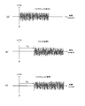
- Fig. 5 shows the distance correction method.
- the reference signal is generated by the reference signal generator 53.
- the head of the reference signal is shown in time 0 on the time axis.
- the microphone signal obtained from the microphone 8 has the above-described delay time Td. Therefore, as shown in FIG. 5C, the distance correction unit 52 delays the reference signal by the delay time Td in the microphone signal and matches the time axis of the reference signal with the time axis of the microphone signal, that is, the time axis. Make adjustments.
- the distance correction unit 52 measures the delay time Td prior to the distance correction and stores it in a storage unit (not shown).
- a method of reproducing a pulse test signal from the speaker 6 and collecting the sound with the microphone 8 and obtaining a time difference between the reproduction timing of the test signal and the timing of the pulse component in the microphone signal can be used.
- the distance correction unit 52 supplies the reference signal and the microphone signal after the adjustment on the time axis by the distance correction to the polarity determination unit 54.
- the polarity determination unit 54 determines the polarity of the speaker by comparing the reference signal and the microphone signal.
- the reference signal and microphone signal used here are those after the distance correction by the distance correction unit 52 as described above.
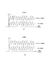
- FIG. 6A shows the phase relationship between the reference signal and the microphone signal when the speaker connection is in the normal phase
- FIG. 6B is the phase between the reference signal and the microphone signal when the speaker connection is in the opposite phase. Show the relationship.
- FIG. 6 schematically shows a waveform after the reference signal and the microphone signal are band-limited to a certain frequency.
- the phase of the reference signal and the phase of the microphone signal are in the positive phase (in phase).
- the speaker connection is in reverse phase
- the phase of the reference signal and the phase of the microphone signal are in reverse phase. Therefore, basically, by comparing the reference signal and the microphone signal and detecting the phase relationship between them, it is possible to determine whether the speaker connection is in the normal phase or the reverse phase.
- the polarity determination unit 54 determines that the speaker connection is in phase when the waveform of the signal after addition becomes larger than the waveform of one or both signals before addition, and the waveform of the signal after addition is added. If it becomes smaller than the waveform of one or both of the previous signals, it is determined that the speaker connection is in reverse phase.
- an addition signal obtained by adding the reference signal and the microphone signal and a subtraction signal obtained by subtracting the other from one of the reference signal and the microphone signal can be used, and the two can be compared.
- the amplitudes of the addition signal and the subtraction signal may be compared, or the respective powers may be calculated and compared.
- the polarity determination unit 54 determines that the speaker connection is in the normal phase if the addition signal is greater than the subtraction signal, and determines that the speaker connection is in the opposite phase if the addition signal is smaller than the subtraction signal.
- the filter unit 51 and the reference signal generation unit 53 perform filtering using the same filter.
- the reference signal generation unit 53 and the filter unit 51 perform filtering with a low frequency, for example, an LPF of 200 Hz in principle.
- the polarity determination unit 54 compares the microphone signal filtered with the 200 Hz LPF and the reference signal generated by filtering the test signal with the 200 Hz LPF.
- the reason for using a low frequency component of 200 Hz or less is as follows.
- the full-band type speakers targeted in this embodiment include a reverse connection type multi-way speaker as shown in FIG.
- the phase is inverted between the low range and the middle / high range.
- the boundary between the low frequency component and the middle / high frequency component is often around 160 Hz.
- such a reverse connection type multi-way speaker defines the polarity of the speaker on the basis of the low range. That is, as shown in FIG. 4B, a state where the woofer 72W is connected to the acoustic device 1 so as to be in a positive phase is considered as a correct connection state.
- the polarity determination unit 54 compares the reference signal generated by the 200 Hz LPF and the microphone signal filtered by the 200 Hz LPF. Thereby, about a reverse connection type multi-way speaker, polarity can be determined on the basis of a low region.
- the band may be limited to a frequency lower than 200 Hz for the purpose of determining the polarity with reference to the low band, but if the band is limited to a very low band, the frequency of the standing wave existing in the acoustic space 20 There is a possibility that the determination accuracy is lowered due to the influence of overlapping and the S / N being lowered. Therefore, in a preferred example of this embodiment, filtering is performed with an LPF of about 200 Hz.
- the frequency band used for polarity determination is preferably a low band of about 200 Hz as described above, but there are two exceptions.
- the first exception is when the speaker is a mid / high range speaker.
- the mid / high frequency type speaker lacks the low frequency component, so when the determination is made using the low frequency component of the reference signal and the microphone signal, the S / N cannot be secured. Accuracy is reduced. Therefore, for the middle / high frequency type speaker, the determination is performed using the middle frequency component of about 500 Hz.
- the polarity determination unit 54 compares the reference signal generated by filtering the test signal with a 500 Hz BPF and the microphone signal filtered with the 500 Hz BPF. This makes it possible to accurately determine the polarity of the middle / high range speaker that originally has a low range component.
- the second exception is a case where the reliability of the polarity determination result after band limiting with a 200 Hz LPF is low.
- the bass-band type speaker is included in the all-band type speaker targeted in this embodiment.
- bass reflex type speakers have signal reflection at the bass reflex port due to their structure, and therefore the phase of the low frequency component is often disturbed. Therefore, for bass reflex type speakers, the accuracy of polarity determination using a low frequency component may not be ensured. Therefore, in this embodiment, the reliability determination unit 55 determines the reliability of the polarity determination result obtained by using the low frequency component of 200 Hz or less, and when the reliability is low, the mid frequency component near 500 Hz is determined. Use again to determine polarity. As a result, accurate determination is possible even for a speaker in which the phase of the low frequency component is disturbed, such as a bass reflex speaker.
- the reliability determination unit 55 calculates and compares the power Pa of the addition signal of the reference signal and the microphone signal supplied from the distance correction unit 52 and the power Ps of both subtraction signals. As can be understood from FIG. 6, when there is no phase disturbance in the low frequency component, the power Pa of the addition signal is nearly doubled and the power Ps of the subtraction signal is close to 0 if the speaker connection is positive phase. On the other hand, if the speaker connection is in reverse phase, the power Pa of the addition signal is close to 0, and the power Ps of the subtraction signal is close to twice.
- the reliability determination unit 55 uses a low frequency component of 200 Hz or less.
- the reliability determination unit 55 performs the reliability determination, so that the polarity determination accuracy can be improved even for a speaker in which the phase of the low frequency component of the reproduction signal is disturbed, such as a bass reflex speaker. Become.
- the polarity determination is performed, but there is a reverse connection type multi-way speaker as shown in FIG. 4B on the market.
- the polarity determination is performed by comparing the microphone signal filtered with the 200 Hz LPF and the reference signal generated by filtering the test signal with the 200 Hz LPF. Note that the polarity determination based on the low frequency component does not cause any problem for the forward connection type multi-way speaker as shown in FIG. That is, the determination of the polarity of the speaker is based on the procedure of performing the distance correction using the high frequency component and then performing the polarity determination using the low frequency component.
- the speaker is first discriminated at the beginning of the processing, and the polarity is discriminated by using the middle band component exceptionally for the middle / high band type speaker. That is, the polarity is determined by comparing the microphone signal filtered with the 500 Hz BPF and the reference signal generated by filtering the test signal with the 500 Hz BPF.
- a speaker that has been identified as a low-frequency speaker may have a problem in determining polarity using a low-frequency component, such as the bass reflex type described above. Therefore, the reliability determination is performed, and when the reliability is low, the polarity determination is exceptionally performed using the mid-band component.
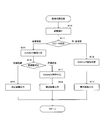
- FIG. 7 is a flowchart of the polarity determination process. The polarity determination process is executed by each component shown in FIG.
- the signal processing unit 2 outputs a test sound from the speaker 6, collects the sound with the microphone 8, and obtains a microphone signal.
- the distance correction unit 52 performs distance correction using the delay time Td measured in advance, and adjusts the time axis of the reference signal and the microphone signal (step S10).
- the speaker discrimination unit 50 compares the power of the low frequency component and the power of the mid frequency component to determine whether the currently connected speaker 6 is an all-band type speaker or a middle / high frequency type speaker. Is discriminated (step S11).
- the polarity determination unit 54 When it is determined that the currently connected speaker 6 is a middle / high-frequency speaker, the polarity determination unit 54 performs polarity determination using a mid-frequency component near 500 Hz (step S12). That is, the polarity determination unit 54 performs polarity determination by comparing the amplitude or power of the reference signal generated using the 500 Hz BPF and the microphone signal filtered by the 500 Hz BPF. And the polarity determination part 54 outputs the obtained determination result to the display part etc. of the audio equipment 1, etc., for example. Thereby, the user can know whether or not the speaker is correctly connected.
- the polarity determination unit 54 When it is determined in step S11 that the currently connected speaker is a full-band speaker, the polarity determination unit 54 first performs polarity determination using a low frequency component of 200 Hz or less (step S14). That is, the polarity determination unit 54 compares the reference signal generated using the 200 Hz LPF and the microphone signal filtered by the 200 Hz LPF, and obtains a polarity determination result. And the polarity determination part 54 hold
- the reliability determination unit 55 performs reliability determination using the same reference signal and microphone signal as those in step S14 (step S15). As described above, this reliability determination is to confirm whether or not the result of polarity determination using a low frequency component of 200 Hz or less is reliable. When it is determined that the reliability is high, the polarity determination unit 54 outputs the result of the polarity determination performed in step S14 (step S16). On the other hand, when it is determined that the reliability is low, the polarity determination unit 54 discards the determination result obtained in step S14 and newly performs polarity determination using a mid-frequency component near 500 Hz (step S17).
- the polarity is determined by comparing the reference signal generated using the 500 Hz BPF and the microphone signal filtered by the 500 Hz BPF. And the polarity determination part 54 outputs the obtained determination result (step S18). Thus, the polarity determination process ends.
- accurate polarity determination can be performed after correcting the propagation delay of the sound wave caused by the distance between the speaker and the microphone by the distance correction in step S10.
- step S11 speaker discrimination is performed in step S11, and for middle and high frequency speakers, polarity determination is performed using a mid frequency component in the vicinity of 500 Hz. Therefore, it is accurate even for mid and high frequency speakers that lack low frequency components. The polarity can be determined.
- the polarity determination since the polarity determination is first performed in the low frequency range of 200 Hz or less for the all-band type speaker, the polarity determination can be performed based on the low frequency component for the reverse connection type multi-way speaker. Furthermore, the reliability of the polarity determination is determined in the low frequency range, and when the reliability is low, the polarity determination is performed again using the middle frequency component near 500 Hz. Therefore, the determination accuracy can be improved even for a speaker whose phase of the low frequency component is disturbed, such as a bass reflex speaker.
- the reason why the reliability determination unit 55 determines that the reliability is low is not the case of the bass reflex type speaker in reality, for example, the influence of the group delay due to the network circuit of the speaker, the reflection from the wall in the acoustic space, etc. It is also possible that the speaker is not pointing correctly at the microphone. However, in any case, it can be expected that the determination accuracy is improved by performing the reliability determination, and when the reliability is low, the polarity determination is performed again using the mid-band component.
- the polarity determination of one speaker that is, one channel of an acoustic signal has been described.
- the actual audio device for example, a device that performs reproduction of a plurality of channels such as an audio reproduction device and an AV reproduction device is used, and a plurality of speakers are connected to the audio device 1.
- the above polarity determination process may be executed for each speaker.
- the delay time is measured by performing distance correction of a plurality of speakers when the acoustic device 1 is installed, the result can be stored and used for distance correction in the polarity determination processing.
- the polarity determination processing according to the present invention can be performed using the microphone signal acquired at that time. For example, when frequency characteristic correction is performed using pink noise as a test signal as automatic sound field correction, if the polarity determination processing is executed using the microphone signal obtained at that time, the acoustic characteristic correction The time required for the whole can be shortened.
- the speaker polarity determination device of the present invention can be used for home theater products, audio products, and the like, for example.
Landscapes
- Health & Medical Sciences (AREA)
- General Health & Medical Sciences (AREA)
- Otolaryngology (AREA)
- Physics & Mathematics (AREA)
- Engineering & Computer Science (AREA)
- Acoustics & Sound (AREA)
- Signal Processing (AREA)
- Circuit For Audible Band Transducer (AREA)
- Stereophonic System (AREA)
Abstract
Description
2 信号処理部
6 スピーカ
8 マイク
50 スピーカ判別部
51 フィルタ部
52 距離補正部
53 記憶部
54 極性判定部
55 信頼度判定部
図1に、本発明によるスピーカ極性判定装置を適用した音響装置1の概略構成を示す。音響装置1にはスピーカ6が接続され、CD、DVDなどの図示しない音響ソースからの音響信号がスピーカ6を通じて再生される。なお、以下に説明するスピーカ極性判定は、音響ソースからの再生に先だって、音響装置1に対してスピーカ6を接続したときに実行されるものである。
まず、極性判定処理の基本的な手順について説明する。スピーカの極性判定を行うにあたり、まず対象となるスピーカに対して距離補正が行われる。これは、スピーカの配置に応じた距離補正を行わなければ、マイク信号の位相が不定となり、極性判定が正しく行えないからである。距離補正は、上述のようにパルス性の信号、つまり高域の信号を用いて行われる。
上記の実施例では、1つのスピーカ、即ち音響信号の1チャンネルの極性判定について説明した。実際の音響装置1としては、例えば音響再生機器、AV再生機器など、複数チャンネルの再生を行う機器が用いられ、音響装置1に対して複数のスピーカが接続されることになる。その場合、基本的には上記の極性判定処理を1つずつのスピーカに対して実行すればよい。但し、その音響機器1の設置時に複数のスピーカの距離補正を行って遅延時間が測定される場合には、その結果を記憶しておき、極性判定処理における距離補正に使用することができる。また、音響装置1において周波数特性補正、遅延補正などの各種の自動音場補正が行われる場合には、その際に取得したマイク信号を利用して本発明による極性判定処理を行うことができる。例えば、自動音場補正として、テスト信号としてピンクノイズを使用して周波数特性補正が行われる場合には、その際に得られたマイク信号を利用して極性判定処理を実行すれば、音響特性補正全体に要する時間を短縮することができる。
Claims (7)
- スピーカが接続される出力端子と、
前記出力端子にテスト信号を供給し、前記スピーカを通じて音響空間にテスト音を出力するテスト音出力部と、
前記音響空間に配置され、前記テスト音を集音してマイク信号を生成するマイクと、
前記テスト信号に対応するリファレンス信号を生成する信号生成部と、
前記マイク信号と前記リファレンス信号の所定の周波数帯域成分を比較して、前記出力端子に接続されたスピーカの極性を判定する極性判定部と、を備えることを特徴とするスピーカ極性判定装置。 - 前記マイク信号に基づいて前記スピーカと前記マイクとの距離に対応する遅延時間を測定し、当該遅延時間に基づいて、前記極性判定部が使用するマイク信号とリファレンス信号との間の時間軸調整を行う距離補正部を備えることを特徴とする請求項1に記載のスピーカ極性判定装置。
- 前記マイク信号に基づいて、前記スピーカが全帯域型スピーカと中高域型スピーカのいずれであるかを判別するスピーカ判別部を備え、
前記スピーカが中高域型スピーカであると判別された場合、前記極性判定部は、前記マイク信号と前記リファレンス信号の中域成分を比較してスピーカの極性を判定することを特徴とする請求項1又は2に記載のスピーカ極性判定装置。 - 前記マイク信号と前記リファレンス信号に基づいて、前記極性判定部による判定結果の信頼度を判定する信頼度判定部を備え、
前記スピーカが全帯域型スピーカであると判別された場合、前記極性判定部は前記マイク信号と前記リファレンス信号の低域成分を比較してスピーカの極性を判定するとともに前記信頼度判定部は判定結果の信頼度を判定し、判定結果の信頼度が高いと前記信頼度判定部が判定した場合にのみ前記極性判定部は当該判定結果を出力することを特徴とする請求項1乃至3のいずれか一項に記載のスピーカ極性判定装置。 - 判定結果の信頼度が低いと前記信頼度判定部が判定した場合、前記極性判定部は、前記マイク信号と前記リファレンス信号の中域成分を比較してスピーカの極性を判定し、判定結果を出力することを特徴とする請求項4に記載のスピーカ極性判定装置。
- 前記信頼度判定部は、前記マイク信号と前記リファレンス信号の和信号のパワーと差信号のパワーを算出し、和信号のパワーと差信号のパワーとのパワー差が所定値以上である場合に判定結果の信頼度が高いと判定し、前記パワー差が前記所定値未満である場合に判定結果の信頼度が低いと判定することを特徴とする請求項1乃至5のいずれか一項に記載のスピーカ極性判定装置。
- 前記極性判定部は、前記マイク信号と前記リファレンス信号の和信号と差信号の振幅又はパワーを比較し、前記和信号が前記差信号より大きい場合には前記スピーカが正相に接続されていると判定し、前記和信号が前記差信号より小さい場合には前記スピーカが逆相に接続されていると判定することを特徴とする請求項1乃至6のいずれか一項に記載のスピーカ極性判定装置。
Priority Applications (3)
| Application Number | Priority Date | Filing Date | Title |
|---|---|---|---|
| US13/201,859 US8831235B2 (en) | 2009-02-26 | 2009-02-26 | Speaker polarity determination device |
| PCT/JP2009/053542 WO2010097924A1 (ja) | 2009-02-26 | 2009-02-26 | スピーカ極性判定装置 |
| JP2011501406A JP5286407B2 (ja) | 2009-02-26 | 2009-02-26 | スピーカ極性判定装置 |
Applications Claiming Priority (1)
| Application Number | Priority Date | Filing Date | Title |
|---|---|---|---|
| PCT/JP2009/053542 WO2010097924A1 (ja) | 2009-02-26 | 2009-02-26 | スピーカ極性判定装置 |
Publications (1)
| Publication Number | Publication Date |
|---|---|
| WO2010097924A1 true WO2010097924A1 (ja) | 2010-09-02 |
Family
ID=42665151
Family Applications (1)
| Application Number | Title | Priority Date | Filing Date |
|---|---|---|---|
| PCT/JP2009/053542 Ceased WO2010097924A1 (ja) | 2009-02-26 | 2009-02-26 | スピーカ極性判定装置 |
Country Status (3)
| Country | Link |
|---|---|
| US (1) | US8831235B2 (ja) |
| JP (1) | JP5286407B2 (ja) |
| WO (1) | WO2010097924A1 (ja) |
Cited By (1)
| Publication number | Priority date | Publication date | Assignee | Title |
|---|---|---|---|---|
| US11438696B2 (en) | 2020-03-27 | 2022-09-06 | Panasonic Intellectual Property Management Co., Ltd. | Active noise reduction device and active noise reduction method |
Families Citing this family (9)
| Publication number | Priority date | Publication date | Assignee | Title |
|---|---|---|---|---|
| US9412390B1 (en) * | 2010-04-12 | 2016-08-09 | Smule, Inc. | Automatic estimation of latency for synchronization of recordings in vocal capture applications |
| EP2949133B1 (en) * | 2013-01-24 | 2019-02-13 | Dolby Laboratories Licensing Corporation | Automatic loudspeaker polarity detection |
| US10284985B1 (en) | 2013-03-15 | 2019-05-07 | Smule, Inc. | Crowd-sourced device latency estimation for synchronization of recordings in vocal capture applications |
| US11146901B2 (en) | 2013-03-15 | 2021-10-12 | Smule, Inc. | Crowd-sourced device latency estimation for synchronization of recordings in vocal capture applications |
| EP2874408B1 (en) * | 2013-11-14 | 2016-05-25 | Nxp B.V. | Loudspeaker polarity detector |
| WO2020146728A1 (en) * | 2019-01-10 | 2020-07-16 | Parts Express International, Inc. | Measuring loudspeaker nonlinearity and asymmetry |
| US11153043B2 (en) * | 2019-10-24 | 2021-10-19 | Roku, Inc. | Measuring and evaluating a test signal generated by a device under test (DUT) |
| US11102596B2 (en) * | 2019-11-19 | 2021-08-24 | Roku, Inc. | In-sync digital waveform comparison to determine pass/fail results of a device under test (DUT) |
| CN119729326A (zh) * | 2023-09-27 | 2025-03-28 | 北京小米移动软件有限公司 | 喇叭极性检测方法、装置及存储介质 |
Citations (4)
| Publication number | Priority date | Publication date | Assignee | Title |
|---|---|---|---|---|
| JPS49106315A (ja) * | 1973-02-08 | 1974-10-08 | ||
| JP2002330500A (ja) * | 2001-04-27 | 2002-11-15 | Pioneer Electronic Corp | 自動音場補正装置及びそのためのコンピュータプログラム |
| JP2004297368A (ja) * | 2003-03-26 | 2004-10-21 | Yamaha Corp | アレイスピーカ検査装置、アレイスピーカ装置、及びこの装置の配線判定方法 |
| JP2008191315A (ja) * | 2007-02-02 | 2008-08-21 | Pioneer Electronic Corp | 音響装置、その方法、そのプログラム及びその記憶媒体 |
Family Cites Families (7)
| Publication number | Priority date | Publication date | Assignee | Title |
|---|---|---|---|---|
| JPH06311578A (ja) | 1993-04-19 | 1994-11-04 | Clarion Co Ltd | オーディオ装置におけるスピーカ極性判定方法 |
| JP3480636B2 (ja) | 1995-10-31 | 2003-12-22 | クラリオン株式会社 | オーディオ装置のスピーカ極性判定装置 |
| JP3286603B2 (ja) * | 1998-09-22 | 2002-05-27 | ヤマハ株式会社 | スピーカの極性判別回路、スピーカの極性判別機能を備えたオーディオ回路、スピーカの極性判別および極性切換機能を備えたオーディオ回路 |
| US6970568B1 (en) * | 1999-09-27 | 2005-11-29 | Electronic Engineering And Manufacturing Inc. | Apparatus and method for analyzing an electro-acoustic system |
| US20060050891A1 (en) * | 2004-09-07 | 2006-03-09 | Sunil Bharitkar | Method for automatic loudspeaker polarity determination through loudspeaker-room acoustic responses |
| US20060062399A1 (en) * | 2004-09-23 | 2006-03-23 | Mckee Cooper Joel C | Band-limited polarity detection |
| JP4240228B2 (ja) * | 2005-04-19 | 2009-03-18 | ソニー株式会社 | 音響装置、接続極性判定方法および接続極性判定プログラム |
-
2009
- 2009-02-26 US US13/201,859 patent/US8831235B2/en active Active
- 2009-02-26 JP JP2011501406A patent/JP5286407B2/ja active Active
- 2009-02-26 WO PCT/JP2009/053542 patent/WO2010097924A1/ja not_active Ceased
Patent Citations (4)
| Publication number | Priority date | Publication date | Assignee | Title |
|---|---|---|---|---|
| JPS49106315A (ja) * | 1973-02-08 | 1974-10-08 | ||
| JP2002330500A (ja) * | 2001-04-27 | 2002-11-15 | Pioneer Electronic Corp | 自動音場補正装置及びそのためのコンピュータプログラム |
| JP2004297368A (ja) * | 2003-03-26 | 2004-10-21 | Yamaha Corp | アレイスピーカ検査装置、アレイスピーカ装置、及びこの装置の配線判定方法 |
| JP2008191315A (ja) * | 2007-02-02 | 2008-08-21 | Pioneer Electronic Corp | 音響装置、その方法、そのプログラム及びその記憶媒体 |
Cited By (1)
| Publication number | Priority date | Publication date | Assignee | Title |
|---|---|---|---|---|
| US11438696B2 (en) | 2020-03-27 | 2022-09-06 | Panasonic Intellectual Property Management Co., Ltd. | Active noise reduction device and active noise reduction method |
Also Published As
| Publication number | Publication date |
|---|---|
| US20110299691A1 (en) | 2011-12-08 |
| JP5286407B2 (ja) | 2013-09-11 |
| US8831235B2 (en) | 2014-09-09 |
| JPWO2010097924A1 (ja) | 2012-08-30 |
Similar Documents
| Publication | Publication Date | Title |
|---|---|---|
| JP5286407B2 (ja) | スピーカ極性判定装置 | |
| US9848263B2 (en) | Enhancing audio using a mobile device | |
| US12081183B2 (en) | Customized automated audio tuning | |
| US7792310B2 (en) | Method and apparatus for automatically setting speaker mode in audio/video system | |
| US20090196440A1 (en) | Audio player apparatus and its control method | |
| US20110150230A1 (en) | Sound processing apparatus and method | |
| US12192737B2 (en) | Automated audio tuning and compensation procedure | |
| EP3122074B1 (en) | Audio-signal processing device, and audio-signal processing method | |
| JP4275848B2 (ja) | 音場計測装置および音場計測方法 | |
| JP2007509558A (ja) | 適応型音声再生 | |
| EP1592283A2 (en) | Measuring apparatus and method, and recording medium | |
| US12267655B2 (en) | Automated audio tuning launch procedure and report | |
| WO2023081534A1 (en) | Automated audio tuning launch procedure and report | |
| JP2006005902A (ja) | 増幅装置及び振幅周波数特性調整方法 | |
| JP2007043295A (ja) | 増幅装置及び振幅周波数特性調整方法 | |
| JP4435232B2 (ja) | オーディオシステム | |
| JP2005151404A (ja) | 信号遅延時間測定装置及びそのためのコンピュータプログラム | |
| JP6044365B2 (ja) | 信号補正装置、信号補正装置の制御方法及びプログラム | |
| JP6003680B2 (ja) | 信号補正装置、信号補正装置の制御方法及びプログラム | |
| JPH0847099A (ja) | スピ−カ遅延時間の設定方法 | |
| EP3506660A1 (en) | Method for calibrating an audio reproduction system and corresponding audio reproduction system |
Legal Events
| Date | Code | Title | Description |
|---|---|---|---|
| 121 | Ep: the epo has been informed by wipo that ep was designated in this application |
Ref document number: 09840777 Country of ref document: EP Kind code of ref document: A1 |
|
| WWE | Wipo information: entry into national phase |
Ref document number: 2011501406 Country of ref document: JP |
|
| WWE | Wipo information: entry into national phase |
Ref document number: 13201859 Country of ref document: US |
|
| NENP | Non-entry into the national phase |
Ref country code: DE |
|
| 122 | Ep: pct application non-entry in european phase |
Ref document number: 09840777 Country of ref document: EP Kind code of ref document: A1 |