WO2010095713A1 - 無線通信システム、無線通信装置および無線通信方法 - Google Patents
無線通信システム、無線通信装置および無線通信方法 Download PDFInfo
- Publication number
- WO2010095713A1 WO2010095713A1 PCT/JP2010/052542 JP2010052542W WO2010095713A1 WO 2010095713 A1 WO2010095713 A1 WO 2010095713A1 JP 2010052542 W JP2010052542 W JP 2010052542W WO 2010095713 A1 WO2010095713 A1 WO 2010095713A1
- Authority
- WO
- WIPO (PCT)
- Prior art keywords
- instruction signal
- wireless communication
- execution
- communication system
- operation instruction
- Prior art date
Links
Images


Classifications
-
- G—PHYSICS
- G05—CONTROLLING; REGULATING
- G05B—CONTROL OR REGULATING SYSTEMS IN GENERAL; FUNCTIONAL ELEMENTS OF SUCH SYSTEMS; MONITORING OR TESTING ARRANGEMENTS FOR SUCH SYSTEMS OR ELEMENTS
- G05B19/00—Programme-control systems
- G05B19/02—Programme-control systems electric
- G05B19/418—Total factory control, i.e. centrally controlling a plurality of machines, e.g. direct or distributed numerical control [DNC], flexible manufacturing systems [FMS], integrated manufacturing systems [IMS], computer integrated manufacturing [CIM]
- G05B19/4185—Total factory control, i.e. centrally controlling a plurality of machines, e.g. direct or distributed numerical control [DNC], flexible manufacturing systems [FMS], integrated manufacturing systems [IMS], computer integrated manufacturing [CIM] characterised by the network communication
- G05B19/4186—Total factory control, i.e. centrally controlling a plurality of machines, e.g. direct or distributed numerical control [DNC], flexible manufacturing systems [FMS], integrated manufacturing systems [IMS], computer integrated manufacturing [CIM] characterised by the network communication by protocol, e.g. MAP, TOP
-
- H—ELECTRICITY
- H04—ELECTRIC COMMUNICATION TECHNIQUE
- H04W—WIRELESS COMMUNICATION NETWORKS
- H04W84/00—Network topologies
- H04W84/18—Self-organising networks, e.g. ad-hoc networks or sensor networks
- H04W84/20—Master-slave selection or change arrangements
-
- Y—GENERAL TAGGING OF NEW TECHNOLOGICAL DEVELOPMENTS; GENERAL TAGGING OF CROSS-SECTIONAL TECHNOLOGIES SPANNING OVER SEVERAL SECTIONS OF THE IPC; TECHNICAL SUBJECTS COVERED BY FORMER USPC CROSS-REFERENCE ART COLLECTIONS [XRACs] AND DIGESTS
- Y02—TECHNOLOGIES OR APPLICATIONS FOR MITIGATION OR ADAPTATION AGAINST CLIMATE CHANGE
- Y02P—CLIMATE CHANGE MITIGATION TECHNOLOGIES IN THE PRODUCTION OR PROCESSING OF GOODS
- Y02P90/00—Enabling technologies with a potential contribution to greenhouse gas [GHG] emissions mitigation
- Y02P90/02—Total factory control, e.g. smart factories, flexible manufacturing systems [FMS] or integrated manufacturing systems [IMS]
Definitions
- the present invention relates to a wireless communication system, a wireless communication device, and a wireless communication method for operating a plurality of devices in a coordinated manner in a constant cycle.
- a plurality of devices and a plurality of networks exist.
- such an FA system includes devices such as sensors, robots, servomotors, and controllers for controlling the devices.
- an inter-controller network for sharing information between controllers
- an information network for sharing information between PCs (Personal Computer) and controllers
- real-time communication between devices
- a plurality of networks such as a field network intended to connect in a coordinated manner, and a servo network intended to perform high-speed and high-reliability communication and connect devices at high speed, are provided.
- Representative communication methods of information networks include Ethernet (registered trademark) / IP (Internet Protocol) and PROFInet, and representative communication methods of an inter-controller network include MELSECNET and FL-net.
- CC-Link Control & Communication Link
- Devicenet are representative communication methods of field networks
- SSCNET Server System Controller Network
- an industrial robot is taken as an example of an apparatus that constitutes an FA system.
- the industrial robot operates via a servo amplifier and a servomotor in accordance with a command instructed from a controller in order to perform expansion / contraction, bending / stretching, vertical movement, horizontal movement or turning movement.
- two or more servo amplifiers and servomotors are sequentially operated according to a predetermined procedure.
- the operation of a machine tool called a roll feeder will be described as an example of an industrial robot.
- the roll feeder moves the rolls mounted on the table forward while adjusting the speed of the feeder, and achieves drilling by lowering the punch at the point where the rolls stop.
- the controller takes instructions through servo amplifiers to the servomotors that drive the feeders for moving the rolls and the punches for making holes.
- highly accurate coordinated operation is required. Therefore, by synchronously communicating periodically between the controller and each servo amplifier and servo motor, simultaneous activation and cooperative operation among a plurality of highly accurate servos are realized. In order to realize highly accurate cooperation, it is necessary to perform highly reliable communication.
- Patent Document 1 is an abnormality detection method for wired communication.
- it can not be determined whether there is a momentary error in communication quality or a machine failure just by having no response. Therefore, there is a problem that it can not be applied to wireless communication in which instantaneous communication interruption occurs.
- the present invention has been made in view of the above, and it is an object of the present invention to provide a wireless communication system, a wireless communication device and a wireless communication method capable of performing highly reliable wireless communication in a control system for controlling equipment. I assume.
- the present invention is a wireless communication system including a master station and a slave station that performs a predetermined operation based on an operation instruction transmitted by the master station.
- the master station generates the operation instruction as a radio frame, and when there is a response to the operation instruction from all slave stations during a predetermined response waiting time,
- An execution instruction signal generation unit that generates and transmits an execution instruction signal that instructs execution of an operation corresponding to the operation instruction, and the slave station receives the execution instruction signal and performs predetermined reception processing Instruction signal reception processing means, the execution instruction signal reception processing means, when the execution instruction signal is received, an operation based on an operation instruction corresponding to the execution instruction signal It is executed, further characterized in that to wait for execution of the operation based on the operation instruction until it receives an execution instruction signal corresponding to the operation instruction.
- the master transmits the operation instruction to the slaves, and when responses from all the slaves are obtained within a predetermined time, the master instructs the execution of the operation corresponding to the operation instruction.
- the effect is that wireless communication with high certainty can be performed.
- FIG. 1 is a diagram showing a configuration example of a communication system according to a first embodiment of the present invention.
- FIG. 2 is a diagram showing an example of the FA system.
- FIG. 3 is a diagram showing the concept of the basic operation of the master-slave system assumed.
- FIG. 4 is a diagram showing the concept of an operation for performing wireless communication.
- FIG. 5 is a diagram showing an example of the functional configuration of the master.
- FIG. 6 is a diagram showing an example of a functional configuration of a slave.
- FIG. 7 is a diagram showing the concept of the transmission of an instruction from the master to the slave and the device operation.
- FIG. 8 is a diagram showing an example of an operation instruction including a transmission error.
- FIG. 9 is a diagram showing another example of an operation instruction including a transmission error.
- FIG. 1 is a diagram showing a configuration example of a communication system according to the present invention.
- the communication system of the present embodiment is composed of a master 1 and slaves 2 to 5 which are controlled devices of the master 1.
- the number of slaves 2 to 5 constituting the communication system of the present embodiment is not limited as long as there are a plurality of slaves. Also, the number of masters 1 may be one or more, and may be a plurality.
- the communication system of the present embodiment can be used, for example, as a system configuring a field network or servo network in a FA system.
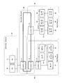
- FIG. 2 is a diagram showing an example of the FA system.
- the FA system shown in FIG. 2 includes PCs (Personal Computers) 10 and 11, controllers 12 to 15, sensors 16 and 17, a robot 18, and I / O devices (Input / Output) that perform information management of the FA system. 19, 20, servo amplifiers 21-23, and servomotors 24-26.
- the controllers 12 to 15 control the sensors 16 and 17, the robot 18, the I / O devices 19 and 20, and the servo amplifiers 21 to 23 according to predetermined programmed procedures, and the information from these devices is Perform acquisition etc. Further, the controllers 12 to 15 use the various positioning programs to perform advanced motion control such as synchronous operation, position tracking, tandem operation and the like to the servomotors 24 to 26 through the servo amplifiers 21 to 23.
- the sensors 16, 17 are controlled by the controller 15 to provide information to the controller 15.
- the robot 18 executes an operation based on a control instruction from the controller 15.
- the I / O devices 19 and 20 periodically input ON / OFF information and numerical information of each device based on a control instruction from the controller 15, or receive an input from an operator.
- the servo amplifiers 21 to 23 control the operations of the servomotors 24 to 26 connected to themselves based on the instruction from the controller 14.
- the servomotors 24 to 26 operate by driving the motor whose control amount is the position, the orientation, the posture, etc. of the object based on the instructions from the servo amplifiers 21 to 23 connected respectively.
- a detection mechanism is provided, the position, orientation, attitude, etc. are detected, and feedback is made to the connected servo amplifiers 21-23.
- the PCs 10 and 11 and the controller 12 constitute an information network N1 for sharing information
- the controllers 12 to 14 are controllers for sharing information among the controllers.
- An inter-network (Controller Network) N2 is configured.
- a field network for cooperatively connecting devices in real time by the controllers 13 and 15, the sensors 16 and 17, the robot 18 and the I / O devices 19 and 20 (Field Network)
- a servo network (Servo) for configuring N3 and performing communication with high speed and high reliability than the field network N3 by the controller 14, the servo amplifiers 21 to 23, and the servomotors 24 to 26, and connecting devices at high speed Network) constitutes N4.
- the sensors 16, 17, the robot 18, the I / O devices (Input / Output) 19, 20, the servo amplifiers 21 to 23, and the servomotors 24 to 26 cooperate to form one
- the FA system such as high precision position control aims The action can not be performed. Therefore, in the FA system, it is important to reliably transmit the operation instruction from the controllers 12-15.
- the communication system according to the present embodiment is premised on application to a system where certainty of transmission of an instruction from a master device is required as in the field network N2 and servo network N4 shown in FIG.
- the communication system shown in FIG. 1 corresponds to the field network N2 and the servo network N4 shown in FIG. 2, and devices serving as masters (controllers 13 to 15) and devices serving as slaves (sensors 15, 16, and The robot 18, I / O devices 19 and 20, servo amplifiers 21 to 23, servomotors 24 to 26, etc.), and a master controls the operation of a slave.
- FIG. 3 is a diagram showing the concept of the basic operation of the master-slave system on which the present embodiment is premised.
- the master issues instructions to each slave in a fixed cycle.
- each slave receives the instruction, it performs an operation based on the instruction in the next cycle (the cycle next to the cycle instructed by the master).
- the slave executes an operation based on the operation instruction # 1 received in the previous cycle.
- the master transmits the operation instruction # 3
- the slaves 2 to 5 execute the operation based on the operation instruction # 2.
- the slave performs the operation on the basis of the instruction from the master, thereby realizing the slave cooperative operation as a whole system.
- FIG. 3 is mainly a basic operation in the case of wired communication, but in this embodiment, this basic operation is applied to the case of wireless communication.
- FIG. 4 is a diagram showing the concept of the operation of the present embodiment for performing wireless communication.
- the wireless messages M1 to M5 are wireless messages transmitted and received between the master 1 and the slaves 2 to 5, and the wireless messages M1, M3, and M5 are messages transmitted from the master 1 to the slaves 2 to 5, and the wireless messages M 2 and M 4 are messages transmitted from slaves 2 to 5 to master 1.
- An operation A1 indicates an operation performed by the slaves 2 to 5.
- the wireless message M1 is a message for notifying the contents of the operation instruction from the master 1 to the slaves 2 to 5. Further, the wireless message M2 is a message notifying that the slaves 2 to 5 that have received the wireless message M1 have each received the content of the operation instruction to the master 1. If the slaves 2 to 5 can not receive the wireless message M1 correctly because of a communication error, the wireless message M2 which is a response to the wireless message M1 will not be returned. Also, transmission errors may occur when the slaves 2 to 5 transmit the wireless message M2.
- the wireless message M3 is a message for resending the operation instruction to the slave (non-responding slave) which did not correctly return the response to the wireless message M1 to the master.
- the wireless message M4 is a message transmitted by the non-responding slave as a response to the wireless message M3 when the wireless message M3 is received. It is also assumed that transmission errors occur during the transmission of the radio message M3 or the radio message M4. In such a case, retransmission may be repeated.
- transmission and retransmission of the operation instruction from the master 1 as described above are performed within a fixed cycle. Then, when there is a slave that has not received a response to the operation instruction, including a response to the retransmission, within the cycle of transmitting the operation instruction, the master 1 instructs all slaves 2 to 5 to wait for the operation. Send message M5. Then, when a standby instruction is issued, the standby operation instruction is retransmitted in the next cycle. Further, if responses to the operation instruction are obtained from all the slaves including the response to the retransmission within the cycle of transmitting the operation instruction, the master 1 instructs the operation execution by the wireless message M5.
- each of the slaves 2 to 5 carries out operation execution or standby (standby without executing the operation instructed by the wireless message M1 or the retransmission message thereof) based on the wireless message M5.
- the content of the operation to be executed at this time is the content notified by the wireless message M1 or its retransmission message.
- each slave 2 to 5 stands by when it can not receive the wireless message M 5, that is, when neither instruction for operation execution nor instruction for standby is received.
- the wireless messages M1 to M4 constitute a general wireless frame such as a wireless LAN (Local Area Network) or a mobile phone. Therefore, in order to communicate, reception SNR (Singnal to Noise Ratio) more than a fixed level is required.
- the radio message M5 may be a radio signal sequence (0 or 1 signal) indicating either operation execution or standby, so 20 to 30 dB as compared with the reception SNR required by the radio messages M1 to M4. It is generated as a receivable message even if it is low.
- the present invention is not limited to this.
- radio message M5 For the radio message M5, reliability is improved by repeatedly transmitting a normal radio frame, increasing transmission power, using a plurality of antennas, enhancing a low modulation scheme and error correction capability. May be sent.
- these methods may be combined to improve reliability and to transmit.
- FIG. 5 is a diagram showing an example of a functional configuration of the master 1 according to the present embodiment.
- the master 1 generates instructions and information to the slaves 2 to 5 and generates an application unit (master) 101 that extracts information from the slaves 2 to 5 and an application unit (master) 101.
- the radio signal processing unit 102 generates a transmission signal based on the instructions and information, and performs reception processing on the radio signals transmitted by the slaves 2 to 5, and an RF (Radio Frequency) unit (transmission and reception of radio signals) And the antenna unit 103).
- RF Radio Frequency
- the wireless signal processing unit 102 includes a transmission / reception control unit 104 that controls transmission / reception timing, a transmission unit 105 that generates a transmission signal based on an instruction or information generated by the application unit 101, and a reception unit that processes a reception signal. And 106. Also, the transmitting unit 105 generates a normal wireless frame for transmitting a message based on the instruction or information generated by the application unit 101, and instructs the slaves 2 to 5 to operate.
- the Go / Stop signal processing unit 108 generates a Stop signal indicating a signal or a standby.
- the reception unit 106 performs predetermined reception processing on a reception signal that is a radio signal received by the RF unit 103, performs reception processing as reception data, and passes the reception data to the transmission / reception control unit 104. Also, the receiving unit 106 controls the RF unit 103 such as increase / decrease of received power, frequency switching, switching to reception of an antenna, and the like.
- the transmission / reception control unit 104 determines an instruction to the slaves 2 to 5 and a start timing for sending information, notifies control information such as a destination address to the transmission unit 105, and is generated by the application unit (master) 101. The instruction and information are sent to the transmitting unit 105. This instruction includes an instruction to transmit either operation execution or standby in the wireless message M5.
- the transmission / reception control unit 104 also passes received data to the application unit (master) 101.
- the application unit (master) 101 determines whether to transmit the operation execution or the standby by the wireless message M5 by determining whether there is an unacknowledged slave on a periodic basis based on the received data. As described above, after transmitting the operation instruction in one cycle, if there is an unacknowledged slave, try retransmission, and if there is a slave that does not respond to retransmission, assume that there is an unacknowledged slave judge. If there is no unanswered slave, the operation execution is instructed by the wireless message M5, and if there is an unanswered slave, it is decided to indicate standby by the wireless message M5.
- the normal frame processing unit 107 determines based on the information and instructions.
- a radio frame is created and passed to the RF unit 103 as a transmission signal.
- This normal radio frame is a single carrier Time Division Duplex (TDD) or Frequency Division Duplex (FDD) frame such as a personal digital cellular (PDC), a personal handy-phone system (PHS), or a dedicated short range communication (DSRC).
- TDD Time Division Duplex
- FDD Frequency Division Duplex
- PDC personal digital cellular
- PHS personal handy-phone system
- DSRC dedicated short range communication
- OFDM Orthogonal Frequency Division Multiplexing
- WiMax Worldwide Interoperability for Microwave Access
- CSMA Carrier Sense Multiple Access
- OFDMA Orthogonal Frequency Division Multiplexing Access
- TDD Time Division Duplex
- FDD frame Frequency Division Multiplexing Access
- a normal radio frame may have an address structure for specifying the other party, and may be a frame configuration to which advanced modulation processing has been performed for efficient transmission.
- the Go / Stop signal processing unit 108 When the transmission / reception control unit 104 receives an instruction to transmit either operation execution (Go) or standby (Stop) as the wireless message M5, the Go / Stop signal processing unit 108 performs wireless communication based on the instruction. It generates a transmission signal for the message M5 and passes it to the RF unit 103.
- the transmission signal for the radio message M5 does not have to increase the transmission efficiency of information because the number of bits to be transmitted is small, but it is generated as a signal resistant to noise and interference signals.
- the signal is generated as a spread spectrum (SS) signal such as direct spreading DS (Direct Sequence) or frequency hopping (FH).
- the transmission unit 105 also controls the RF unit 103 such as increase / decrease of transmission power, frequency switching, switching to transmission of an antenna, and the like.
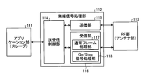
- FIG. 6 is a diagram showing an example of a functional configuration of the slaves 2 to 5 according to the present embodiment.
- slaves 2 to 5 each execute an operation upon receiving an instruction or information from master 1, or an application unit (slave) 111 that collects information to be transmitted to master 1 and the like.
- the information collecting unit 111 converts information collected by the application unit (slave) 111 into a transmission signal, and further includes a radio signal processing unit 112 that performs predetermined transmission and reception, and an RF unit (antenna unit) 113.
- the wireless signal processing unit 112 further includes a transmission / reception control unit 114 that controls transmission / reception timing, a transmission unit 115 that generates a transmission signal, and a reception unit 116 that processes a reception signal.
- the receiving unit 116 is a normal frame processing unit 117 that processes a normal frame including a message, and a Go / Stop signal processing unit that processes a Go signal that instructs the slave to operate or a Stop signal that instructs standby. And 118.
- the RF unit 113 receives the received wireless signal transmitted from the master 1 and passes it to the receiving unit 116, and transmits the transmission signal generated by the transmitting unit 115 as a wireless signal.
- the reception signal received from the RF unit 113 is a normal wireless frame
- the reception unit 116 performs a predetermined reception process on the reception signal and sets the reception data as a reception data
- the reception data is a transmission / reception control unit. Pass to 114.
- the received signal received from the RF unit 113 is the wireless message M5
- the Go / Stop signal processing unit 118 performs a predetermined reception process corresponding to the message and performs an operation based on the message.
- the application unit (slave) 111 when the instruction of the wireless message M5 is operation execution, the application unit (slave) 111 is instructed to execute the operation via the transmission / reception control unit 114, and the instruction of the wireless message M5 is standby. Instructs the application unit (slave) 111 to wait via the transmission / reception control unit 114. In addition, the reception unit 116 instructs the RF unit 113 to increase / decrease the reception power, switch the frequency, and switch the reception of the antenna.
- the transmission / reception control unit 114 instructs the transmission unit 115 to control information such as the start timing for sending a response or information from the own apparatus to the master 1 and the other party address, and instructs the reception unit 116 to start reception. To direct. Further, the transmission / reception control unit 114 receives the received data and the instruction to execute or wait for the operation from the reception unit 116, passes it to the application unit (slave) 111, and transmits the instruction and information generated by the application unit (slave) 11 to the transmission unit 115. hand over.
- the application unit (slave) 111 performs predetermined processing based on the instruction and information transmitted from the application unit (master) 101 of the master 1 received via the transmission / reception control unit 114, and transmits the data to the master 1. Generate instructions, information.
- the transmission unit 115 creates a wireless frame based on the instruction and information received from the transmission / reception control unit 114, and passes it to the RF unit 113 as a transmission signal. In addition, the transmission unit 115 instructs the RF unit 113 to increase / decrease transmission / transmission power, to switch the frequency, and to switch to transmission of the antenna.
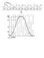
- FIG. 7 is a diagram showing the concept of the transmission of an instruction from the master 1 to the slaves 2 to 5 and the device operation.
- the cycle in which the operation instruction is transmitted from the master 1 is 0.44 ms.
- an instruction for the position of the motor is indicated numerically as the operation instruction, and numerical values such as "6", "20", "45",... In FIG. 7 are examples of this instruction.
- the graph in the lower part of FIG. 7 shows the position of the motor driven every 0.44 ms. For example, when "6" is instructed by the operation instruction in the upper diagram of FIG.
- FIG. 7 shows an example in the case where no transmission error occurs in the cycle (when the operation execution is instructed by the wireless message M5).
- FIG. 8 is a diagram showing an example of an operation instruction including a transmission error.
- the example of FIG. 8 is an example of performing the same operation as that of FIG. In this case, by performing the operation of the present embodiment as described above, a standby is instructed by the wireless message M5. Then, the operation instruction for instructing the position "45" of the motor is retransmitted in the next cycle.
- the example of FIG. 8 shows the case where transmission is normally performed in the next waiting cycle.
- FIG. 9 is a diagram showing another example of an operation instruction including a transmission error.
- a transmission error of the wireless section occurs in the operation instruction for instructing the position "96" of the motor.
- an operation indication instructing the motor position "100" is transmitted. ing.
- an operation instruction to be notified in the next cycle may be transmitted in that cycle, and the communication band may be effectively used.
- the present invention is not limited to this.
- the wireless message M5 described in the embodiment may be transmitted.
- a predetermined response waiting time is determined, and after transmitting the operation instruction, within the response waiting time
- the wireless message M5 may be transmitted based on whether or not there is a response (retransmission response) from the slave.
- an operation standby time when the slave waits for operation is also determined in advance.
- the master 1 transmits an operation instruction to the slaves 2 to 5 at a predetermined cycle, and if there is a slave without a response, the master 1 performs retransmission within the same cycle, and the cycle
- all slaves are instructed to wait for the operation.
- response are obtained from all slaves within a cycle, operation execution is instructed. Therefore, even when the communication between the master 1 and the slaves 2 to 5 is wireless communication, high reliability can be realized, and instructions can be reliably given to a plurality of slaves.
- normal communication data is generated as a signal with high transmission efficiency, and a message instructing operation standby or operation execution is generated as a signal resistant to noise or interference signals, or the message is retransmitted.
- noise and interference signals are tolerant. Therefore, high transmission efficiency can be realized, and high reliability can be realized.
- the wireless communication system, the wireless communication device, and the wireless communication method according to the present invention are useful for a system in which a plurality of devices controlled by a controller operate emphasizing, and in particular, to a system used in a FA environment. Is suitable.
Abstract
Description
図1は、本発明にかかる通信システムの構成例を示す図である。図1に示すように、本実施の形態の通信システムは、マスター(Master)1と、マスター1の被制御装置であるスレーブ(Slave)2~5と、で構成される。なお、本実施の形態の通信システムを構成するスレーブ2~5は、複数台であれば台数に制約はない。また、マスター1の台数は1台以上であればよく、複数台としてもよい。
2~5 スレーブ
10,11 PC
12~15 コントローラ
16,17 センサー
18 ロボット
19,20 I/Oデバイス
21~23 サーボアンプ
24~26 サーボモータ
101 アプリケーション部(マスター)
102,112 無線信号処理部
103,113 RF部
104,114 送受信制御部
105,115 送信部
106,116 受信部
107,117 通常フレーム処理部
108,118 Go/Stop信号処理部
111 アプリケーション部(スレーブ)
A1 動作
M1~M5 無線メッセージ
N1 Information Network
N2 Controller Network
N3 Field Network
N4 Servo Network
Claims (17)
- マスター局と、前記マスター局が送信する動作指示に基づいて所定の動作を実施するスレーブ局と、で構成される無線通信システムであって、
前記マスター局は、
前記動作指示を無線フレームとして生成する通常フレーム送信処理手段と、
所定の応答待機時間の間に全てのスレーブ局から前記動作指示に対する応答があった場合に、その動作指示に対応する動作の実行を指示する実行指示信号を生成して送信する実行指示信号作成手段と、
を備え、
前記スレーブ局は、
前記実行指示信号を受信し、所定の受信処理を行う実行指示信号受信処理手段、
を備え、
前記実行指示信号受信処理手段は、前記実行指示信号を受信した場合に、その実行指示信号に対応する動作指示に基づく動作を実行し、また、動作指示に対応する実行指示信号を受信するまでその動作指示に基づく動作の実行を待機することを特徴とする無線通信システム。 - 前記実行指示信号を、前記通常フレーム送信処理手段が無線フレームを生成する方式より要求受信SNRが低い方式で生成することを特徴とする請求項1に記載の無線通信システム。
- 前記実行指示信号を生成する方式を、その方式の要求SNRが、前記通常フレーム送信処理手段が無線フレームを生成する方式の要求SNRに比べ、20dB以上30dB以下の範囲で低い方式、とすることを特徴とする請求項2に記載の無線通信システム。
- 前記実行指示信号作成手段は、前記実行指示信号を所定の回数にわたって繰り返し送信することを特徴とする請求項1、2または3に記載の無線通信システム。
- 前記実行指示信号作成手段は、前記実行指示信号を送信する場合、前記通常フレーム送信処理手段が生成した通常フレームを送信する場合より、送信電力を高くすることを特徴とする請求項1~4のいずれか1つに記載の無線通信システム。
- 前記実行指示信号作成手段は、前記応答待機時間の間に1つ以上のスレーブ局から前記動作指示に対する応答が無い場合に、動作の待機を指示する待機指示信号をすべてのスレーブ局に対して送信し、
前記実行指示信号受信処理手段は、前記待機指示信号を受信した場合、所定の動作待機時間の間、その待機指示信号に対応する動作指示に基づく動作の実行を待機することを特徴とする請求項1に記載の無線通信システム。 - 前記待機指示信号を、前記通常フレーム送信処理手段が無線フレームを生成する方式より要求受信SNRが低い方式で生成することを特徴とする請求項6に記載の無線通信システム。
- 前記待機指示信号を生成する方式を、その方式の要求SNRが、前記通常フレーム送信処理手段が無線フレームを生成する方式の要求SNRに比べ、20dB以上30dB以下の範囲で低い方式、とすることを特徴とする請求項7に記載の無線通信システム。
- 前記実行指示信号作成手段は、前記待機指示信号を所定の回数にわたって繰り返し送信することを特徴とする請求項6、7または8に記載の無線通信システム。
- 前記実行指示信号作成手段は、前記待機指示信号を送信する場合、前記通常フレーム送信処理手段が生成した通常フレームを送信する場合より、送信電力を高くすることを特徴とする請求項6~9のいずれか1つに記載の無線通信システム。
- 前記通常フレーム送信処理手段は、前記動作指示に対する応答が1つ以上のスレーブ局から得られない場合には、応答が得られないスレーブ局へその動作指示を再送することを特徴とする請求項1~10のいずれか1つに記載の無線通信システム。
- 前記通常フレーム送信処理手段は、前記動作指示を所定の送信周期ごとに送信し、
前記応答待機時間を前記送信周期以内とすることを特徴とする請求項1~11のいずれか1つに記載の無線通信システム。 - 前記応答待機時間の間に1つ以上のスレーブ局から前記動作指示に対する応答が無い場合に、前記通常フレーム送信処理手段は、次の動作指示の送信時に、応答が得られなかった動作指示と同様の動作を指示する動作指示を送信することを特徴とする請求項1~12のいずれか1つに記載の無線通信システム。
- 前記応答待機時間の間に1つ以上のスレーブ局から前記動作指示に対する応答が無い場合に、前記通常フレーム送信処理手段は、次の動作指示の送信時に、応答が得られなかった動作指示の次の動作を指示する動作指示を送信することを特徴とする請求項1~12のいずれか1つに記載の無線通信システム。
- マスター局と、前記マスター局が送信する動作指示に基づいて所定の動作を実施するスレーブ局と、で構成される無線通信システムにおいて、前記マスター局として動作する無線通信装置であって、
前記動作指示を無線フレームとして生成する通常フレーム送信処理手段と、
所定の応答待機時間の間に全てのスレーブ局から前記動作指示に対する応答があった場合に、動作の実行を指示する実行指示信号を生成して送信する実行指示信号作成手段と、
を備えることを特徴とする無線通信装置。 - マスター局と、前記マスター局が送信する動作指示に基づいて所定の動作を実施するスレーブ局と、で構成される無線通信システムにおいて、前記スレーブ局として動作する無線通信装置であって、
前記マスター局から動作の実行を指示する実行指示信号を受信し、所定の受信処理を行う実行指示信号受信処理手段、
を備え、
前記実行指示信号受信処理手段は、前記実行指示信号を受信した場合に、その実行指示信号に対応する動作指示の内容を実行し、また、動作指示に対応する実行指示信号を受信するまでその動作指示に基づく動作の実行を待機することを特徴とする無線通信装置。 - マスター局と、前記マスター局が送信する動作指示に基づいて所定の動作を実施するスレーブ局と、で構成される無線通信システムにおける無線通信方法であって、
前記マスター局が、前記動作指示を無線フレームとして生成する通常フレーム送信処理ステップと、
前記マスター局が、所定の応答待機時間の間に全てのスレーブ局から前記動作指示に対する応答があった場合に、動作の実行を指示する実行指示信号を生成して送信する実行指示信号作成ステップと、
前記スレーブ局が、前記実行指示信号を受信した場合に、その実行指示信号に対応する動作指示の内容を実行し、また、動作指示に対応する実行指示信号を受信するまでその動作指示に基づく動作の実行を待機する実行指示信号受信処理ステップと、
を含むことを特徴とする無線通信方法。
Priority Applications (4)
| Application Number | Priority Date | Filing Date | Title |
|---|---|---|---|
| EP10743838.4A EP2400778B1 (en) | 2009-02-23 | 2010-02-19 | Wireless communication system, wireless communication device, and wireless communication method |
| JP2011500659A JP5497730B2 (ja) | 2009-02-23 | 2010-02-19 | 無線通信システム、無線通信装置および無線通信方法 |
| US13/202,771 US8676239B2 (en) | 2009-02-23 | 2010-02-19 | Wireless communication system, wireless communication device, and wireless communication method |
| CN201080008772.XA CN102326409B (zh) | 2009-02-23 | 2010-02-19 | 无线通信系统、无线通信装置以及无线通信方法 |
Applications Claiming Priority (2)
| Application Number | Priority Date | Filing Date | Title |
|---|---|---|---|
| JP2009-039858 | 2009-02-23 | ||
| JP2009039858 | 2009-02-23 |
Publications (1)
| Publication Number | Publication Date |
|---|---|
| WO2010095713A1 true WO2010095713A1 (ja) | 2010-08-26 |
Family
ID=42633991
Family Applications (1)
| Application Number | Title | Priority Date | Filing Date |
|---|---|---|---|
| PCT/JP2010/052542 WO2010095713A1 (ja) | 2009-02-23 | 2010-02-19 | 無線通信システム、無線通信装置および無線通信方法 |
Country Status (5)
| Country | Link |
|---|---|
| US (1) | US8676239B2 (ja) |
| EP (1) | EP2400778B1 (ja) |
| JP (1) | JP5497730B2 (ja) |
| CN (1) | CN102326409B (ja) |
| WO (1) | WO2010095713A1 (ja) |
Cited By (7)
| Publication number | Priority date | Publication date | Assignee | Title |
|---|---|---|---|---|
| JP2014165829A (ja) * | 2013-02-27 | 2014-09-08 | Mitsubishi Electric Corp | 無線通信装置 |
| JP2015518620A (ja) * | 2012-05-03 | 2015-07-02 | ブリストル, インコーポレイテッド, ディー/ビー/エー リモート オートメイテッド ソリューションズ | 無線通信プロトコルインタフェースを有するフロー計算機及び関連する方法 |
| DE102016008867A1 (de) | 2015-07-27 | 2017-02-02 | Fanuc Corporation | Echtzeit-Störungsprüfungssystem einer Werkzeugmaschine und eines Roboters |
| JP2017092856A (ja) * | 2015-11-16 | 2017-05-25 | 株式会社デンソー | 通信装置および通信システム |
| JP2017188868A (ja) * | 2016-04-04 | 2017-10-12 | Smc株式会社 | 産業用無線通信システム |
| JP2018083235A (ja) * | 2016-11-21 | 2018-05-31 | セイコーエプソン株式会社 | ロボット、及びロボットシステム |
| WO2019117249A1 (ja) * | 2017-12-13 | 2019-06-20 | 株式会社 Preferred Networks | 制御装置、制御方法及びプログラム |
Families Citing this family (7)
| Publication number | Priority date | Publication date | Assignee | Title |
|---|---|---|---|---|
| US8661171B1 (en) * | 2010-06-07 | 2014-02-25 | Qualcomm Incorporated | Host-slave interface for wireless communication circuit |
| DE102015117937B3 (de) | 2015-10-21 | 2017-01-19 | Beckhoff Automation Gmbh | Kommunikationsnetzwerk, Verfahren zum Betreiben eines solchen und Teilnehmer in einem Kommunikationsnetzwerk |
| US11518043B2 (en) * | 2018-12-20 | 2022-12-06 | Canon Kabushiki Kaisha | Communication apparatus, communication method, robot apparatus, production apparatus, method of manufacturing article, transmission apparatus, recording medium |
| JP6849769B2 (ja) * | 2018-12-20 | 2021-03-31 | キヤノン株式会社 | 通信装置、通信方法、ロボット装置、生産装置、物品の製造方法、送信装置、制御プログラム及び記録媒体 |
| DE112019006945T5 (de) * | 2019-04-05 | 2021-12-09 | Mitsubishi Electric Corporation | Mehrachssteuerungssystem, Mehrachssteuerungsverfahren und Mehrachssteuerungsprogramm |
| JPWO2022158015A1 (ja) | 2021-01-25 | 2022-07-28 | ||
| JP2022178977A (ja) | 2021-05-21 | 2022-12-02 | Smc株式会社 | ベース無線装置及び無線通信方法 |
Citations (4)
| Publication number | Priority date | Publication date | Assignee | Title |
|---|---|---|---|---|
| JPS60119195A (ja) * | 1983-11-30 | 1985-06-26 | Noritsu Co Ltd | 無線式遠隔制御方法 |
| JPS6354280B2 (ja) * | 1981-08-03 | 1988-10-27 | Tokyo Denryoku Kk | |
| JP2003273876A (ja) * | 2002-03-15 | 2003-09-26 | Matsushita Electric Ind Co Ltd | 制御装置、被制御装置、局所制御装置及び制御システム |
| JP2007312043A (ja) | 2006-05-17 | 2007-11-29 | Omron Corp | リモートi/oシステム |
Family Cites Families (20)
| Publication number | Priority date | Publication date | Assignee | Title |
|---|---|---|---|---|
| JPS6354280A (ja) | 1986-08-26 | 1988-03-08 | Ricoh Co Ltd | 感熱記録材料 |
| JPS63224499A (ja) * | 1987-03-13 | 1988-09-19 | Yasui Seiki:Kk | 遠隔操作方法およびその装置 |
| JPH05266395A (ja) | 1992-03-24 | 1993-10-15 | Omron Corp | 信号制御機 |
| JPH08106306A (ja) * | 1994-10-06 | 1996-04-23 | Meidensha Corp | データ伝送装置 |
| JP3436593B2 (ja) * | 1994-10-19 | 2003-08-11 | 富士通テン株式会社 | データ通信装置 |
| JP3634379B2 (ja) * | 1996-01-24 | 2005-03-30 | サン・マイクロシステムズ・インコーポレイテッド | スタックキャッシングのための方法及び装置 |
| JPH11167406A (ja) * | 1997-12-03 | 1999-06-22 | Olympus Optical Co Ltd | 分散制御システム及び分散制御システムの制御方法 |
| JP2000308259A (ja) | 1999-04-20 | 2000-11-02 | Toshiba Corp | 電力系統監視制御システム及びそのシステムの処理プログラムを記憶する記憶媒体 |
| US6496496B1 (en) * | 1999-04-22 | 2002-12-17 | Nortel Networks Limited | Crucial control message transmission method and systems |
| GB0015621D0 (en) * | 2000-06-27 | 2000-08-16 | Koninkl Philips Electronics Nv | Multicast radio communication system and apparatus |
| US6785748B2 (en) * | 2000-07-18 | 2004-08-31 | Canon Kabushiki Kaisha | Image communication apparatus wirelessly connectable to other apparatuses, system having the image communication apparatus, and method for controlling the same |
| WO2003001307A1 (fr) * | 2001-06-22 | 2003-01-03 | Omron Corporation | Systeme de reseau de securite, esclave de securite, et procede de communication |
| WO2003003659A1 (fr) * | 2001-06-27 | 2003-01-09 | Sony Corporation | Dispositif et procede, en controle de radiocommunications, support d'informations, et programme |
| JP3988559B2 (ja) * | 2002-07-18 | 2007-10-10 | オムロン株式会社 | 通信システム、通信装置及び通信制御方法 |
| JP2004289711A (ja) * | 2003-03-25 | 2004-10-14 | Toshiba Corp | 送信装置及び受信装置 |
| DE102005022989A1 (de) * | 2005-05-19 | 2006-11-23 | Drägerwerk AG | Modulares System und Verfahren zur Gewinnung und funkgestützten Weiterleitung von Messdaten |
| US8730867B2 (en) * | 2007-02-05 | 2014-05-20 | Thomson Licensing | Clock synchronization aid device for communication station(s) of a wireless network, and associated clock synchronization device |
| JP2009020547A (ja) | 2007-07-10 | 2009-01-29 | Yaskawa Electric Corp | 分散型モーション制御システム |
| US20090273489A1 (en) * | 2008-05-02 | 2009-11-05 | Jeffery Khuong Lu | System and method for transportation vehicle tracking |
| US7787981B2 (en) * | 2008-05-16 | 2010-08-31 | Xerox Corporation | System for reliable collaborative assembly and maintenance of complex systems |
-
2010
- 2010-02-19 EP EP10743838.4A patent/EP2400778B1/en active Active
- 2010-02-19 JP JP2011500659A patent/JP5497730B2/ja active Active
- 2010-02-19 US US13/202,771 patent/US8676239B2/en active Active
- 2010-02-19 CN CN201080008772.XA patent/CN102326409B/zh active Active
- 2010-02-19 WO PCT/JP2010/052542 patent/WO2010095713A1/ja active Application Filing
Patent Citations (4)
| Publication number | Priority date | Publication date | Assignee | Title |
|---|---|---|---|---|
| JPS6354280B2 (ja) * | 1981-08-03 | 1988-10-27 | Tokyo Denryoku Kk | |
| JPS60119195A (ja) * | 1983-11-30 | 1985-06-26 | Noritsu Co Ltd | 無線式遠隔制御方法 |
| JP2003273876A (ja) * | 2002-03-15 | 2003-09-26 | Matsushita Electric Ind Co Ltd | 制御装置、被制御装置、局所制御装置及び制御システム |
| JP2007312043A (ja) | 2006-05-17 | 2007-11-29 | Omron Corp | リモートi/oシステム |
Non-Patent Citations (1)
| Title |
|---|
| See also references of EP2400778A4 * |
Cited By (11)
| Publication number | Priority date | Publication date | Assignee | Title |
|---|---|---|---|---|
| JP2015518620A (ja) * | 2012-05-03 | 2015-07-02 | ブリストル, インコーポレイテッド, ディー/ビー/エー リモート オートメイテッド ソリューションズ | 無線通信プロトコルインタフェースを有するフロー計算機及び関連する方法 |
| JP2014165829A (ja) * | 2013-02-27 | 2014-09-08 | Mitsubishi Electric Corp | 無線通信装置 |
| DE102016008867A1 (de) | 2015-07-27 | 2017-02-02 | Fanuc Corporation | Echtzeit-Störungsprüfungssystem einer Werkzeugmaschine und eines Roboters |
| US10071480B2 (en) | 2015-07-27 | 2018-09-11 | Fanuc Corporation | Real-time interference check system of machine tool and robot |
| DE102016008867B4 (de) | 2015-07-27 | 2024-03-07 | Fanuc Corporation | Echtzeit-Störungsprüfungssystem einer Werkzeugmaschine und eines Roboters |
| JP2017092856A (ja) * | 2015-11-16 | 2017-05-25 | 株式会社デンソー | 通信装置および通信システム |
| JP2017188868A (ja) * | 2016-04-04 | 2017-10-12 | Smc株式会社 | 産業用無線通信システム |
| JP2018083235A (ja) * | 2016-11-21 | 2018-05-31 | セイコーエプソン株式会社 | ロボット、及びロボットシステム |
| WO2019117249A1 (ja) * | 2017-12-13 | 2019-06-20 | 株式会社 Preferred Networks | 制御装置、制御方法及びプログラム |
| CN111417906A (zh) * | 2017-12-13 | 2020-07-14 | 首选网络株式会社 | 控制装置、控制方法以及程序 |
| JPWO2019117249A1 (ja) * | 2017-12-13 | 2020-12-17 | 株式会社Preferred Networks | 制御装置、制御方法及びプログラム |
Also Published As
| Publication number | Publication date |
|---|---|
| EP2400778A1 (en) | 2011-12-28 |
| JP5497730B2 (ja) | 2014-05-21 |
| EP2400778A4 (en) | 2017-08-02 |
| JPWO2010095713A1 (ja) | 2012-08-30 |
| US20110306374A1 (en) | 2011-12-15 |
| CN102326409B (zh) | 2016-01-20 |
| US8676239B2 (en) | 2014-03-18 |
| EP2400778B1 (en) | 2019-02-13 |
| CN102326409A (zh) | 2012-01-18 |
Similar Documents
| Publication | Publication Date | Title |
|---|---|---|
| WO2010095713A1 (ja) | 無線通信システム、無線通信装置および無線通信方法 | |
| EP1404479B1 (en) | System and method to facilitate wireless communication in a welding environment | |
| AU2017202093B2 (en) | Industrial wireless communication system | |
| EP3229412B2 (en) | Industrial wireless communications system | |
| JP6453650B2 (ja) | フィールドデバイスにおける活動のスケジューリング | |
| CN102332971B (zh) | 数控系统现场总线全双工可靠通信方法 | |
| WO2013094092A1 (ja) | 基地局、通信システム、及び基地局の制御方法 | |
| KR101179431B1 (ko) | 이더캣 네트워크 시스템 및 이의 운용 방법 | |
| CN111954318B (zh) | 一种设备互联的方法、装置及系统 | |
| CN112235733B (zh) | 一种多移动机器人协作方法、装置、系统及介质 | |
| CN105305636B (zh) | 智能分布式馈线自动化互操作方法 | |
| US11212849B2 (en) | Human machine interface for mission critical wireless communication link nodes | |
| CN103685178A (zh) | 一种面向工业无线网络的在线调试方法与系统 | |
| Ansari et al. | 5G enabled flexible lineless assembly systems with edge cloud controlled mobile robots | |
| JP3648974B2 (ja) | 無線通信装置 | |
| US20190033834A1 (en) | Slave device, industrial network system, and method of controlling slave device | |
| US20220234211A1 (en) | Technique for Selecting a Transmission Mode for Wirelessly Transmitting a Message Comprising Control Information for Robotic Device Control | |
| CN112533737A (zh) | 用于无线控制机器人设备的技术 | |
| JP7327785B2 (ja) | 通信システム、遠隔制御機械システム及び通信方法 | |
| WO2018181792A1 (ja) | 無線通信方法 | |
| CN106695788A (zh) | 一种基于Beckhoff系统的波纹板焊接控制系统 | |
| KR20160022722A (ko) | 협업 로봇의 동기화 장치 및 동기화 방법 | |
| WO2023146444A1 (en) | Transmission of data packet with delay information to an industrial controller | |
| JP2003273781A (ja) | 二重化通信制御方法 | |
| JPWO2020152861A1 (ja) | 産業機械システム、通信方法及び無線アクセスポイント |
Legal Events
| Date | Code | Title | Description |
|---|---|---|---|
| WWE | Wipo information: entry into national phase |
Ref document number: 201080008772.X Country of ref document: CN |
|
| 121 | Ep: the epo has been informed by wipo that ep was designated in this application |
Ref document number: 10743838 Country of ref document: EP Kind code of ref document: A1 |
|
| ENP | Entry into the national phase |
Ref document number: 2011500659 Country of ref document: JP Kind code of ref document: A |
|
| NENP | Non-entry into the national phase |
Ref country code: DE |
|
| WWE | Wipo information: entry into national phase |
Ref document number: 13202771 Country of ref document: US |
|
| WWE | Wipo information: entry into national phase |
Ref document number: 2010743838 Country of ref document: EP |