WO2010095565A1 - インクジェット記録装置 - Google Patents
インクジェット記録装置 Download PDFInfo
- Publication number
- WO2010095565A1 WO2010095565A1 PCT/JP2010/052044 JP2010052044W WO2010095565A1 WO 2010095565 A1 WO2010095565 A1 WO 2010095565A1 JP 2010052044 W JP2010052044 W JP 2010052044W WO 2010095565 A1 WO2010095565 A1 WO 2010095565A1
- Authority
- WO
- WIPO (PCT)
- Prior art keywords
- nozzle
- ink
- recording head
- scanning direction
- recording
- Prior art date
Links
Images


Classifications
-
- B—PERFORMING OPERATIONS; TRANSPORTING
- B41—PRINTING; LINING MACHINES; TYPEWRITERS; STAMPS
- B41J—TYPEWRITERS; SELECTIVE PRINTING MECHANISMS, i.e. MECHANISMS PRINTING OTHERWISE THAN FROM A FORME; CORRECTION OF TYPOGRAPHICAL ERRORS
- B41J2/00—Typewriters or selective printing mechanisms characterised by the printing or marking process for which they are designed
- B41J2/005—Typewriters or selective printing mechanisms characterised by the printing or marking process for which they are designed characterised by bringing liquid or particles selectively into contact with a printing material
- B41J2/01—Ink jet
- B41J2/21—Ink jet for multi-colour printing
- B41J2/2132—Print quality control characterised by dot disposition, e.g. for reducing white stripes or banding
-
- B—PERFORMING OPERATIONS; TRANSPORTING
- B41—PRINTING; LINING MACHINES; TYPEWRITERS; STAMPS
- B41J—TYPEWRITERS; SELECTIVE PRINTING MECHANISMS, i.e. MECHANISMS PRINTING OTHERWISE THAN FROM A FORME; CORRECTION OF TYPOGRAPHICAL ERRORS
- B41J2/00—Typewriters or selective printing mechanisms characterised by the printing or marking process for which they are designed
- B41J2/005—Typewriters or selective printing mechanisms characterised by the printing or marking process for which they are designed characterised by bringing liquid or particles selectively into contact with a printing material
- B41J2/01—Ink jet
- B41J2/135—Nozzles
- B41J2/145—Arrangement thereof
Definitions
- the present invention relates to an ink jet recording apparatus, and more particularly, to an ink jet recording apparatus using a recording head in which staggered nozzles are driven in multiple phases.
- a recording head As an image recording apparatus capable of recording an image not only on a normal base material such as paper or fabric but also on a base material having a low ink absorbability such as a resin film (hereinafter referred to as a recording medium), a recording head An ink jet recording apparatus has been developed in which ink is ejected from a nozzle provided on one end face (that is, a so-called nozzle face) and landed on a substrate, and the technique is currently applied in various technical fields.
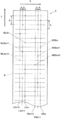
- a recording head used in the ink jet recording apparatus a recording head in which nozzles are arranged in a line on the nozzle surface is often used, but in recent years, as shown in a plan view of FIG.
- a print head having nozzle rows 3m, 3m + 1, and 3m + 2 composed of three rows in which the nozzles N are staggered in the main scanning direction X indicated by the arrow X in the figure at a predetermined interval is often used.
- FIG. 24 there is a recording medium S below the recording head H, that is, in the rear side in the figure, and the surface of the recording head H facing the recording medium S is a nozzle surface P, and each nozzle N is Is formed.
- the arrangement of the nozzles N in which the nozzle positions of the adjacent nozzles N are shifted in the main scanning direction X is referred to as a staggered arrangement.
- the nozzles N3m + 1 and N3m + 2 are also arranged in a row in the sub-scanning direction Y.
- the interval p between the nozzles N3m, N3m + 1, and N3m + 2 is usually 1/3 or 2/3 of the pixel pitch L of the recording medium S. That is, it is formed to be L / 3 or 2L / 3. Further, the interval q in the sub-scanning direction Y between adjacent nozzles N is usually formed to be the same as the pixel pitch L.
- the nozzle row formed with +1 is referred to as nozzle row 3m + 1
- the nozzle row formed with the nozzles N3m + 2 with the nozzle number represented by 3m + 2 is referred to as nozzle row 3m + 2.
- the staggered nozzles N are normally driven in multiple phases.
- each nozzle N3m, N3m + 1 is provided in the recording head H arranged in a staggered manner for each of the three nozzles N as shown in FIG. 24, each nozzle N3m, N3m + 1 is provided.
- N3m + 2 is driven in three phases.
- Conventional three-phase driving of the nozzles N3m, N3m + 1, and N3m + 2 is performed as follows.
- the strobe pulse is switched from STB1 to STB2 and applied to each nozzle N3m + 1 of the nozzle array 3m + 1.
- the drive pulse is applied, ink is ejected to the recording medium S from each nozzle N3m + 1 of the nozzle row 3m + 1 to which the strobe pulse STB2 is applied.
- the nozzle N3m + 1 is located behind the nozzle N3m by L / 3 in the movement direction of the recording head H in the main scanning direction X, the ink ejected from each nozzle N3m + 1 is the recording medium S.
- the ink landed in the sub-scanning direction Y of the ink ejected from each nozzle N3m is landed.
- the strobe pulse is switched from STB2 to STB3 and applied to each nozzle N3m + 2 of the nozzle array 3m + 2.
- a drive pulse is applied in this state, ink is ejected from the nozzles N3m + 2 of the nozzle array 3m + 2 to the recording medium S, and the ink ejected from the nozzles N3m + 2
- the ink ejected from each nozzle N3m + 1 is landed at a position adjacent to the sub-scanning direction Y of the landed ink.
- the strobe pulse is switched in the order of STB 1 ⁇ STB 2 ⁇ STB 3 to switch the drive phase, whereby the ink ejected from each nozzle N 3 m to N 3 m + 2 extends in the sub-scanning direction Y on the recording medium S. Can be landed in a straight line.
- the nozzle N for ejecting ink is switched in order from the nozzle N3m at the forefront in the moving direction of the recording head H in the main scanning direction X to the nozzles N3m + 1 and N3m + 2 on the rear side.
- the method of switching the phase is called the rank phase.
- each nozzle N3m in the nozzle row 3m moves in the main scanning direction X by the pixel pitch L from the position where ink was first ejected. Come in position.
- a strobe pulse is switched from STB3 to STB1 and a drive pulse is applied to each nozzle N3m in the nozzle array 3m
- each nozzle N3m in the nozzle array 3m starts from the position where ink was first ejected.
- Ink is ejected at a position shifted in the main scanning direction X by the pitch L. Therefore, the ink is landed at a position adjacent to the position where the ink is first ejected from each nozzle N3m of the nozzle array 3m and landed on the recording medium S.
- the strobe pulse is switched from STB1 to STB2 and STB3 in order and extends on the recording medium S in the sub-scanning direction Y.
- the ink is landed in a straight line, and the ink is further landed in a straight line at a position adjacent to the main scanning direction X of the ink straight line.
- the ink is landed on each pixel of the recording medium S in such a manner that the operation of landing the ink on the recording medium S in a straight line extending in the sub-scanning direction Y is repeated.
- an image was recorded on the recording medium S.
- the strobe pulse is switched in the order of STB1, STB2, and STB3, and the nozzle N for ejecting ink is set to the recording head.
- the nozzle N3m at the forefront of the movement direction of H is switched in order from the nozzles N3m + 1 and N3m + 2 on the rear side.
- the recording head H when the recording head H performs image recording while moving to the left in the figure, the recording head H Since the nozzle N on the foremost side in the moving direction replaces the nozzle N3m + 2, the nozzle N that ejects ink is switched in order from the nozzle N3m + 2 on the foremost side in the moving direction of the recording head H to the nozzles N3m + 1 and N3m on the rear side.
- the strobe pulse is switched in the order of STB3 ⁇ STB2 ⁇ STB1.
- the moving speed of the recording head H in the main scanning direction X is doubled so that ink is ejected from the same nozzle N every other pixel.
- another recording head H * having a staggered nozzle M is provided in parallel with the recording head H in the main scanning direction X.
- a staggered nozzle M is provided in parallel with the nozzle N in the main scanning direction X on the recording head H provided with the arranged nozzles N.
- the nozzle M is also driven to discharge in the opposite phase.
- the ink is ejected from the nozzle M and landed on the gap portion of the ink ejected from the nozzle N and landed on the recording medium S, and the image is recorded on the recording medium S.
- the strobe pulses STB1 to STB3 when the pulse widths of the strobe pulses STB1 to STB3 (the time interval at which the pulses are at the high level) are shown in FIG. Although it is described as if it has become twice the width, this is because the moving speed of the recording head H has doubled, and the pulse widths of the strobe pulses STB1 to STB3 do not change.
- the ink jet recording apparatus is a line head system, and an image is recorded by ejecting ink to all pixels of the recording medium while the recording medium moves once relative to the recording head. Is the premise. That is, image recording must be performed in a so-called one pass.
- each nozzle of the recording head is driven to discharge in the opposite phase, and the moving speed of the recording head relative to the recording medium is doubled from the conventional moving speed, so that ink is discharged from the nozzle N every other pixel and landed.
- another recording head having a staggered nozzle M is arranged in parallel with the recording head H in the main scanning direction X, or a staggered nozzle is provided. It has become necessary to provide a staggered nozzle M in parallel with the nozzle N in the main scanning direction X on the recording head H provided with N.
- the recording head H having the staggered nozzles N and the recording head having the staggered nozzles M are provided separately, the cost increases by the newly provided recording head. Further, the adjustment operation of the positions of the nozzles N and M of each recording head becomes complicated, and various problems such as the necessity of appropriately adjusting the discharge timing of the nozzles N and M arise. In addition, when both the staggered nozzles N and M are provided in the recording head H, there is a problem that such a dedicated recording head must be newly manufactured.
- the present invention has been made in view of the above problems, and in a serial head type ink jet recording apparatus using a recording head in which nozzles are staggered, a streak pattern is generated in an image on a recording medium.
- An object of the present invention is to provide an ink jet recording apparatus capable of improving the image quality of a recorded image.
- an ink jet recording apparatus is: A recording head having three nozzle rows in which a plurality of nozzles are staggered at L / 3 intervals in the main scanning direction when driven at a driving phase of three phases and a pixel pitch is L; Each nozzle row of the recording head is driven to discharge in order from the last nozzle row in the relative movement direction of the recording head to the recording medium to the front nozzle row, and the discharge frequency for each nozzle row of the recording head is set to f.
- the recording head includes two sets of nozzle rows each including the three rows, and the two nozzle rows are arranged in parallel in the main scanning direction.
- the interval in the sub-scanning direction between adjacent nozzles in the same nozzle row set is set to be twice the pixel pitch, and the nozzles in one set of nozzle rows are in the other set. It is characterized in that it is provided by being shifted by one pixel pitch in the sub-scanning direction with respect to the nozzles in the nozzle row.
- the recording head includes two sets of nozzle rows each including the three rows, and the two sets of nozzle rows are arranged in parallel in the main scanning direction.
- the interval in the sub-scanning direction between adjacent nozzles in the same nozzle row set is set to 4 times the pixel pitch, and the nozzles in one set of nozzle rows are in the other set. It is characterized by being provided with a shift of two pixel pitches in the sub-scanning direction with respect to the nozzles of the nozzle row.
- the control unit is configured to perform a single scan in the main scanning direction of the recording head. With respect to the ink ejection operation from each nozzle for each ejection cycle to be performed, a discharge cycle for ejecting ink from each nozzle and a ejection cycle for not ejecting ink from each nozzle are provided.
- the ink that has not been ejected from the nozzle should naturally land. Since the ink ejected from another normal nozzle is landed and filled in the pixel position adjacent to the pixel position, the portion where the ink is not ejected in the image recorded on the recording medium continues in the main scanning direction. Arrangement is prevented, and a phenomenon in which a streak-like pattern appears in the image is avoided. For this reason, it is possible to suppress deterioration in image quality and improve image quality.
- an image can be recorded on the recording medium by one scanning of the recording head (so-called one pass).
- the recording method of the present invention an image is recorded on the recording medium.
- the recording head needs to be scanned twice (so-called two passes), since the moving speed of the recording head in the main scanning direction is twice the conventional moving speed, the time required for image recording is the conventional recording method. It is not much different from the case of. That is, according to the first aspect of the present invention, it is possible to avoid the phenomenon of streak-like patterns in an image, which could not be avoided by the conventional recording technique, in the same recording time as that of the conventional recording technique. Is possible.
- the recording head includes two sets of three nozzle rows, and the two nozzle rows are arranged in parallel in the main scanning direction, and are adjacent to each other in the same nozzle row set.
- the interval between the nozzles in the sub-scanning direction is set to twice the pixel pitch, and the nozzles in one set of nozzle rows are one pixel pitch in the sub-scanning direction with respect to the nozzles in the other set of nozzle rows.
- the recording head includes two sets of three nozzle rows, and the two nozzle rows are arranged in parallel in the main scanning direction and are adjacent to each other in the same nozzle row set.
- the interval between the nozzles in the sub-scanning direction is set to four times the pixel pitch, and the nozzles in one set of nozzle rows are two pixel pitches in the sub-scanning direction with respect to the nozzles in the other set of nozzle rows.
- the ink is discharged from the nozzle N.
- Multiple pixel positions in the area between non-ejected pixel positions are filled with multiple inks ejected from different normal nozzles, so that pixel positions where no ink is ejected diffusely in the image
- FIG. 1 is a schematic perspective view illustrating an overall configuration of an ink jet recording apparatus.
- FIG. 4 is an enlarged view of a carriage portion including a recording head.
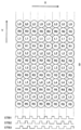
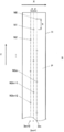
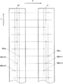
- FIG. 3 is a plan view illustrating a configuration of a recording head.
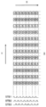
- FIG. 6 is a diagram illustrating pixel positions and strobe pulses where ink is landed when ink is ejected by a conventional recording method in the first embodiment.
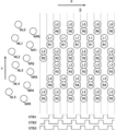
- It is a schematic perspective view which shows the structure containing the head drive circuit of a carriage upper part.
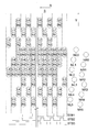
- It is a figure which shows the structure of a head drive circuit.
- It is a figure which shows the example of the drive waveform of a nozzle drive signal.
- It is a block diagram which shows the control structure of an inkjet recording device.
- FIG. 1 is a schematic perspective view illustrating an overall configuration of an ink jet recording apparatus.
- FIG. 4 is an enlarged view of a carriage portion including a recording head.
- FIG. 3 is a plan view
- FIG. 4 is a diagram illustrating pixel positions and the like where ink is landed when ink is ejected from an ink column on the right side of the recording head by the recording method of the present invention in the first embodiment.
- FIG. 3 is a diagram illustrating pixel positions and the like where ink is landed when ink is ejected from the left and right ink columns of the recording head by the recording method of the present invention in the first embodiment.
- FIG. 11 is a diagram illustrating a pixel position in FIG. 10 and a pixel position where ink is landed by scanning in the opposite direction of the recording head. It is a figure which shows the pixel position in the image in which ink is not discharged from a nozzle in 1st Embodiment.
- FIG. 10 is a diagram illustrating pixel positions and strobe pulses where ink is landed when ink is ejected by a conventional recording method in the second embodiment.
- FIG. 10 is a diagram illustrating a pixel position where ink is landed when ink is ejected from an ink column on the right side of a recording head by the recording method of the present invention in a second embodiment.
- FIG. 10 is a diagram illustrating pixel positions and the like where ink is landed when ink is ejected from the left and right ink columns of the recording head by the recording method of the present invention in the second embodiment.
- FIG. 19 is a diagram illustrating a pixel position in FIG. 18 and a pixel position where ink is landed by scanning in the opposite direction of the recording head.
- FIG. 10 is a diagram illustrating pixel positions and the like where ink is landed when ink is ejected from an ink column on the right side of a recording head by the recording method of the present invention in a third embodiment.
- FIG. 10 is a diagram illustrating pixel positions and the like where ink is landed when ink is ejected from the left and right ink columns of a recording head by the recording method of the present invention in a third embodiment.
- FIG. 22 is a diagram illustrating a pixel position in FIG. 21 and a pixel position where ink is landed by scanning in the opposite direction of the recording head. It is a figure which shows the pixel position in the image in which an ink is not discharged from a nozzle in 3rd Embodiment.
- FIG. 10 is a diagram illustrating pixel positions and the like where ink is landed when ink is ejected from an ink column on the right side of a recording head by the recording method of the present invention in a third embodiment.
- FIG. 3 is a plan view showing a configuration of a general recording head having nozzle rows composed of three rows arranged in a staggered manner.
- FIG. 25 is a diagram illustrating pixel positions and strobe pulses where ink is landed when ink is ejected by the conventional recording method using the recording head of FIG. 24.
- FIG. 26 is a diagram illustrating pixel positions in an image where ink is not ejected from nozzles when ink is ejected by the conventional recording method of FIG. 25.
- FIG. 25 is a diagram illustrating pixel positions where ink is landed when ink is ejected from the recording head of FIG. 24 by the recording method described in Patent Document 2.
- FIG. 25 is a diagram illustrating pixel positions where ink is landed when ink is ejected from the recording head of FIG. 24 by the recording method described in Patent Document 2.
- FIG. 3 is a plan view showing a configuration in which two recording heads are arranged in parallel in the main scanning direction.
- FIG. 3 is a plan view showing a configuration in which a staggered nozzle array is arranged in parallel in the main scanning direction on one recording head.
- FIG. 30 is a diagram illustrating pixel positions where ink is landed when ink is ejected using the recording head of FIG. 28 or FIG. 29.
- the ink jet recording apparatus 1 As shown in FIG. 1, the ink jet recording apparatus 1 according to the first embodiment mainly includes a transport unit 2, a main scanning unit 3, and a computer 4.
- FIG. 2 is an enlarged view of a carriage 32 portion including a recording head 5 described later in the internal structure of the main scanning unit 3.
- a driving roller 21 extending in the main scanning direction X and a driven roller are rotatably supported on the upper portion of the transport unit 2, and the driving roller 21 is rotationally driven on one end side of the driving roller 21.
- a drive motor 22 is attached.
- An endless conveying belt 23 is stretched between the driving roller 21 and the driven roller. The conveying belt 23 circulates between the driving roller 21 and the driven roller when the driving roller 21 rotates.
- the drive motor 22 rotates the drive roller 21 by a predetermined amount to move the recording medium S in the transport direction when the recording head 5 finishes one scan in the main scanning direction X according to the control of the control means 9 described later.
- the driving roller 21 is rotated again by a predetermined amount to convey the recording medium S in the conveying direction Z.
- the recording medium S is repeatedly conveyed by a predetermined distance and stopped so that the recording medium S is intermittently conveyed.
- the conveyance direction Z of the recording medium S is set to be parallel to the sub-scanning direction Y orthogonal to the main scanning direction X. Further, it is not necessary to configure the recording medium S to be transported by the transport belt 23.
- the recording medium S may be configured to move on a flat platen in the transport direction Z (sub-scanning direction Y). Is possible.
- the recording medium S can be made of resin film, metal, or the like in addition to paper and fabric, and is not particularly limited.
- the main scanning unit 3 is disposed above the conveyance belt 23 of the conveyance unit 2. Inside the main scanning unit 3, a rod-shaped carriage rail 31 is disposed so as to extend in the main scanning direction X. On the carriage rail 31, a substantially casing-shaped carriage 32 is arranged in the main scanning direction X. It is supported so that it can reciprocate. The carriage 32 is moved and scanned in the main scanning direction X along the carriage rail 31 by driving of a scanning drive mechanism including a motor (not shown).
- a surface P (hereinafter referred to as a plurality of nozzles N) that discharges ink of each color such as yellow (Y), magenta (M), cyan (C), black (K) and the like when recording an image.
- a plurality of recording heads 5 arranged on the nozzle surface P) are mounted, and ink droplets of each color are ejected from the nozzles N of the recording heads 5 to the recording medium S on the transport belt 23. It is like that.
- the carriage 32 accommodated piping (not shown) for supplying ink from an ink tank 81 to be described later to the recording head 5, wiring (not shown) for transmitting an electric signal and power for driving the recording head 5 and the like.
- a cable bear 33 is connected.
- one end side of the main scanning unit 3 in the main scanning direction X is a maintenance unit 6 for performing maintenance of the recording head 5, and the main scanning unit 3, the nozzles of the recording head 5 during the non-recording operation are arranged so that the nozzles N of the recording head 5 are dried during the non-recording operation and ink discharge from the nozzles N is not defective.
- the nozzle moisturizing unit 7 is used to cap and moisturize the surface P.
- an ink rack 8 including an ink tank 81 for storing each color ink to be supplied to each recording head 5 is disposed behind the main scanning unit 3. Ink is supplied from each ink tank 81 to each recording head 5 via the above-described piping, an ink supply pipe (not shown), or the like.
- the main scanning unit 3 image processing for converting image data of an image to be recorded on a recording medium S input from an external device (not shown) into data corresponding to each nozzle N of the recording head 5.
- the computer 4 is arranged, and data and the like are serially transferred from the computer 4 to a head driving circuit (not shown) that drives the recording head 5 through the wiring described above.
- the computer 4 is configured by a general-purpose computer in which a CPU (Central Processing Unit), a ROM (Read Only Memory), a RAM (Random Access Memory), an input / output interface, and the like (not shown) are connected to a bus. ing.
- a plurality of nozzles N3m, N3m + 1, N3m + 2 as shown in FIG. 24 are arranged in a staggered arrangement in the main scanning direction X at L / 3 intervals.
- an existing recording head as shown in FIG. 3 is used as the recording head 5.
- the recording head 5 is driven for each driving phase composed of three phases, and a plurality of nozzles N are arranged in three rows staggered in the main scanning direction X at L / 3 intervals (L is a pixel pitch). Two sets of nozzle rows are arranged in parallel in the main scanning direction X of the recording head 5.
- the right set of nozzle rows in the figure is represented as R3m, R3m + 1, R3m + 2, and the nozzles belonging to the nozzle rows R3m, R3m + 1, R3m + 2 are represented as nozzles NR3m, NR3m + 1, and NR3m + 2, respectively.
- the left nozzle set is represented as L3m, L3m + 1, L3m + 2, and the nozzles belonging to the nozzle rows L3m, L3m + 1, L3m + 2 are represented as nozzles NL3m, NL3m + 1, and NL3m + 2, respectively.
- a total of 512 nozzles N are formed, with an even number of 256 nozzles for each of the left and right groups.
- the recording head 5 is used to record an image on the recording medium S at a resolution of 360 dpi.
- the pixel pitch L is 70.5 ⁇ m, so that the three nozzle arrays on the left and right are connected to each other.
- the interval p is set to 23.5 ⁇ m, which is 1/3 of the interval p.
- the interval between the corresponding nozzle rows on the left and right that is, the interval between the nozzle row R3m and the nozzle row L3m, the nozzle row R3m + 1 and the nozzle row L3m + 1, and the nozzle row R3m + 2 and the nozzle row L3m + 2 is 1. .44 mm.
- the ejection frequency (that is, the ejection frequency for each nozzle N) f of each nozzle row of the recording head 5 of the present embodiment is set as appropriate, for example, about 6.7 kHz.
- the interval q in the sub-scanning direction Y between adjacent nozzles N in the same nozzle row set is set to twice the pixel pitch L, that is, 141 ⁇ m.
- the nozzles N are provided by being shifted by one pixel pitch L in the sub-scanning direction Y.
- the recording head 5 is moved and scanned in the main scanning direction X at a moving speed of L ⁇ f, and the nozzles NR3m, NR3m + 1, NR3m + 2 and the nozzles NL3m, NL3m + of the recording head 5 of this embodiment. 1 and NL3m + 2 are each driven to discharge in order as shown in FIG. 25 (that is, each nozzle row of the recording head 5 is moved relative to the recording medium S in the relative movement direction of the recording head 5 (main scanning direction X ) In the main scanning direction X of the recording head 5, as shown in FIG.
- the ink ejected from the nozzles NR3m to NR3m + 2 and the nozzles NL3m to NL3m + 2 does not land on the same position on the recording medium S, but landers at different positions.
- the recording head 5 of the present embodiment structurally appears to be similar to the recording head H used in the ink jet recording apparatus described in Patent Document 2 shown in FIG. 29, but its function is Unlike the recording head H shown in FIG. 29, a plurality of nozzle rows N3m, N3m + 1, N3m + 2 shown in FIG. 24 are arranged in a staggered arrangement in the main scanning direction X at L / 3 intervals. It functions in the same manner as the recording head H having 3m, 3m + 1, and 3m + 2.
- the recording head 5 of the present embodiment can perform scanning once (that is, in one pass) when the ejection driving is performed by the conventional three-phase driving as described above. ) It is possible to record an image on the recording medium S by landing ink on each pixel of the recording medium S.
- the cable bear 33 is connected to the upper portion of the carriage 32 shown in FIG. 2 as described above.
- the ink supply pipe 36 is connected via a joint 35.
- the ink supply pipes 36 are connected to the recording heads 5 (not shown in FIG. 5), and the inks of the respective colors supplied from the ink tank 81 (see FIG. 1) are respectively connected to the pipes 34 and the ink supply pipes 36. Is supplied to each recording head 5 via the.
- each piping 34 is accommodated in a resin tube 37 for each predetermined number, and the piping 34 and the wiring 38 are partitioned in the cable bear 33 so that they do not rub against each other.
- a partition wall 39 is provided.
- the wiring 38 is connected to the head drive circuit 51 via the connector 40 or the like, and transmits data or the like serially transferred from the computer 4 to the head drive circuit 51.
- the head drive circuit 51 includes a shift register 52, a latch circuit 53, a level shifter circuit 56, a drive waveform generator 57, and the like.
- the head drive circuit 51 temporarily shifts the data d1, d2,. The data are sequentially stored in the register 52.
- the latch circuit 53 When the data d1, d2,..., Dn are accumulated in the shift register 52, when the latch signal LAT is input to the latch circuit 53, the latch circuit 53 receives the data d1 from the shift register 52 at that timing. , D2,..., Dn, and processing such as changing the order of each data as necessary is appropriately performed. Further, the next series of data is sequentially stored in the empty shift register 52.
- the data d1, d2,..., Dn output from the latch circuit 53 are transmitted to the comparator 54, sequentially output from the comparator 54 in accordance with the strobe clock STBCLK, and data d1, d2 output from the comparator 54. ,..., Dn are sent to the AND circuits 55, respectively.
- the AND circuit 55 when either the data d output from the comparison unit 54 or the strobe pulses STB1, STB2, STB3 is ON, the data d is input from the AND circuit 55 to which the ON strobe pulse STB is input to the level shifter circuit 56. Is sent.
- the strobe pulse STB2 when the strobe pulse STB1 is at a high level, the strobe pulse STB2 is high from the nozzles NR3m and NL3m (see FIG. 3). Ink is ejected from the nozzles NR3m + 1 and NL3m + 1 when the level is high, and from the nozzles NR3m + 2 and NL3m + 2 when the strobe pulse STB3 is at the high level. Yes.
- the strobe pulses STB1, STB2, and STB3 are switched in the order phase or the opposite phase, so that the nozzles NR3m, NR3m + 1, NR3m + 2 and the nozzles NL3m, NL3m + 1, NL3m + of the recording head 5 are switched. 2 is driven three-phase in the order phase or opposite phase.
- the level shifter circuit 56 sends the data d1, d2,..., Dn to the drive waveform generator 57 in accordance with the upper and lower voltages, and the drive waveform generator 57 uses the data d1, d2,. For example, nozzle drive signals D1, D2,..., Dn having drive waveforms as shown in FIG. 7 are generated, and the nozzle drive signals D1, D2,. , Dn are sequentially transmitted.
- each nozzle N of the recording head 5 is driven in three phases, and when the nozzle drive signal D is applied in a state where the high level strobe pulse STB is applied, the nozzle N is illustrated.
- the piezo elements that are not deformed are deformed according to the drive waveform of the nozzle drive signal D, and ink is ejected from the nozzles N, respectively.
- FIG. 8 is a block diagram showing a control configuration of the ink jet recording apparatus according to the present embodiment.
- the ink jet recording apparatus 1 includes a control unit 9.
- the control means 9 can be configured in the computer 4 described above, but can also be configured by a general-purpose computer separate from the computer 4 or a microcomputer having a dedicated processor.
- the control unit 9 controls the operation of each functional unit of the apparatus.
- the control unit 9 drives the scanning drive mechanism 10 to move the carriage 32 (see FIGS. 1 and 2) along the carriage rail 31 in the main scanning direction.
- the driving motor 22 is driven in accordance with the scanning in the main scanning direction X of each recording head 5 that is scanned above the recording medium S as the carriage 32 moves, and the conveying belt is moved.
- the recording medium S is intermittently transported by intermittently moving 23 in the transport direction Z (sub-scanning direction Y).
- control unit 9 appropriately drives a pump 11 provided in the ink supply system so as to supply ink from the ink tank 81 to each recording head 5 via the pipe 34 and the ink supply pipe 36.
- control means 9 is provided with input means (not shown) such as a mouse, a keyboard, and a touch panel, so that the ejection frequency f for each nozzle row of the recording head 5 can be set. Yes.
- control means 9 controls the computer 4 so that each head N corresponding to each nozzle N of each recording head 5 which the head driving circuit 51 is in charge of, as shown in FIG. Data d1, d2,... Are serially transferred at a predetermined timing.
- the control means 9 scans the recording head 5 in the main scanning direction X at a moving speed of L ⁇ f as in the conventional recording method, and the nozzle rows R3m, R3m + 1, R3m + 2 of the recording head 5 and The driving phase of each nozzle N in the nozzle rows L3m, L3m + 1, and L3m + 2 is switched according to the rank phase, or the moving speed of the recording head 5 is doubled, that is, 2 ⁇ L ⁇ f in the main scanning direction X To which the nozzles R3m, R3m + 1, R3m + 2 and the nozzles N of the nozzle rows L3m, L3m + 1, L3m + 2 are switched in the opposite phase. It can be specified via.
- the control unit 9 sets the moving speed in the main scanning direction X of the carriage 32 on which the recording head 5 is mounted to the scanning drive mechanism 10 to L ⁇ f. Further, with respect to the head drive circuit 51, the nozzle rows R3m to R3m + 2 and the nozzle rows L3m to L3m + 2 of the recording head 5 are moved forward with respect to the recording medium S relative to the recording medium 5 (main scanning direction X). The nozzles are set so as to be driven in order from the nozzle row to the rear nozzle row (that is, so as to drive in the order phase).
- the recording head 5 shown in FIG.
- the strobe pulse STB applied to each nozzle N is switched in the order of STB1, STB2, and STB3, and the recording head 5 scans in the direction opposite to the main scanning direction X.
- the strobe pulse STB applied to each nozzle N is switched in the order of STB3 ⁇ STB2 ⁇ STB1.
- the recording head 5 moves and scans in the main scanning direction X at a moving speed of L ⁇ f, and the nozzle rows R3m to R3m + 2 of the recording head 5 and As shown in FIG. 4, ink is ejected from the nozzles NR3m to NR3m + 2 and NL3m to NL3m + 2 of the nozzle array L3m to L3m + 2 at the pixel positions of the recording medium S corresponding to the nozzles N, respectively. Ink is successively ejected to pixels adjacent in the main scanning direction X, and an image is recorded on the recording medium S.
- the control means 9 sets the moving speed in the main scanning direction X of the carriage 32 on which the recording head 5 is mounted to the scanning drive mechanism 10 by 2 ⁇ .
- L ⁇ f, and the nozzle array R3m to R3m + 2 and the nozzle array L3m to L3m + 2 of the recording head 5 with respect to the head drive circuit 51 are moved relative to the recording medium S in the direction of relative movement of the recording head 5 ( It is set so that ejection driving is performed in order from the last nozzle row in the main scanning direction X) to the front nozzle row (that is, ejection driving is performed in reverse phase).
- the nozzle rows R3m to R3m + 2 and the nozzle rows L3m to L3m + 2 of the recording head 5 are driven to discharge in opposite phases
- the recording head 5 shown in FIG. 3 is scanned once in the main scanning direction X
- the strobe pulse STB applied to each nozzle N is switched in the order of STB3 ⁇ STB2 ⁇ STB1
- the recording head 5 is scanned in a direction opposite to the main scanning direction X, for example,
- the strobe pulse STB applied to each nozzle N is switched in the order of STB1, STB2, and STB3.
- the nozzles NR3m, NR3m + 1, and NR3m + 2 of the nozzle rows R3m, R3m + 1, and R3m + 2 of the recording head 5 are respectively shown in FIG.
- Ink is ejected to the corresponding pixel positions of the recording medium S every other pixel in the main scanning direction X.
- each nozzle NR3m, NR3m + 1, NR3m + 2 has the interval q between the adjacent nozzles N in the sub-scanning direction Y set to twice the pixel pitch L, the sub-scanning direction Y
- ink is ejected every other pixel.
- ink is ejected from the nozzles NL3m, NL3m + 1, and NL3m + 2 of the nozzle rows L3m, L3m + 1, and L3m + 2 of the recording head 5, but the nozzles NL3m, NL3m + 1, and NL3m + 2 are also ejected.
- nozzles NL3m, NL3m + 1, and NL3m + 2 are also ejected.
- ink is ejected to pixel positions adjacent to the sub-scanning direction Y of the pixel positions from which ink was ejected from the nozzles NR3m, NR3m + 1, and NR3m + 2.
- the recording head 5 is moved in the main scanning direction X without transporting the recording medium S in the transport direction Z (sub-scanning direction Y).
- the ink ejected from each nozzle N is the same position in the sub-scanning direction on the recording medium S as in the case shown in FIG. Discharged.
- the nozzle N extends in the main scanning direction X at a position corresponding to the nozzle N in the image recorded on the recording medium S. It will be in the state where the line-like pattern entered.
- the control means 9 drives the drive motor 22 to move the recording medium S in the transport direction Z (sub-scanning direction Y).
- the ink is landed on the recording medium S by the previous scanning of the recording head 5 in the next scanning of the recording head 5 in the opposite direction of the main scanning direction X.
- Ink is ejected from each nozzle to a pixel position other than the pixel position.
- the control unit 9 moves the recording medium S in the sub-scanning direction.
- Y for example, upward direction in the figure
- the pixel pitch is moved by, for example, a distance of 6 times, and stopped, and in the next scan in the direction opposite to the main scanning direction X of the recording head 5, as shown in FIG.
- Ink is ejected from each nozzle to a pixel position adjacent to the pixel position where ink has landed on the recording medium S in the previous scan of the head 5. Note that how many pixel pitches the recording medium S is moved in the sub-scanning direction Y is appropriately set.
- W1 is the interval in the sub-scanning direction Y between adjacent nozzles N in the recording head, and specifically, for example, the interval between NL0 and NR0.
- W1 number of nozzles ⁇ W2 / W3, where W3 is the number of multipasses.
- W2 is 1 times the pixel pitch
- the number of nozzles is 12, and the number of multipasses W3 is 2, as will be described later. Therefore, the movement distance W1 is equal to the pixel pitch. 6 times.
- the ink ejected from the same nozzle N of the recording head 5 does not land at least on adjacent pixel positions on the recording medium S. For this reason, even when there is a nozzle N that does not normally eject ink due to a lack of nozzle in a part of the nozzle N, as shown in FIG. Since the ink ejected from another normal nozzle N is landed and filled in the pixel position adjacent to the pixel position, the portion where the ink is not ejected in the image recorded on the recording medium S is in the main scanning direction X. It is prevented that the images are continuously arranged, and a phenomenon in which a streak-like pattern appears in the image is avoided, so that deterioration in image quality can be suppressed.
- the recording head 5 is scanned in the main scanning direction X at a moving speed of 2 ⁇ L ⁇ f, and the nozzle arrays R3m to R3m + 2 and the nozzle arrays L3m to L3m + of the recording head 5 are scanned.
- the nozzles 2 are ejected in the opposite phase, the pixel positions of the ink ejected from the nozzles N of the recording head 5 and landed on the recording medium S are scattered pixel positions as shown in FIGS. 10 and 11, for example. become. Therefore, it is necessary to appropriately rearrange the data arrangement order when serially transferring each data corresponding to each nozzle N of the recording head 5 from the computer 4 to the head driving circuit 51.
- the image recorded on the recording medium S is a pixel row represented by inks L3, L0, L3, L0, L3, L0,... Extending in the main scanning direction X.
- Each pixel position of an image recorded on the recording medium S is represented by coordinates (x, y).
- data corresponding to a nozzle N that ejects ink at a pixel position represented by coordinates (x, y) is represented by d (x, y).
- the computer 4 stores, in the RAM, each data d (x, y) obtained by converting image data of an image to be recorded on the recording medium S input from an external device (not shown) into a form corresponding to each nozzle N of the recording head 5. expand.
- each data d (x, y) obtained by converting image data of an image to be recorded on the recording medium S input from an external device (not shown) into a form corresponding to each nozzle N of the recording head 5. expand.
- the computer 4 applies 0, 0, 0, respectively to the nozzles NR0, NR1, NR2, NR3, NR4, NR5,.
- Each data of d (0, 1), 0, 0,.
- the computer 4 sequentially associates each data of 0, 0, 0, d (0, 0), 0, 0,... With the nozzles NL0, NL1, NL2, NL3, NL4, NL5,. Arrange. Each data is concatenated and arranged in the form of 0, 0, 0, d (0, 1), 0, 0,..., 0, 0, 0, d (0, 0), 0, 0,. . Note that data having a value of 0 is so-called dummy data and represents that ink is not ejected.
- the ink ejected from the nozzles NR0, NR1,..., NL0, NL1,... In the next ejection cycle lands on the pixel positions of R0, R1,..., L0, L1,. 4 represents nozzles NR0, NR1, NR2, NR3, NR4, NR5,..., 0, 0, 0, d (2, 1), d (1, 3), d (0, 5),.
- ... Are sequentially associated and connected.
- the computer 4 stores data d (x, y) corresponding to each pixel position of the recording medium S on which ink ejected from the nozzles NR0, NR1,..., NL0, NL1,. ), Or when there is no data at the corresponding pixel position, each data is arranged in association with dummy data 0, a data string in an appropriate arrangement order is created, and serially transferred to the head drive circuit 51.
- the creation of the data string may be performed in advance before the recording operation is started, or may be configured to be performed in parallel with the recording operation.
- control means 9 and the processing in the computer 4 as described above are not processing specific to the recording head 5 shown in FIG. 3, but a general recording head as shown in FIG. The same can be done when H is used.
- the recording heads 5 and H are provided in the serial head type ink jet recording apparatus using the recording head 5 and the recording head H in which the nozzles N are staggered.
- the nozzles of the recording head 5 and H are moved by scanning at a moving speed (2 ⁇ L ⁇ f) that is twice the conventional moving speed (L ⁇ f).
- the ejection drive is performed sequentially from the last nozzle row in the relative movement direction (main scanning direction X) to the front nozzle row. That is, ejection driving is performed in the opposite phase.
- the recording medium S is moved by a predetermined distance of the pixel pitch L in the sub-scanning direction Y with respect to the recording heads 5 and H. Then, the next scanning is performed, and the ink is ejected from each nozzle N to a pixel position other than the pixel position where the ink has landed on the recording medium S in the previous scanning of the recording heads 5 and H.
- the inkjet recording apparatus described in Patent Document 2 is used.
- an image can be recorded on the recording medium S by one scan (so-called one pass) of the recording heads 5 and H, but the book shown in FIG.
- two scans in order to record an image on the recording medium S, two scans (so-called two passes) of the recording heads 5 and H are required.
- the moving speed of the recording heads 5 and H in the main scanning direction X is twice the conventional moving speed, the time required for image recording is not much different from that in the conventional recording method. That is, according to the present invention, it is possible to avoid the streak-like pattern mixing phenomenon in the image, which could not be avoided by the conventional recording method, in the same recording time as that of the conventional recording method.
- the interval between the corresponding nozzle rows on the left and right that is, the interval between the nozzle row R3m and the nozzle row L3m is set to 1.44 mm.
- this interval corresponds to about 20.4 pixels.
- the discharge timings of the nozzle rows R3m to R3m + 2 and the nozzle rows L3m to L3m + 2 are set.
- ink is ejected from each nozzle N at independent ejection timings without synchronizing the ejection timings of the nozzle rows R3m to R3m + 2 and the nozzle rows L3m to L3m + 2. It can be configured as follows.
- the nozzle rows R3m to R3m + 2 and the nozzle rows L3m to L3m + 2 may not be configured to be driven to discharge at independent discharge timings.
- the ink discharged from each nozzle N of the nozzle rows R3m to R3m + 2 is adjusted by adjusting the discharge frequency (that is, the discharge frequency for each nozzle N) f for each nozzle row of the recording head 5.
- the landing positions on the recording medium S of the ink ejected from the nozzles N of the nozzle rows L3m to L3m + 2 can be aligned in the sub-scanning direction Y.
- the moving speed (2 ⁇ L ⁇ f) of the recording head 5 also changes in accordance with the change in the ejection frequency f.
- the recording head 5 (see FIG. 3) is driven for each driving phase consisting of three phases, and a plurality of nozzles N are staggered in the main scanning direction X at L / 3 intervals (L is a pixel pitch).
- L is a pixel pitch
- two nozzle groups each having three columns are arranged in parallel in the main scanning direction X of the recording head 5 in the same manner as in the first embodiment, and the nozzle N is 256 for each of the left and right groups.
- the recording head 5 is used to record an image on the recording medium S with a resolution of 720 dpi, that is, a resolution twice that of the first embodiment. It is like that.
- the pixel pitch L is 35.3 ⁇ m
- the interval p between the three right and left nozzle columns is set to 1/3 of 1/3 ⁇ m.
- the interval between the corresponding nozzle rows on the left and right that is, the interval between the nozzle row R3m and the nozzle row L3m is 1.44 mm
- the ejection frequency for each nozzle row (that is, the ejection frequency for each nozzle N) f is
- the point set to about 6.7 kHz is the same as that of the first embodiment.
- the interval q in the sub-scanning direction Y between adjacent nozzles N in the same nozzle row set is set to four times the pixel pitch L, and the left and right nozzle rows In the set, the nozzles N are provided with a shift of 2 pixel pitches L in the sub-scanning direction Y. This is also different from the first embodiment.
- the recording head 5 is moved and scanned in the main scanning direction X at a moving speed of L ⁇ f, and the nozzles NR3m, NR3m + 1, NR3m + 2 and the nozzles NL3m, NL3m + of the recording head 5 of this embodiment. 1 and NL3m + 2 are ejected in the order phase as shown in FIG. 25, and then ejected in the conventional three-phase drive as shown in FIG. 25, the main scanning direction of the recording head 5 as shown in FIG.
- Ink discharged from the nozzles N of the nozzles NR3m to NR3m + 2 and the nozzles NL3m to NL3m + 2 in one scan to X is landed every other pixel in the sub-scanning direction Y.
- the recording head 5 when the recording head 5 is driven to discharge by the conventional three-phase driving as described above, the recording head 5 is scanned twice (that is, in two passes). ) Ink is landed on each pixel of the recording medium S to record an image on the recording medium S.
- the control means 9 determines the moving speed in the main scanning direction X of the carriage 32 on which the recording head 5 is mounted with respect to the scanning drive mechanism 10.
- 2 ⁇ L ⁇ f is set, and the nozzle array R3m to R3m + 2 and the nozzle array L3m to L3m + 2 of the recording head 5 are moved relative to the recording medium S with respect to the head driving circuit 51. It is set so that ejection driving is performed in order from the last nozzle row in the direction (main scanning direction X) to the front nozzle row (that is, ejection driving is performed in reverse phase).
- the recording head 5 moves at a moving speed of 2 ⁇ L ⁇ f in the main scanning direction X.
- the nozzles NR3m, NR3m + 1, NR3m + 2 of the nozzle rows R3m, R3m + 1, R3m + 2 of the recording head 5 respectively scan the corresponding recording medium S as shown in FIG. Ink is ejected at every other pixel position in the main scanning direction X.
- each nozzle NR3m, NR3m + 1, and NR3m + 2 has an interval q in the sub-scanning direction Y between adjacent nozzles N set to four times the pixel pitch L.
- ink is ejected every three pixels.
- ink is ejected from the nozzles NL3m, NL3m + 1, and NL3m + 2 of the nozzle rows L3m, L3m + 1, and L3m + 2 of the recording head 5, but the nozzles NL3m, NL3m + 1, and NL3m + 2 are also ejected.
- nozzles NL3m, NL3m + 1, and NL3m + 2 are also ejected.
- control unit 9 drives the drive motor 22 to move the recording medium S in the transport direction Z (sub-scanning direction Y) when the scanning of the recording head 5 in the main scanning direction X is completed. ) Is moved by a predetermined distance of the pixel pitch and stopped, and in the next scan in the direction opposite to the main scanning direction X of the recording head 5, the ink on the recording medium S is scanned by the previous scanning of the recording head 5. Ink is ejected from each nozzle to a pixel position other than the landed pixel position.
- the control unit 9 moves the recording medium S in the sub-scanning direction.
- Y for example, the upward direction in the figure
- the pixel pitch is moved by a distance of, for example, 13 times and stopped, and in the next scan in the direction opposite to the main scanning direction X of the recording head 5, as shown in FIG.
- Ink is ejected from each nozzle to the pixel position at the lower right in the figure of the pixel position where the ink has landed on the recording medium S in the previous scan of the head 5.
- W2 is twice the pixel pitch
- W2 is greater than or equal to twice the pixel pitch
- the ink is ejected from each nozzle to the lower right pixel position in the drawing of the pixel position where the ink has landed on the recording medium S in the previous scan. Is 13 times the pixel pitch.
- the control unit 9 again moves the recording medium S by a distance of 11 times the pixel pitch in the sub-scanning direction Y (for example, the upward direction in the figure).
- the third scan of the recording head 5 is performed by moving and stopping, and in the third scanning of the recording head 5, the pixel position on the right side of the figure where the ink is landed on the recording medium S in the first scan is shown. Ink is ejected from each nozzle to the pixel position.
- the control unit 9 When the third scan of the recording head 5 is completed, the control unit 9 further moves the recording medium S in the sub-scanning direction Y (for example, upward in the figure) by a distance 13 times the pixel pitch and stops it.
- the fourth scan of the recording head 5 is performed, and in the fourth scanning of the recording head 5, each pixel position at the lower side in the figure of the pixel position where the ink is landed on the recording medium S in the first scan is displayed. Ink is ejected from the nozzles.
- the ink ejected from the same nozzle N of the recording head 5 reaches at least the adjacent pixel position on the recording medium S.
- the nozzle N discharges from the nozzle N. Ink ejected from another normal nozzle N is landed and filled in a pixel position adjacent to the pixel position where the ink that should not have landed should be landed.
- the ink ejected from one nozzle N is landed on the recording medium S at intervals rather than every other pixel in the main scanning direction X, and the pixel position of the gap is set to other nozzles. If it is configured to be filled with ink ejected from N, it is possible to make the pixel positions where ink is not ejected from the abnormal nozzle N more diffused in the image, and in the image recorded on the recording medium S. It is possible to more accurately avoid the formation of a streak-like pattern on the surface.
- the control unit 9 causes the ink from the nozzles N to be ejected for each ejection cycle to be performed during one scan of the recording head 5 in the main scanning direction X.
- a discharge cycle for discharging ink from each nozzle N and a discharge cycle for not discharging ink from each nozzle N are provided.
- the recording head 5 (see FIG. 3) used in the inkjet recording apparatus 1 according to the first embodiment is used as the recording head 5 will be described.
- the recording head 5 used in the second embodiment is described. The same applies to the case of using.
- the recording method of the present invention is adopted as in the case of the first and second embodiments. That is, the control means 9 moves the recording head 5 in the main scanning direction X at a moving speed of 2 ⁇ L ⁇ f, and scans the nozzles R3m to R3m + 2 and nozzle rows L3m to L3m + of the recording head 5. 2 is driven to discharge in the opposite phase.
- the recording medium S is moved in the transport direction Z (sub-scanning direction Y) by a distance that is a predetermined multiple of the pixel pitch. This is the same as in the case of the second embodiment.
- control means 9 uses the nozzles for the ink ejection operation from the nozzles N for each ejection cycle to be performed during one scan of the recording head 5 in the main scanning direction X.
- the ejection cycle in which ink is ejected from N and the ejection cycle in which ink is not ejected from each nozzle N can be set to be repeated every one ejection cycle.
- whether or not to provide an ejection cycle that does not eject ink is set according to a user's setting input. Further, how to set the ejection cycle for ejecting ink from each nozzle N and the ejection cycle for not ejecting ink from each nozzle N is appropriately set in advance or upon setting input by the user.
- each nozzle NR3m, NR3m + 1, NR3m + 2 of the nozzle row R3m, R3m + 1, R3m + 2 of the recording head 5 has a first ejection cycle as shown in FIG. Ink is ejected to the corresponding pixel position of the recording medium S, and no ink is ejected in the next ejection cycle.
- ink is ejected every three pixels in the main scanning direction X to the pixel positions of the recording medium S corresponding to the respective nozzles NR3m, NR3m + 1, and NR3m + 2.
- Each nozzle NR3m, NR3m + 1, NR3m + 2 has an interval q in the sub-scanning direction Y between adjacent nozzles N set to twice the pixel pitch L, so every other pixel in the sub-scanning direction Y. Ink is discharged.
- ink is ejected from the nozzles NL3m, NL3m + 1, and NL3m + 2 of the nozzle rows L3m, L3m + 1, and L3m + 2 of the recording head 5, but the nozzles NL3m, NL3m + 1, and NL3m + 2 are also ejected.
- nozzles NL3m, NL3m + 1, and NL3m + 2 are also ejected.
- the nozzles NL3m, NL3m + 1, and NL3m + 2 are adjacent to each other in the sub-scanning direction Y at the pixel position at which ink is ejected from the nozzles NR3m, NR3m + 1, and NR3m + 2. Ink is ejected to the pixel position.
- the control unit 9 drives the drive motor 22 to feed the recording medium S in the transport direction Z (sub-scanning direction Y) to a predetermined pixel pitch.
- the recording head 5 is scanned in the direction opposite to the main scanning direction X by moving it twice the distance.
- the control unit 9 moves the recording medium S in the sub-scanning direction. Move to Y (for example, upward in the figure) by a distance of, for example, 6 times the pixel pitch and stop.
- W2 is 1 times the pixel pitch
- the number of nozzles is 24, and the number of multipasses W3 described later is 4, so the moving distance W1 is 6 times the pixel pitch. It is said.
- the ejection cycle in which ink is ejected from each nozzle N and the ejection cycle in which ink is not ejected from each nozzle N are repeated for each ejection cycle.
- ink is ejected from each nozzle to a pixel position adjacent to the pixel position where ink has landed on the recording medium S in the previous scan of the recording head 5.
- the image recording on the recording medium S is not completed by two scans of the recording head 5 (ie, two passes). Therefore, when the second scanning of the recording head 5 in the main scanning direction X is completed, the control unit 9 further moves the recording medium S in the sub-scanning direction Y (for example, the upward direction in the drawing) by a distance of, for example, 6 times the pixel pitch. Just move and stop.
- the third scanning of the recording head 5 in the main scanning direction X is performed to eject ink from each nozzle N to the adjacent pixel position, and the third scanning of the recording head 5 in the main scanning direction X is completed.
- the recording medium S is moved in the sub-scanning direction Y (for example, upward in the drawing) by a distance of, for example, six times the pixel pitch and stopped, and the fourth scanning of the recording head 5 in the main scanning direction X is performed. Ink is ejected from each nozzle N to adjacent pixel positions.
- the ink is landed on each pixel of the recording medium S by four scans of the recording head 5 (that is, in four passes), and an image is formed on the recording medium S. It becomes possible to record.
- the ink ejected from one nozzle N is landed on the recording medium S with an interval larger than one pixel in the main scanning direction X, and the pixel position of the gap portion is set to a plurality of other nozzles N. It is possible to fill with a plurality of inks ejected from the ink. For example, when ink is ejected as shown in FIGS. 21 and 22, the pixel position that should be ejected from the nozzle N that does not eject ink normally due to the occurrence of nozzle shortage is indicated by a cross. As shown in FIG. 23, there are pixel positions where ink is not ejected every three pixels.
- the pixel position where ink is not ejected from the abnormal nozzle N A plurality of pixel positions in a portion between are landed and filled with a plurality of inks ejected from another plurality of normal nozzles N. Therefore, pixel positions where ink is not ejected are sparsely diffused in the image, and it is possible to more accurately avoid the formation of a streak pattern in the image recorded on the recording medium S.
Landscapes
- Engineering & Computer Science (AREA)
- Quality & Reliability (AREA)
- Ink Jet (AREA)
Abstract
ノズルがスタガ配列された記録ヘッドを用い、記録媒体上の画像中に筋状の模様が生じず、記録画像の画質の改善を図ることが可能なインクジェット記録装置を提供することを目的とし、インクジェット記録装置1は、3相駆動され、複数個のノズルNが主走査方向にL/3(Lは画素ピッチ)間隔でスタガ配列された3列よりなるノズル列を有する記録ヘッド5と、記録ヘッド5の各ノズル列を記録媒体Sに対する記録ヘッド5の相対的移動方向の最後部のノズル列から前方側のノズル列に順に吐出駆動し、記録ヘッド5を2×L×f(fはノズル列ごとの吐出周波数)の移動速度で走査させる制御手段9とを備え、制御手段9は、1回の走査が終了すると、記録媒体Sを副走査方向Yに画素ピッチLの所定倍の距離だけ移動させ、次の走査では、それまでの走査で記録媒体S上にインクを着弾させた画素位置以外の画素位置にインクを吐出させるように制御する。
Description
本発明は、インクジェット記録装置に係り、特に、スタガ配列されたノズルが多相駆動される記録ヘッドを用いたインクジェット記録装置に関する。
紙や布帛等の通常の基材のみならず樹脂フィルム等のインク吸収性の乏しい基材(以下、記録媒体という。)に対しても画像を記録することができる画像記録装置として、記録ヘッドの一端面(すなわち、いわゆるノズル面)に設けられたノズルからインクを吐出して基材上に着弾させるインクジェット記録装置が開発され、現在、その技術は種々の技術分野で応用されている。
その際、インクジェット記録装置に用いられる記録ヘッドとしては、ノズル面に各ノズルが一列に並設された記録ヘッドが用いられる場合も多いが、近年、図24の平面図に示すように、複数のノズルNが図中矢印Xで示される主走査方向Xに所定の間隔でスタガ配列された3列よりなるノズル列3m、3m+1、3m+2を有する記録ヘッドが用いられることも多くなっている(例えば特許文献1等参照)。なお、図24では、記録ヘッドHの下方、すなわち図中では奥側には記録媒体Sがあり、記録ヘッドHの記録媒体Sに対向する側の面がノズル面Pとされて各ノズルNが形成されている。
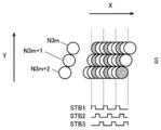
このように隣接するノズルNのノズル位置が主走査方向XにずらされたノズルNの配列を、スタガ配列という。そして、スタガ配列では、3つや4つのノズルNごとにノズル位置がずらされた配列が繰り返されるように構成されることが多く、3つのノズルNごとにずらされる場合、一般的にN3m(m=0、1、2、…。以下同じ。)で表される各ノズルN3mが、主走査方向Xに直交する副走査方向Yに列状に配列され、N3m+1、N3m+2で表される各ノズルN3m+1、N3m+2もそれぞれ副走査方向Yに列状に配列される。
そして、記録媒体Sの画素ピッチをLとした場合、ノズルN3m、N3m+1、N3m+2の各列同士の間隔pは、通常、記録媒体Sの画素ピッチLの1/3または2/3、すなわちL/3または2L/3となるように形成される。また、隣接する各ノズルN同士の副走査方向Yの間隔qは、通常、画素ピッチLと同じになるように形成される。
なお、以下、同じ列に属する各ノズルN3m等を、まとめてノズル列3m等という。すなわち、ノズル番号が3m(m=0、1、2、…)で表される各ノズルN3mで形成されるノズル列をノズル列3mといい、ノズル番号が3m+1で表される各ノズルN3m+1で形成されるノズル列をノズル列3m+1といい、ノズル番号が3m+2で表される各ノズルN3m+2で形成されるノズル列をノズル列3m+2という。
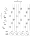
スタガ配列されたノズルNは、通常、多相駆動されるようになっており、図24に示したような3つのノズルNごとにスタガ配列された記録ヘッドHでは、各ノズルN3m、N3m+1、N3m+2が3相駆動される。従来から行われている各ノズルN3m、N3m+1、N3m+2の3相駆動は、以下のようにして行われる。
すなわち、図25に示すように、まず、吐出駆動の位相の切り替えるためのストローブパルスSTB1をノズル列3mの各ノズルN3mに印加し、その状態で図示しないドライブパルスを印加すると、ストローブパルスSTB1が印加されているノズル列3mの各ノズルN3mからインクが記録媒体Sに吐出される。
そして、記録ヘッドHが主走査方向Xに画素ピッチLの1/3だけ移動した時点で、ストローブパルスをSTB1からSTB2に切り替えてノズル列3m+1の各ノズルN3m+1に印加し、その状態でドライブパルスを印加すると、ストローブパルスSTB2が印加されているノズル列3m+1の各ノズルN3m+1からインクが記録媒体Sに吐出される。その際、ノズルN3m+1はノズルN3mよりL/3だけ記録ヘッドHの主走査方向Xへの移動方向のより後方側にあるため、各ノズルN3m+1から吐出されたインクは、記録媒体S上で、各ノズルN3mから吐出され着弾したインクの副走査方向Yに隣接する位置に着弾する。
同様にして、記録ヘッドHがさらに主走査方向Xに画素ピッチLの1/3だけ移動した時点で、ストローブパルスをSTB2からSTB3に切り替えてノズル列3m+2の各ノズルN3m+2に印加した状態でドライブパルスを印加すると、ノズル列3m+2の各ノズルN3m+2からインクが記録媒体Sに吐出され、ノズルN3m+2から吐出されたインクが、記録媒体S上で、各ノズルN3mや各ノズルN3m+1から吐出され着弾したインクの副走査方向Yに隣接する位置に着弾する。
このようにして、ストローブパルスをSTB1→STB2→STB3の順に切り替えて駆動位相の切り替えることで、各ノズルN3m~N3m+2から吐出されたインクを、記録媒体S上の副走査方向Yに延在する直線状に着弾させることができる。なお、上記のように、インクを吐出するノズルNを、記録ヘッドHの主走査方向Xへの移動方向最前部のノズルN3mから後方側のノズルN3m+1、N3m+2に順に切り替えていく駆動位相の切り替え方を順位相という。
また、さらに記録ヘッドHが主走査方向Xに画素ピッチLの1/3だけ移動すると、ノズル列3mの各ノズルN3mは最初にインクを吐出した位置から画素ピッチLだけ主走査方向Xに移動した位置にくる。その時点で、ストローブパルスをSTB3からSTB1に切り替えてノズル列3mの各ノズルN3mに印加した状態でドライブパルスを印加すると、ノズル列3mの各ノズルN3mからは、最初にインクを吐出した位置から画素ピッチLだけ主走査方向Xにずれた位置にインクが吐出される。そのため、ノズル列3mの各ノズルN3mから最初にインクが吐出され記録媒体S上に着弾した位置に隣接する位置にインクが着弾する。
このようにして、記録ヘッドHが主走査方向XにL/3だけ移動するごとにストローブパルスをSTB1からSTB2、STB3と順々に切り替えて、記録媒体S上に、副走査方向Yに延在する直線状にインクを着弾させ、そのインクの直線の主走査方向Xに隣接する位置にさらに直線状にインクを着弾させる。従来のインクジェット記録装置では、このようにして、記録媒体Sに副走査方向Yに延在する直線状にインクを着弾させる動作を繰り返すようにして、記録媒体Sの各画素にそれぞれインクを着弾させて記録媒体S上に画像を記録していた。
なお、図24や図25に示したように、記録ヘッドHが図中右側に移動する場合には、ストローブパルスをSTB1→STB2→STB3の順に切り替えて、インクを吐出するノズルNを、記録ヘッドHの移動方向最前部のノズルN3mから後方側のノズルN3m+1、N3m+2に順に切り替えたが、記録ヘッドHが図中左側に移動しながら画像記録を行う場合には、記録ヘッドHの移動方向最前側のノズルNがノズルN3m+2に代わるため、インクを吐出するノズルNが記録ヘッドHの移動方向最前側のノズルN3m+2から後方側のノズルN3m+1、N3mに順に切り替わるように、ストローブパルスをSTB3→STB2→STB1の順に切り替える。
しかしながら、上記のようにして記録媒体S上に画像を記録する場合、例えば、所定のノズルNにノズル欠が生じる等してそのノズルNからインクが正常に吐出されないと、図26に×印を付して示すように、記録媒体Sに記録された画像中のそのノズルN(図26の例ではノズルN9)に対応する位置に、主走査方向Xに延びる線上にインクが吐出されない部分が生じるため、記録媒体Sに記録された画像に筋状の模様が入ったような状態となり記録画像の画質が低下してしまう。なお、図25に示したようにインクを吐出しないノズルNを記載すると図が煩雑になるため、図26を含めて以下の各図では、記録媒体S上に着弾したインクの位置のみを円で示す。
上記の問題を解決するために、特許文献2に記載のインクジェット記録装置では、記録ヘッドHが例えば図24や図25に示したように図中右側に移動する際に、インクを吐出するノズルNを、記録ヘッドHの主走査方向Xへの移動方向最前部のノズルN3mから後方側のノズルN3m+1、N3m+2に順に切り替えていく代わりに、記録ヘッドHの主走査方向Xへの移動方向最後部のノズルN3m+2から前方側のノズルN3m+1、N3mに順に切り替えるように駆動位相を切り替える、いわゆる逆位相とすることが提案されている。
そして、その際、図27に示すように、記録ヘッドHの主走査方向Xへの移動速度を2倍にして同じノズルNからインクが1画素おきに吐出されるようにする。そして、図28に示すように、スタガ配列のノズルMを有する記録ヘッドH*を記録ヘッドHに主走査方向Xに並設してさらにもう1つ設け、或いは、図29に示すように、スタガ配列のノズルNが設けられた記録ヘッドHにさらにノズルNに主走査方向Xに並設してスタガ配列のノズルMを設けて、ノズルNと同様にノズルMも逆位相で吐出駆動することで、図30に示すように、ノズルNから吐出され記録媒体S上に着弾したインクの間隙部分にノズルMからインクを吐出して着弾させて、記録媒体Sへの画像記録を行う。
このように構成すれば、例えばノズルNの一部にノズル欠が生じる等してそのノズルNからインクが正常に吐出されない場合でも、吐出されなかったインクが本来着弾する位置に隣接する画素位置に、正常なノズルMから吐出されたインクが着弾して埋められる。そのため、図26に示したように、記録媒体Sに記録された画像中にインクが吐出されない部分が主走査方向Xに連続して並ぶことが防止され、画像中に筋状の模様が入ったように見える現象が生じることが回避される。そのため、画質の低下を抑制することが可能となる。
なお、図27(以下の各図においても同様)では、ストローブパルスSTB1~STB3のパルス幅(パルスがハイレベルになっている時間間隔)が図25に示した場合のストローブパルスSTB1~STB3のパルス幅の2倍になったかのように記載されているが、これは記録ヘッドHの移動速度が2倍になったためであり、ストローブパルスSTB1~STB3のパルス幅自体は変わらない。
ところで、特許文献2では、インクジェット記録装置がラインヘッド方式であり、記録媒体が記録ヘッドに対して相対的に1回移動する間に記録媒体の全画素にインクを吐出して画像を記録することが前提となっている。すなわち、いわゆる1パスで画像記録が行われなければならなくなる。
そのため、記録ヘッドの各ノズルを逆位相で吐出駆動し、記録媒体に対する記録ヘッドの移動速度を従来の移動速度の2倍にしたことで、ノズルNからインクが1画素おきに吐出され着弾する、その間隙部分を埋めるために、図28に示したように、スタガ配列のノズルMを有する記録ヘッドを記録ヘッドHに主走査方向Xに並設してさらにもう1つ設けたり、スタガ配列のノズルNが設けられた記録ヘッドHにさらにノズルNに主走査方向Xに並設してスタガ配列のノズルMを設けることが必要になった。
しかし、スタガ配列のノズルNを有する記録ヘッドHと、スタガ配列のノズルMを有する記録ヘッドとを別々に設ける場合、記録ヘッドを新たに設ける分だけコストが増大してしまう。また、各記録ヘッドのノズルN、M同士の位置の調整作業が煩雑になるとともに、ノズルN、Mの吐出タイミングを適切に調整しなければならない等の種々の問題が生じる。また、記録ヘッドHにともにスタガ配列のノズルNとノズルMを設ける場合には、新たにそのような専用の記録ヘッドを製造しなければならないという問題があった。
これらの問題は、インクジェット記録装置がラインヘッド方式であるために1パスで画像記録を行われなければならないという制約のために生じる問題であり、インクジェット記録装置がシリアルヘッド方式である場合には、上記のような問題は生じない。つまり、シリアルヘッド方式のインクジェット記録装置の場合には、複数パスで、すなわち記録ヘッドと記録媒体とが相対的に複数回移動する間に記録媒体の全画素にインクを吐出して画像を記録するように構成することが可能であるため、新たに記録ヘッドを設けたり、専用の記録ヘッドを製造したりする必要がなく、既存の記録ヘッドを用いることが可能である。
そこで、ノズルNがスタガ配列された既存の記録ヘッドを用いたシリアルヘッド方式のインクジェット記録装置において、ノズルNの一部にノズル欠が生じる等して吐出不良が生じても、図26に示したように、記録媒体S上の画像中に筋状の模様が入ったように見えるように記録されることを防止し、記録画像の画質の改善を図ることが可能となるインクジェット記録装置の開発が望まれる。
本発明は、上記の問題点を鑑みてなされたものであり、ノズルがスタガ配列された記録ヘッドを用いたシリアルヘッド方式のインクジェット記録装置において、記録媒体上の画像中に筋状の模様が生じず、記録画像の画質の改善を図ることが可能なインクジェット記録装置を提供することを目的とする。
前述の問題を解決するために、請求項1に記載のインクジェット記録装置は、
3相よりなる駆動位相ごとに駆動され、画素ピッチをLとした場合に、複数個のノズルが主走査方向にL/3間隔でスタガ配列された3列よりなるノズル列を有する記録ヘッドと、
前記記録ヘッドの各ノズル列を、記録媒体に対する前記記録ヘッドの相対的移動方向の最後部のノズル列から前方側のノズル列に順に吐出駆動し、前記記録ヘッドのノズル列ごとの吐出周波数をfとした場合に、前記記録ヘッドを2×L×fの移動速度で主走査方向に移動させて走査させる制御手段と、
を備え、
前記制御手段は、前記記録ヘッドの主走査方向への1回の走査が終了すると、前記記録媒体を前記記録ヘッドに対して主走査方向に直交する副走査方向に前記画素ピッチの所定倍の距離だけ移動させるとともに、次の主走査方向への走査では、前記記録ヘッドのそれまでの走査で前記記録媒体上にインクを着弾させた画素位置以外の画素位置に前記各ノズルからインクを吐出させるように制御して、前記記録媒体の各画素にそれぞれインクを着弾させて前記記録媒体上に画像を記録することを特徴とする。
請求項2に記載の発明は、請求項1に記載のインクジェット記録装置において、前記記録ヘッドは、前記3列よりなるノズル列を2組備え、前記2組のノズル列が主走査方向に並設されており、同じノズル列の組における隣接する前記ノズル同士の副走査方向の間隔が前記画素ピッチの2倍に設定されており、かつ、一方の組のノズル列の前記ノズルが他方の組のノズル列の前記ノズルに対して副走査方向に1画素ピッチ分ずらして設けられていることを特徴とする。
請求項3に記載の発明は、請求項1に記載のインクジェット記録装置において、前記記録ヘッドは、前記3列よりなるノズル列を2組備え、前記2組のノズル列が主走査方向に並設されており、同じノズル列の組における隣接する前記ノズル同士の副走査方向の間隔が前記画素ピッチの4倍に設定されており、かつ、一方の組のノズル列の前記ノズルが他方の組のノズル列の前記ノズルに対して副走査方向に2画素ピッチ分ずらして設けられていることを特徴とする。
請求項4に記載の発明は、請求項1から請求項3のいずれか一項に記載のインクジェット記録装置において、前記制御手段は、前記記録ヘッドの主走査方向への1回の走査の間に行わせる各吐出周期ごとの前記各ノズルからのインクの吐出動作について、前記各ノズルからインクを吐出させる吐出周期と、前記各ノズルからインクを吐出させない吐出周期とを設けることを特徴とする。
請求項1に記載の発明によれば、仮にノズルの一部にノズル欠が生じる等してインクを正常に吐出しないノズルが存在する場合でも、当該ノズルから吐出されなかったインクが本来着弾するはずの画素位置に隣接する画素位置に、別の正常なノズルから吐出されたインクが着弾して埋められるため、記録媒体に記録された画像中にインクが吐出されない部分が主走査方向に連続して並ぶことが防止され、画像中に筋状の模様が入ったように見える現象が生じることが回避される。そのため、画質の低下を抑制し、画質の改善を図ることが可能となる。
また、既存の記録ヘッドを用いて上記の効果を奏することが可能となるため、特許文献2に記載のインクジェット記録装置のように、別の記録ヘッドを並設したり、専用の記録ヘッドを用いたりする必要がなく、インクジェット記録装置の製造コストが増大することを回避して、コストの低減を図ることが可能となる。
さらに、従来の記録手法では、記録ヘッドの1回の走査(いわゆる1パス)で記録媒体上に画像を記録することができ、本発明の記録手法では、記録媒体上に画像を記録するために記録ヘッドの2回の走査(いわゆる2パス)が必要となるが、記録ヘッドの主走査方向への移動速度が従来の移動速度の2倍になるため、画像記録に要する時間は従来の記録手法の場合とさほど変わらない。すなわち、請求項1に記載の発明によれば、従来の記録手法の場合と同等の記録時間で、従来の記録手法では回避できなかった画像中への筋状の模様の混入現象を回避することが可能となる。
請求項2に記載の発明によれば、記録ヘッドとして、3列よりなるノズル列を2組備え、2組のノズル列が主走査方向に並設されており、同じノズル列の組における隣接するノズル同士の副走査方向の間隔が画素ピッチの2倍に設定されており、かつ、一方の組のノズル列のノズルが他方の組のノズル列のノズルに対して副走査方向に1画素ピッチ分ずらして設けられている記録ヘッドを用いた場合にも、前記発明の効果と同様の効果を奏することが可能となる。
請求項3に記載の発明によれば、記録ヘッドとして、3列よりなるノズル列を2組備え、2組のノズル列が主走査方向に並設されており、同じノズル列の組における隣接するノズル同士の副走査方向の間隔が画素ピッチの4倍に設定されており、かつ、一方の組のノズル列のノズルが他方の組のノズル列のノズルに対して副走査方向に2画素ピッチ分ずらして設けられている記録ヘッドを用いた場合にも、前記発明の効果と同様の効果を奏することが可能となる。
請求項4に記載の発明によれば、前記各発明の効果に加え、ノズルの一部にノズル欠が生じる等してインクを正常に吐出しないノズルが存在する場合でも、当該ノズルNからインクが吐出されない画素位置の間の部分の複数の画素位置が、別の複数の正常なノズルから吐出された複数のインクが着弾して埋められるため、インクが吐出されない画素位置が画像中で疎らに拡散された状態となり、記録媒体に記録された画像中に筋状の模様が入ることをより的確に回避することが可能となる。
以下、本発明に係るインクジェット記録装置の実施の形態について、図面を参照して説明する。
[第1の実施の形態]
第1の実施形態に係るインクジェット記録装置1は、図1に示すように、主に、搬送部2と、主走査部3と、コンピュータ4とで構成されている。また、図2は、主走査部3の内部構造のうち、後述する記録ヘッド5を含むキャリッジ32部分の拡大図である。
[第1の実施の形態]
第1の実施形態に係るインクジェット記録装置1は、図1に示すように、主に、搬送部2と、主走査部3と、コンピュータ4とで構成されている。また、図2は、主走査部3の内部構造のうち、後述する記録ヘッド5を含むキャリッジ32部分の拡大図である。
搬送部2の上部には、主走査方向Xに延在する駆動ローラ21と図示しない従動ローラとが回転自在に軸支されており、駆動ローラ21の一端側には、駆動ローラ21を回転駆動するための駆動モータ22が取り付けられている。駆動ローラ21と従動ローラとの間には、無端状の搬送ベルト23が張架されており、搬送ベルト23は、駆動ローラ21が回転すると駆動ローラ21と従動ローラとの間を周回してその上面に載置された記録媒体Sを搬送方向Zに搬送し、駆動ローラ21の回転が停止すると、両ローラ間での周回を停止し、記録媒体Sの搬送を停止するようになっている。
そして、駆動モータ22は、後述する制御手段9の制御に従って、記録ヘッド5が主走査方向Xへの1回の走査が終了すると、駆動ローラ21を所定量だけ回転させて記録媒体Sを搬送方向Zに所定距離だけ搬送させて停止させ、記録ヘッド5が主走査方向Xの反対方向への走査を開始して終了すると、駆動ローラ21を再度所定量だけ回転させて記録媒体Sを搬送方向Zに所定距離だけ搬送させて停止させることを繰り返し、記録媒体Sをいわゆる間欠搬送するようになっている。
なお、記録媒体Sの搬送方向Zは、主走査方向Xに直交する副走査方向Yに平行になるように設定される。また、搬送ベルト23で記録媒体Sを搬送するように構成する必要はなく、例えば、記録媒体Sを平板状のプラテン上を搬送方向Z(副走査方向Y)に移動させるように構成することも可能である。また、記録媒体Sとしては、前述したように、紙や布帛のほか、樹脂フィルムや金属類等を用いることが可能であり、特に限定されない。
搬送部2の搬送ベルト23の上方には、主走査部3が配設されている。主走査部3の内部には、棒状のキャリッジレール31が主走査方向Xに延在するように配設されており、キャリッジレール31には、略筐体状のキャリッジ32が主走査方向Xに往復移動自在に支持されている。キャリッジ32は、図示しないモータを含む走査駆動機構の駆動によりキャリッジレール31に沿って主走査方向Xに移動して走査されるようになっている。
キャリッジ32には、画像記録時にイエロー(Y)、マゼンタ(M)、シアン(C)、ブラック(K)等の各色のインクを吐出する複数のノズルNが記録媒体Sに対向する面P(以下、ノズル面Pという。)に配列された記録ヘッド5が複数搭載されており、各記録ヘッド5のノズルNから搬送ベルト23上の記録媒体Sに対して各色のインクの液滴が吐出されるようになっている。
なお、記録ヘッド5等の構成については後で説明する。また、キャリッジ32には、後述するインクタンク81から記録ヘッド5にインクを供給する図示しない配管や、記録ヘッド5等を駆動するための電気信号や電力を伝達する図示しない配線等が収容されたケーブルベア33が接続されている。
また、本実施形態では、図1に示すように、主走査部3の主走査方向Xの一端側は、記録ヘッド5のメンテナンスを行うためのメンテナンス部6とされており、また、主走査部3の主走査方向Xの他端側は、記録ヘッド5のノズルNが非記録動作時に乾燥してノズルNからのインクの吐出に不具合が生じないように、非記録動作時に記録ヘッド5のノズル面Pをキャップして保湿するためのノズル保湿部7とされている。
さらに、本実施形態では、主走査部3の背後には、各記録ヘッド5にそれぞれ供給する各色のインクを貯蔵するインクタンク81を備えるインクラック8が配置されている。各インクタンク81からは、前述した配管や図示しないインク供給管等を介して各記録ヘッド5にインクがそれぞれ供給されるようになっている。
また、主走査部3の下方には、図示しない外部装置から入力された記録媒体Sに記録すべき画像の画像データを記録ヘッド5の各ノズルNに対応するデータに変換するための画像処理用のコンピュータ4が配設されており、コンピュータ4から前述した配線を介して記録ヘッド5を駆動する図示しないヘッド駆動回路等にデータ等がシリアル転送されるようになっている。なお、本実施形態では、コンピュータ4は、図示しないCPU(Central Processing Unit)やROM(Read Only Memory)、RAM(Random Access Memory)、入出力インターフェース等がバスに接続された汎用のコンピュータで構成されている。
記録ヘッド5としては、図24に示したような複数のノズルN3m、N3m+1、N3m+2が主走査方向XにL/3間隔でスタガ配列された3列のノズル列3m、3m+1、3m+2を有する一般的な記録ヘッドHを用いることも可能であるが、本実施形態では、記録ヘッド5として、図3に示すような既存の記録ヘッドが用いられている。
具体的には、記録ヘッド5は、3相よりなる駆動位相ごとに駆動され、複数のノズルNが主走査方向XにL/3間隔(Lは画素ピッチ)でスタガ配列された3列よりなるノズル列の組が、記録ヘッド5の主走査方向Xに2組並設されている。以下、図中右側の組のノズル列をR3m、R3m+1、R3m+2、ノズル列R3m、R3m+1、R3m+2に属する各ノズルをそれぞれノズルNR3m、NR3m+1、NR3m+2と表し、図中左側の組のノズル列をL3m、L3m+1、L3m+2、ノズル列L3m、L3m+1、L3m+2に属する各ノズルをそれぞれノズルNL3m、NL3m+1、NL3m+2と表す。
本実施形態では、ノズルNは、左右各組ごとに偶数個の256個ずつ、計512個形成されている。また、この記録ヘッド5を用いて記録媒体S上に360dpiの解像度で画像記録を行うようになっており、この場合、画素ピッチLは70.5μmであるから、左右の3列のノズル列同士の間隔pは、その1/3の23.5μmにそれぞれ設定されている。
さらに、左右の対応するノズル列同士の間隔、すなわち、ノズル列R3mとノズル列L3m、ノズル列R3m+1とノズル列L3m+1、ノズル列R3m+2とノズル列L3m+2との間隔は1.44mmに設定されている。また、本実施形態の記録ヘッド5の各ノズル列ごとの吐出周波数(すなわち各ノズルNごとの吐出周波数)fは適宜設定され、例えば6.7kHz程度に設定される。
また、本実施形態の記録ヘッド5では、同じノズル列の組における隣接する各ノズルN同士の副走査方向Yの間隔qは、画素ピッチLの2倍、すなわち141μmに設定されており、左右のノズル列の組では、ノズルNが副走査方向Yに1画素ピッチL分ずらして設けられている。
そのため、仮に、記録ヘッド5をL×fの移動速度で主走査方向Xに移動させて走査させ、本実施形態の記録ヘッド5のノズルNR3m、NR3m+1、NR3m+2およびノズルNL3m、NL3m+1、NL3m+2をそれぞれ図25に示したように順位相で吐出駆動して(すなわち、記録ヘッド5の各ノズル列を、記録媒体Sに対する記録ヘッド5の相対的移動方向(主走査方向X)の最前部のノズル列から後方側のノズル列に順に吐出駆動して)、従来から行われている3相駆動で吐出駆動すると、図4に示すように、記録ヘッド5の主走査方向Xへの1回の走査で、ノズルNR3m~NR3m+2およびノズルNL3m~NL3m+2から吐出されたインクは記録媒体S上で同一の位置に着弾することなく、それぞれ別々の位置に着弾する。
このように、本実施形態の記録ヘッド5は、構造的には、図29に示した特許文献2に記載のインクジェット記録装置に用いられる記録ヘッドHと類似するようにも見えるが、その機能は、図29に示した記録ヘッドHとは異なり、図24に示した複数のノズルN3m、N3m+1、N3m+2が主走査方向XにL/3間隔でスタガ配列された3列のノズル列3m、3m+1、3m+2を有する記録ヘッドHと同様に機能するものである。
そして、図4に示したように、本実施形態の記録ヘッド5は、上記のように従来から行われている3相駆動で吐出駆動する場合には、1回の走査で(すなわち1パスで)記録媒体Sの各画素にそれぞれインクを着弾させて、記録媒体S上に画像を記録することができるようになっている。
しかし、図4に示したように従来から行われている3相駆動の吐出駆動を行うと、図26に示したように、所定のノズルNにノズル欠が生じる等してそのノズルNからインクが正常に吐出されない場合に、記録媒体Sに記録された画像に筋状の模様が入ったような状態となって記録画像の画質が低下することは前述したとおりである。
なお、本実施形態では、図2に示したキャリッジ32の上部には、前述したようにケーブルベア33が連結されているが、図5に示すように、ケーブルベア33に収容された配管34はジョイント35を介してインク供給管36に連結されている。そして、インク供給管36は図5では図示が省略されている各記録ヘッド5に連結されており、インクタンク81(図1参照)から供給された各色のインクがそれぞれ配管34やインク供給管36を介して各記録ヘッド5に供給されるようになっている。
また、本実施形態では、各配管34は所定の本数ごとにそれぞれ樹脂製のチューブ37に収容されており、ケーブルベア33内には、配管34と配線38とが擦れ合わないようにそれらを区画する隔壁39が設けられている。
さらに、配線38は、コネクタ40等を介してヘッド駆動回路51に接続されており、コンピュータ4からシリアル転送されてきたデータ等をヘッド駆動回路51に伝送するようになっている。
ヘッド駆動回路51は、図6に示すように、シフトレジスタ52、ラッチ回路53、レベルシフタ回路56、駆動波形生成部57等で構成されている。ヘッド駆動回路51は、記録ヘッド5の各ノズルNに対応するデータd1、d2、…がコンピュータ4からシリアル転送されてくると、それらのデータd1、d2、…を、クロックCLKにあわせて一旦シフトレジスタ52に順次蓄積する。
そして、各データd1、d2、…、dnがシフトレジスタ52に蓄積された時点でラッチ回路53にラッチ(Latch)信号LATが入力されると、そのタイミングでラッチ回路53がシフトレジスタ52からデータd1、d2、…、dnを取り込み、必要に応じて各データの順番を入れ替える等の処理が適宜行われる。また、空になったシフトレジスタ52には、次の一連のデータが順次蓄積されていく。
そして、ラッチ回路53から出力されたデータd1、d2、…、dnは比較部54に送信され、ストローブクロックSTBCLKにあわせて比較部54から順次出力され、比較部54から出力されたデータd1、d2、…、dnはそれぞれ各アンド回路55に送られる。アンド回路55では、比較部54から出力されたデータdおよびストローブパルスSTB1、STB2、STB3のいずれかがONのとき、ONのストローブパルスSTBが入力されているアンド回路55からレベルシフタ回路56にデータdが送信される。
なお、図25や図27に示したものと同様に、本実施形態においても、ストローブパルスSTB1がハイレベルになっている場合にはノズルNR3m、NL3m(図3参照)から、ストローブパルスSTB2がハイレベルになっている場合にはノズルNR3m+1、NL3m+1から、ストローブパルスSTB3がハイレベルになっている場合にはノズルNR3m+2、NL3m+2からそれぞれインクが吐出されるようになっている。
そして、後述するように、ストローブパルスSTB1、STB2、STB3が順位相或いは逆位相で切り替えられることにより、記録ヘッド5のノズルNR3m、NR3m+1、NR3m+2およびノズルNL3m、NL3m+1、NL3m+2が順位相或いは逆位相で3相駆動されるようになっている。
レベルシフタ回路56は、電圧の上下にあわせて各データd1、d2、…、dnを駆動波形生成部57に送るようになっており、駆動波形生成部57では、データd1、d2、…に基づいて例えば図7のような駆動波形を有するノズル駆動信号D1、D2、…、Dnを生成して、各出力端子58を介して各記録ヘッド5の各ノズルNにそれぞれノズル駆動信号D1、D2、…、Dnを順次送信するようになっている。
また、前述したように、記録ヘッド5の各ノズルNは3相駆動され、ハイレベルのストローブパルスSTBが印加されている状態で上記のノズル駆動信号Dが印加されると、そのノズルNの図示しないピエゾ素子がノズル駆動信号Dの駆動波形に従って変形してノズルNからそれぞれインクが吐出されるようになっている。
図8は、本実施形態に係るインクジェット記録装置の制御構成を示すブロック図である。インクジェット記録装置1は、制御手段9を備えている。制御手段9は、前述したコンピュータ4中に構成することも可能であるが、コンピュータ4とは別体の汎用コンピュータや専用のプロセッサ(processor)を有するマイクロコンピュータ等で構成することも可能である。
制御手段9は、装置の各機能部の動作を制御するものであり、例えば、走査駆動機構10を駆動させて、キャリッジ32(図1、図2参照)をキャリッジレール31に沿って主走査方向Xに移動させるとともに、前述したように、キャリッジ32の移動に伴って記録媒体Sの上方を走査される各記録ヘッド5の主走査方向Xの走査にあわせて駆動モータ22を駆動させ、搬送ベルト23を搬送方向Z(副走査方向Y)に間欠的に移動させて、記録媒体Sを間欠搬送させるようになっている。
また、制御手段9は、インク供給系に設けられたポンプ11を適宜駆動させて、インクタンク81から配管34やインク供給管36を介して各記録ヘッド5にインクを供給するようになっている。さらに、制御手段9には、マウスやキーボード、タッチパネル等の図示しない入力手段が設けられており、前述した記録ヘッド5の各ノズル列ごとの吐出周波数f等を設定することができるようになっている。
さらに、制御手段9は、コンピュータ4を制御して、図6に示したように、ヘッド駆動回路51に対して、当該ヘッド駆動回路51が担当する各記録ヘッド5の各ノズルNに対応する各データd1、d2、…を所定のタイミングでシリアル転送させるようになっている。
一方、制御手段9は、従来の記録手法のように、記録ヘッド5をL×fの移動速度で主走査方向Xに走査させ、記録ヘッド5のノズル列R3m、R3m+1、R3m+2およびノズル列L3m、L3m+1、L3m+2の各ノズルNの駆動位相を順位相で切り替えるか、或いは、記録ヘッド5の移動速度を従来の2倍、すなわち2×L×fで主走査方向Xに走査させ、記録ヘッド5のノズル列R3m、R3m+1、R3m+2およびノズル列L3m、L3m+1、L3m+2の各ノズルNの駆動位相を逆位相で切り替えるかのいずれかを入力手段を介して指定することができるようになっている。
前者の従来の記録手法が指定されると、制御手段9は、走査駆動機構10に対して、記録ヘッド5を搭載するキャリッジ32の主走査方向Xへの移動速度をL×fに設定し、また、ヘッド駆動回路51に対して、記録ヘッド5のノズル列R3m~R3m+2およびノズル列L3m~L3m+2を記録媒体Sに対する記録ヘッド5の相対的移動方向(主走査方向X)の最前部のノズル列から後方側のノズル列に順に吐出駆動するように(すなわち順位相で吐出駆動するように)設定するようになっている。
記録ヘッド5のノズル列R3m~R3m+2およびノズル列L3m~L3m+2を順位相で吐出駆動する場合、前述したように、図3に示した記録ヘッド5が主走査方向Xの1回走査される際、例えば図中右側に走査される際には、各ノズルNに印加するストローブパルスSTBがSTB1→STB2→STB3の順で切り替えられ、記録ヘッド5が主走査方向Xの反対方向に走査される際、例えば図中左側に走査される際には、各ノズルNに印加するストローブパルスSTBがSTB3→STB2→STB1の順で切り替えられる。
そして、上記のような設定が行われると、記録動作時には、記録ヘッド5は主走査方向XにL×fの移動速度で移動して走査し、記録ヘッド5のノズル列R3m~R3m+2およびノズル列L3m~L3m+2の各ノズルNR3m~NR3m+2、NL3m~NL3m+2からは、図4に示したように、各ノズルNに対応する記録媒体Sの画素位置にインクがそれぞれ吐出され、それらの主走査方向Xに隣接する画素に次々とインクが吐出されて記録媒体S上に画像が記録される。
一方、後者の記録手法が指定された場合が本発明における記録手法であり、以下、この場合における制御手段9による制御について説明する。また、あわせて本実施形態に係るインクジェット記録装置1の作用について説明する。
なお、図3に示したような左右各組ごとに256個ずつ、計512個のノズルNを記載すると図が煩雑になるため、図4を含めて以下の図9~図15の各図では、左右各組毎に6個ずつ、計12個のノズル(NL0~NL5及びNR0~NR5)で画像記録するものとして説明する。
本発明の記録手法である後者の記録手法が指定されると、制御手段9は、走査駆動機構10に対して、記録ヘッド5を搭載するキャリッジ32の主走査方向Xへの移動速度を2×L×fに設定し、また、ヘッド駆動回路51に対して、記録ヘッド5のノズル列R3m~R3m+2およびノズル列L3m~L3m+2を記録媒体Sに対する記録ヘッド5の相対的移動方向(主走査方向X)の最後部のノズル列から前方側のノズル列に順に吐出駆動する(すなわち逆位相で吐出駆動する)ように設定する。
記録ヘッド5のノズル列R3m~R3m+2およびノズル列L3m~L3m+2を逆位相で吐出駆動する場合、図3に示した記録ヘッド5が主走査方向Xに1回走査される際、例えば図中右側に走査される際には、各ノズルNに印加するストローブパルスSTBがSTB3→STB2→STB1の順で切り替えられ、記録ヘッド5が主走査方向Xの反対方向に走査される際、例えば図中左側に走査される際には、各ノズルNに印加するストローブパルスSTBがSTB1→STB2→STB3の順で切り替えられる。
このように設定されると、記録動作時には、キャリッジレール31に沿った主走査方向Xへのキャリッジ32の移動に伴って、記録ヘッド5は、主走査方向Xに2×L×fの移動速度で移動して走査する。
また、図27に示した例と同様に、記録ヘッド5のノズル列R3m、R3m+1、R3m+2の各ノズルNR3m、NR3m+1、NR3m+2からは、図9に示すように、それぞれ対応する記録媒体Sの画素位置に主走査方向Xに1画素おきにインクが吐出される。また、前述したように、各ノズルNR3m、NR3m+1、NR3m+2は隣接するノズルN同士の副走査方向Yの間隔qが画素ピッチLの2倍に設定されているため、副走査方向Yにも1画素おきにインクが吐出される。
また、記録ヘッド5のノズル列L3m、L3m+1、L3m+2の各ノズルNL3m、NL3m+1、NL3m+2からも同様にインクが吐出されるが、ノズルNL3m、NL3m+1、NL3m+2はノズルNR3m、NR3m+1、NR3m+2に対して副走査方向Yに1画素ピッチL分だけずらして設けられているため、図10に示すように、各ノズルNL3m、NL3m+1、NL3m+2からは、各ノズルNR3m、NR3m+1、NR3m+2からインクが吐出された画素位置の副走査方向Yに隣接する画素位置にインクが吐出される。
その際、記録ヘッド5の主走査方向Xへの1回の走査が終了した後、記録媒体Sを搬送方向Z(副走査方向Y)に搬送せずに、記録ヘッド5を主走査方向Xの反対方向に走査しながら各ノズルNからインクを吐出したのでは、結局、図4に示した場合と同様に、同一のノズルNから吐出されたインクが記録媒体S上の副走査方向の同じ位置に吐出される。そのため、ノズルNの一部にノズル欠が生じる等して吐出不良が生じていると、記録媒体Sに記録された画像中のそのノズルNに対応する位置に、主走査方向Xに延在する筋状の模様が入った状態となってしまう。
そこで、本発明では、制御手段9は、記録ヘッド5の主走査方向Xへの1回の走査が終了すると、駆動モータ22を駆動して記録媒体Sを搬送方向Z(副走査方向Y)に画素ピッチの所定倍の距離だけ移動させて停止させ、次の記録ヘッド5の主走査方向Xの反対方向への走査では、記録ヘッド5のそれまでの走査で記録媒体S上にインクを着弾させた画素位置以外の画素位置に各ノズルからインクを吐出させる。
例えば、記録ヘッド5の主走査方向Xへの1回の走査で、図10に示した記録媒体S上の画素位置にインクが吐出された場合、制御手段9は、記録媒体Sを副走査方向Y(例えば図中上方向)に画素ピッチの例えば6倍の距離だけ移動させて停止させ、次の記録ヘッド5の主走査方向Xの反対方向への走査では、図11に示すように、記録ヘッド5の前回の走査で記録媒体S上にインクを着弾させた画素位置に隣接する画素位置に各ノズルからインクを吐出させる。なお、記録媒体Sを副走査方向Yに何画素ピッチ分の距離だけ移動させるかは適宜設定される。
この移動距離をW1としたとき、本実施形態においては、いわゆるマルチパス記録を行うものであるので、W1<W2×ノズル数を満足するように移動距離W1を適宜設定することが好ましい。なお、W2は記録ヘッドにおける隣接するノズルN同士の副走査方向Yの間隔であり、具体的には、例えばNL0とNR0の間隔である。
また、W2が画素ピッチの1倍である場合は、マルチパスの回数をW3としたとき、W1=ノズル数×W2/W3を満たすようにW1を設定することが好ましい。
本実施形態では、図11に示すように、W2は画素ピッチの1倍、ノズルの数は12であり、後述するようにマルチパスの回数W3が2であるので、移動距離W1は画素ピッチの6倍としている。
このように、上記の例では記録ヘッド5の2回の走査で(すなわち2パスで)、記録媒体Sの各画素にそれぞれインクを着弾させて記録媒体S上に画像を記録することが可能となる。
また、その際、図11に示したように、記録ヘッド5の同一のノズルNから吐出されたインクが少なくとも記録媒体S上の隣接する画素位置に着弾することがない。そのため、ノズルNの一部にノズル欠が生じる等してインクを正常に吐出しないノズルNが存在する場合でも、図12に示すように、当該ノズルNから吐出されなかったインクが本来着弾するはずの画素位置に隣接する画素位置に、別の正常なノズルNから吐出されたインクが着弾して埋められるため、記録媒体Sに記録された画像中にインクが吐出されない部分が主走査方向Xに連続して並ぶことが防止され、画像中に筋状の模様が入ったように見える現象が生じることが回避され、画質の低下を抑制することが可能となる。
なお、本発明の記録手法のように、記録ヘッド5を主走査方向Xに2×L×fの移動速度で走査し、記録ヘッド5のノズル列R3m~R3m+2およびノズル列L3m~L3m+2を逆位相で吐出駆動する場合、記録ヘッド5の各ノズルNから吐出され記録媒体S上に着弾されるインクの画素位置は、例えば図10や図11に示したように、散在した画素位置になる。そのため、コンピュータ4からヘッド駆動回路51に記録ヘッド5の各ノズルNに対応する各データをシリアル転送する際のデータの配列順を適宜組み替える必要がある。
上記の例では、図11から分かるように、記録媒体Sに記録される画像は、主走査方向Xに延在するインクL3、L0、L3、L0、L3、L0、…で表される画素列を上端とし、副走査方向Yに延在するインクL3、R3、L1、R1、L5、R5、…で表される画素列を左端とする範囲となる。そこで、図13に示すように、上記の画像の左上隅のインクL3の画素位置を基準として、主走査方向Xに平行にx軸を設定し、副走査方向Yに平行にy軸を設定し、記録媒体Sに記録される画像の各画素位置を座標(x,y)で表す。また、座標(x,y)で表される画素位置にインクを吐出するノズルNに対応するデータをd(x,y)で表すとする。
コンピュータ4は、図示しない外部装置から入力された記録媒体Sに記録すべき画像の画像データを記録ヘッド5の各ノズルNに対応する形に変換した各データd(x,y)をRAM上に展開する。そして、例えば図10に示したように各ノズルNからインクを吐出させる場合、まず、最初の吐出周期でノズルNR0、NR1、NR2、NR3、NR4、NR5、…から吐出されるインクは図14に示すR0、R1、R2、R3、R4、R5、…の各画素位置に着弾するため、コンピュータ4は、ノズルNR0、NR1、NR2、NR3、NR4、NR5、…に、それぞれ0、0、0、d(0,1)、0、0、…の各データを順に対応付けて配列する。
同様にして、コンピュータ4は、ノズルNL0、NL1、NL2、NL3、NL4、NL5、…に、それぞれ0、0、0、d(0,0)、0、0、…の各データを順に対応付けて配列する。そして、各データを連結して0、0、0、d(0,1)、0、0、…、0、0、0、d(0,0)、0、0、…の形に配列する。なお、値が0のデータは、いわゆるダミーデータであり、インクを吐出しないことを表す。
また、次の吐出周期でノズルNR0、NR1、…、NL0、NL1、…から吐出されるインクは図15に示すR0、R1、…、L0、L1、…の各画素位置に着弾するため、コンピュータ4は、ノズルNR0、NR1、NR2、NR3、NR4、NR5、…にそれぞれ0、0、0、d(2,1)、d(1,3)、d(0,5)、…の各データを順に対応付けて配列し、ノズルNL0、NL1、NL2、NL3、NL4、NL5、…にそれぞれ0、0、0、d(2,0)、d(1,2)、d(0,4)、…の各データを順に対応付けて配列して連結する。
このようして、コンピュータ4は、各吐出周期ごとにノズルNR0、NR1、…、NL0、NL1、…から吐出されるインクが着弾する記録媒体Sの各画素位置に対応するデータd(x,y)、或いは対応する画素位置にデータがない場合にはダミーデータである0を対応付けて各データを配列し、適切な配列順のデータ列を作成してヘッド駆動回路51にシリアル転送する。なお、データ列の作成は、記録動作が開始される前に予め行っておいてもよく、また、記録動作と並行して行うように構成することも可能である。
なお、上記のような制御手段9における処理やコンピュータ4における処理は、図3に示した記録ヘッド5に特有の処理ではなく、記録ヘッドとして、例えば図24に示したような一般的な記録ヘッドHを用いた場合にも同様に行うことができる。
以上のように、本実施形態に係るインクジェット記録装置1によれば、ノズルNがスタガ配列された記録ヘッド5や記録ヘッドHを用いたシリアルヘッド方式のインクジェット記録装置において、記録ヘッド5、Hを従来の移動速度(L×f)の2倍の移動速度(2×L×f)で移動させて走査させ、記録ヘッド5、Hの各ノズル列を、記録媒体Sに対する記録ヘッド5、Hの相対的移動方向(主走査方向X)の最後部のノズル列から前方側のノズル列に順に吐出駆動する。すなわち、逆位相で吐出駆動する。
さらに、記録ヘッド5、Hの主走査方向Xへの1回の走査が終了すると、記録媒体Sを記録ヘッド5、Hに対して副走査方向Yに画素ピッチLの所定倍の距離だけ移動させて次の走査を行わせ、記録ヘッド5、Hのそれまでの走査で記録媒体S上にインクを着弾させた画素位置以外の画素位置に各ノズルNからインクを吐出させるように構成した。
そのため、仮にノズルNの一部にノズル欠が生じる等してインクを正常に吐出しないノズルNが存在する場合でも、当該ノズルNから吐出されなかったインクが本来着弾するはずの画素位置に隣接する画素位置に、別の正常なノズルNから吐出されたインクが着弾して埋められるため、記録媒体Sに記録された画像中にインクが吐出されない部分が主走査方向Xに連続して並ぶことが防止され、画像中に筋状の模様が入ったように見える現象が生じることが回避される。そのため、画質の低下を抑制し、画質の改善を図ることが可能となる。
また、図3に示した記録ヘッド5や図24に示した記録ヘッドHなど既存の記録ヘッドを用いて上記の効果を奏することが可能となるため、特許文献2に記載のインクジェット記録装置のように、別の記録ヘッドを並設したり、専用の記録ヘッドを用いたりする必要がなく、インクジェット記録装置1の製造コストが増大することを回避して、コストの低減を図ることが可能となる。
さらに、図4に示した従来の記録手法では、記録ヘッド5、Hの1回の走査(いわゆる1パス)で記録媒体S上に画像を記録することができたが、図11に示した本発明の記録手法では、記録媒体S上に画像を記録するためには、記録ヘッド5、Hの2回の走査(いわゆる2パス)が必要となる。
しかし、記録ヘッド5、Hの主走査方向Xへの移動速度が従来の移動速度の2倍になるため、画像記録に要する時間は従来の記録手法の場合とさほど変わらない。すなわち、本発明によれば、従来の記録手法の場合と同等の記録時間で、従来の記録手法では回避できなかった画像中への筋状の模様の混入現象を回避することが可能となる。
なお、本実施形態に係る記録ヘッド5(図3参照)では、前述したように、左右の対応するノズル列同士の間隔、すなわちノズル列R3mとノズル列L3mとの間隔が1.44mmに設定されているが、画素ピッチLが70.5μmであるため、この間隔は約20.4画素に対応する。
このように、ノズル列R3mとノズル列L3mとの間隔が画素ピッチLの整数倍に設定されていないため、例えば、ノズル列R3m~R3m+2とノズル列L3m~L3m+2との吐出タイミングを同期させて各ノズルNからインクを吐出させた場合、ノズル列R3m~R3m+2の各ノズルNから吐出されたインクとノズル列L3m~L3m+2の各ノズルNから吐出されたインクとの記録媒体S上での着弾位置が、図10や図11に示したように副走査方向Yに揃わないことになる。
この状態を回避するためには、例えば、ノズル列R3m~R3m+2とノズル列L3m~L3m+2との吐出タイミングを同期させずに、それぞれ独立の吐出タイミングで各ノズルNからインクを吐出させるように構成することが可能である。
しかし、ノズル列R3m~R3m+2とノズル列L3m~L3m+2との各ノズルNを独立の吐出タイミングで吐出駆動するように構成されていない場合もある。そのような場合には、記録ヘッド5の各ノズル列ごとの吐出周波数(すなわち各ノズルNごとの吐出周波数)fを調整して、ノズル列R3m~R3m+2の各ノズルNから吐出されたインクとノズル列L3m~L3m+2の各ノズルNから吐出されたインクとの記録媒体S上での着弾位置を副走査方向Yに揃えることが可能である。なお、その場合、記録ヘッド5の移動速度(2×L×f)も吐出周波数fの変化にあわせて変化する。
[第2の実施の形態]
第2の実施形態に係るインクジェット記録装置では、記録ヘッド5として、より解像度が高い画像を記録することができる記録ヘッド5を用いた場合について説明する。
[第2の実施の形態]
第2の実施形態に係るインクジェット記録装置では、記録ヘッド5として、より解像度が高い画像を記録することができる記録ヘッド5を用いた場合について説明する。
具体的には、記録ヘッド5(図3参照)は、3相よりなる駆動位相ごとに駆動され、複数のノズルNが主走査方向XにL/3間隔(Lは画素ピッチ)でスタガ配列された3列よりなるノズル列の組が、記録ヘッド5の主走査方向Xに2組並設されている点では第1の実施形態の場合と同様であり、ノズルNが左右各組ごとに256個ずつ、計512個形成されているが、本実施形態では、この記録ヘッド5を用いて記録媒体S上に720dpiの解像度、すなわち第1の実施形態の場合の倍の解像度で画像記録を行うようになっている。
そのため、画素ピッチLは35.3μmであり、左右の3列のノズル列同士の間隔pは、その1/3の11.8μmにそれぞれ設定されている。なお、左右の対応するノズル列同士の間隔、すなわち、ノズル列R3mとノズル列L3mとの間隔は1.44mmであり、各ノズル列ごとの吐出周波数(すなわち各ノズルNごとの吐出周波数)fが例えば6.7kHz程度に設定される点は第1の実施形態と同様である。
また、本実施形態の記録ヘッド5では、同じノズル列の組における隣接する各ノズルN同士の副走査方向Yの間隔qは、画素ピッチLの4倍に設定されており、左右のノズル列の組では、ノズルNが副走査方向Yに2画素ピッチL分ずらして設けられている。この点でも第1の実施形態と異なる。
そのため、仮に、記録ヘッド5をL×fの移動速度で主走査方向Xに移動させて走査させ、本実施形態の記録ヘッド5のノズルNR3m、NR3m+1、NR3m+2およびノズルNL3m、NL3m+1、NL3m+2をそれぞれ図25に示したように順位相で吐出駆動して、従来から行われている3相駆動で吐出駆動すると、図16に示すように、記録ヘッド5の主走査方向Xへの1回の走査で、ノズルNR3m~NR3m+2およびノズルNL3m~NL3m+2の各ノズルNから吐出されたインクは、副走査方向Yに1画素おきに着弾する。
そして、図16に示すように、本実施形態では、記録ヘッド5は、上記のように従来から行われている3相駆動で吐出駆動する場合には、2回の走査で(すなわち2パスで)記録媒体Sの各画素にそれぞれインクを着弾させて、記録媒体S上に画像を記録するようになっている。
しかし、この場合も、所定のノズルNにノズル欠が生じる等してそのノズルNからインクが正常に吐出されない場合には、記録媒体Sに記録された画像中にインクが吐出されない部分が主走査方向Xに連続して並ぶため、記録媒体Sに記録された画像に筋状の模様が入ったような状態となって記録画像の画質が低下する。
そのため、本実施形態においても、上記の本発明の記録手法が採用され、制御手段9は、走査駆動機構10に対して、記録ヘッド5を搭載するキャリッジ32の主走査方向Xへの移動速度を2×L×fに設定し、また、ヘッド駆動回路51に対して、記録ヘッド5のノズル列R3m~R3m+2およびノズル列L3m~L3m+2を記録媒体Sに対する記録ヘッド5の相対的移動方向(主走査方向X)の最後部のノズル列から前方側のノズル列に順に吐出駆動する(すなわち逆位相で吐出駆動する)ように設定する。
このように設定されると、記録動作時には、キャリッジレール31に沿った主走査方向Xへのキャリッジ32の移動に伴って、記録ヘッド5は、主走査方向Xに2×L×fの移動速度で移動して走査し、記録ヘッド5のノズル列R3m、R3m+1、R3m+2の各ノズルNR3m、NR3m+1、NR3m+2からは、図17に示すように、それぞれ対応する記録媒体Sの画素位置に主走査方向Xに1画素おきにインクが吐出される。
なお、図3に示したような左右各組ごとに256個ずつ、計512個のノズルNを記載すると図が煩雑になるため、図17を含めて以下の図18~図19の各図では、左右各組毎に12個ずつ、計24個のノズル(NL0~NL11及びNR0~NR11)で画像記録するものとして説明する。
また、前述したように、本実施形態では、各ノズルNR3m、NR3m+1、NR3m+2は隣接するノズルN同士の副走査方向Yの間隔qが画素ピッチLの4倍に設定されているため、副走査方向Yには3画素おきにインクが吐出される。
また、記録ヘッド5のノズル列L3m、L3m+1、L3m+2の各ノズルNL3m、NL3m+1、NL3m+2からも同様にインクが吐出されるが、ノズルNL3m、NL3m+1、NL3m+2はノズルNR3m、NR3m+1、NR3m+2に対して副走査方向Yに2画素ピッチ分だけずらして設けられている。そのため、図18に示すように、各ノズルNL3m、NL3m+1、NL3m+2からは、各ノズルNR3m、NR3m+1、NR3m+2からインクが吐出された画素位置の副走査方向Yに1画素おきに隣接する画素位置にインクが吐出される。
そして、本実施形態においても、制御手段9は、記録ヘッド5の主走査方向Xへの1回の走査が終了すると、駆動モータ22を駆動して記録媒体Sを搬送方向Z(副走査方向Y)に画素ピッチの所定倍の距離だけ移動させて停止させ、次の記録ヘッド5の主走査方向Xの反対方向への走査では、記録ヘッド5のそれまでの走査で記録媒体S上にインクを着弾させた画素位置以外の画素位置に各ノズルからインクを吐出させる。
例えば、記録ヘッド5の主走査方向Xへの1回の走査で、図18に示した記録媒体S上の画素位置にインクが吐出された場合、制御手段9は、記録媒体Sを副走査方向Y(例えば図中上方向)に画素ピッチの例えば13倍の距離だけ移動させて停止させ、次の記録ヘッド5の主走査方向Xの反対方向への走査では、図19に示すように、記録ヘッド5の前回の走査で記録媒体S上にインクを着弾させた画素位置の図中右下の画素位置に各ノズルからインクを吐出させる。
本実施形態では、図19に示すように、W2は画素ピッチの2倍、ノズルの数は24であり、後述するマルチパスの回数W3が4であるので、移動距離W1を前述の式W1=ノズル数×W2/W3から算出すると、画素ピッチの12倍となる。
しかしながら、W2が画素ピッチの2倍以上の場合は、副走査方向Yに隣接するノズルN間の画素を記録する必要があるため、算出された画素ピッチの12倍に対して適宜増減しながらW1を設定する必要がある。
本実施形態では、上記のように2回目の走査では、前回の走査で記録媒体S上にインクを着弾させた画素位置の図中右下の画素位置に各ノズルからインクを吐出させるため、W1を画素ピッチの13倍としている。
しかし、第1の実施形態における図11に示した場合と異なり、本実施形態では、図19に示されるように、記録ヘッド5の2回の走査(すなわち2パス)では記録媒体Sの全画素にインクを着弾させることができない。
そこで、本実施形態では、記録ヘッド5の2回目の走査が終了すると、制御手段9は、再度、記録媒体Sを副走査方向Y(例えば図中上方向)に画素ピッチの11倍の距離だけ移動させて停止させて、記録ヘッド5の3回目の走査を行わせ、記録ヘッド5の3回目の走査では、最初の走査で記録媒体S上にインクを着弾させた画素位置の図中右側の画素位置に各ノズルからインクを吐出させる。
そして、記録ヘッド5の3回目の走査が終了すると、制御手段9は、さらに、記録媒体Sを副走査方向Y(例えば図中上方向)に画素ピッチの13倍の距離だけ移動させて停止させて、記録ヘッド5の4回目の走査を行わせ、記録ヘッド5の4回目の走査では、最初の走査で記録媒体S上にインクを着弾させた画素位置の図中下側の画素位置に各ノズルからインクを吐出させる。
このように、本実施形態では、記録ヘッド5の4回の走査で(すなわち4パスで)、記録媒体Sの各画素にそれぞれインクを着弾させて記録媒体S上に画像を記録することが可能となる。
また、その際、図19に示したように、記録ヘッド5の同一のノズルNから吐出されたインクが少なくとも記録媒体S上の隣接する画素位置に着弾することが回避される。そして、第1の実施形態の場合(図12参照)と同様に、ノズルNの一部にノズル欠が生じる等してインクを正常に吐出しないノズルNが存在する場合でも、当該ノズルNから吐出されなかったインクが本来着弾するはずの画素位置に隣接する画素位置に、別の正常なノズルNから吐出されたインクが着弾して埋められる。
そのため、記録媒体Sに記録された画像中にインクが吐出されない部分が主走査方向Xに連続して並ぶことが防止され、画像中に筋状の模様が入ったように見える現象が生じることが回避される。そのため、画質の低下を抑制することが可能となる。
以上のように、本実施形態においても、第1の実施形態に係るインクジェット記録装置1と全く同様の効果を奏することが可能となる。
また、本実施形態では、図16に示した従来の記録手法を採用した場合には、前述したように、記録ヘッド5の2回の走査(いわゆる2パス)で記録媒体S上に画像を記録することができたが、図18に示した本発明の記録手法では、記録媒体S上に画像を記録するためには、記録ヘッド5の4回の走査(いわゆる4パス)が必要となる。
しかし、記録ヘッド5の主走査方向Xへの移動速度が従来の移動速度の2倍になるため、画像記録に要する時間は従来の記録手法の場合とさほど変わらない。すなわち、本実施形態においても、従来の記録手法の場合と同等の記録時間で、従来の記録手法では回避できなかった画像中への筋状の模様の混入現象を回避することが可能となる。
[第3の実施の形態]
ところで、上記の第1および第2の実施形態では、図12に示したように、1つのノズルNから主走査方向Xに1画素おきにインクを吐出し、他のノズルNでその間隙部分の画素位置を埋めるようにインクを吐出するように構成し、すなわち、2つのノズルNから吐出されたインクが主走査方向Xに交互に並ぶようにインクを吐出させる。
[第3の実施の形態]
ところで、上記の第1および第2の実施形態では、図12に示したように、1つのノズルNから主走査方向Xに1画素おきにインクを吐出し、他のノズルNでその間隙部分の画素位置を埋めるようにインクを吐出するように構成し、すなわち、2つのノズルNから吐出されたインクが主走査方向Xに交互に並ぶようにインクを吐出させる。
そして、このように構成することで、仮にノズルNの一部にノズル欠が生じる等してインクを正常に吐出しないノズルNが存在する場合でも、記録媒体Sに記録された画像中に、インクが吐出されない部分が主走査方向Xに連続して並んで筋状の模様が入ったように見える現象が生じることを回避した。
この考え方をさらに拡張すると、1つのノズルNから吐出するインクを、主走査方向Xに1画素おきではなく、さらに間隔をあけて記録媒体Sに着弾させ、その間隙部分の画素位置を他のノズルNから吐出されたインクで埋めるように構成すれば、異常なノズルNからインクが吐出されない画素位置が画像中でより拡散された状態とすることが可能となり、記録媒体Sに記録された画像中に筋状の模様が入ることをより的確に回避することが可能となる。
そこで、第3の実施形態に係るインクジェット記録装置では、制御手段9は、記録ヘッド5の主走査方向Xへの1回の走査の間に行わせる各吐出周期ごとの各ノズルNからのインクの吐出動作について、各ノズルNからインクを吐出させる吐出周期と、各ノズルNからインクを吐出させない吐出周期とを設けるようになっている。
以下、記録ヘッド5として、第1の実施形態に係るインクジェット記録装置1に用いられた記録ヘッド5(図3参照)を用いる場合について説明するが、第2の実施形態で用いられた記録ヘッド5を用いる場合についても同様に適用される。
具体的には、まず、本実施形態においても、上記の第1および第2の実施形態の場合と同様に本発明の記録手法が採用される。すなわち、制御手段9は、記録ヘッド5を主走査方向Xに2×L×fの移動速度で移動させて走査させるとともに、記録ヘッド5のノズル列R3m~R3m+2およびノズル列L3m~L3m+2を逆位相で吐出駆動させる。
また、記録ヘッド5の主走査方向Xへの1回の走査が終了すると、記録媒体Sを搬送方向Z(副走査方向Y)に画素ピッチの所定倍の距離だけ移動させる点も上記の第1および第2の実施形態の場合と同様である。
しかし、本実施形態においては、制御手段9は、記録ヘッド5の主走査方向Xへの1回の走査の間に行わせる各吐出周期ごとの各ノズルNからのインクの吐出動作について、各ノズルNからインクを吐出させる吐出周期と各ノズルNからインクを吐出させない吐出周期とを、1吐出周期ごとに繰り返すように設定することができるように構成されている。
なお、インクを吐出させない吐出周期を設けるか否か、すなわち第3の実施形態を実施するか否かは、ユーザの設定入力に従って設定されるようになっている。また、各ノズルNからインクを吐出させる吐出周期と各ノズルNからインクを吐出させない吐出周期とをどのように設定するかは、予め、或いは上記のユーザによる設定入力の際に適宜設定される。
このような設定の下では、記録ヘッド5のノズル列R3m、R3m+1、R3m+2の各ノズルNR3m、NR3m+1、NR3m+2からは、図20に示すように、最初の吐出周期では対応する記録媒体Sの画素位置にインクが吐出され、次の吐出周期ではインクが吐出されない。
なお、図3に示したような左右各組ごとに256個ずつ、計512個のノズルNを記載すると図が煩雑になるため、図20を含めて以下の図21~図23の各図では、左右各組毎に12個ずつ、計24個のノズル(NL0~NL11及びNR0~NR11)で画像記録するものとして説明する。
この吐出動作を吐出周期ごとに繰り返すことにより、各ノズルNR3m、NR3m+1、NR3m+2にそれぞれ対応する記録媒体Sの画素位置に、主走査方向Xに3画素おきにインクが吐出される。また、各ノズルNR3m、NR3m+1、NR3m+2は隣接するノズルN同士の副走査方向Yの間隔qが画素ピッチLの2倍に設定されているため、副走査方向Yには1画素おきにインクが吐出される。
また、記録ヘッド5のノズル列L3m、L3m+1、L3m+2の各ノズルNL3m、NL3m+1、NL3m+2からも同様にインクが吐出されるが、ノズルNL3m、NL3m+1、NL3m+2はノズルNR3m、NR3m+1、NR3m+2に対して副走査方向Yに1画素ピッチL分だけずらして設けられている。そのため、図21に示すように、各ノズルNL3m、NL3m+1、NL3m+2からは、各ノズルNR3m、NR3m+1、NR3m+2からインクが吐出された画素位置の副走査方向Yに隣接する画素位置にインクが吐出される。
そして、制御手段9は、記録ヘッド5の主走査方向Xへの1回の走査が終了すると、駆動モータ22を駆動して記録媒体Sを搬送方向Z(副走査方向Y)に画素ピッチの所定倍の距離だけ移動させて停止させ、記録ヘッド5を主走査方向Xの反対方向に走査させる。
例えば、記録ヘッド5の主走査方向Xへの1回の走査で、図21に示した記録媒体S上の画素位置にインクが吐出された場合、制御手段9は、記録媒体Sを副走査方向Y(例えば図中上方向)に画素ピッチの例えば6倍の距離だけ移動させて停止させる。
本実施形態では、図22に示すように、W2は画素ピッチの1倍、ノズルの数は24であり、後述するマルチパスの回数W3が4であるので、移動距離W1は画素ピッチの6倍としている。
そして、次の記録ヘッド5の主走査方向Xの反対方向への走査においても、各ノズルNからインクを吐出させる吐出周期と各ノズルNからインクを吐出させない吐出周期とを1吐出周期ごとに繰り返すようにして、図22に示すように、例えば記録ヘッド5の前回の走査で記録媒体S上にインクを着弾させた画素位置に隣接する画素位置に各ノズルからインクを吐出させる。
図22からも分かるように、本実施形態の場合には、記録媒体S上への画像記録は、記録ヘッド5の2回の走査(すなわち2パス)では完成しない。そこで、制御手段9は、記録ヘッド5の主走査方向Xへの2回目の走査が終了すると、記録媒体Sを副走査方向Y(例えば図中上方向)にさらに画素ピッチの例えば6倍の距離だけ移動させて停止させる。
そして、記録ヘッド5の主走査方向Xへの3回目の走査を行わせて各ノズルNから隣接する画素位置にインクを吐出させ、記録ヘッド5の主走査方向Xへの3回目の走査が終了すると、同様に記録媒体Sを副走査方向Y(例えば図中上方向)に画素ピッチの例えば6倍の距離だけ移動させて停止させ、記録ヘッド5の主走査方向Xへの4回目の走査を行わせて各ノズルNから隣接する画素位置にインクを吐出させる。
このように、上記のように構成した場合には、記録ヘッド5の4回の走査で(すなわち4パスで)、記録媒体Sの各画素にそれぞれインクを着弾させて記録媒体S上に画像を記録することが可能となる。
以上のように、本実施形態においても、第1および第2の実施形態に係るインクジェット記録装置1と全く同様の効果を奏することが可能となる。
また、本実施形態では、1つのノズルNから吐出するインクを、主走査方向Xに1画素より大きな間隔をあけて記録媒体Sに着弾させ、その間隙部分の画素位置を他の複数のノズルNから吐出された複数のインクで埋めることが可能となる。例えば図21や図22に示したようにインクを吐出した場合に、ノズル欠が生じる等してインクを正常に吐出しないノズルNから本来吐出されるべき画素位置を×印を付して示すと、図23に示すように、3画素おきにインクが吐出されない画素位置が存在する状態となる。
このように、本実施形態によれば、ノズルNの一部にノズル欠が生じる等してインクを正常に吐出しないノズルNが存在する場合でも、当該異常なノズルNからインクが吐出されない画素位置の間の部分の複数の画素位置が、別の複数の正常なノズルNから吐出された複数のインクが着弾して埋められる。そのため、インクが吐出されない画素位置が画像中で疎らに拡散された状態となり、記録媒体Sに記録された画像中に筋状の模様が入ることをより的確に回避することが可能となる。
1 インクジェット記録装置
3m~3m+2 ノズル列
5 記録ヘッド
9 制御手段
f 吐出周波数
L 画素ピッチ
N、N3m~N3m+2、NR3m~NR3m+2、NL3m~NL3m+2 ノズル
R3m~R3m+2、L3m~L3m+2 2組のノズル列
q 間隔
S 記録媒体
X 主走査方向
(x,y) 画素位置
Y 副走査方向
3m~3m+2 ノズル列
5 記録ヘッド
9 制御手段
f 吐出周波数
L 画素ピッチ
N、N3m~N3m+2、NR3m~NR3m+2、NL3m~NL3m+2 ノズル
R3m~R3m+2、L3m~L3m+2 2組のノズル列
q 間隔
S 記録媒体
X 主走査方向
(x,y) 画素位置
Y 副走査方向
Claims (4)
- 3相よりなる駆動位相ごとに駆動され、画素ピッチをLとした場合に、複数個のノズルが主走査方向にL/3間隔でスタガ配列された3列よりなるノズル列を有する記録ヘッドと、
前記記録ヘッドの各ノズル列を、記録媒体に対する前記記録ヘッドの相対的移動方向の最後部のノズル列から前方側のノズル列に順に吐出駆動し、前記記録ヘッドのノズル列ごとの吐出周波数をfとした場合に、前記記録ヘッドを2×L×fの移動速度で主走査方向に移動させて走査させる制御手段と、
を備え、
前記制御手段は、前記記録ヘッドの主走査方向への1回の走査が終了すると、前記記録媒体を前記記録ヘッドに対して主走査方向に直交する副走査方向に前記画素ピッチの所定倍の距離だけ移動させるとともに、次の主走査方向への走査では、前記記録ヘッドのそれまでの走査で前記記録媒体上にインクを着弾させた画素位置以外の画素位置に前記各ノズルからインクを吐出させるように制御して、前記記録媒体の各画素にそれぞれインクを着弾させて前記記録媒体上に画像を記録することを特徴とするインクジェット記録装置。 - 前記記録ヘッドは、前記3列よりなるノズル列を2組備え、前記2組のノズル列が主走査方向に並設されており、同じノズル列の組における隣接する前記ノズル同士の副走査方向の間隔が前記画素ピッチの2倍に設定されており、かつ、一方の組のノズル列の前記ノズルが他方の組のノズル列の前記ノズルに対して副走査方向に1画素ピッチ分ずらして設けられていることを特徴とする請求項1に記載のインクジェット記録装置。
- 前記記録ヘッドは、前記3列よりなるノズル列を2組備え、前記2組のノズル列が主走査方向に並設されており、同じノズル列の組における隣接する前記ノズル同士の副走査方向の間隔が前記画素ピッチの4倍に設定されており、かつ、一方の組のノズル列の前記ノズルが他方の組のノズル列の前記ノズルに対して副走査方向に2画素ピッチ分ずらして設けられていることを特徴とする請求項1に記載のインクジェット記録装置。
- 前記制御手段は、前記記録ヘッドの主走査方向への1回の走査の間に行わせる各吐出周期ごとの前記各ノズルからのインクの吐出動作について、前記各ノズルからインクを吐出させる吐出周期と、前記各ノズルからインクを吐出させない吐出周期とを設けることを特徴とする請求項1から請求項3のいずれか一項に記載のインクジェット記録装置。
Priority Applications (3)
| Application Number | Priority Date | Filing Date | Title |
|---|---|---|---|
| JP2011500581A JP5482782B2 (ja) | 2009-02-20 | 2010-02-12 | インクジェット記録装置 |
| US13/201,884 US8469473B2 (en) | 2009-02-20 | 2010-02-12 | Inkjet recording apparatus |
| EP10743692.5A EP2399746B1 (en) | 2009-02-20 | 2010-02-12 | Inkjet recording apparatus |
Applications Claiming Priority (2)
| Application Number | Priority Date | Filing Date | Title |
|---|---|---|---|
| JP2009037742 | 2009-02-20 | ||
| JP2009-037742 | 2009-02-20 |
Publications (1)
| Publication Number | Publication Date |
|---|---|
| WO2010095565A1 true WO2010095565A1 (ja) | 2010-08-26 |
Family
ID=42633848
Family Applications (1)
| Application Number | Title | Priority Date | Filing Date |
|---|---|---|---|
| PCT/JP2010/052044 WO2010095565A1 (ja) | 2009-02-20 | 2010-02-12 | インクジェット記録装置 |
Country Status (4)
| Country | Link |
|---|---|
| US (1) | US8469473B2 (ja) |
| EP (1) | EP2399746B1 (ja) |
| JP (1) | JP5482782B2 (ja) |
| WO (1) | WO2010095565A1 (ja) |
Cited By (1)
| Publication number | Priority date | Publication date | Assignee | Title |
|---|---|---|---|---|
| CN105383171A (zh) * | 2014-08-29 | 2016-03-09 | 佳能株式会社 | 液体喷出设备和液体喷出头 |
Families Citing this family (2)
| Publication number | Priority date | Publication date | Assignee | Title |
|---|---|---|---|---|
| JP7350457B2 (ja) * | 2020-07-20 | 2023-09-26 | 株式会社ミマキエンジニアリング | 印刷装置、及び印刷方法 |
| EP4209280A4 (en) * | 2020-09-03 | 2024-02-28 | Konica Minolta Inc | METHOD FOR PATTERN FORMATION |
Citations (3)
| Publication number | Priority date | Publication date | Assignee | Title |
|---|---|---|---|---|
| JPH05338210A (ja) * | 1992-06-11 | 1993-12-21 | Olympus Optical Co Ltd | マルチヘッドプリンタ |
| JP2006051794A (ja) * | 2004-07-14 | 2006-02-23 | Konica Minolta Medical & Graphic Inc | インクジェット記録装置及びインクジェット記録方法 |
| JP2008230200A (ja) * | 2007-03-23 | 2008-10-02 | Konica Minolta Holdings Inc | インクジェット記録装置 |
Family Cites Families (2)
| Publication number | Priority date | Publication date | Assignee | Title |
|---|---|---|---|---|
| JP4146208B2 (ja) * | 2002-10-21 | 2008-09-10 | エスアイアイ・プリンテック株式会社 | インクジェット式記録装置及びインクジェット式記録方法 |
| JP2007234718A (ja) | 2006-02-28 | 2007-09-13 | Matsushita Electric Ind Co Ltd | 半導体集積回路装置 |
-
2010
- 2010-02-12 WO PCT/JP2010/052044 patent/WO2010095565A1/ja active Application Filing
- 2010-02-12 JP JP2011500581A patent/JP5482782B2/ja active Active
- 2010-02-12 US US13/201,884 patent/US8469473B2/en not_active Expired - Fee Related
- 2010-02-12 EP EP10743692.5A patent/EP2399746B1/en active Active
Patent Citations (3)
| Publication number | Priority date | Publication date | Assignee | Title |
|---|---|---|---|---|
| JPH05338210A (ja) * | 1992-06-11 | 1993-12-21 | Olympus Optical Co Ltd | マルチヘッドプリンタ |
| JP2006051794A (ja) * | 2004-07-14 | 2006-02-23 | Konica Minolta Medical & Graphic Inc | インクジェット記録装置及びインクジェット記録方法 |
| JP2008230200A (ja) * | 2007-03-23 | 2008-10-02 | Konica Minolta Holdings Inc | インクジェット記録装置 |
Cited By (1)
| Publication number | Priority date | Publication date | Assignee | Title |
|---|---|---|---|---|
| CN105383171A (zh) * | 2014-08-29 | 2016-03-09 | 佳能株式会社 | 液体喷出设备和液体喷出头 |
Also Published As
| Publication number | Publication date |
|---|---|
| JPWO2010095565A1 (ja) | 2012-08-23 |
| JP5482782B2 (ja) | 2014-05-07 |
| US8469473B2 (en) | 2013-06-25 |
| EP2399746A4 (en) | 2013-08-07 |
| EP2399746B1 (en) | 2015-09-23 |
| EP2399746A1 (en) | 2011-12-28 |
| US20110298852A1 (en) | 2011-12-08 |
Similar Documents
| Publication | Publication Date | Title |
|---|---|---|
| JP4513802B2 (ja) | 印刷装置 | |
| JP5636649B2 (ja) | 流体噴射装置、及び、流体噴射方法 | |
| JP2012040806A (ja) | 記録装置および記録方法 | |
| JP5339801B2 (ja) | 画像処理装置および画像処理方法 | |
| US6814425B2 (en) | Droplet placement onto surfaces | |
| CN101415559A (zh) | 印刷装置以及印刷方法 | |
| JP5482782B2 (ja) | インクジェット記録装置 | |
| TWI435809B (zh) | Printing apparatus and printing method | |
| US7118191B2 (en) | Apparatus and method for ink jet printing using variable interlacing | |
| JP2002166535A (ja) | インクジェット記録装置、及びインクジェット記録方法 | |
| JPH0970959A (ja) | 記録装置 | |
| JP2008155378A (ja) | 印刷方法、及び、印刷装置 | |
| JP5195525B2 (ja) | 画像記録装置、画像記録装置における駆動位相の調整方法及び画像記録装置における位置調整チャートの出力方法 | |
| JP5898423B2 (ja) | インクジェット記録装置および記録方法 | |
| JP4211280B2 (ja) | 複数の印刷ヘッドを用いる印刷 | |
| JP2001113691A (ja) | 印刷装置、印刷方法および記録媒体 | |
| JP4168573B2 (ja) | 異なるタイミングで形成されるドット間の形成位置のずれの調整 | |
| US7618113B2 (en) | Liquid discharge apparatus and liquid discharge method | |
| JP2023543665A (ja) | シングルパスモノクロ印刷を高速に行う方法及びプリントチップ | |
| CN101186147B (zh) | 打印装置和打印方法 | |
| JP5560679B2 (ja) | 流体噴射装置、及び、流体噴射方法 | |
| JP5250839B2 (ja) | 画像記録装置、画像記録装置における駆動位相の調整方法及び画像記録装置における位置調整チャートの出力方法 | |
| JP2009056661A (ja) | 印刷装置および印刷方法 | |
| JP2021091221A (ja) | 相補的で不規則な境界を有するスプライシングストリップの印刷方法 | |
| JPH09277601A (ja) | 多重素子プリンタ及びこのプリンタの調整方法 |
Legal Events
| Date | Code | Title | Description |
|---|---|---|---|
| 121 | Ep: the epo has been informed by wipo that ep was designated in this application |
Ref document number: 10743692 Country of ref document: EP Kind code of ref document: A1 |
|
| WWE | Wipo information: entry into national phase |
Ref document number: 2011500581 Country of ref document: JP |
|
| WWE | Wipo information: entry into national phase |
Ref document number: 2010743692 Country of ref document: EP |
|
| WWE | Wipo information: entry into national phase |
Ref document number: 13201884 Country of ref document: US |
|
| NENP | Non-entry into the national phase |
Ref country code: DE |