WO2010095489A1 - 気流紡績ノズル及び微細繊維用気流紡績ノズルの製造方法 - Google Patents
気流紡績ノズル及び微細繊維用気流紡績ノズルの製造方法 Download PDFInfo
- Publication number
- WO2010095489A1 WO2010095489A1 PCT/JP2010/050870 JP2010050870W WO2010095489A1 WO 2010095489 A1 WO2010095489 A1 WO 2010095489A1 JP 2010050870 W JP2010050870 W JP 2010050870W WO 2010095489 A1 WO2010095489 A1 WO 2010095489A1
- Authority
- WO
- WIPO (PCT)
- Prior art keywords
- substrate
- spinning nozzle
- flow path
- gas flow
- gas
- Prior art date
- Legal status (The legal status is an assumption and is not a legal conclusion. Google has not performed a legal analysis and makes no representation as to the accuracy of the status listed.)
- Ceased
Links
Images



Classifications
-
- D—TEXTILES; PAPER
- D01—NATURAL OR MAN-MADE THREADS OR FIBRES; SPINNING
- D01H—SPINNING OR TWISTING
- D01H1/00—Spinning or twisting machines in which the product is wound-up continuously
- D01H1/11—Spinning by false-twisting
- D01H1/115—Spinning by false-twisting using pneumatic means
-
- D—TEXTILES; PAPER
- D01—NATURAL OR MAN-MADE THREADS OR FIBRES; SPINNING
- D01H—SPINNING OR TWISTING
- D01H4/00—Open-end spinning machines or arrangements for imparting twist to independently moving fibres separated from slivers; Piecing arrangements therefor; Covering endless core threads with fibres by open-end spinning techniques
- D01H4/02—Open-end spinning machines or arrangements for imparting twist to independently moving fibres separated from slivers; Piecing arrangements therefor; Covering endless core threads with fibres by open-end spinning techniques imparting twist by a fluid, e.g. air vortex
Definitions
- the present invention mainly relates to an airflow spinning nozzle for spinning fine fibers with a swirling airflow.
- an air spinning device for producing a spun yarn by twisting a fiber bundle drafted by a draft device by applying a swirling air flow.
- a spinning device for example, as shown in Patent Documents 1 and 2, an air spinning nozzle for generating a swirling airflow is used.
- microfibers and nanofibers which are fine fibers, have attracted attention in terms of their functionality and the like, and there is an increasing need to produce high-quality, high-value-added fine fibers that have higher continuous productivity than before. Yes.
- the spun yarn diameter of such fine fibers is 10 ⁇ m or less, for example, an air spinning nozzle as in Patent Documents 1 and 2 for cotton (spun yarn diameter of about 0.1 mm or more) is used as it is. I could't.
- the present invention has been made in view of the above circumstances, and an object thereof is to provide an inexpensive air-flow spinning nozzle capable of stably generating a swirling air flow and air-spinning fine fibers.
- an airflow spinning nozzle for causing a swirling airflow to act on fine fibers, which is manufactured by MEMS technology.
- the airflow spinning nozzle has the following configuration. That is, the airflow spinning nozzle has a substrate on which a gas flow path for ejecting the swirling airflow is formed.
- the gas flow path includes a first hole on one surface in the thickness direction of the substrate and a second hole on the other surface, and as a stepped hole in which the flow channel is inclined from the thickness direction of the substrate as a whole. Is formed.
- the gas flow path inclined from the thickness direction of the substrate can be formed with high dimensional accuracy by combining etching processes in the thickness direction of the substrate without forming a linear gas flow path in the oblique direction. . Therefore, the swirling airflow can be appropriately generated in the spinning chamber by simple processing.
- a value obtained by adding the depth of the first hole and the depth of the second hole exceeds the thickness of the substrate.
- the flow passage cross-sectional area of the gas flow passage can be secured, and the swirling airflow can be smoothly ejected to the spinning chamber side.
- the airflow spinning nozzle has the following configuration. That is, this air current spinning nozzle includes a second substrate bonded to at least one surface in the thickness direction of the substrate. A through hole is formed in the second substrate, and the through hole is connected to the gas flow path while forming a step.
- the direction of the airflow ejected from the gas flow path to the spinning chamber can be further inclined from the thickness direction of the substrate. Therefore, a strong whirling airflow can be formed and the fine fibers can be efficiently twisted.
- a method for producing a fine fiber airflow spinning nozzle which includes a step of using MEMS technology.
- half etching is performed from both sides in the thickness direction of the substrate to form a gas flow path including stepped holes inclined as a whole from the thickness direction of the substrate. It is preferable to contain.
- a gas flow path inclined from the thickness direction of the substrate can be formed with high dimensional accuracy, and a swirling airflow can be appropriately generated in the spinning chamber.
- the perspective view which shows typically the whole structure of the pneumatic spinning nozzle which concerns on one Embodiment of this invention.
- the enlarged perspective view which shows the gas flow path formed in the board
- (A) AA cross-sectional arrow view of FIG.
- (B) Sectional drawing which shows the modification of the shape of a gas flow path. Sectional drawing which shows the modification which joins a 2nd board
- the expansion perspective view which shows the modification of the recessed part which comprises a gas flow path.
- the expansion perspective view which shows another modification about the recessed part which comprises a gas flow path.
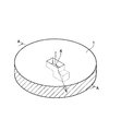
- FIG. 1 is a perspective view schematically showing the overall configuration of an air spinning nozzle (airflow spinning nozzle) 20 according to an embodiment of the present invention.
- FIG. 2 is an enlarged perspective view showing the gas flow path 4 formed in the substrate 1 in detail.
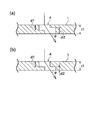
- 3A is a cross-sectional view taken along the line AA in FIG. 2, and
- FIG. 3B is a cross-sectional view showing a modification of the shape of the gas flow path 4.
- a pneumatic spinning nozzle 20 shown in FIG. 1 is for spinning fine fibers 5 and includes a substrate 1 and a cylindrical body 10.
- the substrate 1 is formed in a flat plate shape using silicon as a raw material.
- a plurality of (four) through holes 3 for passing fine fibers 5 and a plurality (four) for ejecting a swirling air flow are formed on the substrate 1.
- the gas flow path 4 is formed.
- the cylindrical body 10 is formed in a cylindrical shape, and one end thereof is bonded to the substrate 1.
- a spinning chamber 11 having a circular cross section is formed inside the cylindrical body 10, and the gas flow path 4 ejects air along the tangential direction of the spinning chamber 11, and a swirling air flow flows into the spinning chamber 11. Can be formed.
- the air flow ejected into the spinning chamber 11 through the gas flow path 4 is inclined with respect to the axial direction of the spinning chamber 11 (the thickness direction of the substrate 1), the swirling air flow in the spinning chamber 11 becomes spiral. With this configuration, the fine fiber 5 is introduced into the spinning chamber 11 from the passage hole 3 in a fiber bundle state, and is twisted by receiving the action of a swirling air flow to be a spun yarn.
- one of the four gas flow paths 4 is shown enlarged.
- this gas flow path 4 rectangular concave portions (first hole and second hole) are formed at different positions from both sides in the thickness direction of the substrate 1, and both concave portions are communicated with each other. It is configured in shape.
- air is injected into the spinning chamber 11 while being bent so as to be slightly inclined from the thickness direction of the substrate 1, as indicated by an arrow in FIG. 2. As a result, a spiral swirl air flow can be formed in the spinning chamber 11 as described above.
- 3A and 3B show a processing example of the shape of the gas flow path 4 as a cross-sectional view taken along the line AA in FIG.
- the value obtained by adding the depth d1 of the recess formed on one surface of the substrate 1 and the depth d2 of the recess formed on the other surface is the thickness of the substrate 1. It is larger than t1 (d1 + d2> t1).
- the gas flow path 4 is formed by a silicon process based on a semiconductor processing technique that is one of the MEMS techniques. Specifically, reactive ions are generated by an inductively coupled plasma processing apparatus (ICP apparatus). Etching is used.
- ICP apparatus inductively coupled plasma processing apparatus
- a metal mask made of chromium for example, is coated on the surface of the substrate 1 made of silicon, and this metal mask is coated with a photoresist or the like.
- a photoresist or the like By selectively etching while masking, an opening corresponding to the opening contour of the gas flow path 4 is formed in the metal mask.
- the substrate 1 is set in an ICP apparatus, and a dry etching process in which a gas containing F atoms is flown and a protective film deposition process in which a fluorocarbon-based gas is flown are alternately repeated to cope with the opening of the metal mask.
- a recess having a predetermined depth and having a predetermined depth can be half-etched.
- the second substrate 2 in which the through hole 7 is formed is fixed in close contact with the substrate 1, and the through hole 7 is arranged offset from the opening of the gas flow path 4, the positional deviation is caused.
- a flow path layout that reduces the jet angle ⁇ at the time of injection is also possible. If the jet angle ⁇ is reduced, a strong whirling airflow can be generated in the spinning chamber 11, so that the fine fibers 5 can be efficiently twisted.
- the second substrate 2 can be a substrate made of, for example, silicoborate glass. Further, as a technique for bonding the second substrate 2 to the silicon substrate 1, for example, a known anodic bonding can be employed.
- each gas flow path 4 is configured as shown in FIG.
- the opening shape of the front surface and the back surface of the substrate 1 is a square of 1 mm
- the positional displacement amount of the opening portions of the front surface and the back surface is 500 ⁇ m
- the direction of the positional displacement is described later.
- the tangential direction of the spinning chamber 11 was set.
- a pipe (not shown) was attached to one surface (the upper surface in FIG. 1) of the substrate 1 and a compressed gas source was connected.
- a simple compressed nitrogen gas was used as the compressed gas source.
- 1 was an acrylic pipe having an inner diameter of 6 mm, and the opening on the downstream side of the gas flow path 4 was disposed so as to face the spinning chamber 11 formed inside the acrylic pipe.
- the second substrate 2 was formed of silicoborate glass and bonded to the substrate 1 by anodic bonding.
- the through hole formed in the second substrate 2 has a diameter of 1 mm.
- the air spinning nozzle 20 in which the gas flow path 4 is formed using the MEMS technology (specifically, reactive ion etching using an ICP apparatus) generates a swirling air flow in the spinning chamber 11 to generate fine fibers.
- MEMS technology specifically, reactive ion etching using an ICP apparatus
- the pneumatic spinning nozzle 20 of the present embodiment is configured to allow a swirling air flow to act on the fine fibers 5.
- the pneumatic spinning nozzle 20 is manufactured by MEMS technology.
- the air spinning nozzle 20 of the present embodiment has a substrate 1 on which a gas flow path 4 for ejecting a swirling air flow is formed.
- the gas flow path 4 includes a concave portion on one surface in the thickness direction of the substrate 1 and a concave portion on the other surface, and is formed as a stepped hole in which the flow channel is inclined from the thickness direction of the substrate 1 as a whole. ing.
- a gas flow path inclined from the thickness direction of the substrate 1 can be formed, and a swirling air flow can be appropriately generated in the spinning chamber 11.
- the flow path cross-sectional area of the gas flow path 4 can be secured, and the swirling air flow can be smoothly ejected to the spinning chamber 11 side.
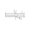
- the pneumatic spinning nozzle 20 having the configuration shown in FIG. 4 includes a second substrate 2 bonded to a surface on one side in the thickness direction of the substrate 1.
- a through hole 7 is formed in the second substrate 2, and the through hole 7 is connected to the gas flow path 4 while forming a step.
- the jet angle ⁇ which is the angle of the air flow ejected from the gas flow path 4 to the spinning chamber 11, can be further reduced.
- a strong swirling air flow can be formed to efficiently twist the fine fiber 5.
- the four gas flow paths 4 are formed in the embodiment of FIG. 1, but can be changed to a configuration having two, three, or five or more gas flow paths.
- the gas flow path 4 is preferably provided at a position that is symmetric with respect to the center of the swirling air flow.
- the second is formed with recesses on the front surface and the back surface of the substrate 1 so that the positions of the gas flow paths 4 are different only in the direction along one side of the rectangle which is the outline of the recess.
- the position is changed in both directions of the two sides of the rectangular shape of the concave portion so that the concave portion is formed on the front surface and the back surface of the substrate 1. can do.
- this arrangement having a two-dimensional deviation, it is possible to set the ejection direction with respect to the supply side of the airflow with a high degree of freedom.
- the contour shape of the recesses it is not necessary for the contour shape of the recesses to be the same on the front surface and the back surface.
- a recess located on the downstream side of the flow channel can be formed in a triangular shape as in the gas flow channel 4b of FIG.
- the direction of the airflow converges toward the tapered shape of the triangle.
- the shape of the gas flow path 4 formed in the substrate 1 can be variously changed.
- the second substrate 2 can be changed so as to be bonded to both surfaces without being configured to bond only to one surface of the substrate 1.
- a so-called three-stage stepped gas channel is formed, and the direction of the swirling airflow can be further stabilized.
- the gas flow path 4 of the pneumatic spinning nozzle 20 is not limited to the case where it is formed by reactive ion etching using an ICP apparatus.
- a gas flow path having the same configuration as that of the above-described embodiment can be formed by known ultraviolet lithography using a thick film resist.
- the air spinning nozzle 20 can be changed to be formed by a selective growth process regardless of the etching process.
- an appropriate gas such as the above-described nitrogen may be supplied to the gas flow path 4 to change to a structure in which airflow spinning is performed. it can.
Landscapes
- Engineering & Computer Science (AREA)
- Mechanical Engineering (AREA)
- Textile Engineering (AREA)
- Spinning Methods And Devices For Manufacturing Artificial Fibers (AREA)
- Spinning Or Twisting Of Yarns (AREA)
Abstract
旋回気流を安定的に生成して微細繊維を気流紡績できる安価な気流紡績ノズルを提供する。空気紡績ノズル20は、微細繊維5に旋回空気流を作用させるためのものであって、MEMS技術によって製造されている。この空気紡績ノズル20は、旋回空気流を噴出させるためのガス流路4が形成された基板1を有する。ガス流路4は、基板1の厚み方向一側の面の凹部と、他側の面の凹部とからなり、全体として基板1の厚み方向から流路が傾斜する段付き孔として形成されている。
Description
本発明は、主要には、微細繊維を旋回気流で紡績するための気流紡績ノズルに関する。
従来から、ドラフト装置によりドラフトされた繊維束に、旋回空気流を作用させて加撚することにより紡績糸を製造する空気紡績装置が知られている。このような紡績装置においては、例えば特許文献1及び2に示すように、旋回気流を発生させるための空気紡績ノズルが使用されている。
近年、微細な繊維であるマイクロファイバー及びナノファイバーがその機能性等の点で注目されており、従来よりも連続生産性が高く、高品質かつ高付加価値な微細繊維を生成するニーズが高まっている。しかしながら、このような微細繊維の紡績糸径は10μm以下であるので、例えば綿(紡績糸径が0.1mm程度以上)を対象とする特許文献1及び2のような空気紡績ノズルをそのまま使用することはできなかった。
また、特許文献1及び2の空気紡績ノズルを寸法的に縮小したノズルを設計する場合、従来の機械加工技術では精度、コスト及び量産性の点で課題が多かった。特に、斜め方向に空気を噴出して旋回気流を形成するためのノズル孔を高精度に加工することが困難であり、安定した旋回気流で微細繊維を紡績する観点から改善の余地が残されていた。
本発明は以上の事情に鑑みてされたものであり、その目的は、旋回気流を安定的に生成して微細繊維を気流紡績できる安価な気流紡績ノズルを提供することにある。
本発明の解決しようとする課題は以上の如くであり、次にこの課題を解決するための手段とその効果を説明する。
本発明の第1の観点によれば、微細繊維に旋回気流を作用させるための気流紡績ノズルであって、MEMS技術によって製造される気流紡績ノズルが提供される。
これにより、MEMSによる高精度の微細加工を利用することで、旋回気流を安定的に生成して微細繊維を気流紡績できる気流紡績ノズルを提供することができる。
前記の気流紡績ノズルにおいては、以下の構成とすることが好ましい。即ち、この気流紡績ノズルは、前記旋回気流を噴出させるためのガス流路が形成された基板を有する。前記ガス流路は、前記基板の厚み方向一側の面の第1穴と、他側の面の第2穴とからなり、全体として前記基板の厚み方向から流路が傾斜する段付き孔として形成されている。
これにより、直線的な斜め方向のガス流路を形成せずとも、基板の厚み方向のエッチング加工を組み合わせて、当該基板の厚み方向から傾斜したガス流路を高い寸法精度で形成することができる。従って、簡単な加工で、紡績室内に旋回気流を適切に生成することができる。
前記の気流紡績ノズルにおいては、前記第1穴の深さと、前記第2穴の深さと、を加算した値が、前記基板の厚みを上回っていることが好ましい。
これにより、ガス流路の流路断面積を確保し、旋回気流を紡績室側へ円滑に噴出させることができる。
前記の気流紡績ノズルにおいては、以下の構成とすることが好ましい。即ち、この気流紡績ノズルは、前記基板の厚み方向で少なくとも一側の面に接合される第2基板を備える。前記第2基板には貫通孔が形成され、前記貫通孔は、段差を形成しながら前記ガス流路に対して接続している。
これにより、ガス流路から紡績室へ噴出される気流の向きを基板の厚み方向から一層傾斜させることができる。従って、強い旋回気流を形成して微細繊維に撚りを効率的に掛けることができる。
本発明の第2の観点によれば、微細繊維用気流紡績ノズルの製造方法であって、MEMS技術を用いる工程を含む微細繊維用気流紡績ノズルの製造方法が提供される。
これにより、MEMSによる高精度の微細加工を利用することで、旋回気流を安定的に生成して微細繊維を気流紡績できる気流紡績ノズルを提供できる。
前記の微細繊維用気流紡績ノズルの製造方法においては、基板の厚み方向両側からハーフエッチングを行って、全体として前記基板の厚み方向から傾斜している段付き孔からなるガス流路を形成する工程を含むことが好ましい。
これにより、基板の厚み方向のエッチング加工を組み合わせて、当該基板の厚み方向から傾斜したガス流路を高い寸法精度で形成し、紡績室内に旋回気流を適切に生成することができる。
次に、図面を参照して本発明の実施の形態を説明する。図1は、本発明の一実施形態に係る空気紡績ノズル(気流紡績ノズル)20の全体的な構成を模式的に示す斜視図である。図2は、基板1に形成されたガス流路4を詳細に示す拡大斜視図である。図3(a)は図2のA-A断面矢視図であり、図3(b)はガス流路4の形状の変形例を示す断面図である。
図1に示す空気紡績ノズル20は微細繊維5を紡績するためのものであり、基板1と、筒体10と、を備えている。基板1はシリコンを素材として平板状に形成されており、この基板1には、微細繊維5を通過させるための貫通状の通過孔3と、旋回空気流を噴出させるための複数(4つ)のガス流路4と、が形成されている。
筒体10は円筒状に形成されており、その一端が基板1に接合されている。筒体10の内部には断面円形の紡績室11が形成されており、前記ガス流路4は、この紡績室11の接線方向に沿って空気を噴出し、紡績室11の内部に旋回空気流を形成することができる。ただし、ガス流路4を通過して紡績室11に噴出される空気流は紡績室11の軸線方向(基板1の厚み方向)に対して傾斜しているので、紡績室11内の旋回空気流は螺旋状となる。この構成で、微細繊維5は、通過孔3から紡績室11に繊維束状態で導入され、旋回空気流の作用を受けることで撚られて紡績糸とされる。
図2には、4つのガス流路4のうち1つが拡大して示されている。このガス流路4は、基板1の厚み方向両側の面から矩形状の凹部(第1穴及び第2穴)を互いに位置を異ならせてそれぞれ形成し、両方の凹部を相互に連絡したような形状に構成されている。この段付き孔状のガス流路4により、空気は図2の矢印で示すように、基板1の厚み方向から若干傾斜するように曲げられながら紡績室11へ噴射される。この結果、前述のように螺旋
状の旋回空気流を紡績室11内に形成することができる。
状の旋回空気流を紡績室11内に形成することができる。
図3(a)及び図3(b)には、ガス流路4の形状の加工例が図2のA-A断面矢視図として示されている。図3(a)の例では、基板1の一側の面に形成した凹部の深さd1と、他側の面に形成した凹部の深さd2と、を加算した値が、基板1の厚みt1より大きくなっている(d1+d2>t1)。このように両側の凹部が基板の厚み方向にオーバーラップするように形成されることで、ガス流路4内に形成される段差の位置を基板の厚み方向で異ならせることができる。この結果、ガス流路4の流路断面積を確保できるので、空気はガス流路4を円滑に通過して紡績室11側に噴射される。
本実施形態において前記ガス流路4は、MEMS技術の手法の1つである半導体加工技術によるシリコンプロセスで形成されており、具体的には、誘導結合プラズマ処理装置(ICP装置)による反応性イオンエッチングが利用されている。
この方法は公知のものであるので詳細は省略するが、概略を以下に示すと、最初に、シリコンからなる基板1の表面に例えばクロムからなる金属マスクを被覆し、この金属マスクをフォトレジスト等でマスクしながら選択的にエッチングすることで、前記ガス流路4の開口輪郭に相当する開口を当該金属マスクに形成する。そして、この基板1をICP装置にセットし、F原子を含むガスを流すドライエッチング工程と、フルオロカーボン系のガスを流す保護膜堆積工程と、を交互に繰り返すことで、前記金属マスクの開口に対応する輪郭を有する所定の深さの凹部をハーフエッチング加工することができる。
なお、上記の基板1の表裏面からのハーフエッチングでは、表裏の凹部の位置を異ならせることで、図3(a)又は図3(b)のように1段の位置ズレを実現できるにとどまる。一方、図4に示すように、貫通孔7を形成した第2基板2を基板1に対し密着させて固定し、前記貫通孔7をガス流路4の開口からオフセットして配置すると、位置ズレが2段となり、噴射時における噴流角度θを小さくするような流路レイアウトも可能になる。噴流角度θを小さくすると紡績室11内に強い旋回気流を発生させることができるので、微細繊維5に撚りを効率的に掛けることができる。この第2基板2は、例えば珪ホウ酸ガラスからなる基板とすることができる。また、この第2基板2をシリコンの基板1に結合させる手法としては、例えば公知の陽極接合を採用することができる。
次に、本実施形態の方法で製造した空気紡績ノズル20を用いた検証実験について説明する。先ず、シリコンからなる基板1に、図1に示すように4つの段差孔状のガス流路4を形成し、空気紡績ノズル20を作製した。それぞれのガス流路4は、図3(a)に示すような構成とした。それぞれのガス流路4の具体的な寸法としては、基板1の表面及び裏面の開口形状は何れも1mmの正方形とし、表面及び裏面の開口部の位置ズレ量は500μm、位置ズレの方向は後述の紡績室11の接線方向とした。
そして、基板1の一側の面(図1において上側の面)に図略の配管を取り付け、圧縮ガス源を接続した。今回の実験では、圧縮ガス源として、簡便な圧縮窒素ガスを採用した。また、図1に示す筒体10は内径6mmのアクリルパイプとし、ガス流路4の下流側の開口を、アクリルパイプの内側に形成された紡績室11に臨ませるように配置した。
そして、紡績室11にネジレの無い繊維束を挿入し、4つのガス流路4に均等に窒素ガスを供給して、旋回気流によって繊維を捻る実験を行った。繊維としては、太さが1束約350μmの綿繊維と、約30μmの化学繊維の2種類を実験に用いた。圧縮窒素ガスをガス流路4から噴射させて目視で観察したところ、2種類の繊維は何れも、空気紡績ノズル20によってネジリが生じていることが確認された。
次に、図4の構成に示すような流路構造を有する空気紡績ノズルについて検証した。第2基板2は珪ホウ酸ガラスで形成するとともに、基板1に対して陽極接合によって接合した。また、第2基板2に形成された貫通孔は直径1mmとした。その他の条件については上記と同様として再び実験したところ、図3(a)よりも図4の構成の方がより強い旋回気流が得られ、繊維のネジリが一層強くなっていることが確かめられた。
以上のように、MEMS技術(具体的には、ICP装置による反応性イオンエッチング)を用いてガス流路4を形成した空気紡績ノズル20は、紡績室11に旋回空気流を発生させて微細繊維5を空気紡績するデバイスとして有効に機能するとの知見が得られた。
以上に説明したように、本実施形態の空気紡績ノズル20は、微細繊維5に旋回空気流を作用させることができるように構成されている。また、この空気紡績ノズル20は、MEMS技術によって製造されている。
これにより、MEMSによる高精度の微細加工を利用することで、旋回気流を安定的に生成して微細繊維5を空気紡績できる空気紡績ノズル20を提供することができる。
また、本実施形態の空気紡績ノズル20は、旋回空気流を噴出させるためのガス流路4が形成された基板1を有する。ガス流路4は、基板1の厚み方向一側の面の凹部と、他側の面の凹部とからなり、全体として基板1の厚み方向から流路が傾斜するような段付き孔として形成されている。
これにより、基板1の厚み方向のエッチング加工を組み合わせて、当該基板1の厚み方向から傾斜したガス流路を形成し、紡績室11内に旋回空気流を適切に生成することができる。
また、本実施形態の空気紡績ノズル20においては、図3(a)に示すように、基板1の厚み方向一側の面からのハーフエッチングの深さ(凹部の深さ)d1と、他側の面からのハーフエッチングの深さ(凹部の深さ)d2と、を加算した値が、基板1の厚みt1を上回っている。
これにより、ガス流路4の流路断面積を確保し、旋回空気流を紡績室11側へ円滑に噴出させることができる。
また、図4に示す構成の空気紡績ノズル20は、基板1の厚み方向一側の面に接合される第2基板2を備える。第2基板2には貫通孔7が形成され、この貫通孔7は、段差を形成しながらガス流路4に対して接続している。
これにより、2段の段付き孔状のガス流路が全体として形成されるので、ガス流路4から紡績室11へ噴出される気流の角度である噴流角度θを一層小さくすることができ、強い旋回空気流を形成して微細繊維5に撚りを効率的に掛けることができる。
以上に本発明の好適な実施の形態を説明したが、上記の構成は例えば以下のように変更することができる。
ガス流路4は、図1の実施形態では4つ形成されているが、2つ、3つ、又は5つ以上のガス流路を有する構成に変更することができる。なお、ガス流路4は、旋回空気流の中心に関して対称となる位置に設けるのが良い。
図2に示すガス流路4は、凹部の輪郭である矩形の1辺に沿う方向にのみ位置を異ならせるようにして、基板1の表面と裏面の凹部が形成されている。しかしながら、これに代えて、例えば図5のガス流路4aのように、凹部の矩形の2辺の方向に何れも位置を異ならせて、基板1の表面と裏面に凹部を形成するように変更することができる。この2次元的なズレを有する配置により、気流の供給側に対する噴出方向を高い自由度で設定することが可能になる。また、表面と裏面で凹部の輪郭形状が一致している必要はなく、例えば図6のガス流路4bのように、流路の下流側に位置する凹部を三角形に形成することができる。この例では、気流の向きが三角形の先細部に向かって収束することが期待できる。以上に例示するように、基板1に形成するガス流路4の形状は様々に変更することができる。
第2基板2は、基板1の一側の面にのみ接合する構成とせず、両側の面に接合するように変更することができる。この場合、いわゆる3段の段付き孔状のガス流路が形成され、旋回気流の向きをより安定化させることができる。
前記空気紡績ノズル20のガス流路4は、ICP装置による反応性イオンエッチングによって形成する場合に限定されない。例えば、厚膜レジストを用いた公知の紫外線リソグラフィによっても、前記実施形態と同様の構成のガス流路を形成することができる。あるいは、エッチングプロセスによらず、選択成長プロセスによって空気紡績ノズル20を形成するように変更することができる。
ガス流路4に圧縮空気が供給される構成の前記空気紡績ノズル20に代えて、例えば上記の窒素のような適宜のガスをガス流路4に供給して気流紡績する構成に変更することができる。
Claims (6)
- 微細繊維に旋回気流を作用させるための気流紡績ノズルであって、MEMS技術によって製造されていることを特徴とする気流紡績ノズル。
- 請求項1に記載の気流紡績ノズルであって、
前記旋回気流を噴出させるためのガス流路が形成された基板を有し、
前記ガス流路は、前記基板の厚み方向一側の面の第1穴と、他側の面の第2穴とからなり、全体として前記基板の厚み方向から流路が傾斜する段付き孔として形成されていることを特徴とする気流紡績ノズル。 - 請求項2に記載の気流紡績ノズルであって、
前記第1穴の深さと、前記第2穴の深さと、を加算した値が、前記基板の厚みを上回っていることを特徴とする気流紡績ノズル。 - 請求項2又は3に記載の気流紡績ノズルであって、
前記基板の厚み方向で少なくとも一側の面に接合される第2基板を備え、
前記第2基板には貫通孔が形成され、前記貫通孔は、段差を形成しながら前記ガス流路に対して接続していることを特徴とする気流紡績ノズル。 - 微細繊維用気流紡績ノズルの製造方法であって、MEMS技術を用いる工程を含むことを特徴とする微細繊維用気流紡績ノズルの製造方法。
- 請求項5に記載の微細繊維用気流紡績ノズルの製造方法であって、
基板の厚み方向両側からハーフエッチングを行って、全体として前記基板の厚み方向から傾斜している段付き孔からなるガス流路を形成する工程を含むことを特徴とする微細繊維用気流紡績ノズルの製造方法。
Applications Claiming Priority (2)
| Application Number | Priority Date | Filing Date | Title |
|---|---|---|---|
| JP2009033869A JP2010189790A (ja) | 2009-02-17 | 2009-02-17 | 気流紡績ノズル及び微細繊維用気流紡績ノズルの製造方法 |
| JP2009-033869 | 2009-02-17 |
Publications (1)
| Publication Number | Publication Date |
|---|---|
| WO2010095489A1 true WO2010095489A1 (ja) | 2010-08-26 |
Family
ID=42633775
Family Applications (1)
| Application Number | Title | Priority Date | Filing Date |
|---|---|---|---|
| PCT/JP2010/050870 Ceased WO2010095489A1 (ja) | 2009-02-17 | 2010-01-25 | 気流紡績ノズル及び微細繊維用気流紡績ノズルの製造方法 |
Country Status (2)
| Country | Link |
|---|---|
| JP (1) | JP2010189790A (ja) |
| WO (1) | WO2010095489A1 (ja) |
Families Citing this family (1)
| Publication number | Priority date | Publication date | Assignee | Title |
|---|---|---|---|---|
| JP5716320B2 (ja) | 2010-08-26 | 2015-05-13 | 市光工業株式会社 | 車両用前照灯および車両用前照灯装置 |
Citations (4)
| Publication number | Priority date | Publication date | Assignee | Title |
|---|---|---|---|---|
| JPH07133536A (ja) * | 1993-11-09 | 1995-05-23 | Murata Mach Ltd | マイクロファイバーを用いた紡績糸の製造方法 |
| JP3546761B2 (ja) * | 1999-06-03 | 2004-07-28 | 村田機械株式会社 | 紡績ノズル |
| US6770208B1 (en) * | 2001-03-21 | 2004-08-03 | The United States Of America As Represented By The Administrator Of The National Aeronautics And Space Administration | Method for forming MEMS-based spinning nozzle |
| JP3551872B2 (ja) * | 1999-11-30 | 2004-08-11 | 村田機械株式会社 | 紡績装置 |
-
2009
- 2009-02-17 JP JP2009033869A patent/JP2010189790A/ja active Pending
-
2010
- 2010-01-25 WO PCT/JP2010/050870 patent/WO2010095489A1/ja not_active Ceased
Patent Citations (4)
| Publication number | Priority date | Publication date | Assignee | Title |
|---|---|---|---|---|
| JPH07133536A (ja) * | 1993-11-09 | 1995-05-23 | Murata Mach Ltd | マイクロファイバーを用いた紡績糸の製造方法 |
| JP3546761B2 (ja) * | 1999-06-03 | 2004-07-28 | 村田機械株式会社 | 紡績ノズル |
| JP3551872B2 (ja) * | 1999-11-30 | 2004-08-11 | 村田機械株式会社 | 紡績装置 |
| US6770208B1 (en) * | 2001-03-21 | 2004-08-03 | The United States Of America As Represented By The Administrator Of The National Aeronautics And Space Administration | Method for forming MEMS-based spinning nozzle |
Non-Patent Citations (1)
| Title |
|---|
| YOHEI TADA ET AL.: "Senkairyu o Mochiita Kuki Seibo no Tameno Micro Naname Funryu Nozzle no Sakusei to Sono Hyoka", NATIONAL CONVENTION RECORD I.E.E. JAPAN, vol. 2009, no. 3, 17 March 2009 (2009-03-17), pages 176 * |
Also Published As
| Publication number | Publication date |
|---|---|
| JP2010189790A (ja) | 2010-09-02 |
Similar Documents
| Publication | Publication Date | Title |
|---|---|---|
| JP5502361B2 (ja) | ランダムパターンで接着剤フィラメントを吐出するノズルおよび方法 | |
| JP5162975B2 (ja) | 紡績装置 | |
| RU2149226C1 (ru) | Способ изготовления диска с отверстиями | |
| JP4763575B2 (ja) | 基板処理装置および基板処理方法 | |
| CN100541709C (zh) | 基板处理装置以及基板处理方法 | |
| CN105121025B (zh) | 射流喷嘴和振荡器回路 | |
| JP5296831B2 (ja) | 接着剤塗布ヘッド | |
| CN109311036B (zh) | 微结构喷嘴 | |
| CN102029793A (zh) | 喷墨用的擦拭装置、以及使用该装置的擦拭方法 | |
| JP6361165B2 (ja) | ネブライザおよびネブライザキット | |
| JP4220640B2 (ja) | 海島型複合繊維の紡糸口金及びそれを用いた紡糸方法 | |
| CN104736836A (zh) | 具有改善的燃料排放系数的燃料喷射器 | |
| JP2022507153A (ja) | 紡糸繊維の製造に使用するための一体化された紡糸口金本体及びノズルを有する紡糸口金ブロック | |
| JP2015159991A5 (ja) | ||
| JP6063012B1 (ja) | 極細繊維不織布の製造方法及び製造装置 | |
| KR20070115978A (ko) | 스팟 사의 제조 방법 및 와류 노즐 | |
| WO2010095489A1 (ja) | 気流紡績ノズル及び微細繊維用気流紡績ノズルの製造方法 | |
| CN1434157A (zh) | 影响空气涡流纺纱设备锭子通道中轴向流动的方法 | |
| TW202118724A (zh) | 微流體元件及其製造方法 | |
| CN110290876A (zh) | 双流体喷嘴 | |
| JP2009054755A (ja) | 基板処理装置 | |
| JP2008516099A5 (ja) | ||
| JP5167040B2 (ja) | 穴内面照射用噴射ノズル | |
| KR20060097411A (ko) | 콜드 스프레이용 노즐 및 이를 이용한 콜드 스프레이 장치 | |
| JP2017203233A (ja) | メルトブロー用ダイ |
Legal Events
| Date | Code | Title | Description |
|---|---|---|---|
| 121 | Ep: the epo has been informed by wipo that ep was designated in this application |
Ref document number: 10743618 Country of ref document: EP Kind code of ref document: A1 |
|
| NENP | Non-entry into the national phase |
Ref country code: DE |
|
| 122 | Ep: pct application non-entry in european phase |
Ref document number: 10743618 Country of ref document: EP Kind code of ref document: A1 |