WO2010095248A1 - Générateur entraîné par le vent et son procédé de commande - Google Patents
Générateur entraîné par le vent et son procédé de commande Download PDFInfo
- Publication number
- WO2010095248A1 WO2010095248A1 PCT/JP2009/053079 JP2009053079W WO2010095248A1 WO 2010095248 A1 WO2010095248 A1 WO 2010095248A1 JP 2009053079 W JP2009053079 W JP 2009053079W WO 2010095248 A1 WO2010095248 A1 WO 2010095248A1
- Authority
- WO
- WIPO (PCT)
- Prior art keywords
- generator
- converter
- power
- inverter
- rotational speed
- Prior art date
Links
- 238000000034 method Methods 0.000 title claims description 10
- 230000001360 synchronised effect Effects 0.000 claims abstract description 19
- 238000004804 winding Methods 0.000 claims description 22
- 230000007423 decrease Effects 0.000 description 5
- 230000006698 induction Effects 0.000 description 5
- 238000010586 diagram Methods 0.000 description 4
- 241000219793 Trifolium Species 0.000 description 1
- 230000002238 attenuated effect Effects 0.000 description 1
- 238000007796 conventional method Methods 0.000 description 1
- 230000003247 decreasing effect Effects 0.000 description 1
- 210000003746 feather Anatomy 0.000 description 1
- 230000001172 regenerating effect Effects 0.000 description 1
Images


Classifications
-
- F—MECHANICAL ENGINEERING; LIGHTING; HEATING; WEAPONS; BLASTING
- F03—MACHINES OR ENGINES FOR LIQUIDS; WIND, SPRING, OR WEIGHT MOTORS; PRODUCING MECHANICAL POWER OR A REACTIVE PROPULSIVE THRUST, NOT OTHERWISE PROVIDED FOR
- F03D—WIND MOTORS
- F03D7/00—Controlling wind motors
- F03D7/02—Controlling wind motors the wind motors having rotation axis substantially parallel to the air flow entering the rotor
- F03D7/026—Controlling wind motors the wind motors having rotation axis substantially parallel to the air flow entering the rotor for starting-up
-
- F—MECHANICAL ENGINEERING; LIGHTING; HEATING; WEAPONS; BLASTING
- F03—MACHINES OR ENGINES FOR LIQUIDS; WIND, SPRING, OR WEIGHT MOTORS; PRODUCING MECHANICAL POWER OR A REACTIVE PROPULSIVE THRUST, NOT OTHERWISE PROVIDED FOR
- F03D—WIND MOTORS
- F03D7/00—Controlling wind motors
- F03D7/02—Controlling wind motors the wind motors having rotation axis substantially parallel to the air flow entering the rotor
- F03D7/04—Automatic control; Regulation
-
- F—MECHANICAL ENGINEERING; LIGHTING; HEATING; WEAPONS; BLASTING
- F03—MACHINES OR ENGINES FOR LIQUIDS; WIND, SPRING, OR WEIGHT MOTORS; PRODUCING MECHANICAL POWER OR A REACTIVE PROPULSIVE THRUST, NOT OTHERWISE PROVIDED FOR
- F03D—WIND MOTORS
- F03D7/00—Controlling wind motors
- F03D7/02—Controlling wind motors the wind motors having rotation axis substantially parallel to the air flow entering the rotor
- F03D7/022—Adjusting aerodynamic properties of the blades
- F03D7/0224—Adjusting blade pitch
-
- F—MECHANICAL ENGINEERING; LIGHTING; HEATING; WEAPONS; BLASTING
- F03—MACHINES OR ENGINES FOR LIQUIDS; WIND, SPRING, OR WEIGHT MOTORS; PRODUCING MECHANICAL POWER OR A REACTIVE PROPULSIVE THRUST, NOT OTHERWISE PROVIDED FOR
- F03D—WIND MOTORS
- F03D7/00—Controlling wind motors
- F03D7/02—Controlling wind motors the wind motors having rotation axis substantially parallel to the air flow entering the rotor
- F03D7/0276—Controlling wind motors the wind motors having rotation axis substantially parallel to the air flow entering the rotor controlling rotor speed, e.g. variable speed
-
- H—ELECTRICITY
- H02—GENERATION; CONVERSION OR DISTRIBUTION OF ELECTRIC POWER
- H02P—CONTROL OR REGULATION OF ELECTRIC MOTORS, ELECTRIC GENERATORS OR DYNAMO-ELECTRIC CONVERTERS; CONTROLLING TRANSFORMERS, REACTORS OR CHOKE COILS
- H02P9/00—Arrangements for controlling electric generators for the purpose of obtaining a desired output
-
- F—MECHANICAL ENGINEERING; LIGHTING; HEATING; WEAPONS; BLASTING
- F05—INDEXING SCHEMES RELATING TO ENGINES OR PUMPS IN VARIOUS SUBCLASSES OF CLASSES F01-F04
- F05B—INDEXING SCHEME RELATING TO WIND, SPRING, WEIGHT, INERTIA OR LIKE MOTORS, TO MACHINES OR ENGINES FOR LIQUIDS COVERED BY SUBCLASSES F03B, F03D AND F03G
- F05B2220/00—Application
- F05B2220/70—Application in combination with
- F05B2220/706—Application in combination with an electrical generator
- F05B2220/7064—Application in combination with an electrical generator of the alternating current (A.C.) type
- F05B2220/70644—Application in combination with an electrical generator of the alternating current (A.C.) type of the asynchronous type, i.e. induction type
-
- F—MECHANICAL ENGINEERING; LIGHTING; HEATING; WEAPONS; BLASTING
- F05—INDEXING SCHEMES RELATING TO ENGINES OR PUMPS IN VARIOUS SUBCLASSES OF CLASSES F01-F04
- F05B—INDEXING SCHEME RELATING TO WIND, SPRING, WEIGHT, INERTIA OR LIKE MOTORS, TO MACHINES OR ENGINES FOR LIQUIDS COVERED BY SUBCLASSES F03B, F03D AND F03G
- F05B2270/00—Control
- F05B2270/10—Purpose of the control system
- F05B2270/107—Purpose of the control system to cope with emergencies
-
- F—MECHANICAL ENGINEERING; LIGHTING; HEATING; WEAPONS; BLASTING
- F05—INDEXING SCHEMES RELATING TO ENGINES OR PUMPS IN VARIOUS SUBCLASSES OF CLASSES F01-F04
- F05B—INDEXING SCHEME RELATING TO WIND, SPRING, WEIGHT, INERTIA OR LIKE MOTORS, TO MACHINES OR ENGINES FOR LIQUIDS COVERED BY SUBCLASSES F03B, F03D AND F03G
- F05B2270/00—Control
- F05B2270/30—Control parameters, e.g. input parameters
- F05B2270/327—Rotor or generator speeds
-
- F—MECHANICAL ENGINEERING; LIGHTING; HEATING; WEAPONS; BLASTING
- F05—INDEXING SCHEMES RELATING TO ENGINES OR PUMPS IN VARIOUS SUBCLASSES OF CLASSES F01-F04
- F05B—INDEXING SCHEME RELATING TO WIND, SPRING, WEIGHT, INERTIA OR LIKE MOTORS, TO MACHINES OR ENGINES FOR LIQUIDS COVERED BY SUBCLASSES F03B, F03D AND F03G
- F05B2270/00—Control
- F05B2270/30—Control parameters, e.g. input parameters
- F05B2270/328—Blade pitch angle
-
- Y—GENERAL TAGGING OF NEW TECHNOLOGICAL DEVELOPMENTS; GENERAL TAGGING OF CROSS-SECTIONAL TECHNOLOGIES SPANNING OVER SEVERAL SECTIONS OF THE IPC; TECHNICAL SUBJECTS COVERED BY FORMER USPC CROSS-REFERENCE ART COLLECTIONS [XRACs] AND DIGESTS
- Y02—TECHNOLOGIES OR APPLICATIONS FOR MITIGATION OR ADAPTATION AGAINST CLIMATE CHANGE
- Y02E—REDUCTION OF GREENHOUSE GAS [GHG] EMISSIONS, RELATED TO ENERGY GENERATION, TRANSMISSION OR DISTRIBUTION
- Y02E10/00—Energy generation through renewable energy sources
- Y02E10/70—Wind energy
- Y02E10/72—Wind turbines with rotation axis in wind direction
Definitions
- the present invention relates to a wind turbine generator and a control method thereof.
- control called feathering that moves the pitch angle of the windmill blade to the feather side is generally performed.
- FIG. 4 shows the relationship between torque and current with respect to the slip of the induction machine. As shown in FIG. 4, it can be seen that both the torque and the current increase as the slip increases.
- the slip is a parameter represented by the following equation (1).
- the induction machine When the slip is greater than zero, the induction machine acts as an electric motor, and when the slip is less than zero, the induction machine motor acts as a generator (regenerative operation).
- An object of the present invention is to provide a wind turbine generator capable of suppressing an increase in torque when the system voltage is recovered and reducing a load on the equipment due to the torque, and a control method thereof.
- a first aspect of the present invention includes a generator, a converter that converts the output of the generator rotor from three-phase AC power to DC power, and an inverter that converts DC power output from the converter into three-phase AC power
- a power control unit that controls the converter and the inverter, the power control unit is configured to operate the converter and the inverter based on a rotor current of the generator or a DC voltage converted by the converter.
- a wind power generator that controls stop / restart, and includes a blade control unit that controls a pitch angle of a wind turbine blade. The blade control unit is configured to stop the operation of the converter and the inverter by the power control unit.
- the pitch angle of the wind turbine blade is controlled so that the rotational speed of the generator is equal to or higher than the synchronous rotational speed.
- the power control unit matches a target pitch angle determined based on at least one of wind speed, the rotational speed of the generator, and a required output.
- it is a wind power generator which controls the pitch angle of a windmill blade.
- the operation of the converter and the inverter is determined to stop depending on the rotor current of the generator or the state of the DC voltage converted by the converter, regardless of the state of the power system.
- This control is a control generally performed conventionally. Therefore, it is not necessary to provide a new sensor or the like for detecting whether or not the system voltage has decreased, and it is possible to detect a decrease in system voltage or the like using conventional techniques.
- the blade control unit controls the pitch angle of the wind turbine blades so that the rotational speed of the generator becomes equal to or higher than the synchronous rotational speed. It recovers and it becomes possible to prevent the generation of a large torque or the generation of the anti-load torque when the control of the converter and the inverter is resumed. Thereby, the load to the apparatus by a torque can be reduced.
- the wind turbine generator is connected to the rotor winding of the generator, and when the current flowing through the rotor winding is equal to or higher than a predetermined current threshold or the DC voltage converted by the converter is equal to or higher than a predetermined voltage threshold.
- the blade control unit has a crowbar circuit that is activated when the rotor winding is short-circuited, and the blade control unit operates the crowbar circuit, and the power control unit stops the operation of the converter and the inverter.
- the pitch angle of the wind turbine blade is controlled so that the rotational speed of the generator is equal to or higher than the synchronous rotational speed or the synchronous rotational speed, the crowbar circuit is deactivated, and the power control unit When the operation of the converter and the inverter is resumed, it is determined based on at least one of the wind speed, the rotational speed of the generator, and the required output. To match the target pitch angle that is, it is also possible to control the pitch angle of the wind turbine blade.
- the pitch angle control of the wind turbine blades may be switched in consideration of the operation state of the crowbar circuit in addition to the operation state of the converter and the inverter.
- a second aspect of the present invention is a generator, a converter that converts the output of the generator rotor from three-phase AC power to DC power, and an inverter that converts DC power output from the converter into three-phase AC power
- a power control unit that controls the converter and the inverter, the power control unit is configured to operate the converter and the inverter based on a rotor current of the generator or a DC voltage converted by the converter.
- a method for controlling a wind turbine generator for controlling stop / restart wherein when the operation of the converter and the inverter is stopped by the power control unit, the rotational speed of the generator is a synchronous rotational speed or a synchronous rotational speed.
- the pitch angle of the wind turbine blade is controlled, and the converter and the inverter are controlled by the power control unit.
- the wind power for controlling the pitch angle of the wind turbine blade so as to coincide with a target pitch angle determined based on at least one of the wind speed, the rotational speed of the generator, and the required output It is a control method of a power generator.
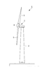
- FIG. 1 is a block diagram showing the overall configuration of the wind turbine generator according to the present embodiment.
- the wind turbine generator 1 includes a support column 2, a nacelle 3 installed at the upper end of the support column 2, and a rotor head 4 provided in the nacelle 3 so as to be rotatable around a substantially horizontal axis.
- a rotor head 4 provided in the nacelle 3 so as to be rotatable around a substantially horizontal axis.
- Three wind turbine blades 5 are attached to the rotor head 4 radially around the rotation axis thereof.
- the force of the wind striking the wind turbine blade 5 from the direction of the rotation axis of the rotor head 4 is converted into power for rotating the rotor head 4 around the rotation axis, and this power is generated by the generator housed in the nacelle 3. It is converted to electrical energy.
- the nacelle 3 is provided with a wind speed anemometer (not shown). An anemometer measures a wind speed and a wind direction. The nacelle 3 is turned in response to the wind speed and the wind direction measured by the anemometer.
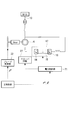
- FIG. 2 is a block diagram showing an example of the configuration of the generator 6 and its surroundings.
- the generator (induction machine) 6 is configured such that the electric power generated by the generator 6 can be output from both the stator winding and the rotor winding to the power system 13.
- the generator 6 has a stator winding connected to the power system 13 and a rotor winding connected to the power system 13 via an AC-DC-AC converter 17.
- the AC-DC-AC converter 17 includes a converter 14, a DC bus 15, and an inverter 16, and converts AC power received from the rotor windings into AC power suitable for the frequency of the power system 13.
- Converter 14 converts AC power generated in the rotor windings into DC power and outputs the DC power to DC bus 15.
- the inverter 16 converts the DC power received from the DC bus 15 into AC power having the same frequency as that of the power system 13 and outputs the AC power.
- the AC-DC-AC converter 17 also has a function of converting the AC power received from the power system 13 into AC power adapted to the frequency of the rotor winding.
- the inverter 16 converts AC power into DC power and outputs the DC power to the DC bus 15.
- the converter 14 converts the DC power received from the DC bus 15 into AC power suitable for the frequency of the rotor winding, and supplies the AC power to the rotor winding of the generator 5.
- a crowbar circuit 27 for overcurrent protection of the converter 14 is connected to the rotor winding.
- the crowbar circuit 27 is activated when the current flowing through the rotor winding or the voltage of the DC bus 15 exceeds a predetermined threshold value, and shorts the rotor winding through a resistor.
- the current of the rotor winding is attenuated so that no overcurrent flows to the converter 14.
- it is good also as making it short-circuit directly, without going through resistance.
- a voltage / current sensor (not shown) for measuring the output voltage V and the output current I of the generator 5 is provided on the power line connecting the generator 5 to the power system 13. The measured value of the voltage / current sensor is given to the power control unit 21.
- the power control unit 21 controls on / off of the power transistor of the converter 14 in order to control the active power P and the reactive power Q output in response to the active power command P * and the reactive power command Q * .
- the power control unit 21 calculates active power P and reactive power Q from the output voltage V and the output current I measured by the voltage / current sensor. Further, the power control unit 21 generates a PWM signal such that the difference between the active power P and the active power command P * and the difference between the reactive power Q and the reactive power command Q * are zero, and the generated PWM signal Is supplied to the converter 14. Thereby, the active power P and the reactive power Q are controlled.
- the power control unit 21 monitors the generator rotor current and the DC link voltage. When these values exceed a preset current threshold value and voltage threshold value, the power control unit 21 activates the crowbar circuit 27 and the converter 14. And switching of the inverter 16 is turned off. This control is generally performed. In this way, the control contents are switched according to the behavior of the generator rotor current and the DC link voltage instead of operating the crowbar circuit 27 or the like according to the behavior of the system voltage, so that it is detected that the system voltage has dropped. Therefore, it is not necessary to add a new function or set a new criterion.
- the blade controller 22 controls the pitch angle ⁇ of the wind turbine blade 5 in response to the pitch command ⁇ * . Specifically, the blade control unit 22 performs control so that the pitch angle ⁇ of the wind turbine blade 5 matches the pitch command ⁇ * .
- the power control unit 21 determines whether or not the rotor current of the generator 6 is greater than or equal to a preset current threshold, and whether or not the voltage of the DC link 15 is greater than or equal to a preset voltage threshold. (Step AS1) When at least one of these currents and voltages exceeds the respective threshold (“YES” in Step SA1), the crowbar circuit 27 is activated and the converter 14 and the inverter 16 are deactivated. (Step SA2).
- the crowbar circuit 27 is activated, and the rotor winding is short-circuited through the resistor. Moreover, the drive of the converter 14 and the inverter 16 is stopped, whereby the power supply to the power system 13 is stopped.
- the power control unit 21 outputs a signal indicating that the crowbar circuit 27 has been operated to the blade control unit 22.
- the blade controller 22 controls the pitch angle of the wind turbine blade so that the rotational speed of the generator 6 is equal to or higher than the synchronous rotational speed (step SA3). Thereby, the rotation speed of the generator 6 is maintained more than synchronous rotation speed or synchronous rotation speed.
- step SA4 when the system voltage is restored and the power control unit 21 determines that the rotor current is equal to or lower than the predetermined set value or the voltage of the DC link 15 is equal to or lower than the predetermined set value ("YES" in step SA4).
- the power control unit 21 stops the operation of the crowbar circuit 27 and restarts the driving of the converter 14 and the inverter 16 (step SA5).
- the power control unit 21 outputs a signal indicating that the operation of the crowbar circuit 27 is stopped to the blade control unit 22.
- the blade controller 22 receives the operation stop of the crowbar circuit 27, the blade controller 22 returns the pitch angle control of the wind turbine blades to the normal mode (step SA6). That is, the blade control unit 22 controls the pitch angle of the wind turbine blade so as to coincide with a target pitch angle determined based on at least one of the wind speed, the rotational speed of the generator 6 and the required output.
- the pitch of the wind turbine blades is set so that the rotational speed of the generator becomes the synchronous rotational speed during the period in which the converter 14 and the inverter 16 are stopped. Since the angle is controlled, the slip of the generator 6 when the system voltage is restored and the converter 14 and the inverter 16 start driving can be set to zero or a value close to zero.
- the pitch angle control of the wind turbine blades is switched, but instead, for example, the converter 14
- the pitch angle of the wind turbine blades is controlled so that the rotational speed of the generator 6 is equal to or higher than the synchronous rotational speed. It is good.
- the condition for operating the crowbar circuit may be different from the condition for stopping the operation of the converter 14 and the inverter 16.
Abstract
Priority Applications (10)
| Application Number | Priority Date | Filing Date | Title |
|---|---|---|---|
| CN2009801308816A CN102112737B (zh) | 2009-02-20 | 2009-02-20 | 风力发电装置及其控制方法 |
| PCT/JP2009/053079 WO2010095248A1 (fr) | 2009-02-20 | 2009-02-20 | Générateur entraîné par le vent et son procédé de commande |
| US13/055,116 US8242619B2 (en) | 2009-02-20 | 2009-02-20 | Coordinated control of power converter and pitch angle for wind turbine generation system |
| BRPI0916676A BRPI0916676A2 (pt) | 2009-02-20 | 2009-02-20 | sistema de geração de energia eólica, e, método para controlar um sistema de geração de energia eólica |
| KR1020117002433A KR101187546B1 (ko) | 2009-02-20 | 2009-02-20 | 풍력 발전 장치 및 그 제어 방법 |
| EP09840354.6A EP2400151A4 (fr) | 2009-02-20 | 2009-02-20 | Générateur entraîné par le vent et son procédé de commande |
| AU2009340732A AU2009340732A1 (en) | 2009-02-20 | 2009-02-20 | Wind driven generator and method of controlling the same |
| CA2731658A CA2731658C (fr) | 2009-02-20 | 2009-02-20 | Generateur entraine par le vent et son procede de commande |
| JP2011500417A JP5186039B2 (ja) | 2009-02-20 | 2009-02-20 | 風力発電装置及びその制御方法 |
| US13/556,110 US8749089B2 (en) | 2009-02-20 | 2012-07-23 | Coordinated control of power converter and pitch angle for wind turbine generation system |
Applications Claiming Priority (1)
| Application Number | Priority Date | Filing Date | Title |
|---|---|---|---|
| PCT/JP2009/053079 WO2010095248A1 (fr) | 2009-02-20 | 2009-02-20 | Générateur entraîné par le vent et son procédé de commande |
Related Child Applications (1)
| Application Number | Title | Priority Date | Filing Date |
|---|---|---|---|
| US201113055116A Continuation | 2009-02-20 | 2011-03-16 |
Publications (1)
| Publication Number | Publication Date |
|---|---|
| WO2010095248A1 true WO2010095248A1 (fr) | 2010-08-26 |
Family
ID=42633548
Family Applications (1)
| Application Number | Title | Priority Date | Filing Date |
|---|---|---|---|
| PCT/JP2009/053079 WO2010095248A1 (fr) | 2009-02-20 | 2009-02-20 | Générateur entraîné par le vent et son procédé de commande |
Country Status (9)
| Country | Link |
|---|---|
| US (2) | US8242619B2 (fr) |
| EP (1) | EP2400151A4 (fr) |
| JP (1) | JP5186039B2 (fr) |
| KR (1) | KR101187546B1 (fr) |
| CN (1) | CN102112737B (fr) |
| AU (1) | AU2009340732A1 (fr) |
| BR (1) | BRPI0916676A2 (fr) |
| CA (1) | CA2731658C (fr) |
| WO (1) | WO2010095248A1 (fr) |
Cited By (4)
| Publication number | Priority date | Publication date | Assignee | Title |
|---|---|---|---|---|
| JP2012143076A (ja) * | 2010-12-28 | 2012-07-26 | Mitsubishi Heavy Ind Ltd | 風力発電システムの制御方法及び制御装置 |
| CN102782316A (zh) * | 2011-02-28 | 2012-11-14 | 三菱重工业株式会社 | 风力发电装置及其控制方法 |
| WO2013054703A1 (fr) * | 2011-10-13 | 2013-04-18 | 三菱重工業株式会社 | Aérogénérateur et procédé et programme correspondants |
| WO2013073559A1 (fr) * | 2011-11-14 | 2013-05-23 | 三菱重工業株式会社 | Dispositif et procédé de génération d'énergie éolienne et programme associé |
Families Citing this family (20)
| Publication number | Priority date | Publication date | Assignee | Title |
|---|---|---|---|---|
| ES2314761T3 (es) * | 2006-02-03 | 2009-03-16 | Siemens Aktiengesellschaft | Metodo para suavizar corriente electrica alterna a partir de una serie de unidades de generacion de energia y planta eolica que incluye una serie de molinos de viento con velocidad de rotacion variable. |
| ES2327486B1 (es) * | 2008-03-14 | 2010-07-14 | Ingeteam Energy, S.A. | Metodo de operacion de una turbina eolica para garantizar regulacion primaria o secundaria en una red electrica. |
| JP5010619B2 (ja) * | 2009-01-06 | 2012-08-29 | 三菱重工業株式会社 | 風力発電装置および風力発電装置の制御方法 |
| DE102009003691A1 (de) * | 2009-03-27 | 2010-09-30 | Ssb Wind Systems Gmbh & Co. Kg | Blattwinkelverstellantrieb für eine Windkraftanlage |
| DE102011008615A1 (de) * | 2011-01-14 | 2012-07-19 | Repower Systems Ag | Ansteuerschaltung und -verfahren für Umrichter von Windenergieanlagen |
| DE102011000459B4 (de) * | 2011-02-02 | 2017-11-02 | Universität Kassel | Verfahren zur Lieferung von Blindstrom mit einem Umrichter sowie Umrichteranordnung und Energieversorgungsanlage |
| CN102305180B (zh) * | 2011-08-31 | 2013-07-31 | 国电联合动力技术有限公司 | 一种差动齿箱调速型同步风力发电机组的控制方法和系统 |
| CN102444541B (zh) * | 2011-11-25 | 2013-11-06 | 沈阳工业大学自控技术研究所 | 一种补偿风力发电机组转矩调节滞后的控制装置和方法 |
| US8536722B1 (en) * | 2012-02-29 | 2013-09-17 | Mitsubishi Heavy Industries, Ltd. | Wind-turbine-generator control system, wind turbine generator, wind farm, and wind-turbine-generator control method |
| KR101387747B1 (ko) * | 2012-03-21 | 2014-04-21 | 삼성중공업 주식회사 | 풍력 발전기의 피치 제어 방법 |
| EP2754886B1 (fr) * | 2013-01-14 | 2016-01-06 | ALSTOM Renewable Technologies | Méthode d'opération d'un système rotatif d'éolienne et système rotatif d'éolienne |
| US9347430B2 (en) | 2013-04-12 | 2016-05-24 | King Fahd University Of Petroleum And Minerals | Adaptive pitch control system for wind generators |
| EP3074629B1 (fr) * | 2013-11-29 | 2022-06-22 | Vestas Wind Systems A/S | Augmentation de puissance sur action anticipée du pas variable |
| CN103762919B (zh) * | 2014-01-09 | 2017-01-04 | 华北电力大学 | 用于直驱式风力发电机低电压穿越的功率控制装置及方法 |
| JP6158109B2 (ja) * | 2014-02-07 | 2017-07-05 | 株式会社東芝 | 過電圧保護装置 |
| KR101569622B1 (ko) | 2014-05-14 | 2015-11-16 | 엘에스산전 주식회사 | 컨버터 및 그 동작 방법 |
| CN104201953B (zh) * | 2014-09-02 | 2016-08-17 | 东南大学 | 一种发电机组中汽轮机输出机械功率控制方法 |
| CN107332483A (zh) * | 2017-08-30 | 2017-11-07 | 合肥敏喆信息科技有限公司 | 一种风力发电控制器 |
| CN110080944B (zh) * | 2018-01-26 | 2021-09-24 | 通用电气公司 | 风力发电系统及其控制方法 |
| CN108443070A (zh) * | 2018-02-12 | 2018-08-24 | 方晓妹 | 一种用于输电电网的具有自动保护功能的风力发电机 |
Citations (4)
| Publication number | Priority date | Publication date | Assignee | Title |
|---|---|---|---|---|
| WO2004067958A1 (fr) * | 2003-01-24 | 2004-08-12 | General Electric Company | Generateur d'eolienne avec dispositif de commande de systeme d'alimentation continue a basse tension et procede pour commander les composants de l'eolienne |
| JP2006037850A (ja) * | 2004-07-27 | 2006-02-09 | Univ Of Ryukyus | 風力発電機のピッチ角制御装置 |
| JP2007239599A (ja) * | 2006-03-08 | 2007-09-20 | Mitsubishi Heavy Ind Ltd | 風力発電システム、及び風力発電システムの非常用電力供給方法 |
| JP4015595B2 (ja) * | 2003-07-18 | 2007-11-28 | 三菱重工業株式会社 | 風力発電システム、及び、風力発電方法 |
Family Cites Families (9)
| Publication number | Priority date | Publication date | Assignee | Title |
|---|---|---|---|---|
| KR840002369A (ko) | 1982-11-12 | 1984-06-25 | 이또오 겐지 | 1-(3,4,5-트리메톡시신나모일)-4-아미노카르보닐에틸 치환 피페라진 유도체 및 그 제법 |
| US5083039B1 (en) * | 1991-02-01 | 1999-11-16 | Zond Energy Systems Inc | Variable speed wind turbine |
| US7015595B2 (en) * | 2002-02-11 | 2006-03-21 | Vestas Wind Systems A/S | Variable speed wind turbine having a passive grid side rectifier with scalar power control and dependent pitch control |
| ES2392683T3 (es) * | 2002-11-01 | 2012-12-12 | Vestas Wind Systems A/S | Disposición de circuito para su uso en un sistema de turbina eólica de velocidad variable que comprende un generador de inducción de doble alimentación y un convertidor reversible |
| US7042110B2 (en) * | 2003-05-07 | 2006-05-09 | Clipper Windpower Technology, Inc. | Variable speed distributed drive train wind turbine system |
| TWI316585B (en) | 2006-12-18 | 2009-11-01 | Ind Tech Res Inst | Power-generating device with self-contained electric apparatus |
| JP4501958B2 (ja) * | 2007-05-09 | 2010-07-14 | 株式会社日立製作所 | 風力発電システムおよびその制御方法 |
| TWM336997U (en) | 2007-11-21 | 2008-07-21 | fu-hong Yang | Wind driven generator with an automatic blade windward angle adjustment mechanism |
| JP5320311B2 (ja) * | 2010-01-18 | 2013-10-23 | 三菱重工業株式会社 | 可変速発電装置及びその制御方法 |
-
2009
- 2009-02-20 US US13/055,116 patent/US8242619B2/en active Active
- 2009-02-20 KR KR1020117002433A patent/KR101187546B1/ko not_active IP Right Cessation
- 2009-02-20 JP JP2011500417A patent/JP5186039B2/ja active Active
- 2009-02-20 CA CA2731658A patent/CA2731658C/fr not_active Expired - Fee Related
- 2009-02-20 BR BRPI0916676A patent/BRPI0916676A2/pt not_active IP Right Cessation
- 2009-02-20 CN CN2009801308816A patent/CN102112737B/zh active Active
- 2009-02-20 WO PCT/JP2009/053079 patent/WO2010095248A1/fr active Application Filing
- 2009-02-20 AU AU2009340732A patent/AU2009340732A1/en not_active Abandoned
- 2009-02-20 EP EP09840354.6A patent/EP2400151A4/fr not_active Withdrawn
-
2012
- 2012-07-23 US US13/556,110 patent/US8749089B2/en not_active Expired - Fee Related
Patent Citations (4)
| Publication number | Priority date | Publication date | Assignee | Title |
|---|---|---|---|---|
| WO2004067958A1 (fr) * | 2003-01-24 | 2004-08-12 | General Electric Company | Generateur d'eolienne avec dispositif de commande de systeme d'alimentation continue a basse tension et procede pour commander les composants de l'eolienne |
| JP4015595B2 (ja) * | 2003-07-18 | 2007-11-28 | 三菱重工業株式会社 | 風力発電システム、及び、風力発電方法 |
| JP2006037850A (ja) * | 2004-07-27 | 2006-02-09 | Univ Of Ryukyus | 風力発電機のピッチ角制御装置 |
| JP2007239599A (ja) * | 2006-03-08 | 2007-09-20 | Mitsubishi Heavy Ind Ltd | 風力発電システム、及び風力発電システムの非常用電力供給方法 |
Cited By (7)
| Publication number | Priority date | Publication date | Assignee | Title |
|---|---|---|---|---|
| JP2012143076A (ja) * | 2010-12-28 | 2012-07-26 | Mitsubishi Heavy Ind Ltd | 風力発電システムの制御方法及び制御装置 |
| CN102782316A (zh) * | 2011-02-28 | 2012-11-14 | 三菱重工业株式会社 | 风力发电装置及其控制方法 |
| CN102782316B (zh) * | 2011-02-28 | 2015-05-20 | 三菱重工业株式会社 | 风力发电装置及其控制方法 |
| US9287814B2 (en) | 2011-02-28 | 2016-03-15 | Mitsubishi Heavy Industries, Ltd. | Wind turbine generator and method of controlling the same |
| WO2013054703A1 (fr) * | 2011-10-13 | 2013-04-18 | 三菱重工業株式会社 | Aérogénérateur et procédé et programme correspondants |
| US9024459B2 (en) | 2011-10-13 | 2015-05-05 | Mitsubishi Heavy Industries, Ltd. | Wind turbine generator, method, and program thereof |
| WO2013073559A1 (fr) * | 2011-11-14 | 2013-05-23 | 三菱重工業株式会社 | Dispositif et procédé de génération d'énergie éolienne et programme associé |
Also Published As
| Publication number | Publication date |
|---|---|
| KR101187546B1 (ko) | 2012-10-02 |
| US8749089B2 (en) | 2014-06-10 |
| US20110291414A1 (en) | 2011-12-01 |
| CN102112737A (zh) | 2011-06-29 |
| US8242619B2 (en) | 2012-08-14 |
| JP5186039B2 (ja) | 2013-04-17 |
| KR20110030655A (ko) | 2011-03-23 |
| AU2009340732A1 (en) | 2010-08-26 |
| BRPI0916676A2 (pt) | 2015-11-17 |
| EP2400151A1 (fr) | 2011-12-28 |
| CA2731658C (fr) | 2013-06-25 |
| EP2400151A4 (fr) | 2014-01-22 |
| CA2731658A1 (fr) | 2010-08-26 |
| US20120286510A1 (en) | 2012-11-15 |
| CN102112737B (zh) | 2013-07-17 |
| JPWO2010095248A1 (ja) | 2012-08-16 |
Similar Documents
| Publication | Publication Date | Title |
|---|---|---|
| JP5186039B2 (ja) | 風力発電装置及びその制御方法 | |
| JP5470091B2 (ja) | 風力発電システムおよびその制御方法 | |
| US7569944B2 (en) | Wind power generation system and operating method thereof | |
| EP2884097B1 (fr) | Système et procédé pour contrôler un système d'éolienne | |
| JP5276709B2 (ja) | 風力発電装置 | |
| JP4831843B2 (ja) | 風力発電装置およびその出力制御方法 | |
| JP4449775B2 (ja) | 二次励磁用電力変換装置 | |
| US9714641B2 (en) | Wind power turbine for generating electric energy | |
| US8294430B2 (en) | Double-fed asynchronous generator and method for its operation | |
| JP5409335B2 (ja) | 風力発電システムおよびその制御方法 | |
| JP2008005663A (ja) | 風力発電装置 | |
| TWI361860B (fr) | ||
| KR20100114387A (ko) | 선택적 발전방식을 사용하는 풍력 발전기 및 그의 발전 제어방법 | |
| KR101011558B1 (ko) | 풍력 발전 장치 및 그 출력 제어 방법 |
Legal Events
| Date | Code | Title | Description |
|---|---|---|---|
| WWE | Wipo information: entry into national phase |
Ref document number: 200980130881.6 Country of ref document: CN |
|
| 121 | Ep: the epo has been informed by wipo that ep was designated in this application |
Ref document number: 09840354 Country of ref document: EP Kind code of ref document: A1 |
|
| ENP | Entry into the national phase |
Ref document number: 2731658 Country of ref document: CA |
|
| WWE | Wipo information: entry into national phase |
Ref document number: 2009340732 Country of ref document: AU Ref document number: 124/MUMNP/2011 Country of ref document: IN |
|
| WWE | Wipo information: entry into national phase |
Ref document number: 2009840354 Country of ref document: EP |
|
| WWE | Wipo information: entry into national phase |
Ref document number: 2011500417 Country of ref document: JP |
|
| ENP | Entry into the national phase |
Ref document number: 20117002433 Country of ref document: KR Kind code of ref document: A |
|
| ENP | Entry into the national phase |
Ref document number: 2009340732 Country of ref document: AU Date of ref document: 20090220 Kind code of ref document: A |
|
| WWE | Wipo information: entry into national phase |
Ref document number: 13055116 Country of ref document: US |
|
| NENP | Non-entry into the national phase |
Ref country code: DE |
|
| ENP | Entry into the national phase |
Ref document number: PI0916676 Country of ref document: BR Kind code of ref document: A2 Effective date: 20110131 |