WO2010092808A1 - 撮像装置およびその制御方法 - Google Patents
撮像装置およびその制御方法 Download PDFInfo
- Publication number
- WO2010092808A1 WO2010092808A1 PCT/JP2010/000825 JP2010000825W WO2010092808A1 WO 2010092808 A1 WO2010092808 A1 WO 2010092808A1 JP 2010000825 W JP2010000825 W JP 2010000825W WO 2010092808 A1 WO2010092808 A1 WO 2010092808A1
- Authority
- WO
- WIPO (PCT)
- Prior art keywords
- shake
- camera
- unit
- user
- acceleration
- Prior art date
Links
- 238000000034 method Methods 0.000 title claims description 41
- 230000001133 acceleration Effects 0.000 claims description 147
- 238000001514 detection method Methods 0.000 claims description 76
- 238000003384 imaging method Methods 0.000 claims description 75
- 230000008569 process Effects 0.000 claims description 26
- 238000012545 processing Methods 0.000 description 39
- 230000008859 change Effects 0.000 description 15
- 230000003287 optical effect Effects 0.000 description 11
- 230000000875 corresponding effect Effects 0.000 description 9
- 230000006870 function Effects 0.000 description 7
- 238000012937 correction Methods 0.000 description 4
- 238000010586 diagram Methods 0.000 description 4
- 238000006243 chemical reaction Methods 0.000 description 3
- 230000004048 modification Effects 0.000 description 3
- 238000012986 modification Methods 0.000 description 3
- 238000002360 preparation method Methods 0.000 description 3
- 230000002596 correlated effect Effects 0.000 description 2
- 230000005484 gravity Effects 0.000 description 2
- 230000004044 response Effects 0.000 description 2
- 238000005070 sampling Methods 0.000 description 2
- 230000006835 compression Effects 0.000 description 1
- 238000007906 compression Methods 0.000 description 1
- 230000001276 controlling effect Effects 0.000 description 1
- 230000002950 deficient Effects 0.000 description 1
- 230000000694 effects Effects 0.000 description 1
- 230000007246 mechanism Effects 0.000 description 1
- 238000003825 pressing Methods 0.000 description 1
Images


Classifications
-
- G—PHYSICS
- G03—PHOTOGRAPHY; CINEMATOGRAPHY; ANALOGOUS TECHNIQUES USING WAVES OTHER THAN OPTICAL WAVES; ELECTROGRAPHY; HOLOGRAPHY
- G03B—APPARATUS OR ARRANGEMENTS FOR TAKING PHOTOGRAPHS OR FOR PROJECTING OR VIEWING THEM; APPARATUS OR ARRANGEMENTS EMPLOYING ANALOGOUS TECHNIQUES USING WAVES OTHER THAN OPTICAL WAVES; ACCESSORIES THEREFOR
- G03B17/00—Details of cameras or camera bodies; Accessories therefor
- G03B17/18—Signals indicating condition of a camera member or suitability of light
-
- H—ELECTRICITY
- H04—ELECTRIC COMMUNICATION TECHNIQUE
- H04N—PICTORIAL COMMUNICATION, e.g. TELEVISION
- H04N23/00—Cameras or camera modules comprising electronic image sensors; Control thereof
- H04N23/60—Control of cameras or camera modules
- H04N23/63—Control of cameras or camera modules by using electronic viewfinders
-
- H—ELECTRICITY
- H04—ELECTRIC COMMUNICATION TECHNIQUE
- H04N—PICTORIAL COMMUNICATION, e.g. TELEVISION
- H04N23/00—Cameras or camera modules comprising electronic image sensors; Control thereof
- H04N23/60—Control of cameras or camera modules
- H04N23/68—Control of cameras or camera modules for stable pick-up of the scene, e.g. compensating for camera body vibrations
- H04N23/681—Motion detection
-
- H—ELECTRICITY
- H04—ELECTRIC COMMUNICATION TECHNIQUE
- H04N—PICTORIAL COMMUNICATION, e.g. TELEVISION
- H04N21/00—Selective content distribution, e.g. interactive television or video on demand [VOD]
- H04N21/40—Client devices specifically adapted for the reception of or interaction with content, e.g. set-top-box [STB]; Operations thereof
- H04N21/41—Structure of client; Structure of client peripherals
- H04N21/422—Input-only peripherals, i.e. input devices connected to specially adapted client devices, e.g. global positioning system [GPS]
- H04N21/42204—User interfaces specially adapted for controlling a client device through a remote control device; Remote control devices therefor
- H04N21/42206—User interfaces specially adapted for controlling a client device through a remote control device; Remote control devices therefor characterized by hardware details
- H04N21/42222—Additional components integrated in the remote control device, e.g. timer, speaker, sensors for detecting position, direction or movement of the remote control, microphone or battery charging device
Definitions
- the present invention relates to an imaging apparatus and a control method thereof.
- An imaging device such as a digital camera or a digital video camera is provided with various operation devices (buttons, switches, etc.).
- operation devices buttons, switches, etc.
- a space for arranging the operation devices is insufficient. ing.
- it is conceivable to reduce the size of the operation device in accordance with the size of the arrangement space there is a limit to downsizing in consideration of a decrease in operability.
- Japanese Patent Laid-Open No. 2000-125184 proposes an imaging apparatus that allows a user to give an instruction to the imaging apparatus without using an operation device by using a vibration sensor provided for detecting camera shake. Has been.
- Japanese Patent Laid-Open No. 2000-125184 allows an instruction that can be input by an operation device to also be input by vibrating the imaging apparatus. Even when the vibration is detected, an input from the operation device is accepted.
- the present invention has been made in view of such problems of the prior art.
- the user vibrates the imaging apparatus to give a desired instruction, even if an operation device such as a menu button is accidentally operated, an instruction different from the user's intention is given to the imaging apparatus. It is an object of the present invention to provide an apparatus or a method for preventing such a situation.
- an imaging apparatus is an imaging apparatus having an operation unit for a user to input an instruction, and detects and outputs an acceleration component of shake applied to the imaging apparatus.
- a control means for invalidating at least a part of the operation of the operation unit.
- FIG. 1 is a block diagram illustrating an example of a functional configuration of a digital still camera as an example of an imaging apparatus according to an embodiment of the present invention.
- the rear view which shows the example of an external appearance of the camera which concerns on embodiment of this invention.
- It is a front view showing an example of the appearance of a camera according to an embodiment of the present invention, and is a diagram showing coordinate axes set in the camera together.
- the figure for demonstrating the direction of the acceleration which the acceleration sensor of the camera which concerns on embodiment of this invention detects The figure for demonstrating the direction of the acceleration which the acceleration sensor of the camera which concerns on embodiment of this invention detects.
- 5 is a flowchart for explaining an overview of user operation recognition processing in an imaging mode of the camera according to the first embodiment of the present invention.
- FIG. 9 is a flowchart for explaining an overview of image forwarding and user operation recognition processing in a playback mode of a camera according to a second embodiment of the present invention.
- FIG. 1 is a block diagram illustrating a functional configuration example of a digital still camera (hereinafter simply referred to as a camera) as an example of an imaging apparatus according to the first embodiment of the present invention.
- a camera a digital still camera
- Light incident from a subject is imaged as a subject image on an imaging surface of an imaging element 1003 that is a photoelectric conversion element such as a CCD image sensor or a CMOS image sensor by an optical system 1001 including a lens and a diaphragm.
- the mechanical shutter 1002 opens / blocks the optical path from the optical system 1001 to the image sensor 1003 under the control of the drive control unit 1007.
- the CDS circuit 1004 is a correlated double sampling circuit, and performs analog signal processing such as correlated double sampling on the analog image signal output from the image sensor 1003.
- An A / D converter (A / D) 1005 converts an analog signal output from the CDS circuit into a digital signal.
- the timing signal generator 1006 generates a signal for operating the drive control unit 1007, the image sensor 1003, the CDS circuit 1004, and the A / D converter 1005.
- the drive control unit 1007 drives the aperture and autofocus mechanism of the optical system 1001, the mechanical shutter 1002, and the image sensor 1003 based on a signal from the timing signal generator 1006.
- the signal processing unit 1008 performs signal processing necessary for generating image data for display and recording, such as color interpolation processing and white balance processing, on the digital image data output from the A / D converter 1005.
- An image memory 1009 stores image data processed by the signal processing unit 1008.
- the recording control unit 1011 records image data output by the signal processing unit on a recording medium 1010 that can be removed from the camera, such as a memory card.
- the recording control unit 1011 also reads out image data recorded on the recording medium 1010.
- the display control unit 1013 generates a display image signal from the image data output from the signal processing unit 1008 and displays it on the image display unit 1012.
- a system control unit 1014 controls the entire camera.
- a nonvolatile memory (ROM) 1015 includes a program describing the control performed by the system control unit 1014, control data such as parameters and tables used when executing the program, and a defective pixel address of the image sensor 1003. The correction data is stored. When the system control unit 1014 operates, the program, control data, and correction data stored in the ROM 1015 are transferred to the RAM 1016 and used.
- the operation unit 1017 includes operation devices such as buttons, switches, and a touch panel for the user to give instructions to the camera.
- the operation unit 1017 includes a mode switch, and can be set by switching each function mode such as power-off, imaging mode, playback mode, and PC connection mode.
- the shake detection sensor 1018 is an acceleration sensor in the present embodiment, and detects vibration applied to the camera.
- the vibration determination unit 1019 determines the validity of the instruction given from the operation unit 1017 based on the output of the shake detection sensor 1018.
- the signal output unit 1020 detects camera vibration based on the output of the shake detection sensor 1018, and recognizes an instruction given by the user by vibrating the camera from the detected vibration information.
- the instruction is recognized according to the direction of the detected vibration, but other information about the vibration such as the magnitude and number of vibrations may be considered. Based on the recognition result, a signal representing any instruction that can be given by operating the operation device included in the operation unit 1017 is output to the system control unit 1014.
- the signal output unit 1020 includes, for example, a table (not shown) in which information about vibration such as the direction and number of vibrations and corresponding instructions are associated with each other, and vibration detected based on the output of the shake detection sensor 1018.
- the table is referred to by the information regarding and the instruction is recognized.
- the signal output from the signal output unit 1020 to the system control unit 1014 is the same as the signal output to the system control unit 1014 when any of the operation devices included in the operation unit 1017 is operated. That is, in the camera of the present embodiment, at least a part of the instructions that can be given using the operation unit 1017 can be given by causing the device to vibrate in a specific direction.
- the vertical / horizontal position detection sensor 1021 provided as necessary detects whether the camera is in the horizontal position or the vertical position, and outputs the detection result to the system control unit 1014. Note that vibration of the camera may be detected using the vertical / horizontal position detection sensor 1021. In this case, the shake detection sensor 1018 is not necessary.
- an imaging operation (normal still image imaging operation) using the mechanical shutter 1002 in the camera having such a configuration
- the system control unit 1014 transfers necessary programs, control data, and correction data from the ROM 1015 to the RAM 1016 and stores them. Shall. Further, the system control unit 1014 may use additional programs and control data by transferring them from the ROM 1015 to the RAM 1016 or reading the data in the ROM 1015 as necessary.
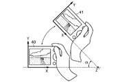
- FIG. 2A is a rear view showing an example of the appearance of the camera according to the present embodiment.
- a release button 2001 and a zoom lever 2002 for changing the focal length of the zoom lens of the optical system 1001 are provided on the upper surface of the camera.
- a mode dial 2003 for changing the imaging mode and a function button 2004 for making various settings including an up / down / left / right key and an enter key are provided on the back of the camera.
- a menu button 2005 for displaying various setting menus on the image display unit 1012 and a display button 2006 for switching display of the image display unit 1012 are further provided. These buttons, dials, and keys are all included in the operation unit 1017.
- the release button 2001 has a structure in which the first switch is turned on when the release button 2001 is pushed in half, and the second switch is turned on when the release button 2001 is pushed down to the end.
- the system control unit 1014 starts an imaging preparation operation including AE processing and AF processing. Then, the system control unit 1014 drives the aperture and lens included in the optical system 1001 via the drive control unit 1007 to form a subject image with appropriate brightness on the image sensor 1003.
- the system control unit 1014 starts an imaging operation (main imaging operation), opens the mechanical shutter 1002 through the drive control unit 1007, and opens an appropriate exposure time based on the AE process, and the imaging element. 1003 is exposed. Note that in the case where the imaging element 1003 has an electronic shutter function, a necessary exposure time may be ensured in combination with the mechanical shutter 1002.
- the image sensor 1003 is driven by a drive pulse generated from an operation pulse generated by a timing signal generator 1006 controlled by the system control unit 1014, photoelectrically converts the formed subject image into an electrical signal, Output as an analog image signal.
- the analog image signal output from the image sensor 1003 is converted into a digital image signal by the A / D converter 1005 after the clock synchronization noise is removed by the CDS circuit 1004 operated by the operation pulse generated by the timing signal generator 1006. Converted.
- image processing such as color conversion, white balance, and gamma correction, resolution conversion processing, and image processing are performed on the digital image signal output from the A / D converter 1005.
- Image data is generated by performing compression processing or the like.
- the image memory 1009 is used to temporarily store a digital image signal being processed by the signal processing unit 1008 or to store image data that is a digital image signal that has been processed.
- the image data generated by the signal processing unit 1008 is converted into data suitable for the recording medium 1010 (for example, file system data having a hierarchical structure) by the recording control unit 1011 and recorded on the recording medium 1010.
- the display control unit 1013 converts the image data into a signal suitable for the image display unit 1012 (for example, an NTSC analog signal) and displays the image data on the image display unit 1012.
- the signal processing unit 1008 may output the image data as it is to the image memory 1009 or the recording control unit 1011 without performing image processing on the digital image signal in accordance with a control signal from the system control unit 1014. . Further, when requested by the system control unit 1014, the signal processing unit 1008 receives information about digital image signals and image data generated in the process of signal processing, or information extracted from the information, and the system control unit 1014. Output to. Such information includes, for example, information on the spatial frequency of the image, the average pixel value in the designated area, and the data amount of the compressed image. Further, the recording control unit 1011 outputs information such as the type and free capacity of the recording medium 1010 to the system control unit 1014 in response to a request from the system control unit 1014.
- the recording control unit 1011 When reproducing the image data recorded on the recording medium 1010, the recording control unit 1011 reads out the image data to be reproduced from the recording medium 1010 according to a control signal from the system control unit 1014. Then, the signal processing unit 1008 performs image expansion processing when the image data is a compressed image in accordance with the control signal from the system control unit 1014, and stores it in the image memory 1009. Image data stored in the image memory 1009 is converted into a display resolution corresponding to the resolution of the image display unit 1012 by the signal processing unit 1008, and then converted into a signal suitable for the image display unit 1012 by the display control unit 1013. It is displayed on the image display unit 1012.
- the shake detection sensor 1018 is an acceleration sensor, detects an acceleration component of shake applied to the camera, and functions as shake detection means for detecting the shake operation of the camera.
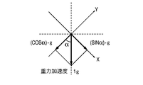
- the shake detection sensor 1018 can independently detect accelerations of the camera in three directions of the X-axis direction, the Y-axis direction, and the Z-axis direction in the coordinate system shown in FIG. 2B (referred to as a camera coordinate system). Yes, the posture of the camera as shown in FIG. 2B is called a normal position.
- the Y-axis direction is a direction opposite to gravity
- the Z-axis direction is parallel to the optical axis of the optical system 1001
- the X-axis direction is a direction orthogonal to the Y-axis and Z-axis. (Horizontal direction).
- the type, number, and arrangement of sensors are not particularly limited as long as vibrations in one or more specific directions can be detected.
- an angular velocity sensor or a gravity sensor can be used instead of the acceleration sensor.
- the camera has a camera shake detection sensor or a vertical / horizontal position detection sensor 1021, they may be used as the vibration detection sensor in this embodiment.
- the origin of the camera coordinate system is described so as to coincide with one vertex when the camera casing is regarded as a rectangular parallelepiped, but the position of the origin is not particularly limited.
- FIG. 4A to FIG. 4C are signal waveforms showing the time change of the X-axis direction component of the acceleration detected by the shake detection sensor 1018 when the camera is swung up or down.
- the horizontal axis represents time
- the vertical axis represents the acceleration component when the camera is swung up from a horizontal posture.
- FIG. 4A is a signal waveform showing the time change of the X-axis direction component of the acceleration when the camera is accelerated from the horizontal state at the start timing of swinging up, decelerated at the end of swinging up and stopped.
- acceleration is detected at the time of acceleration at the start of swing (peak 501) and at the time of deceleration at the end of swing (peak 502). Since the camera coordinate system shifts from the state shown in FIG. 3B to the state shown in FIG. 3C, the X-axis direction component of the gravitational acceleration in the stationary state before and after the swing starts from the 0g level as shown in FIG. ) ⁇ Changes to g level.
- FIG. 4B shows the time change of the X-axis component of the acceleration detected by the shake detection sensor 1018 when the camera is swung up and down from a state where it has been swung up, and decelerated and stopped when it has been swung down to a horizontal position. It is the signal waveform shown. That is, corresponding to the state shifted from the state 41 in FIG. 3A to the state 40, acceleration is detected at the beginning of swing (peak 503) and decelerated at the end of swing (peak 504). Since the camera coordinate system shifts from the state of FIG. 3C to the state of FIG. 3B, the X-axis direction component of the gravitational acceleration in the stationary state before and after swinging is from (sin ⁇ ) ⁇ g level as shown in FIG. Changes to 0g level.
- FIG. 4C shows a signal waveform indicating the time change of the X-axis component of the acceleration detected by the shake detection sensor 1018 when the camera is shaken up and subsequently shaken down.
- the signal waveform of FIG. 4C is a waveform obtained by adding the signal waveforms of FIGS. 4A and 4B.
- a peak 505 in FIG. 4C is an acceleration peak that appears due to acceleration when the swing-up operation is executed.
- a peak 506 is a peak of acceleration that appears when the deceleration at the time of swinging up and the acceleration at the time of swinging down are combined in a state where the swinging is finished and the swinging is about to be started.
- a peak 507 is a peak of acceleration that appears at the time of deceleration at the end of the swing-down operation.
- the peak 505 indicating the acceleration at the start of the swing-up is the first acceleration waveform
- the peak 506 obtained by combining the acceleration at the end of the swing-up and the start of the swing-down is the second acceleration waveform
- the peak indicating the acceleration at the end of the swing-down is the third acceleration waveform.
- the peak 506 which is the second acceleration waveform, tends to increase by the amount corresponding to the gravitational acceleration, and can be used effectively when detecting the motion of shaking the camera based on the acceleration.
- FIG. 4C shows the signal waveform of the acceleration detected by swinging up and then swinging down, but in the case of the swinging up and swinging up operation, the signal waveform has an opposite phase to the signal waveform shown in FIG. 4C. It becomes a waveform.
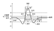
- FIG. 5A is an example of the signal waveform of the X-axis direction component of acceleration detected by the shake detection sensor 1018 (acceleration sensor in the present embodiment) when the camera is swung up and then swung down similarly to FIG. 4C.
- the horizontal axis represents time, and the vertical axis represents the output of the shake detection sensor 1018.
- the sign represents the direction of acceleration.
- the first threshold value A and threshold value -A are threshold values for determining whether or not the camera of this embodiment is moving. Specifically, the vibration determination unit 1019 determines that the camera is not moving if the absolute value of the acceleration detected by the shake detection sensor 1018 is less than A, and the absolute value of the acceleration is greater than or equal to the first threshold value. Then, it is determined that the camera is moving.
- the second threshold value B and threshold value -B are threshold values for determining whether the camera is shaken in a predetermined manner.
- the thresholds are set in a relationship of threshold-B ⁇ threshold-A and threshold A ⁇ threshold B. If the absolute value of the acceleration detected by the shake detection sensor 1018 is greater than or equal to the threshold A and less than the threshold B, the vibration determination unit 1019 determines that the camera is moving but is not being shaken in a predetermined manner. . On the other hand, if the absolute value of the acceleration detected by the shake detection sensor 1018 is greater than or equal to the threshold value B, the vibration determination unit 1019 determines that the camera is moving and is shaken in a predetermined manner.
- the third threshold value C and threshold value -C are threshold values for determining whether the camera is shaken within a predetermined strength range.
- the thresholds are set in a relationship of threshold-C ⁇ threshold-B and threshold B ⁇ threshold C. If the absolute value of the acceleration detected by the shake detection sensor 1018 is greater than or equal to the threshold value B and less than the threshold value C, the vibration determination unit 1019 is shaken within a predetermined swing method and a predetermined strength range. Is determined. On the other hand, if the absolute value of the acceleration detected by the shake detection sensor 1018 is greater than or equal to the threshold value C, the vibration determination unit 1019 determines that the camera shake is too strong.
- a warning message may be displayed on the image display unit 1012, or a warning sound may be emitted from a speaker (not shown).
- the vibration determination unit 1019 may compare the acceleration value detected by the shake detection sensor 1018 and the threshold value with an absolute value, and may compare the acceleration value with a positive / negative threshold value. For example, when comparing the detected acceleration with the first threshold, the vibration determination unit 1019 determines that the camera is not moving (was shaken) if the detected acceleration is greater than ⁇ A and less than + A. To do. The vibration determining unit 1019 determines that the camera is moving if the detected acceleration is ⁇ A or less or + A or more. The same applies to other threshold values.
- the peak 302 having the largest acceleration absolute value is the second peak in FIG. 4C. It corresponds to the acceleration waveform of. That is, when the purpose is to swing the camera down, the swing-down operation is shown. When the purpose is to swing up, the swing-up operation is shown.
- the peak 301 is the first acceleration waveform in FIG. 4C
- the target operation is a swing-down, it is an acceleration of the swing-up operation that is the preparation operation.
- a peak 303 is the third acceleration waveform in FIG.
- the waveform is a waveform when the deceleration at the time of swinging down is detected. If the target motion is a swing-up motion, the waveform is axisymmetric with respect to the X axis (positive and negative are reversed), and the first acceleration waveform 301 and the third acceleration waveform 303 are Upwards. Note that the waveform having the largest absolute value of acceleration does not necessarily indicate the intended operation. A method of detecting the intended operation in the present invention will be described later.
- the threshold S1 and the threshold S2 are thresholds for the time t1 when the second acceleration waveform representing the intended motion (main motion) is continuously equal to or higher than the threshold A or equal to or lower than the threshold ⁇ A.
- the vibration determination unit 1019 determines that the second acceleration waveform (main operation) has been detected when the condition of threshold S1 ⁇ time t1 ⁇ threshold S2 is satisfied.
- the vibration determination unit 1019 is a position where the swing motion is stopped when a state in which it is determined that the camera is not moving (a state in which the acceleration is greater than the threshold ⁇ A and less than the threshold A) has passed for a time equal to or longer than the threshold E It is determined that In this case, when the state in which the camera is determined not to move is a state in which the time equal to or longer than the time of the threshold E has not elapsed, the vibration determining unit 1019 first has the acceleration equal to or higher than the threshold A or lower than the threshold ⁇ A. It is determined that the operation started at the time is continued (one swing operation).
- the vibration determination unit 1019 determines, for example, the third acceleration waveform 303 in FIG. 5A as a series of operations with the first acceleration waveform 301 and the second acceleration waveform 302. If the acceleration is greater than the threshold value -A and less than the threshold value A from the time indicated by 314 after the time equal to or longer than the threshold value E, the acceleration is again reduced to the threshold value -A or more than the threshold value A. The determination unit 1019 determines that a new operation has been started.
- FIG. 5A shows a case where three sets of threshold values A, B, and C having the same absolute value are used as the acceleration level threshold value, one or more absolute values of the positive threshold value and the negative threshold value are different. Also good.
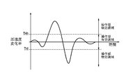
- FIG. 5B is a diagram showing the change over time in the acceleration signal change rate obtained by removing the offset component from the acceleration output signal shown in FIG. 5A.
- the acceleration signal change rate may be used as the threshold value for determining whether the camera is moving or not moving as described with reference to FIG. 5A.
- THh and THl are used instead of the threshold value ⁇ A in FIG. 5A.
- THh and THl may be used instead of ⁇ B and ⁇ C in FIG. 5A, and the threshold value of the acceleration signal change rate may be determined separately.
- the vibration determination unit 1019 determines whether or not the camera is vibrating in the axial direction based on an acceleration signal output or acceleration signal change rate in one axial direction as shown in FIG. 5A or 5B. The determination result is output to the system control unit 1014. Based on the determination result, the system control unit 1014 enables or disables the operation of the camera by the operation device included in the operation unit 1017.
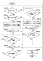
- FIG. 6 is a flowchart for explaining the outline of the user operation recognition process when the camera of the present embodiment is in the imaging mode.
- the vibration determination unit 1019 determines whether the camera is vibrating in the X-axis direction from the acceleration output signal in the X-axis direction of the shake detection sensor 1018 (S8001).
- the vibration determination unit 1019 determines, for example, whether the camera is vibrating in the X-axis direction based on the magnitude, direction, and frequency of the acceleration signal output or acceleration signal change rate peak in the X-axis direction.
- the vibration determination unit 1019 (1) A cycle in which the peak of the acceleration signal output or acceleration signal change rate in the X-axis direction deviates from a predetermined threshold range (A to -A for acceleration signal output, THh to THl for acceleration signal change rate) is predetermined Less than the period and (2) a state where continuous peaks satisfy the opposite direction continues for a certain period of time. Alternatively, when a predetermined number of continuous peaks satisfy the conditions (1) and (2), it is determined that the vibration is in the X-axis direction.
- a predetermined threshold range A to -A for acceleration signal output, THh to THl for acceleration signal change rate
- the vibration determination unit 1019 (A) When the acceleration signal output in the X-axis direction is out of a predetermined threshold range (for example, threshold value ⁇ A in FIG. 5A), it is determined that shake has been detected. (B) When it is determined that the shake is detected in (a), if a state in which the acceleration signal output in the X-axis direction is within a predetermined threshold range has passed for a predetermined time (for example, threshold E in FIG. 5A), It is determined that the swing motion has stopped. In the time from (a) to (b), the operation is continued even if the acceleration signal output in the X-axis direction is within a predetermined threshold range (for example, within the range of the threshold ⁇ A in FIG. 5A). It is determined that
- the vibration determination unit 1019 determines that the vibration is not performed in the X-axis direction.
- the vibration determination unit 1019 can similarly determine the Y-axis direction and the Z-axis direction. Note that this vibration determination method is merely an example, and the presence or absence of vibration may be determined by other methods.
- the vibration determining unit 1019 determines whether the camera is vibrating in the Y-axis direction from the acceleration output signal in the X-axis direction of the shake detection sensor 1018 (S8002). . If it is determined that the camera does not vibrate in the Y-axis direction, the vibration determination unit 1019 determines whether the camera is vibrating in the Z-axis direction from the acceleration output signal in the Z-axis direction of the shake detection sensor 1018 (S8003). ).
- the vibration determination unit 1019 outputs the determination result in each axis direction to the system control unit 1014. Then, when the system control unit 1014 obtains a determination result that it vibrates in any of the axial directions, the system control unit 1014 invalidates the operation of the camera by the operation unit 1017 (S8005). When the operation by the operation unit 1017 is invalid, the system control unit 1014 ignores the input from the operation unit 1017. Thus, for example, when the user tries to give a desired instruction by vibrating the camera, even if the operation unit 1017 such as the menu button 2005 or the mode dial 2003 is accidentally operated, the intention of the operation unit 1017 It is possible to prevent an input not to be made.
- the operation of the release button 2001 is not ignored by the system control unit 1014 even if the operation by the operation unit 1017 is invalidated. Whether the operation by the operation unit 1017 is valid or invalid can be stored, for example, in the RAM 1016 as a flag.
- the system control unit 1014 when recognizing vibration in a specific axial direction as an input of a command or instruction, the system control unit 1014 recognizes based on a detection result output from the vibration determination unit 1019. Process. Then, the system control unit 1014 executes an operation according to the recognized command or instruction.
- the vibration determination unit 1019 may output a determination result for each determination in each axial direction, or may output determinations for all axial directions collectively. Further, the vibration determination unit 1019 may output only the determination result in the axial direction in which it is determined that the object is vibrating. That is, if there is no axial direction that is determined to be vibrating, the determination result is not output. Alternatively, when it is determined that the vibration determination unit 1019 is vibrating in a certain axial direction, the determination process for the remaining axial direction may be omitted (recognizing a specific combination of vibration directions as an instruction input) Except when configured to do so).
- the system control unit 1014 validates the operation of the camera by the operation unit 1017 (S8004). Normally, the operation unit 1017 is effective. Therefore, if the operation is not invalidated, the system control unit 1014 does not need to perform the process for validating the operation in S8004.
- the system control unit 1014 determines whether an instruction to start imaging is input, specifically, whether the second switch of the release button 2001 is on (S8006). If the second switch is off, the processing from S8001 is repeated. When the second switch is on, the system control unit 1014 performs an imaging process even if the operation of the camera by the operation unit 1017 is invalid (S8007).
- imaging is executed when the second switch of the release button 2001 is detected to be turned on.
- the full press operation of the release button 2001 with the second switch turned on is considered to be highly likely to be an intentional operation rather than an erroneous operation.
- the turning on of the first switch by the half-press operation of the release button 2001 is ignored when the operation unit 1017 is invalidated.
- the first switch is kept on, vibrations in any of the X-axis, Y-axis, and Z-axis directions of the camera are not detected, and the camera operation by the operation unit 1017 becomes effective.
- the first switch is turned on.
- the system control unit 1014 starts an imaging preparation operation such as AF processing and AE processing.
- the user can instruct forward or reverse of images to be played back on the mobile device by shaking the mobile device (such as a camera that can set at least one of the playback mode and the imaging mode).
- the user can view the image recorded on the recording medium 1010 through the image display unit 1012 or the like by setting the portable device to the reproduction mode.
- the camera described in the first embodiment is used as an example of the portable device according to the present embodiment. Therefore, descriptions of the hardware configuration, the swing motion detection method, and the like are omitted.
- the camera swing motion is determined by detecting the acceleration in the X-axis direction.
- FIG. 7 is a flowchart for explaining processing related to one swing operation.
- the system control unit 1014 determines whether the camera is set to the playback mode (S700). If the playback mode is selected, the system control unit 1014 executes the processing from S701 onward. When the acceleration detected by the shake detection sensor 1018 crosses the threshold A or threshold ⁇ A shown in FIG. 5A (point 310 in FIG. 5A), the vibration determination unit 1019 detects that the camera has moved. When the vibration determination unit 1019 detects that the camera has moved (was shaken), the system control unit 1014 invalidates the operation by the operation unit 1017 (S702).
- Acceleration is detected in a detection cycle of a predetermined shake detection sensor 1018. Further, the vibration determination unit 1019 stores the detection value of the shake detection sensor 1018, and after the detection value falls below the threshold value -A at the point 310, the detection value obtained for each detection cycle is the peak value (minimum value). The peak value (minimum value) memorized is updated every time. Therefore, the vibration determination unit 1019 can measure the peak value (minimum value) of the detection value after the detection value falls below the threshold ⁇ A. The vibration determination unit 1019 can measure the peak value (maximum value) in the same manner for the upward peak.
- the vibration determination unit 1019 When it is detected that the camera has moved in S702 and the processing for detecting the motion is started, the vibration determination unit 1019 first performs first acceleration waveform detection. The vibration determination unit 1019 determines that the first acceleration waveform has been detected when the acceleration detected by the shake detection sensor 1018 crosses the threshold A or ⁇ A after it is determined that the camera has moved.
- the vibration determination unit 1019 When the first acceleration waveform is detected, the vibration determination unit 1019 subsequently performs a second acceleration waveform detection process. Next, when the detected acceleration crosses the threshold A (or -A) (point 311), the vibration determination unit 1019 detects the start of the second acceleration waveform. The vibration determination unit 1019 then detects the end of the second acceleration waveform when the detected acceleration crosses the threshold A (or -A) again at time t1 that satisfies the condition of threshold S1 ⁇ time t1 ⁇ threshold S2 (point 313). To do. As described above, if the time t1 does not satisfy the above condition, the vibration determination unit 1019 does not consider that the second acceleration waveform has been detected.
- the vibration determination unit 1019 shakes the camera correctly. (S703, Yes).
- the vibration determination unit 1019 determines whether the camera is swung up or down from the sign of the threshold B over which the second acceleration waveform is straddled. On the other hand, if the second acceleration waveform does not straddle the threshold value B (or -B) or reaches the threshold value C (or -C), the vibration determination unit 1019 determines that the camera has not been shaken correctly ( S703, No). In this case, the vibration determination unit 1019 determines whether the magnitude of the swing motion (the magnitude of the detected acceleration) is greater than a predetermined value (threshold value ⁇ C in FIG. 5) in S710.
- the vibration determination unit 1019 ends the swing motion detection in S708 (S708). Then, the system control unit 1014 enables the operation unit 1017 (S709). On the other hand, when the peak value of the second acceleration waveform reaches the threshold value C (or -C), the vibration determination unit 1019 issues a warning as described above (S710). Thereafter, the processing after S708 is as described above.
- the second acceleration waveform needs to be detected by a threshold having a different sign from the threshold used for detection of the first acceleration waveform. For example, when the first acceleration waveform is detected based on the threshold ⁇ A (when the first acceleration waveform is a downwardly convex peak), the second acceleration waveform is detected based on the threshold A. There is a need. This is because the first acceleration waveform corresponds to the preparatory operation before the main operation and is an operation opposite to the main operation.
- the system control unit 1014 displays the image displayed on the image display unit 1012 through the display control unit 1013 when the end of the second acceleration waveform is detected. Is changed (S704).
- the detection time point of the end of the second acceleration waveform is a time point (point 313 in FIG. 5) when the second acceleration waveform again crosses the threshold value A (or -A).
- it may be changed in the order of the file name and number, or may be changed in the order of the date and time of image capture and the date and time recorded on the recording medium 1010.
- the order of changing the image may be switched between the forward direction and the reverse direction according to the sign of the threshold value used for detecting the first or second acceleration waveform.
- the image to be displayed is changed regardless of the threshold code.
- the vibration determination unit 1019 determines whether or not the acceleration detected by the shake detection sensor 1018 is within a range greater than the threshold ⁇ A and less than the threshold A. While the state where the detected acceleration is in the range larger than the threshold value ⁇ A and smaller than the threshold value A continues, the vibration determination unit 1019 measures the shake duration time t2 (S706). Then, the vibration determination unit 1019 determines whether or not the shake continuation time t2 is greater than or equal to the threshold (S707). When the shake continuation time t2 is equal to or greater than the threshold value E, the vibration determination unit 1019 regards the camera as stationary and ends the detection of the swing motion (S708). Then, the system control unit 1014 validates the operation by the operation unit 1017 (S709).
- the operation of the camera by the operation unit 1017 is not validated unless the state in which the magnitude of acceleration (absolute value) is less than a predetermined value continues for a predetermined time or longer.
- the vibration determination unit 1019 determines that the swing operation is being performed until a predetermined time E has passed from the point 310 to the point 314. Therefore, even if the acceleration signal output in the X-axis direction is within the range of the threshold value ⁇ A, the operation by the operation unit 1017 is invalid until the state continues for a predetermined time E.
- the vibration determination unit 1019 initializes the shake duration time t2 (S712). Then, the process returns to S705, and the vibration determination unit 1019 determines again whether or not the absolute value of the detected acceleration is in a range less than the threshold value A.
- the vibration determination unit 1019 increases the value of the shake continuation time t2, while S705 Repeat the process from.
- the detected acceleration is the first. It is considered that the operation from the time point when the threshold A or -A is reached is continued (one swing operation). Therefore, it can be determined that the third acceleration waveform is a new swing motion.
- the camera according to the present embodiment performs a swing operation by determining an error if the acceleration is applied too short or too long or too strong, even if the detected acceleration is greater than a certain size. Is not detected. As a result, the waveform is detected more accurately, and an intuitive and easy-to-understand operation system is provided. If the stationary state does not last for a certain period of time, the first, second, and third acceleration waveforms corresponding to this operation from the preparatory operation can be accurately determined by assuming that one swing operation is continuing. Can be detected.
- the present embodiment it is possible to provide a camera that can change an image by shaking the camera in a predetermined direction while the image is displayed, such as in a playback mode. Further, even if the user operates the operation unit by mistake in the operation of shaking the camera, an instruction different from the user's intention is not reflected.
- the swing motion detection processing has been described by taking as an example the case where the display image changing function is assigned to the swing motion while an image is displayed in the playback mode.
- the same detection process can be performed when a function related to imaging in the imaging mode is assigned to the swing operation. That is, once it is determined that the camera has been moved, the operation by the operation unit is not validated if the time when the magnitude of the acceleration (absolute value) is smaller than a predetermined value does not elapse for a predetermined time.
- the second switch of the release button 2001 when the second switch of the release button 2001 is detected to be turned on, imaging is performed.
- the camera when the release button 2001 is operated in the playback mode, the camera may shift from the playback mode to the imaging mode. In this case, the on-state of the first switch due to the half-pressing operation of the release button 2001 in the playback mode is ignored. May be. In this case, while the first switch is kept on, vibrations in any of the X-axis, Y-axis, and Z-axis directions of the camera are not detected, and the camera operation by the operation unit 1017 is enabled. The first switch is turned on.
- an operation device provided on the top surface of the camera and an operation provided on the back surface of the operation unit 1017 according to the position of the camera (vertical position or horizontal position) and the detected direction of vibration. It is characterized by individually controlling validity / invalidity with a device.
- the operation device that controls validity / invalidity does not need to be used on the upper surface and the rear surface of the camera, and may be an operation device provided on an arbitrary surface of the camera housing. That is, this embodiment can be applied to an operation device provided on any one surface and the other surface among operation devices provided on at least two surfaces of the camera casing.
- FIG. 8A and FIG. 8B are flowcharts for explaining an overview of user operation recognition processing in the imaging mode of the camera according to the third embodiment of the present invention.
- the system control unit 1014 determines the posture of the camera from the output of the vertical / horizontal position detection sensor 1021 (S9001).
- the vibration determination unit 1019 determines whether the vibration is in the X-axis direction. (S9002).
- the system control unit 1014 invalidates the operation of the operation devices included in the operation unit 1017 provided on the upper surface of the camera and is provided on the rear surface of the camera.
- the operation of the operation device is valid (S9003). This is because when the camera is vibrated in the X-axis direction, it is considered highly likely that the operation device provided on the upper surface of the camera is erroneously operated.
- the system control unit 1014 determines whether or not the second switch of the release button 2001 is on (S9004), and performs an imaging operation when the second switch is on (S9008). When the second switch of the release button 2001 is off, the system control unit 1014 determines whether the operation device on the upper surface of the camera has been operated (S9005). If the operation device on the upper surface of the camera is not operated, the system control unit 1014 returns the process to the camera posture determination step (S9001).
- the system control unit 1014 determines whether or not the second switch of the release button 2001 is on (S9006), and performs the imaging operation if the second switch is on. (S9008).
- the system control unit 1014 determines whether a predetermined time has elapsed since the operation of the operation device on the upper surface of the camera was detected in S9005 (S9007). If the predetermined time has not elapsed, the system control unit 1014 continues the determination step of S9006. If the predetermined time has elapsed, the system control unit 1014 returns the process to the camera posture determination step (S9001).
- the vibration determination unit 1019 determines whether the camera is vibrating in the Y-axis or Z-axis direction (S9009). When it is determined that neither the Y-axis direction nor the Z-axis direction vibrates, the system control unit 1014 validates the operation of all operation devices included in the operation unit 1017 (S9013), and returns the process to S9001. . On the other hand, when it is determined that the camera vibrates in the Y-axis or Z-axis direction, the system control unit 1014 validates the operation of the operation device provided on the upper surface of the camera, and the operation device provided on the rear surface of the camera. The operation is invalidated (S9010). This is because when the camera is vibrated in the Y-axis or Z-axis direction, it is considered that there is a high possibility that an operation device provided on the back surface of the camera is erroneously operated.
- the system control unit 1014 determines whether or not the second switch of the release button 2001 is on (S9011), and when the second switch is on, performs an imaging operation (S9008).
- the system control unit 1014 determines whether the operation device on the back of the camera has been operated (S9012). If the operation device on the back of the camera is not operated, the system control unit 1014 returns the process to the camera posture determination step (S9001). When the operation device on the upper surface of the camera is operated, the system control unit 1014 executes the processes after S9006 described above.
- the camera posture is a position where the camera grip is above or below (typically 90 ° from the normal position with the optical axis of the lens as the rotation axis). Or a position rotated by -90 degrees).
- the vibration determination unit 1019 determines whether the camera is vibrated in any of the X axis, Y axis, or Z axis (S9014). If no vibration is detected in any axial direction, the system control unit 1014 validates the operation of all the operation devices included in the operation unit 1017 (S9013), and returns the process to S9001.
- the system control unit 1014 enables the operation of the operation device provided on the upper surface of the camera and is provided on the rear surface of the camera.
- the operation of the operation device is invalidated (S9015). If the camera is in a posture with the grip up or down, if the camera is vibrated in either direction, the operation device provided on the back of the camera is likely to be erroneously operated. Because.
- system control unit 1014 performs the same processing as S9011 and S9012 in S9016 and S9017.
- the operation of the operation device provided on the upper surface of the camera and the operation of the operation device provided on the rear surface according to the posture of the camera and the vibration direction of the camera. Enable / disable individually. Therefore, in addition to the effects of the first embodiment, fine control can be performed according to an operation device that is highly likely to be erroneously operated and an operation device that is not.
- the system control unit 1014 when vibrations in the X-axis, Y-axis, and Z-axis directions are detected in S9002 and S9009, the system control unit 1014 previously determines the vibration direction (or It is recognized as an instruction or command associated with a combination. Then, the system control unit 1014 executes an operation corresponding to the recognized instruction or command.
- the invalid time is set as the time during which the swing motion is detected. That is, when the acceleration signal output deviates from a predetermined threshold range (for example, less than the threshold ⁇ A in FIG. 5A), it is determined that the swing motion has started, and the state in which the acceleration signal output is within the predetermined threshold range is a predetermined time (for example, FIG. 5A If the threshold E) or more elapses, it is determined that the swing motion has stopped.
- a predetermined threshold range for example, less than the threshold ⁇ A in FIG. 5A
- step S701 in FIG. 7 is performed for each axial direction (S9002, S9009 in FIG. 8A, S9014 in FIG. 8B), and the process of invalidating the operation unit in step S702 in FIG. (S9003 in FIG. 8, S9010, S9015 in FIG. 8B).
- the first and third embodiments do not invalidate the operation corresponding to the imaging start instruction (full press of the release button 2001) among the operations of the operation device.
- the operation corresponding to the imaging start instruction may be invalidated.
- S8005 of the first embodiment the operation of all the operation devices is invalidated
- S9003 of the third embodiment it is provided on the upper surface of the camera including the full press of the release button 2001. All operation of the operation device is invalid.
- the present invention can also be realized by executing the following processing. That is, software (program) that realizes the functions of the above-described embodiments is supplied to a system or apparatus via a network or various storage media, and a computer (or CPU, MPU, or the like) of the system or apparatus reads the program. It is a process to be executed.
Landscapes
- Engineering & Computer Science (AREA)
- Multimedia (AREA)
- Signal Processing (AREA)
- Physics & Mathematics (AREA)
- General Physics & Mathematics (AREA)
- Human Computer Interaction (AREA)
- Studio Devices (AREA)
- User Interface Of Digital Computer (AREA)
Priority Applications (7)
| Application Number | Priority Date | Filing Date | Title |
|---|---|---|---|
| EP10741088.8A EP2397897B1 (en) | 2009-02-12 | 2010-02-10 | Image pickup device and control method thereof |
| RU2011137460/08A RU2502117C2 (ru) | 2009-02-12 | 2010-02-10 | Устройство для захвата изображения и способ управления им |
| CN201080007686.7A CN102317857B (zh) | 2009-02-12 | 2010-02-10 | 摄像设备及其控制方法 |
| KR1020137025729A KR101352879B1 (ko) | 2009-02-12 | 2010-02-10 | 전자장치 및 그 제어 방법 |
| KR1020117020964A KR101352877B1 (ko) | 2009-02-12 | 2010-02-10 | 촬상장치 및 그 제어 방법 |
| US13/194,304 US8666239B2 (en) | 2009-02-12 | 2011-07-29 | Image capturing apparatus and control method thereof |
| US14/166,902 US8929725B2 (en) | 2009-02-12 | 2014-01-29 | Image capturing apparatus and control method thereof |
Applications Claiming Priority (6)
| Application Number | Priority Date | Filing Date | Title |
|---|---|---|---|
| JP2009-030469 | 2009-02-12 | ||
| JP2009030469 | 2009-02-12 | ||
| JP2009-034027 | 2009-02-17 | ||
| JP2009034027 | 2009-02-17 | ||
| JP2010-027001 | 2010-02-09 | ||
| JP2010027001A JP5357800B2 (ja) | 2009-02-12 | 2010-02-09 | 電子機器およびその制御方法 |
Related Child Applications (1)
| Application Number | Title | Priority Date | Filing Date |
|---|---|---|---|
| US13/194,304 Continuation US8666239B2 (en) | 2009-02-12 | 2011-07-29 | Image capturing apparatus and control method thereof |
Publications (1)
| Publication Number | Publication Date |
|---|---|
| WO2010092808A1 true WO2010092808A1 (ja) | 2010-08-19 |
Family
ID=42561656
Family Applications (1)
| Application Number | Title | Priority Date | Filing Date |
|---|---|---|---|
| PCT/JP2010/000825 WO2010092808A1 (ja) | 2009-02-12 | 2010-02-10 | 撮像装置およびその制御方法 |
Country Status (7)
Cited By (2)
| Publication number | Priority date | Publication date | Assignee | Title |
|---|---|---|---|---|
| JP2014112308A (ja) * | 2012-12-05 | 2014-06-19 | Fuji Xerox Co Ltd | 操作制御プログラム及び情報処理装置 |
| JP2019179454A (ja) * | 2018-03-30 | 2019-10-17 | オムロン株式会社 | センサ、情報処理装置、センサ制御方法、情報処理方法、プログラム、および記録媒体 |
Families Citing this family (15)
| Publication number | Priority date | Publication date | Assignee | Title |
|---|---|---|---|---|
| JP5532033B2 (ja) | 2011-09-16 | 2014-06-25 | カシオ計算機株式会社 | 撮像装置、撮像方法、及びプログラム |
| CA2763649A1 (fr) * | 2012-01-06 | 2013-07-06 | 9237-7167 Quebec Inc. | Camera panoramique |
| US20130254674A1 (en) * | 2012-03-23 | 2013-09-26 | Oracle International Corporation | Development mode activation for a mobile device |
| KR101880636B1 (ko) * | 2012-07-25 | 2018-07-20 | 삼성전자주식회사 | 디지털 촬영 장치 및 그의 제어 방법 |
| CN103685712A (zh) * | 2012-09-25 | 2014-03-26 | 腾讯科技(深圳)有限公司 | 移动终端浏览器页面刷新方法及移动终端 |
| GB2508341A (en) * | 2012-11-27 | 2014-06-04 | Samsung Electronics Uk Ltd | Capturing images using a predetermined motion to activate a button |
| CN103049100B (zh) * | 2012-12-06 | 2016-05-25 | 惠州Tcl移动通信有限公司 | 一种基于移动终端调整照片回显时间的方法及移动终端 |
| CN104104856B (zh) * | 2013-04-09 | 2016-08-10 | 腾讯科技(深圳)有限公司 | 图像采集方法、装置及电子设备 |
| EP3048481A4 (en) * | 2013-09-20 | 2017-05-10 | NEC Solution Innovators, Ltd. | Electronic device, method for controlling electronic device, and storage medium |
| JP6222830B2 (ja) * | 2013-12-27 | 2017-11-01 | マクセルホールディングス株式会社 | 画像投射装置 |
| KR20160135476A (ko) * | 2015-05-18 | 2016-11-28 | 삼성전자주식회사 | 전자 장치 및 그의 카메라 제어 방법 |
| JP6695209B2 (ja) * | 2016-04-28 | 2020-05-20 | シャープ株式会社 | 情報処理装置、携帯端末、機能実行方法、プログラム |
| US9948832B2 (en) * | 2016-06-22 | 2018-04-17 | Light Labs Inc. | Methods and apparatus for synchronized image capture in a device including optical chains with different orientations |
| CN114207656A (zh) * | 2019-08-14 | 2022-03-18 | 本田技研工业株式会社 | 信息提供系统、信息终端以及信息提供方法 |
| CN113676624A (zh) * | 2021-06-30 | 2021-11-19 | 西人马帝言(北京)科技有限公司 | 一种图像获取方法、装置、设备及存储介质 |
Citations (6)
| Publication number | Priority date | Publication date | Assignee | Title |
|---|---|---|---|---|
| JPH05103254A (ja) * | 1991-10-11 | 1993-04-23 | Hitachi Ltd | Vtr一体型カメラ |
| JPH11168644A (ja) * | 1997-12-03 | 1999-06-22 | Casio Comput Co Ltd | カメラ装置 |
| JP2000125184A (ja) | 1998-10-20 | 2000-04-28 | Fuji Photo Film Co Ltd | カメラ |
| JP2009030469A (ja) | 2007-07-25 | 2009-02-12 | Daikin Ind Ltd | スクロール圧縮機 |
| JP2009034027A (ja) | 2007-08-01 | 2009-02-19 | Minoru Industrial Co Ltd | 土壌消毒機 |
| JP2010027001A (ja) | 2008-07-24 | 2010-02-04 | Dainippon Printing Co Ltd | Icカードとそのプログラム、及び、icカードの発行方法 |
Family Cites Families (10)
| Publication number | Priority date | Publication date | Assignee | Title |
|---|---|---|---|---|
| JPH0764754A (ja) * | 1993-08-24 | 1995-03-10 | Hitachi Ltd | 小型情報処理装置 |
| JP3990744B2 (ja) * | 1995-09-08 | 2007-10-17 | キヤノン株式会社 | 電子機器及びその制御方法 |
| FI20001506L (fi) * | 1999-10-12 | 2001-04-13 | J P Metsaevainio Design Oy | Kädessäpidettävän laitteen toimintamenetelmä |
| US6937272B1 (en) * | 2000-11-08 | 2005-08-30 | Xerox Corporation | Display device for a camera |
| FI117488B (fi) * | 2001-05-16 | 2006-10-31 | Myorigo Sarl | Informaation selaus näytöllä |
| US20040070675A1 (en) * | 2002-10-11 | 2004-04-15 | Eastman Kodak Company | System and method of processing a digital image for intuitive viewing |
| US7173604B2 (en) * | 2004-03-23 | 2007-02-06 | Fujitsu Limited | Gesture identification of controlled devices |
| GB0503253D0 (en) * | 2005-02-17 | 2005-03-23 | Univ Northumbria Newcastle | User control of a hand-held device |
| JP2008151822A (ja) * | 2006-12-14 | 2008-07-03 | Pentax Corp | 像ブレ補正装置 |
| JP5117288B2 (ja) | 2008-06-12 | 2013-01-16 | オリンパスイメージング株式会社 | 撮影装置および撮影装置の設定方法 |
-
2010
- 2010-02-09 JP JP2010027001A patent/JP5357800B2/ja not_active Expired - Fee Related
- 2010-02-10 KR KR1020137025729A patent/KR101352879B1/ko not_active Expired - Fee Related
- 2010-02-10 EP EP10741088.8A patent/EP2397897B1/en active Active
- 2010-02-10 CN CN201080007686.7A patent/CN102317857B/zh active Active
- 2010-02-10 WO PCT/JP2010/000825 patent/WO2010092808A1/ja active Application Filing
- 2010-02-10 KR KR1020117020964A patent/KR101352877B1/ko not_active Expired - Fee Related
- 2010-02-10 RU RU2011137460/08A patent/RU2502117C2/ru not_active IP Right Cessation
-
2011
- 2011-07-29 US US13/194,304 patent/US8666239B2/en not_active Expired - Fee Related
-
2014
- 2014-01-29 US US14/166,902 patent/US8929725B2/en active Active
Patent Citations (6)
| Publication number | Priority date | Publication date | Assignee | Title |
|---|---|---|---|---|
| JPH05103254A (ja) * | 1991-10-11 | 1993-04-23 | Hitachi Ltd | Vtr一体型カメラ |
| JPH11168644A (ja) * | 1997-12-03 | 1999-06-22 | Casio Comput Co Ltd | カメラ装置 |
| JP2000125184A (ja) | 1998-10-20 | 2000-04-28 | Fuji Photo Film Co Ltd | カメラ |
| JP2009030469A (ja) | 2007-07-25 | 2009-02-12 | Daikin Ind Ltd | スクロール圧縮機 |
| JP2009034027A (ja) | 2007-08-01 | 2009-02-19 | Minoru Industrial Co Ltd | 土壌消毒機 |
| JP2010027001A (ja) | 2008-07-24 | 2010-02-04 | Dainippon Printing Co Ltd | Icカードとそのプログラム、及び、icカードの発行方法 |
Non-Patent Citations (1)
| Title |
|---|
| See also references of EP2397897A4 |
Cited By (2)
| Publication number | Priority date | Publication date | Assignee | Title |
|---|---|---|---|---|
| JP2014112308A (ja) * | 2012-12-05 | 2014-06-19 | Fuji Xerox Co Ltd | 操作制御プログラム及び情報処理装置 |
| JP2019179454A (ja) * | 2018-03-30 | 2019-10-17 | オムロン株式会社 | センサ、情報処理装置、センサ制御方法、情報処理方法、プログラム、および記録媒体 |
Also Published As
| Publication number | Publication date |
|---|---|
| KR101352879B1 (ko) | 2014-01-20 |
| EP2397897B1 (en) | 2016-12-28 |
| RU2502117C2 (ru) | 2013-12-20 |
| JP5357800B2 (ja) | 2013-12-04 |
| KR20130114757A (ko) | 2013-10-17 |
| RU2011137460A (ru) | 2013-03-20 |
| CN102317857B (zh) | 2014-07-30 |
| KR20110113770A (ko) | 2011-10-18 |
| US8666239B2 (en) | 2014-03-04 |
| EP2397897A1 (en) | 2011-12-21 |
| US20110280556A1 (en) | 2011-11-17 |
| CN102317857A (zh) | 2012-01-11 |
| EP2397897A4 (en) | 2012-08-01 |
| US20140186016A1 (en) | 2014-07-03 |
| JP2010220202A (ja) | 2010-09-30 |
| KR101352877B1 (ko) | 2014-01-20 |
| US8929725B2 (en) | 2015-01-06 |
Similar Documents
| Publication | Publication Date | Title |
|---|---|---|
| JP5357800B2 (ja) | 電子機器およびその制御方法 | |
| US8587676B2 (en) | Digital image processing apparatus including handshake correction module and methods of controlling the digital image processing apparatus | |
| TWI326553B (en) | Imaging apparatus, data extraction method, and data extraction program | |
| JP5686244B2 (ja) | 表示制御装置、表示制御方法、及び、プログラム | |
| KR101532610B1 (ko) | 디지털 촬영 장치, 디지털 촬영 장치 제어 방법, 및 컴퓨터판독가능 저장매체 | |
| JP2013017165A (ja) | 撮像装置 | |
| JP2012095167A (ja) | 撮像装置 | |
| CN101459770A (zh) | 数字拍摄设备及其控制方法 | |
| JP2006033724A (ja) | 情報処理装置及び情報処理方法 | |
| JP2013090056A (ja) | 画像再生装置及びカメラ | |
| JP5736014B2 (ja) | 電子機器およびその制御方法 | |
| JP4471882B2 (ja) | 表示装置および表示方法 | |
| JP2012114677A (ja) | 撮像装置、撮像方法及びプログラム | |
| JP5375368B2 (ja) | 撮像装置 | |
| JP4515005B2 (ja) | 電子カメラ | |
| US8050548B2 (en) | Control apparatus, imaging apparatus, and control method for the imaging apparatus | |
| JP6057529B2 (ja) | 撮像装置及び撮像方法 | |
| JP5495579B2 (ja) | 検出装置及び検出装置の制御方法 | |
| JP2008064874A (ja) | 撮像装置 | |
| JP2010193069A (ja) | 検出装置及び検出方法及びプログラム | |
| JP2010217778A (ja) | 撮像装置 | |
| JP2012063422A (ja) | 制御装置及びレンズ鏡筒 | |
| JP2010193068A (ja) | 検出装置及び検出方法及びプログラム | |
| JP2012039395A (ja) | 撮影機器 | |
| JP2010226554A (ja) | カメラおよび被写体追尾方法 |
Legal Events
| Date | Code | Title | Description |
|---|---|---|---|
| WWE | Wipo information: entry into national phase |
Ref document number: 201080007686.7 Country of ref document: CN |
|
| 121 | Ep: the epo has been informed by wipo that ep was designated in this application |
Ref document number: 10741088 Country of ref document: EP Kind code of ref document: A1 |
|
| REEP | Request for entry into the european phase |
Ref document number: 2010741088 Country of ref document: EP |
|
| WWE | Wipo information: entry into national phase |
Ref document number: 2010741088 Country of ref document: EP |
|
| NENP | Non-entry into the national phase |
Ref country code: DE |
|
| ENP | Entry into the national phase |
Ref document number: 20117020964 Country of ref document: KR Kind code of ref document: A |
|
| WWE | Wipo information: entry into national phase |
Ref document number: 2011137460 Country of ref document: RU |