WO2010090339A1 - 硬化肉盛溶接複合ワイヤ、これを用いたシンターケーキ支持スタンド、及び下方吸引式焼結機 - Google Patents
硬化肉盛溶接複合ワイヤ、これを用いたシンターケーキ支持スタンド、及び下方吸引式焼結機 Download PDFInfo
- Publication number
- WO2010090339A1 WO2010090339A1 PCT/JP2010/052005 JP2010052005W WO2010090339A1 WO 2010090339 A1 WO2010090339 A1 WO 2010090339A1 JP 2010052005 W JP2010052005 W JP 2010052005W WO 2010090339 A1 WO2010090339 A1 WO 2010090339A1
- Authority
- WO
- WIPO (PCT)
- Prior art keywords
- stand
- sinter cake
- support stand
- sintering machine
- cake support
- Prior art date
- Legal status (The legal status is an assumption and is not a legal conclusion. Google has not performed a legal analysis and makes no representation as to the accuracy of the status listed.)
- Ceased
Links
Images
Classifications
-
- B—PERFORMING OPERATIONS; TRANSPORTING
- B23—MACHINE TOOLS; METAL-WORKING NOT OTHERWISE PROVIDED FOR
- B23K—SOLDERING OR UNSOLDERING; WELDING; CLADDING OR PLATING BY SOLDERING OR WELDING; CUTTING BY APPLYING HEAT LOCALLY, e.g. FLAME CUTTING; WORKING BY LASER BEAM
- B23K35/00—Rods, electrodes, materials, or media, for use in soldering, welding, or cutting
- B23K35/22—Rods, electrodes, materials, or media, for use in soldering, welding, or cutting characterised by the composition or nature of the material
- B23K35/24—Selection of soldering or welding materials proper
- B23K35/30—Selection of soldering or welding materials proper with the principal constituent melting at less than 1550°C
- B23K35/3053—Fe as the principal constituent
- B23K35/308—Fe as the principal constituent with Cr as next major constituent
-
- F—MECHANICAL ENGINEERING; LIGHTING; HEATING; WEAPONS; BLASTING
- F27—FURNACES; KILNS; OVENS; RETORTS
- F27B—FURNACES, KILNS, OVENS OR RETORTS IN GENERAL; OPEN SINTERING OR LIKE APPARATUS
- F27B21/00—Open or uncovered sintering apparatus; Other heat-treatment apparatus of like construction
- F27B21/02—Sintering grates or tables
Definitions
- the present invention relates to a cured overlay welding composite wire for a sinter cake support stand (hereinafter referred to as “stand” as appropriate) used in a downward suction type sintering machine for producing a sintered ore to be used in a steelmaking process in a steel mill,
- the present invention relates to a sinter cake support stand using the above and a downward suction type sintering machine.
- the cross section is trapezoidal as a method to prevent deterioration of air permeability due to compression of the sintered ingot (sinter cake) by its own weight and improve productivity
- a plate-like support member (stand) having a height of 200 to 400 mm is erected vertically so as to be embedded in the raw material packed layer and arranged in parallel with the traveling direction of the sintering pallet.
- Patent Document 1 discloses a method of improving the air permeability and the excavation property by improving the shape of the stand and the arrangement method.
- Patent Document 2 discloses a technique for extending the life of a stand by using special cast steel as an appropriate material for the stand.
- Patent Document 3 discloses a technique for further extending the life of the stand by performing wear-resistant overlay welding on the ridge line portion and / or the side surface portion of the upper blade portion of the stand.
- the process of sintering the sintering raw material layer in the sintering pallet as a form in which the stand disposed in the sintering layer deteriorates, in addition to the occurrence and progress of cracks due to the operational thermal cycle, Corrosion and wear caused by the stand rubbing against the sintered ore in a high temperature oxidizing and / or sulfiding atmosphere.
- Patent Document 4 in order to prevent the deterioration of the stand and improve the service life, a range of up to 50% in area from the upper top of the side surface of the upper blade portion of the stand in advance to a thickness of 2 to A method is disclosed in which the thickness is reduced (skin cut) by 10 mm, and overlay welding is performed on the reduced thickness (skin cut) portion to eliminate the reduced thickness portion.
- the method described in Patent Document 4 has a certain effect as a measure for extending the life of the stand.
- a general high chromium cast iron-based hardfacing welded composite wire is designed to exhibit the performance of the surfacing metal with a thickness of 10 mm or more.
- a general high chromium cast iron-based hardfacing welded composite wire is not a material for the stand, it is not excellent in wear resistance and corrosion resistance in a high temperature atmosphere of the surfacing part.
- the present invention improves the wear resistance and corrosion resistance of the built-up part in a high temperature atmosphere by optimizing the component composition of the hardfacing welded composite wire for the stand, and prolongs the life of the stand.
- an object of the present invention is to provide a stand that can increase the replacement period of the stand and contribute to productivity improvement in the production of sintered ore.
- the present inventors diligently studied about the component composition of the cured built-up composite wire for a stand having excellent wear resistance and corrosion resistance in a high temperature atmosphere. As a result, the present inventors have found a component composition that improves wear resistance and corrosion resistance.
- the present invention has been made based on the above findings, and the gist thereof is as follows.
- a sinter cake support stand provided on a sintering pallet of a downward suction type sintering machine and comprising a blade portion for supporting a sinter cake during the production of sinter ore and a pedestal portion for mounting on the sintering pallet .
- a sinter cake support stand wherein the hardened welded composite wire of (1) above is welded to a thinned part formed by thinning the upper edge of the blade part.
- the upper part of the blade welded with the hardfacing welded composite wire is reinforced so as to exhibit excellent wear resistance and corrosion resistance. Therefore, the life of the stand will be dramatically extended. As a result, productivity in sinter production is improved.
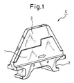
- FIG. 1 is a perspective view of a sinter cake support stand material.
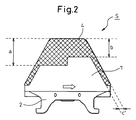
- FIG. 2 is a plan view of the stand after overlay welding is performed on the stand material of FIG. 1.
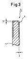
- FIG. 3 is a partial cross-sectional view of the blade portion of FIG.
- the stand S is a member that is mounted on the sintering pallet and supports the sinter cake in order to ensure the air permeability of the sintering raw material layer in the sintering pallet when the sintered ore is manufactured by the downward suction type sintering machine. It is.
- the stand S is made of stainless cast steel (SCS2), austenitic cast steel, or ferritic and austenitic duplex cast steel, and is attached to the pallet truck and the blade portion 1 that supports the sinter cake. It is comprised from the base part 2.
- SCS2 stainless cast steel
- austenitic cast steel or ferritic and austenitic duplex cast steel
- the arrow written at the center lower part of the blade part 1 indicates the traveling direction of the sinter cake. Since the blade part 1 supports the sinter cake in order to maintain the air permeability of the lower layer of the sintering raw material layer, the upper edge part that is a part in contact with the sinter cake, that is, the substantially trapezoidal upper side part and both oblique side parts It is necessary to reinforce. Therefore, the upper edge of the blade portion 1 and both surfaces (the front side surface and the back side surface in FIG. 2) are skin-cut to form the thinned portion 3, and the thinned portion 3 includes the blade portion 1. For reinforcement, weld metal 4 (shaded portion in FIG.
- the components of the composite wire are (A) C: 3-6%, (B) Si: 0.8-2%, (C) Cr: 20-30%, ( D) Mo: 4 to 8%, (E) Nb: 3 to 8%, B: 0.4% or less (including 0), (F) Nb: 8% or less (0 And B: contains 0.2 to 0.4%, and the amount of filler is adjusted and filled so that the balance becomes Fe, Mn, and unavoidable impurities. Inevitable impurities are, for example, P and S. “%” Means “% by mass” (hereinafter the same).
- C combines with carbide-forming elements such as Cr, Mo, Nb, and B to precipitate high-hardness carbides and contributes to improved wear resistance.
- the C content is 3 to 6% from the viewpoint of precipitation of carbides and peeling of the built-up portion.
- Si is an element effective for deoxidation during welding. If the addition is 0.8% or less, deoxidation becomes insufficient, and the effect of improving wear resistance and corrosion resistance due to precipitation of other elements cannot be sufficiently obtained. When it is more than 2%, the toughness of the weld metal tends to decrease.
- the Si content is set to 0.8 to 2%.
- Cr combines with C to precipitate high-hardness Cr carbide and improves wear resistance. Furthermore, corrosion resistance is also improved by Cr carbide. If the Cr content of the weld metal is less than 20%, the amount of precipitated carbide is small, so that sufficient wear resistance cannot be obtained. If it exceeds 30%, the amount of precipitated carbide becomes excessive, so the weld metal become brittle. Therefore, considering the intrusion of Cr from the cast stainless steel, the Cr content is 20 to 30%. Mo forms carbides, improves wear resistance in a high temperature atmosphere, and improves toughness and corrosion resistance of the matrix. If the addition is less than 4%, sufficient characteristics cannot be obtained. Adding over 8% only saturates the effect of the addition.
- the Mo content is 4 to 8%.
- Nb is an element that has a high affinity with carbon, forms carbides, and improves wear resistance in a high-temperature atmosphere. If the addition is less than 3%, the amount of precipitated carbide is small and a sufficient effect cannot be obtained. Adding over 8% only saturates the effect of the addition. Therefore, the Nb content is 3 to 8%.
- B is an element that precipitates a high-hardness boride, cures the matrix, and improves wear resistance. B is also an element that promotes precipitation of carbides such as chromium carbide. If the addition is less than 0.2%, the effect of addition cannot be obtained.
- the B content is 0.2 to 0.4%.
- Nb and B are both elements that improve the wear resistance. If either one of the above contents is contained, the other may be added within a range not exceeding the upper limit. That is, the contents of Nb and B are (E) Nb: 3 to 8% and B: 0.4% or less (including 0) or (F) Nb: 8% or less (including 0) And B: Any of 0.2 to 0.4% may be satisfied.
- the balance of the hardfacing welded composite wire of the present invention is Fe, Mn, and inevitable impurities.
- the Mn content is not particularly defined as long as it is brought in from ferroalloy or the like used as a filler, since it does not affect the wear resistance and corrosion resistance of the stand. However, if the Mn content is too large, it causes an increase in cost, so the content is preferably 3% or less, and more preferably 1% or less.
- the weld metal 4 as a reinforcing portion is formed on the thinned portion 3 so as not to protrude from the stand material, so the resistance to exhausting is reduced, so the wear resistance of the blade portion 1 is further improved.
- the weld metal 4 is formed with a step so that the build-up portion on the front side in the travel direction is larger than the front side in the travel direction, so that the build-up portion on the side in contact with the sintered ore is further increased. Therefore, the wear resistance and corrosion resistance of the blade portion 1 are further improved.
- the stand built-up welded with the hardfacing welded composite wire of the present invention has a longer life span than the stand built-up welded with a general high chromium cast iron hardened composite wire. Since the replacement cycle can be lengthened, productivity in the production of sintered ore is improved.
- the build-up material A is a high chrome cast iron-based hardfacing composite wire that has been conventionally used as a build-up welding material for forming the weld metal of the stand.
- the build-up materials B to N are composite wires composed of a filler containing C, Si, Cr, Mo, Nb, and B and a low carbon steel hoop.
- the cladding material O is a composite wire composed of a filler containing C, Si, Cr, Mo, and B and a low carbon steel hoop.
- the build-up material P is a composite wire composed of a filler containing C, Si, Cr, Mo, and Nb and a low carbon steel hoop.
- the thickness of the thinned portion 3 formed on the blade portion 1 was 3 mm.
- the width in FIG. 2 was 150 mm, b was 200 mm, and c was 20 mm.
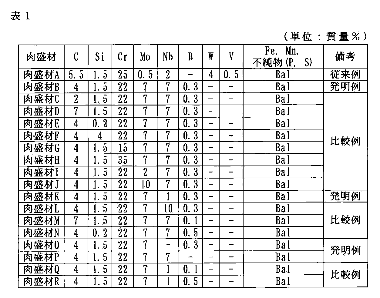
- the build-up material having the composition shown in Table 1 was subjected to build-up welding with a thickness of 3 mm equivalent to the reduced thickness, and 16 types of stands were made as trials. These stands were mounted on a sintering pallet of a lower suction type sintering machine.
- the used sintering machine has a pallet width of 5 m, an effective area of 660 m 2 , a sintering raw material thickness of 700 mm, a pallet speed of 4 m / min, and a production efficiency of 32 t / m 2 . Every six months after the stand was installed, the wear reduction height was measured and the damage status was confirmed. Table 2 shows the results from the start of use until 2 years later.
- the wear reduction height is the thickness reduction in the height direction, that is, the degree of reduction in height from the base portion of the stand to the upper side.
- build-up materials B, K, O, and P are examples of the present invention.
- the cladding material A is a high chromium cast iron-based hardfacing composite wire that has been conventionally used as a cladding material for forming the weld metal of the stand.
- the cladding material C is a comparative example in which the amount of C is less than the lower limit defined in the present invention.
- the build-up material D is a comparative example in which the amount of C exceeds the upper limit defined in the present invention.
- the build-up material E is a comparative example in which the amount of Si is less than the lower limit defined in the present invention.
- the build-up material F is a comparative example in which the Si amount exceeds the upper limit defined in the present invention.
- the build-up material G is a comparative example in which the Cr amount is less than the lower limit value defined in the present invention.
- the build-up material H is a comparative example in which the Cr amount exceeds the upper limit defined in the present invention.
- the build-up material I is a comparative example in which the amount of Mo is less than the lower limit specified in the present invention.
- the cladding material J is a comparative example in which the amount of Mo exceeds the upper limit value defined in the present invention.
- the build-up material L is a comparative example in which the amount of Nb exceeds the upper limit defined in the present invention.
- the build-up material M is a comparative example in which the amount of C exceeds the upper limit defined in the present invention.
- the build-up material N is a comparative example in which the amount of Si is less than the lower limit defined in the present invention and the amount of B exceeds the upper limit defined in the present invention.
- the cladding material Q is a comparative example in which the Nb amount is less than the lower limit value defined in the present invention and the B amount is less than the lower limit value defined in the present invention.
- the build-up material R is a comparative example in which the Nb amount is less than the lower limit value defined in the present invention and the B amount exceeds the upper limit value defined in the present invention.
- large wear means that there was more than 70 mm of wear with respect to the height at the time of mounting, and during wear means that there was wear of 30 to 70 mm with respect to the height at the time of mounting.
- the small wear means that there was wear of less than 30 mm with respect to the height at the time of mounting.
- the build-up materials B, K, O, and P which are the build-up materials of the present invention, are applied to the blade portion of the material shape shown in FIG. 1 in the manner shown in FIGS.
- the weld metal formed by overlay welding has excellent wear resistance and corrosion resistance, and has a life of about four times the wear reduction of the conventional stand.
- the overlay material J has an Mo amount exceeding the upper limit defined in the present invention.
- the weld metal formed by overlay welding the overlay material J is wear resistant as in the invention examples. Excellent in corrosion resistance and corrosion resistance.
- the build-up material J has an Nb amount exceeding the upper limit defined in the present invention, but the weld metal formed by overlay welding the build-up material L is wear resistant as in the invention example. Excellent in corrosion resistance and corrosion resistance. This is because even if Nb is added in a large amount, the effect of addition of Nb is only saturated, and the wear resistance and corrosion resistance are not adversely affected.
- the build-up material L is expensive because Nb is added in a large amount. Therefore, the build-up material L is not included in the scope of the present invention.
- the wear resistance and corrosion resistance of the stand used in the downward suction type sintering machine for producing the sintered ore used for the iron making process in the steelworks can be improved. improves. Since a large number of stands are arranged in the sintering machine, the life of the stands can be extended and the cost of replacing the stands can be reduced by adopting the stands using the cured overlay welding composite wire of the present invention. Can do. Therefore, according to the present invention, a great economic effect can be obtained.
Landscapes
- Engineering & Computer Science (AREA)
- Mechanical Engineering (AREA)
- General Engineering & Computer Science (AREA)
- Nonmetallic Welding Materials (AREA)
- Manufacture And Refinement Of Metals (AREA)
Abstract
Description
特許文献1には、スタンドの形状、及び、配置方法を改良し、通気性と排鉱性を改善する方法が開示されている。
特許文献2には、スタンドの適切な材料として、特殊鋳鋼を採用してスタンドの寿命を延長させる手法が開示されている。
特許文献3には、スタンドの上部ブレード部の稜線部、及び/又は、側面部に耐摩耗肉盛溶接を施すことによって、スタンドの寿命のさらなる延長を実現する手法が開示されている。
焼結パレット内の焼結原料層を焼結する工程で、焼結層内に配設されるスタンドが劣化する形態としては、操業上の熱サイクルに起因する割れの発生及び進行のほかに、高温の酸化及び/又は硫化雰囲気において、スタンドが焼結鉱と擦れ合うことによって生じる腐食及び摩耗があげられる。
特許文献4には、スタンドの劣化を防止し、寿命を向上させるために、スタンドの上部ブレード部の側面における上側頂部から、面積で高々50%までの範囲を、あらかじめ、片面あたり厚さ2~10mm減肉(スキンカット)し、該減肉(スキンカット)部に肉盛溶接を施して、減肉部を消滅させる方法が開示されている。特許文献4に記載の方法は、スタンドの延命対策として、一定の効果をあげている。
しかし、一般的な高クロム鋳鉄系硬化肉盛溶接複合ワイヤは、スタンド専用の肉盛材料ではないので、肉盛部の高温雰囲気での耐摩耗性、耐腐食性に優れたものではない。
本発明は、硬化肉盛溶接複合ワイヤの成分組成を、スタンド用に最適化することによって、肉盛部の高温雰囲気での耐摩耗性、耐腐食性を向上させ、スタンドの寿命を長くすることで、スタンドの取替え周期を長くし、焼結鉱製造における生産性向上に寄与することができるスタンドを提供することを目的とする。
本発明は、上記知見に基づきなされたものであって、その要旨は以下のとおりである。
(1)低炭素鋼フープと充填材からなり、
質量%で、次の成分(A)~(D):
(A)C :3~6%、
(B)Si:0.8~2%、
(C)Cr:20~30%
(D)Mo:4~8%
を含有し、さらに、次の成分(E)~(F):
(E)Nb:3~8%、かつ、B:0.4%以下(0を含む)、
(F)Nb:8%以下(0を含む)、かつ、B:0.2~0.4%
のいずれかを含有し、残部がFe、Mn、及び、不可避的不純物からなることを特徴とする下方吸引焼結機に用いるシンターケーキ支持スタンド用硬化肉盛溶接複合ワイヤ。
(2)下方吸引式焼結機の焼結パレット上に配設され、焼結鉱製造時にシンターケーキを支持するブレード部と、焼結パレットに取り付けるための台座部とを備えるシンターケーキ支持スタンドにおいて、
ブレード部の上縁部を減肉して形成した減肉部に、前記(1)の硬化肉盛溶接複合ワイヤを肉盛溶接したことを特徴とするシンターケーキ支持スタンド。
(3)前記(2)のシンターケーキ支持スタンドが配設された焼結パレットを備えたことを特徴とする下方吸引式焼結機。
図2は、図1のスタンド素材に肉盛溶接をした後のスタンドの平面図である。
図3は、図2のブレード部の部分断面図である。
スタンドSは、下方吸引式焼結機による焼結鉱製造時に、焼結パレット内の焼結原料層の通気性を確保するために、焼結パレット上に装着されて、シンターケーキを支持する部材である。
スタンドSは、ステンレス鋳鋼(SCS2)、オーステナイト系鋳鋼、又は、フェライト系及びオーステナイト系の二相系鋳鋼の材質で形成されており、シンターケーキを支持するブレード部1と、パレット台車に取り付けるための台座部2とから構成されている。
ブレード部1の中央下部に記した矢印は、シンターケーキの進行方向を示す。
ブレード部1は、焼結原料層の下層の通気性を維持するためにシンターケーキを支持するので、シンターケーキと接触する部分となる上縁部、すなわち、略台形状の上辺部と両斜辺部とを補強する必要がある。
そのため、ブレード部1の上縁部、及び、両面(図2の手前側の面と奥側の面)がスキンカットされて減肉部3が形成され、減肉部3に、ブレード部1の補強のため、低炭素鋼フープと充填材からなる複合ワイヤを肉盛溶接することにより、溶接金属4(図2の斜線部)が形成されている。
溶接金属4は、ブレード部1の中央付近で、進行方向手前側の肉盛部分が増えるように段差をつけて形成されている。
低炭素鋼フープには、JIS G3141に規定されている、冷間圧延鋼帯SPCCを用いる。
低炭素鋼フープを筒状としたものに、複合ワイヤの成分が(A)C:3~6%、(B)Si:0.8~2%、(C)Cr:20~30%、(D)Mo:4~8%を含有し、さらに、(E)Nb:3~8%、かつ、B:0.4%以下(0を含む)、(F)Nb:8%以下(0を含む)、かつ、B:0.2~0.4%のいずれかを含有し、残部がFe、Mn、及び、不可避的不純物となるように、充填材の量を調整し充填する。不可避的不純物は、例えば、P、S等である。なお、「%」は「質量%」を意味する(以下、同じ)。
充填材としては、上記必要成分が含まれるフェロアロイ、カーバイト等を適宜用いる。
各成分の数値限定範囲は、以下の理由による。
Cは、Cr、Mo、Nb、B等の炭化物形成元素と結合して、高硬度の炭化物を析出し、耐摩耗性の向上に寄与する。ステンレス鋳鋼からのCの浸入も考慮して、炭化物の析出と肉盛部の剥離の観点から、Cの含有量は3~6%とする。
Siは、溶接時の脱酸に有効な元素である。0.8%以下の添加では、脱酸が不十分となり、他の元素の析出による耐摩耗性向上、耐腐食性向上の効果を十分に得ることができない。2%よりも多いと、溶接金属の靱性が低下する傾向がある。したがって、Siの含有量は、0.8~2%とする。
Crは、Cと結合し高硬度のCr炭化物を析出し、耐摩耗性を向上させる。さらに、Cr炭化物によって耐腐食性も向上する。溶接金属のCr含有量が20%未満では、析出する炭化物量が少ないので、十分な耐摩耗性を得ることができず、30%を超えると、析出する炭化物量が過多となるので、溶接金属が脆化する。したがって、ステンレス鋳鋼からのCrの浸入も考慮して、Crの含有量は、20~30%とする。
Moは、炭化物を形成し、高温雰囲気での耐摩耗性を向上させてマトリックスの靱性、耐腐食性を向上させる。4%未満の添加では、十分な特性を得ることができない。8%を超えて添加しても、添加の効果が飽和するだけである。したがって、Moの含有量は、4~8%とする。
Nbは、炭素との親和性が高く炭化物を形成し、高温雰囲気での耐摩耗性を向上させる元素である。3%未満の添加では、炭化物の析出量が少なく十分な効果を得ることができない。8%を超えて添加しても、添加の効果が飽和するだけである。したがって、Nbの含有量は、3~8%とする。
Bは、高硬度のほう化物を析出し、マトリックスを硬化させ耐摩耗性を向上させる元素である。また、Bは、クロムカーバイト等の炭化物の析出を助長する元素でもある。0.2%未満の添加では、添加の効果が得られない。0.4%を超えて添加すると、溶接金属の靱性が劣化し、溶接作業性が著しく低下する。したがって、Bの含有量は、0.2~0.4%とする。
なお、NbとBは、共に耐摩耗性を向上させる元素であり、いずれか一方が上記の含有量であれば、もう一方はその上限を超えない範囲で添加すればよい。
すなわち、NbとBの含有量は、(E)Nb:3~8%、かつ、B:0.4%以下(0を含む)、又は、(F)Nb:8%以下(0を含む)、かつ、B:0.2~0.4%のいずれかを満たせばよい。
本発明の硬化肉盛溶接複合ワイヤの残部は、Fe、Mn、及び、不可避的不純物である。
Fe及びMnは、複合ワイヤに用いられる低炭素鋼フープ、充填材に含まれるため、必然的に含有される。
Mnの含有量は、充填材として用いるフェロアロイ等から持ち込まれる量であれば、スタンドの耐磨耗性及び耐腐食性には影響しないため、特に規定しない。ただし、Mnの含有量が多すぎると、コストアップの要因となるので、3%以下とすることが好ましく、さらに好ましくは、1%以下とする。
以上の成分を含有する充填材と低炭素鋼フープからなる複合ワイヤを、肉盛溶接して補強したブレード部1は、耐摩耗性及び耐腐食性に優れたものとなる。
また、減肉部3に、補強部分となる溶接金属4を、スタンド素材より張り出さないように形成することにより、排鉱抵抗を少なくしているので、ブレード部1の耐摩耗性がより向上する。
また、溶接金属4を、進行方向先側よりも進行方向手前側の肉盛部分が増えるように、段差をつけて形成することにより、焼結鉱と接触する側の肉盛部分が、より増えるので、ブレード部1の耐摩耗性及び耐腐食性がさらに向上する。
その結果、本発明の硬化肉盛溶接複合ワイヤで肉盛溶接したスタンドは、一般的な高クロム鋳鉄系硬化肉盛複合ワイヤで肉盛溶接したスタンドと比べ、スタンドの寿命が長くなり、スタンドの取替え周期を長くすることができるので、焼結鉱製造における生産性が向上する。
肉盛材Aは、スタンドの溶接金属を形成する肉盛溶接材として、従来から使用されている、高クロム鋳鉄系の硬化肉盛複合ワイヤである。
肉盛材B~Nは、C、Si、Cr、Mo、Nb、及び、Bを含有する充填材と低炭素鋼フープとからなる複合ワイヤである。
肉盛材Oは、C、Si、Cr、Mo、及び、Bを含有する充填材と低炭素鋼フープとからなる複合ワイヤである。
肉盛材Pは、C、Si、Cr、Mo、及び、Nbを含有する充填材と低炭素鋼フープとからなる複合ワイヤである。
ブレード部1に形成した減肉部3の厚さは3mmとした。幅は、図2中のaを150mm、bを200mm、cを20mmとした。
減肉部に対して、表1に示す成分組成の肉盛材で、減肉厚さと同等の3mmの厚さで肉盛溶接して、16種類のスタンドを試作した。これらのスタンドを、下方吸引式焼結機の焼結パレットに装着した。
使用した焼結機は、パレット幅5m、有効面積660m2、焼結原料厚700mmであり、パレット速度は4m/分で、生産効率は32t/m2である。
スタンドを設置してから半年ごとに、摩耗減高さの測定、及び、損傷状況の確認を行った。使用開始から2年後までの結果を表2に示す。
摩耗減高さとは、高さ方向における減肉長さ、すなわち、スタンドの台座部から上辺までの高さの減少度合いである。

肉盛材Aは、スタンドの溶接金属を形成する肉盛溶接材として従来使用されている、高クロム鋳鉄系の硬化肉盛複合ワイヤである。
肉盛材Cは、C量が本発明で規定する下限値に満たない、比較例である。
肉盛材Dは、C量が本発明で規定する上限値を超えた、比較例である。
肉盛材Eは、Si量が本発明で規定する下限値に満たない、比較例である。
肉盛材Fは、Si量が本発明で規定する上限値を超えた、比較例である。
肉盛材Gは、Cr量が本発明で規定する下限値に満たない、比較例である。
肉盛材Hは、Cr量が本発明で規定する上限値を超えた、比較例である。
肉盛材Iは、Mo量が本発明で規定する下限値に満たない、比較例である。
肉盛材Jは、Mo量が本発明で規定する上限値を超えた、比較例である。
肉盛材Lは、Nb量が本発明で規定する上限値を超えた、比較例である。
肉盛材Mは、C量が本発明で規定する上限値を超えた、比較例である。
肉盛材Nは、Si量が本発明で規定する下限値に満たず、かつ、B量が本発明で規定する上限値を超えた、比較例である。
肉盛材Qは、Nb量が本発明で規定する下限値に満たず、かつ、B量が本発明で規定する下限値に満たない、比較例である。
肉盛材Rは、Nb量が本発明で規定する下限値に満たず、かつ、B量が本発明で規定する上限値を超えた、比較例である。
表2中、摩耗大は、取付時の高さに対し70mm超の摩耗があったものを意味し、摩耗中は、取付時の高さに対し30~70mmの摩耗があったものを意味し、摩耗小は、取付時の高さに対し30mm未満の摩耗があったものを意味する。
表2に示す結果からわかるように、図1に示す素材形状のブレード部に、本発明の肉盛材である肉盛材B、K、O、Pを、図2及び図3に示す要領で肉盛溶接して溶接金属を形成したものは、耐摩耗性及び耐腐食性に優れ、従来のスタンドの摩耗減高さに対して約4倍の寿命となっていることがわかる。
なお、肉盛材Jは、Mo量が本発明で規定する上限値を超えているが、肉盛材Jを肉盛溶接して溶接金属を形成したものは、発明例と同様に、耐摩耗性及び耐腐食性に優れている。これは、Moを多量に添加しても、Moの添加の効果が飽和するだけであり、耐摩耗性及び耐腐食性に悪影響を与えないからである。
しかし、肉盛材Jは、Moが多量に添加されているのでコスト高となる。よって、肉盛材Jは、本発明の範囲には含まれない。
また、肉盛材Lは、Nb量が本発明で規定する上限値を超えているが、肉盛材Lを肉盛溶接して溶接金属を形成したものは、発明例と同様に、耐摩耗性及び耐腐食性に優れている。これは、Nbを多量に添加しても、Nbの添加の効果が飽和するだけであり、耐摩耗性及び耐腐食性に悪影響を与えないからである。しかし、肉盛材Lは、Nbが多量に添加されているのでコスト高となる。よって、肉盛材Lは、本発明の範囲には含まれない。
焼結機には、多数のスタンドが配設されるので、本発明の硬化肉盛溶接複合ワイヤを用いたスタンドを採用することにより、スタンドの寿命が長くなり、スタンド入替えコストの低減を図ることができる。
よって、本発明によれば、多大な経済的効果を得ることができる。
2 台座部
3 減肉部
4 溶接金属
S スタンド
Claims (3)
- 低炭素鋼フープと充填材からなり、
質量%で、次の成分(A)~(D):
(A)C :3~6%、
(B)Si:0.8~2%、
(C)Cr:20~30%
(D)Mo:4~8%
を含有し、さらに、次の成分(E)~(F):
(E)Nb:3~8%、かつ、B:0.4%以下(0を含む)、
(F)Nb:8%以下(0を含む)、かつ、B:0.2~0.4%
のいずれかを含有し、残部がFe、Mn、及び、不可避的不純物からなることを特徴とする下方吸引焼結機に用いるシンターケーキ支持スタンド用硬化肉盛溶接複合ワイヤ。 - 下方吸引式焼結機の焼結パレット上に配設され、焼結鉱製造時にシンターケーキを支持するブレード部と、焼結パレットに取り付けるための台座部とを備えるシンターケーキ支持スタンドにおいて、
ブレード部の上縁部を減肉して形成した減肉部に、請求項1に記載の硬化肉盛溶接複合ワイヤを肉盛溶接したことを特徴とするシンターケーキ支持スタンド。 - 請求項2に記載のシンターケーキ支持スタンドが配設された焼結パレットを備えたことを特徴とする下方吸引式焼結機。
Priority Applications (1)
| Application Number | Priority Date | Filing Date | Title |
|---|---|---|---|
| BRPI1007911-4A BRPI1007911B1 (pt) | 2009-02-04 | 2010-02-04 | Fio de sobreposição composto de revestimento duro e suporte de apoio de torta de sínter usando o mesmo |
Applications Claiming Priority (2)
| Application Number | Priority Date | Filing Date | Title |
|---|---|---|---|
| JP2009023651 | 2009-02-04 | ||
| JP2009-023651 | 2009-02-04 |
Publications (1)
| Publication Number | Publication Date |
|---|---|
| WO2010090339A1 true WO2010090339A1 (ja) | 2010-08-12 |
Family
ID=42542222
Family Applications (1)
| Application Number | Title | Priority Date | Filing Date |
|---|---|---|---|
| PCT/JP2010/052005 Ceased WO2010090339A1 (ja) | 2009-02-04 | 2010-02-04 | 硬化肉盛溶接複合ワイヤ、これを用いたシンターケーキ支持スタンド、及び下方吸引式焼結機 |
Country Status (3)
| Country | Link |
|---|---|
| JP (1) | JP5544182B2 (ja) |
| BR (1) | BRPI1007911B1 (ja) |
| WO (1) | WO2010090339A1 (ja) |
Cited By (2)
| Publication number | Priority date | Publication date | Assignee | Title |
|---|---|---|---|---|
| WO2011115307A1 (ja) * | 2010-03-19 | 2011-09-22 | 新日本製鐵株式会社 | シンターケーキ支持スタンド、肉盛溶接用ワイヤ及び肉盛溶接用金属 |
| CN103447704A (zh) * | 2013-01-10 | 2013-12-18 | 芜湖新兴铸管有限责任公司 | 一种烧结机头部弯道修复工艺 |
Families Citing this family (3)
| Publication number | Priority date | Publication date | Assignee | Title |
|---|---|---|---|---|
| US9475154B2 (en) | 2013-05-30 | 2016-10-25 | Lincoln Global, Inc. | High boron hardfacing electrode |
| JP6338953B2 (ja) * | 2014-07-10 | 2018-06-06 | 株式会社栗本鐵工所 | シンターケーキ支持スタンド用特殊鋼 |
| JP7799190B2 (ja) * | 2022-07-14 | 2026-01-15 | 日本製鉄株式会社 | 焼結用パレットの検査方法 |
Citations (3)
| Publication number | Priority date | Publication date | Assignee | Title |
|---|---|---|---|---|
| JPS61190047A (ja) * | 1985-02-19 | 1986-08-23 | コンバツシヨン・エンヂニアリング・インコーポレーテツド | 高耐摩耗性材料 |
| JP2000233276A (ja) * | 1999-02-09 | 2000-08-29 | Kobe Steel Ltd | 鋳鉄母材の高硬度金属多層肉盛溶接方法 |
| JP2006118769A (ja) * | 2004-10-20 | 2006-05-11 | Nippon Steel Corp | シンターケーキ支持スタンド |
-
2010
- 2010-02-03 JP JP2010021813A patent/JP5544182B2/ja active Active
- 2010-02-04 WO PCT/JP2010/052005 patent/WO2010090339A1/ja not_active Ceased
- 2010-02-04 BR BRPI1007911-4A patent/BRPI1007911B1/pt active IP Right Grant
Patent Citations (3)
| Publication number | Priority date | Publication date | Assignee | Title |
|---|---|---|---|---|
| JPS61190047A (ja) * | 1985-02-19 | 1986-08-23 | コンバツシヨン・エンヂニアリング・インコーポレーテツド | 高耐摩耗性材料 |
| JP2000233276A (ja) * | 1999-02-09 | 2000-08-29 | Kobe Steel Ltd | 鋳鉄母材の高硬度金属多層肉盛溶接方法 |
| JP2006118769A (ja) * | 2004-10-20 | 2006-05-11 | Nippon Steel Corp | シンターケーキ支持スタンド |
Cited By (3)
| Publication number | Priority date | Publication date | Assignee | Title |
|---|---|---|---|---|
| WO2011115307A1 (ja) * | 2010-03-19 | 2011-09-22 | 新日本製鐵株式会社 | シンターケーキ支持スタンド、肉盛溶接用ワイヤ及び肉盛溶接用金属 |
| JP5539384B2 (ja) * | 2010-03-19 | 2014-07-02 | 新日鐵住金株式会社 | シンターケーキ支持スタンド、肉盛溶接用ワイヤ及び肉盛溶接用金属 |
| CN103447704A (zh) * | 2013-01-10 | 2013-12-18 | 芜湖新兴铸管有限责任公司 | 一种烧结机头部弯道修复工艺 |
Also Published As
| Publication number | Publication date |
|---|---|
| JP2010201506A (ja) | 2010-09-16 |
| BRPI1007911B1 (pt) | 2018-04-03 |
| BRPI1007911A2 (pt) | 2017-06-06 |
| JP5544182B2 (ja) | 2014-07-09 |
Similar Documents
| Publication | Publication Date | Title |
|---|---|---|
| AU2020442274B2 (en) | 690 MPa-graded easy-to-weld corrosion-resisting high-strength steel and manufacturing method therefor | |
| CN101688283B (zh) | 加工性优良的耐磨钢板及其制造方法 | |
| EP2832879A1 (en) | High-strength steel pipe for line pipe having excellent hydrogen-induced cracking resistance, high-strength steel pipe for line pipe using same, and method for manufacturing same | |
| US20150191806A1 (en) | Ultrahigh-strength, high-toughness, wear-resistant steel plate and manufacturing method thereof | |
| KR101643271B1 (ko) | 내마모 용접 강관 및 그의 제조 방법 | |
| KR20110104110A (ko) | 내수소 유기 균열성이 우수한 고강도 라인 파이프용 강판 및 고강도 라인 파이프용 강관 | |
| CN102134682A (zh) | 一种耐磨钢板 | |
| WO2010090339A1 (ja) | 硬化肉盛溶接複合ワイヤ、これを用いたシンターケーキ支持スタンド、及び下方吸引式焼結機 | |
| WO2020054553A1 (ja) | 鋼材およびその製造方法 | |
| JP6402843B1 (ja) | 鋼板 | |
| TWI716952B (zh) | 高Mn鋼及其製造方法 | |
| JP6817303B2 (ja) | 靭性及び内部品質に優れた耐摩耗鋼材及びその製造方法 | |
| JP6951060B2 (ja) | 鋳片の製造方法 | |
| TWI629366B (zh) | 肥粒鐵系不銹鋼板 | |
| JP6856083B2 (ja) | 高Mn鋼およびその製造方法 | |
| CN113396236A (zh) | 带突起的h型钢及其制造方法 | |
| JP2516645B2 (ja) | 硬化肉盛溶接用複合ワイヤ | |
| WO2016031519A1 (ja) | 圧延用複合ロールの外層材及び圧延用複合ロール | |
| JP4012497B2 (ja) | 溶接熱影響部靭性に優れた高張力鋼およびその製造方法 | |
| KR101461194B1 (ko) | 신터 케이크 지지 스탠드, 오버레이 용접용 와이어 및 오버레이 용접용 금속 | |
| KR101330866B1 (ko) | 형강 및 그 제조 방법 | |
| KR101621479B1 (ko) | 가스실드 육성 용접용 플럭스 충전 와이어 | |
| CN101301707A (zh) | 一种含硼耐磨堆焊药芯焊丝 | |
| JP5306120B2 (ja) | 連続鋳造機の鋳片保持ロール | |
| JP7718372B2 (ja) | 鋼板 |
Legal Events
| Date | Code | Title | Description |
|---|---|---|---|
| 121 | Ep: the epo has been informed by wipo that ep was designated in this application |
Ref document number: 10738667 Country of ref document: EP Kind code of ref document: A1 |
|
| NENP | Non-entry into the national phase |
Ref country code: DE |
|
| 122 | Ep: pct application non-entry in european phase |
Ref document number: 10738667 Country of ref document: EP Kind code of ref document: A1 |
|
| REG | Reference to national code |
Ref country code: BR Ref legal event code: B01A Ref document number: PI1007911 Country of ref document: BR |
|
| ENP | Entry into the national phase |
Ref document number: PI1007911 Country of ref document: BR Kind code of ref document: A2 Effective date: 20110804 |