WO2010090211A1 - 光コネクタ装置 - Google Patents
光コネクタ装置 Download PDFInfo
- Publication number
- WO2010090211A1 WO2010090211A1 PCT/JP2010/051496 JP2010051496W WO2010090211A1 WO 2010090211 A1 WO2010090211 A1 WO 2010090211A1 JP 2010051496 W JP2010051496 W JP 2010051496W WO 2010090211 A1 WO2010090211 A1 WO 2010090211A1
- Authority
- WO
- WIPO (PCT)
- Prior art keywords
- ferrule
- optical
- optical connector
- connector device
- connection
- Prior art date
Links
Images


Classifications
-
- G—PHYSICS
- G02—OPTICS
- G02B—OPTICAL ELEMENTS, SYSTEMS OR APPARATUS
- G02B6/00—Light guides; Structural details of arrangements comprising light guides and other optical elements, e.g. couplings
- G02B6/24—Coupling light guides
- G02B6/36—Mechanical coupling means
- G02B6/38—Mechanical coupling means having fibre to fibre mating means
- G02B6/3807—Dismountable connectors, i.e. comprising plugs
- G02B6/381—Dismountable connectors, i.e. comprising plugs of the ferrule type, e.g. fibre ends embedded in ferrules, connecting a pair of fibres
- G02B6/3825—Dismountable connectors, i.e. comprising plugs of the ferrule type, e.g. fibre ends embedded in ferrules, connecting a pair of fibres with an intermediate part, e.g. adapter, receptacle, linking two plugs
-
- G—PHYSICS
- G02—OPTICS
- G02B—OPTICAL ELEMENTS, SYSTEMS OR APPARATUS
- G02B6/00—Light guides; Structural details of arrangements comprising light guides and other optical elements, e.g. couplings
- G02B6/24—Coupling light guides
- G02B6/36—Mechanical coupling means
- G02B6/38—Mechanical coupling means having fibre to fibre mating means
- G02B6/3807—Dismountable connectors, i.e. comprising plugs
- G02B6/3887—Anchoring optical cables to connector housings, e.g. strain relief features
- G02B6/3888—Protection from over-extension or over-compression
-
- G—PHYSICS
- G02—OPTICS
- G02B—OPTICAL ELEMENTS, SYSTEMS OR APPARATUS
- G02B6/00—Light guides; Structural details of arrangements comprising light guides and other optical elements, e.g. couplings
- G02B6/24—Coupling light guides
- G02B6/42—Coupling light guides with opto-electronic elements
- G02B6/4201—Packages, e.g. shape, construction, internal or external details
- G02B6/4274—Electrical aspects
- G02B6/4278—Electrical aspects related to pluggable or demountable opto-electronic or electronic elements
-
- G—PHYSICS
- G02—OPTICS
- G02B—OPTICAL ELEMENTS, SYSTEMS OR APPARATUS
- G02B6/00—Light guides; Structural details of arrangements comprising light guides and other optical elements, e.g. couplings
- G02B6/24—Coupling light guides
- G02B6/42—Coupling light guides with opto-electronic elements
- G02B6/4292—Coupling light guides with opto-electronic elements the light guide being disconnectable from the opto-electronic element, e.g. mutually self aligning arrangements
- G02B6/4293—Coupling light guides with opto-electronic elements the light guide being disconnectable from the opto-electronic element, e.g. mutually self aligning arrangements hybrid electrical and optical connections for transmitting electrical and optical signals
-
- G—PHYSICS
- G02—OPTICS
- G02B—OPTICAL ELEMENTS, SYSTEMS OR APPARATUS
- G02B6/00—Light guides; Structural details of arrangements comprising light guides and other optical elements, e.g. couplings
- G02B6/24—Coupling light guides
- G02B6/36—Mechanical coupling means
- G02B6/38—Mechanical coupling means having fibre to fibre mating means
- G02B6/3807—Dismountable connectors, i.e. comprising plugs
- G02B6/381—Dismountable connectors, i.e. comprising plugs of the ferrule type, e.g. fibre ends embedded in ferrules, connecting a pair of fibres
- G02B6/3817—Dismountable connectors, i.e. comprising plugs of the ferrule type, e.g. fibre ends embedded in ferrules, connecting a pair of fibres containing optical and electrical conductors
Definitions
- the present invention relates to an optical connector device, and in particular, a connection structure between an optical / electrical composite cable and a ferrule, a connector connected to the optical / electrical composite cable, and a connection between the connector and an object to be connected (a counterpart connector or an optical element).
- the present invention relates to an optical connector device provided with an adapter for the purpose.
- connection structure between the photoelectric composite cable and the ferrule is disclosed in, for example, Patent Document 1 to Patent Document 3.
- the connection methods disclosed in these are as follows. First, a cylindrical member formed integrally with the ferrule (or prepared separately) is inserted between the optical fiber core wire and the tensile fiber. Next, the ferrule is caulked so that the tensile strength fiber and the outer skin are sandwiched between the ferrule and the cylindrical member. Thereby, the photoelectric composite cable and the ferrule can be connected without using an adhesive or the like.
- a split sleeve (a sleeve having a cut portion) is known as a connecting member for connecting to the ferrule.
- Techniques for solving the problem of the split sleeve are disclosed in Patent Documents 4 to 6. None of the connection members disclosed therein is provided with a notch. Further, the ferrule is supported at three points (surfaces).
- Patent Document 7 discloses an improved technique of Patent Document 4.
- the disclosed connector includes a conductive ferrule that holds an optical fiber contained in an optical / electrical composite cable and is connected to a metal conductor of the optical / electrical composite cable.
- the adapter is made of synthetic resin.
- a conductive connection member for adjusting the axial position of the ferrule is insert-molded in the adapter. The electrical connection between the ferrules is performed as follows. First, two connector ferrules are inserted into the connecting member. Next, the end surfaces of the ferrule are brought into contact with each other within the sleeve.
- Patent Document 9 discloses a technique related to hot plugging / unplugging of an electrical connector.
- the disclosed electrical connector shifts the connection timing for each contact by using contacts with different projecting lengths from the connector. Thereby, it is supposed to correspond to hot-line insertion / extraction.
- the present invention provides a connection structure capable of obtaining a high connection strength by identifying and eliminating the cause of a decrease in connection strength in the connection structure between the photoelectric composite cable and the conductive ferrule. For the purpose.
- An object of the present invention is to provide an optical connector device having a low-cost sleeve that can be appropriately held without damaging the ferrule.
- the ferrule end face is generally polished to remove the adhesive flowing out from the ferrule end face. Is.
- the ferrule surface is made conductive, the conductivity is lost when polished, and when the polished ferrule end faces are brought into contact with each other, there is a possibility that a good electrical connection cannot be obtained between them. is there.
- the sleeve incorporated in the adapter of Patent Document 1 is usually conductive, it may contribute to electrical connection between ferrules.
- the main purpose of the ferrule is to adjust the axis.For example, even if there is a slight variation in the size of the ferrule, the electrical connection between the ferrules This is not a guarantee.
- the contact may become unstable.
- a conductive ferrule since the tip of the ferrule protrudes from the connector housing, there is a risk that a short circuit may occur due to foreign matter adhering to it, or it may be accidentally touched with a finger or the like.
- the present invention provides an optical connector that enables hot-plugging and insertion while achieving good electrical connection, in addition to optical connection, and an optical connector device using the optical connector by a novel method.
- the purpose is to do.
- One aspect of the present invention includes a first connector connected to a first optical / electrical composite cable including a first optical fiber and a first metal conductor, a second optical fiber and a second metal conductor.
- An optical connector is provided that includes a second connector connected to a second optical / electrical composite cable including the adapter and an adapter that relays connection between the first connector and the second connector.
- the first connector includes a first ferrule that has a conductive portion electrically connected to the first metal conductor in at least a part of the surface and holds the first optical fiber.
- the second connector includes a second ferrule that has a conductive portion electrically connected to the second metal conductor in at least a part of the surface and holds the second optical fiber.
- the adapter is provided on at least a part of the surface to hold the first ferrule and the second ferrule and to electrically connect the conductive portion of the first ferrule and the conductive portion of the second ferrule.
- an optical connector device including a connection member having conductivity.
- a ferrule that holds an optical fiber of an optical / electrical composite cable and has a conductive part that is electrically connected to a metal conductor of the optical / electrical composite cable
- An optical connector device that includes an optical element and an adapter that holds the optical element and relays the connection between the ferrule and the optical element is obtained.
- the adapter includes a connection member having at least a part of the surface having conductivity in order to make electrical connection with the conductive portion while holding the ferrule.
- a ferrule that holds an optical fiber of an optical / electrical composite cable and has a contact portion that is electrically connected to a metal conductor of the optical / electrical composite cable;
- an optical connector device including the ferrule and a connection object that simultaneously achieves optical connection and electrical connection is obtained.
- the connection object includes a receiving portion that receives an end portion of the ferrule, a conductive portion that is provided at least at an end portion of the receiving portion, and an optical connection portion that is provided inside the receiving portion. Yes.
- the optical fiber is opposed to the optical connection portion by facing the end surface of the optical fiber strand, and the contact portion is brought into contact with the conductive portion.
- the electrical connection is made by contact.
- An optical connector device including a second connector connected to a second optical / electrical composite cable including a metal conductor and an adapter that relays connection between the first connector and the second connector is obtained.
- the first connector is a first ferrule that holds the first optical fiber, and includes a first ferrule having a first conductive portion connected to the first metal conductor on at least a part of a surface thereof.
- the second connector is a second ferrule that holds the second optical fiber, and has a second ferrule having a second conductive portion connected to the second metal conductor on at least a part of the surface.
- the adapter includes a connection member that connects the first ferrule and the second ferrule. A recess is formed at the tip of the first ferrule, and the tip of the first optical fiber is positioned in the recess so as not to protrude from the tip surface of the first ferrule.
- an optical connector device having a connecting member for connecting a ferrule can be obtained.
- the sleeve is formed so as to have a cylindrical or substantially cylindrical main body portion by processing a metal flat plate having two edge portions so that the edge portions face each other.
- the main body is a plurality of ferrule abutting portions formed apart from each other in an orthogonal plane orthogonal to the axial direction of the sleeve, and is brought into contact with the ferrule when the sleeve holds the ferrule.
- a ferrule contact portion is provided.
- an optical connector including a first ferrule having a first end face and a second ferrule having a second end face is obtained.
- the first ferrule is provided with a first conductive portion.
- the second ferrule is provided with a second conductive portion. The distance between the first end face and the first conductive portion is different from the distance between the second end face and the second conductive portion.
- the caulking portion is caulked. Can be stabilized.
- there is no unnecessary gap or the like in the caulked portion there is an advantage that a simple jig can be used for caulking.
- connection member split sleeve
- the connection member is configured to grip the first ferrule and the second ferrule from the radially outer side
- the end surface of each ferrule is subjected to a polishing process.
- the electrical connection between the first ferrule and the second ferrule can be ensured.
- a sleeve is formed so as to have a substantially cylindrical or cylindrical main body portion by processing a metal flat plate having two edge portions so that the edges face each other (or together). Therefore, the spring constant of the sleeve can be lowered, and the ferrule can be held appropriately. Further, since the ferrule is held by the three ferrule contact portions formed by processing while providing the facing portion (matching portion) on the sleeve, the manufacturing cost can be reduced.
- the optical connector is provided with a plurality of ferrules having different distances from the end face of the ferrule to the conductive portion for electrical connection with the counterpart connector or the like, the counterpart connector or the like
- the electrical connection can be surely performed in the optical connection, and hot-line insertion / extraction can be performed.
- FIG. 1 is a perspective view showing an optical connector device according to a first embodiment of the present invention. Note that the connector (first connector and second connector) and the adapter included in the illustrated optical connector device are separated from each other. It is a disassembled perspective view which shows the optical connector apparatus of FIG.
- FIG. 3 is a cross-sectional view of the optical connector device taken along line III--III in FIG. 1. The illustrated optical connector device is in a connected state. It is sectional drawing which shows the connection structure of the photoelectric composite cable and ferrule by the 1st connection method of this invention.
- FIG. 5 is a partially cutaway cross-sectional view illustrating a procedure for configuring the connection structure of FIG. 4. It is a perspective view which shows the structure of the photoelectric composite cable by embodiment of this invention.
- connection member contained in an adapter It is an expanded sectional view which shows the connection member contained in an adapter, and its vicinity among the optical connector apparatuses of FIG. It is sectional drawing which shows only the connector (1st connector) contained in the optical connector apparatus of FIG. It is sectional drawing which shows the modification of a ferrule (composite type). It is a perspective view which shows the ferrule of FIG. It is a figure which shows the modification of the adapter used for the connector of FIG. It is sectional drawing of the optical connector apparatus comprised with the ferrule shown by FIG.16 and FIG.17, the adapter shown by FIG. 18, and the connection member shown by FIG. The illustrated optical connector device is in a connected state. It is a figure which shows the connection member (modification 1) used for the optical connector apparatus of FIG.
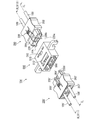
- FIG. 1 It is a figure which shows the other connection member (modification 2) used instead of the connection member of FIG. It is a perspective view which shows the optical connector apparatus by the 2nd Embodiment of this invention.
- the connectors (first connector and second connector) and adapter included in the illustrated optical connector device are separated from each other.
- the illustrated optical connector device is in a connected state.
- FIG. 26 is a cross-sectional view showing the adapter taken along line XXX--XXX in FIG. 25. It is sectional drawing of an adapter at the time of applying the connection member (modification 4) of FIG. 33 to the adapter of FIG. It is a perspective view which shows the connection member contained in the adapter of FIG. It is a front view which shows the connection member of FIG. It is a partially cutaway side view showing an optical connector device according to a third embodiment of the present invention. In the figure, only the housing is shown in cross section.
- FIG. 1 It is a perspective view which shows the adapter used for the optical connector apparatus by the 4th Embodiment of this invention. Note that the adapter holds the connection member. It is a perspective view which shows the connection member currently hold
- FIG. 44 is a cross-sectional view of the adapter taken along line XLV--XLV in FIG. 43. However, illustration of the optical element is omitted. It is a perspective view which shows the optical connector apparatus by the 7th Embodiment of this invention.
- FIG. 47 is a cross-sectional view of the optical connector device of FIG. 46 taken along line XLVIII--XLVIII.
- FIG. 47 is a cross-sectional view showing the optical connector device of FIG. 46 along the line IL--ILX.
- It is a top view which shows the adapter of FIG.
- It is a front view which shows the adapter of FIG.
- It is sectional drawing which shows the adapter of FIG. 50 along the LII--LII line.
- FIG. 52 is a cross-sectional view of the adapter of FIG. 51 taken along LIII--LIII.
- FIG. 55 is a side view showing contact between the ferrule shown in FIG. 54 and a normal ferrule.
- the optical connector device includes a connector to which a photoelectric composite cable is connected, and an adapter that relays the connector and a connection object.
- the connector includes a ferrule to which the photoelectric composite cable is connected, and the adapter includes a connection member.
- the electro-optical connection between the connector and the adapter is performed by connecting the ferrule of the connector to the connection member of the adapter.
- connection object it is also possible to regard each combination of the adapter and the counterpart connector, or a combination of the adapter and the connector provided with the optical element as one connection object.
- an optical connector device compatible with an optical / electrical composite cable according to the present embodiment will be described in detail with reference to the drawings.
- the optical connector device according to the first embodiment of the present invention is intended to connect the two by causing the connection member to hold the ferrule.
- a description will be given of a first embodiment including two connectors and an adapter for relaying them.
- the optical connector device 10 includes a first connector 200 connected to the first photoelectric composite cable 100 and a second connector 200 connected to the second photoelectric composite cable 100 ′. 'And an adapter 500 that relays the connection between the first connector 200 and the second connector 200'.
- the first connector 200 includes a first ferrule 220, and the first ferrule 220 is connected to the first photoelectric composite cable 100.
- the second connector 200 ′ also includes a second ferrule 220 ′, and the second ferrule 220 ′ is connected to the first photoelectric composite cable 100 ′.
- the connection structure between the first photoelectric composite cable 100 and the first ferrule 220 is shown in FIGS.
- or 4th connection structure shown can be used suitably.
- the first connection structure includes the photoelectric composite cable 100, a ferrule 2200a made of a conductive material such as metal, and a sleeve 240 made of a conductive material such as metal. ing.
- a conductive material in addition to the metal, a conductive resin or a material in which a metal thin film is formed on the surface of an insulating resin may be used.
- the optoelectric composite cable 100 includes an optical fiber core wire 121 composed of an optical fiber strand 110 and a protective coating 120 covering the optical fiber strand 110, and Are provided with a metal conductor 130 in which a plurality of metal strands are arranged without gaps to form a pipe-like outer conductor, and a jacket 140 covering them.
- Outer jacket 140 in the present embodiment is made of polyvinyl chloride.
- the optical / electrical composite cable 100 according to the present embodiment further includes a tensile fiber 122 provided between the optical fiber core wire 121 and the metal conductor 130, as shown in FIG.
- the ferrule 2200a includes a main body part 210 and a connection part 211 located at the rear part of the main body part.
- the main body 210 has the optical fiber core 121 inserted therein and holds the inserted optical fiber core 121 at the center.
- the connection part 211 is a part that plays a role of connecting to the photoelectric composite cable 100 (in particular, the metal conductor 130).
- a holding hole having an inner diameter substantially the same as the outer diameter of the optical fiber core wire 121 is formed from the rear end of the ferrule 2200a (that is, the rear end of the connection portion 211) to the inside of the main body portion 210, and A communication hole that connects the holding hole and the tip of the ferrule 2200a (that is, the tip of the main body 210) and has a diameter substantially the same as that of the optical fiber 110 is formed in the main body 210. Yes.
- the communication hole is provided at the center of the main body 210 in the radial direction.
- the connection part 211 of the ferrule 2200a includes a cylindrical part 212 extending toward the rear end and a ring-shaped groove 232 for receiving the sleeve 240, as shown in FIG.
- the cylindrical portion 212 in the present embodiment has an inner diameter substantially equal to the outer diameter of the optical fiber core wire 121 and a thickness substantially equal to the thickness of the outer sheath 140 of the optical / electrical composite cable 100. have.
- the ring-shaped groove 232 has an L-shaped cross section that protrudes in parallel with the cylindrical portion 212 on the radially outer side of the cylindrical portion 212 and extends toward the rear end side of the ferrule 2200a.
- the largest inner diameter of the ring-shaped groove 232 in the present embodiment is substantially equal to the outer diameter of the sleeve 240.
- the ferrule 2200a and the sleeve 240 are connected to the photoelectric composite cable 100 as described above.
- the outer sheath 140 of the photoelectric composite cable 100 is removed, and the metal conductor 130 is exposed (exposed). Further, the unnecessary metal conductor 130 is removed, and the optical fiber core wire 121 is exposed (exposed). In addition, at the tip of the optical fiber core wire 121, the protective coating 120 is removed, and the optical fiber strand 110 is exposed (exposed).
- the photoelectric composite cable 100 is inserted into the sleeve 240. In other words, the sleeve 240 is located behind the exposed metal conductor 130 and on the jacket 140.
- the metal conductor 130 is once folded and then folded for the next step, and is slightly lifted from the optical fiber core wire 121.
- the length of the exposed portion (the exposed portion) of the metal conductor 130 in the axial direction is the length of the cylindrical portion 212. Is substantially equal to
- an adhesive is applied to the outer periphery of the protective coating 120 (the outer periphery of the optical fiber core wire 121), and inserted into the ferrule 2200a as shown in FIG. 5 (b).
- the optoelectric composite cable 100 optical fiber core wire 121 is bonded to the ferrule 2200a.
- the metal conductor 130 is disposed outside the cylindrical portion 212.
- the sleeve 240 is slid toward the tip of the ferrule 2200a, and as shown in FIG. 5C, the tip of the sleeve 240 is brought into contact with the ring-shaped groove 232 of the ferrule 2200a. Thereby, the sleeve 240 and the ferrule 2200a are electrically connected.
- the cylindrical portion 212 having substantially the same thickness as the outer jacket 140 is inserted inside the exposed metal conductor 130, so that the outer side and the outer side of the metal conductor 130 are outside. There is no step between the outer periphery of the cover 140. That is, the cylindrical portion 212 functions as a step eliminating portion.
- the sleeve 240 is caulked in a state where the step is eliminated by the cylindrical portion 212, thereby connecting the metal conductor 130 and the ferrule 2200a.
- the sleeve 240 in the present embodiment functions as a caulking portion. After the sleeve 240 is crimped, the adhesive is dried by heating, and finally the optical fiber 110 is polished to finish the connection between the optoelectric composite cable 100 and the ferrule 2200a.
- the caulking portion As described above, in the sleeve 240 that is the caulking portion, there is no step between the outer side of the metal conductor 130 and the outer periphery of the outer sheath 140 due to the presence of the tubular portion 212. There are no unnecessary gaps inside. Since the caulking portion has a simple shape, the shape after caulking the sleeve 240 is also simple, and high connection strength can be obtained.
- connection structure shown in FIGS. 8 and 9 will be described as the second connection structure.
- the same components as those in the first connection structure described above are denoted by the same reference numerals in the drawings, and the description thereof will be omitted.
- the second connection structure is different from the first connection structure in that it does not include a sleeve. However, as will be described later, a portion having functions of a caulking portion and a step eliminating portion is provided, and in that respect, it is the same as the first connection structure.
- the ferrule 2200b also includes a main body portion 210a and a connection portion 211.
- the main body 210a has substantially the same configuration as the main body 210 (see FIG. 4) having the first connection structure.
- the connection part 211a includes a first tubular part 212a extending rearward from the main body part 210a and a second tubular part 226a extending further rearward from the first tubular part 212a.
- the first cylindrical portion 212a has a first inner diameter corresponding to the diameter from the center of the photoelectric composite cable 100 to the outside of the metal conductor 130, and the second cylindrical portion 226a is an optical / electrical composite cable. It has a second inner diameter corresponding to the diameter from the center of 100 to the outer side of the outer jacket 140 (the outer diameter of the outer jacket 140).
- the outer diameters of the first cylindrical portion 212a and the second cylindrical portion 226a are equal to each other.
- the connecting portion 211a has a cylindrical appearance that does not particularly have a step, and on the inner side, there is a step between the first tubular portion 212a and the second tubular portion 226a. ing.
- the step between the first cylindrical portion 212a and the second cylindrical portion 226a in the connection structure is the thickness of the outer jacket 140. Substantially equal to thickness.
- the outer sheath 140 of the optoelectric composite cable 100 is removed, the metal conductor 130 is exposed, the unnecessary metal conductor 130 is further removed, and the optical fiber core wire 121 is exposed,
- the protective coating 120 is removed at the tip of the optical fiber core wire 121 to expose the optical fiber 110 (see FIG. 9A).
- an adhesive is applied to the outer periphery of the protective coating 120 (the outer periphery of the optical fiber core wire 121), and inserted into the ferrule 2200b as shown in FIG. 9B.
- the optoelectric composite cable 100 (optical fiber core wire 121) is bonded to the ferrule 2200b.
- the step between the metal conductor 130 and the outer jacket 140 faces the step between the first cylindrical portion 212a and the second cylindrical portion 226a, and therefore there is no unnecessary gap or the like in the connection portion 211a.
- connection between the electric composite cable 100 and the ferrule 2200b is finished.
- connection portion 211a in the present connection structure is formed by integrally forming the caulking portion and the step eliminating portion. That is, when the connecting portion 211a is described separately in the axial direction, the first cylindrical portion 212a and the second cylindrical portion 226a are formed as described above. However, when the connecting portion 211a is described separately in the radial direction, a step is formed from the inside. It becomes a cancellation part and a caulking part. In other words, the first tubular portion 212a has both the function of the step eliminating portion and the caulking portion, and the second tubular portion 226a has only the function as the caulking portion. Since the connection portion 211a having such a structure can eliminate unnecessary gaps and the like in the connection portion 211a, the shape after the connection portion 211a is caulked becomes simple, and high connection strength can be obtained.
- connection structure shown in FIGS. 10 and 11 will be described as the third connection structure.
- the same components as those in the first connection structure described above are denoted by the same reference numerals in the drawings, and the description thereof will be omitted.
- the ferrule 2200c includes a main body portion 210b and a connection portion 211b.
- the main body 210b has substantially the same configuration as the main body 210 (see FIG. 4) having the first connection structure.
- the connection part 211b is a cylindrical thing extended back, and the internal diameter is substantially equal to the outer diameter of the jacket 140 of the photoelectric composite cable 100.
- this connection structure includes a sleeve 240b.
- the inner diameter of the sleeve 240b is substantially equal to a diameter obtained by doubling the diameter from the center of the optoelectric composite cable 100 to the outside of the metal conductor 130 (this is defined as the outer diameter of the metal conductor 130).
- the outer diameter of the sleeve 240b is substantially equal to the outer diameter of the jacket 140. That is, the thickness of the sleeve 240b is substantially equal to the thickness of the outer jacket 140.
- connection structure as shown in FIG. 11, the ferrule 2200c and the sleeve 240b described above and the photoelectric composite cable 100 are connected.
- the outer sheath 140 of the optical / electrical composite cable 100 is removed, the metal conductor 130 is exposed, the unnecessary metal conductor 130 is further removed, and the optical fiber core wire 121 is exposed,
- the protective coating 120 is removed at the tip of the optical fiber core 121 to expose the optical fiber 110 (see FIG. 11A).
- the length of the exposed portion of the metal conductor 130 (the exposed portion) in the axial direction is substantially equal to the length of the sleeve 240b.
- the photoelectric composite cable 100 is inserted into the sleeve 240b, and the metal conductor 130 is covered with the sleeve 240b.
- step difference of the metal conductor 130 and the jacket 140 is eliminated. That is, in this connection structure, the sleeve 240b functions as a step eliminating portion that eliminates the step between the metal conductor 130 and the jacket 140.
- connection part 211b in this connection structure functions as a caulking part.
- connection portion 211b that is the caulking portion
- the step between the metal conductor 130 and the outer sheath 140 is absorbed by the presence of the sleeve 240b, and thus is unnecessary inside the connection portion 211b. There are no gaps. Therefore, the shape after caulking the connection part 211b becomes simple, and high connection strength can be obtained.
- connection structure shown in FIGS. 12 and 13 will be described as the fourth connection structure.
- the same components as those in the first connection structure described above are denoted by the same reference numerals in the drawings, and the description thereof will be omitted.
- the ferrule 2200d with this connection structure includes a main body part 210c and a connection part 211c as shown in FIG.
- the main body 210c has substantially the same configuration as the main body 210 (see FIG. 4) having the first connection structure.
- the connection part 211c by this connection structure is a cylindrical thing extended back, and is the same as the connection part 211b by the 3rd connection structure mentioned above. That is, the inner diameter of the connecting portion 211 c is substantially equal to the outer diameter of the outer jacket 140 of the photoelectric composite cable 100.
- connection structure includes a sleeve 240c as shown in FIG.
- the inner diameter of the sleeve 240 c is substantially equal to the outer diameter of the optical fiber core wire 121 of the photoelectric composite cable 100, and the thickness of the sleeve 240 c is substantially equal to the thickness of the jacket 140.
- the ferrule 2200d and the sleeve 240c described above are connected to the photoelectric composite cable 100.
- the outer sheath 140 of the optical / electrical composite cable 100 is removed, the metal conductor 130 is exposed, the unnecessary metal conductor 130 is further removed, and the optical fiber core wire 121 is exposed,
- the protective coating 120 is removed at the front end of the optical fiber core wire 121 to expose the optical fiber 110 (see FIG. 13A).
- the length of the exposed portion (exposed portion) of the metal conductor 130 in the axial direction is substantially equal to the length of the sleeve 240c. be equivalent to.
- a sleeve 240 c is inserted between the optical fiber core wire 121 of the photoelectric composite cable 100 and the metal conductor 130.
- step difference of the metal conductor 130 and the jacket 140 is eliminated. That is, although the size of the sleeve 240c in the present connection structure and the sleeve 240b in the third connection structure (see FIG. 10) are different, like the sleeve 240b in the third connection structure, the sleeve 240c has the metal conductor 130 and the outer cover. It functions as a level difference elimination unit that eliminates the level difference from 140.
- connection part 211c in this connection structure functions as a caulking part.
- connection portion 211c that is the caulking portion
- the step between the metal conductor 130 and the outer sheath 140 is eliminated due to the presence of the sleeve 240c, so that it is unnecessary inside the connection portion 211c.
- connection structure As mentioned above, although the 1st thru
- the metal conductor is crushed when the cylindrical portion or the sleeve is inserted inside the metal conductor (the radial thickness of the photoelectric composite cable is reduced).
- the thickness of the cylindrical portion or the sleeve may be made slightly thicker than the thickness of the jacket in consideration of the reduction.
- the connection structure between the photoelectric composite cable and the ferrule according to the present invention, and the connection method for connecting the photoelectric composite cable and the ferrule by the connection structure are also applied to all the photoelectric composite cables using the ferrule. be able to.
- a connector for an optical / electrical composite cable can be formed with a size almost the same as a connector for a conventional optical cable. That is, when the connector according to the present embodiment is adopted, electrical wiring can be performed in a space dedicated for optical wiring in the device, and space saving of the device can be achieved.
- the optical connector device 10 will be described again with reference to FIGS. 1 to 3, 14, and 15.
- the 1st photoelectric composite cable 100 and 1st ferrule 220 (or 2nd photoelectric composite cable 100 'and 2nd ferrule 220') by this Embodiment are connected by the 1st connection structure mentioned above. Is,
- the first connector 200 includes a first connector housing 202 made of an insulating material, a first ferrule 220, a first sleeve (first caulking portion) 240, and a first urging member. 206 and a first cable stopper 207 made of an insulating material.
- the first connector housing 202 has a locking portion 204 (described later) locked to the adapter 500 and a lock releasing portion 205 for operating the locking portion 204. .
- the first ferrule 220 has an entire surface made of a conductive material (hereinafter, such a ferrule is referred to as a “metal type”). Specifically, the first ferrule 220 is made of copper as a base material and nickel-plated and gold-plated thereon. The first ferrule 220 may be made of other members, but at least the surface is required to have conductivity in order to achieve electrical connection with the first metal conductor 130. For example, after the base material is made of resin, the ferrule may be formed by metal plating on the surface thereof. However, in the present embodiment, as described above, since the caulking process is employed for connection with the photoelectric composite cable 100 (see FIG. 5), the base material of the first ferrule 220 is as described above. It is preferable that it is copper (metal). In the following,
- the first ferrule 220 includes a connected portion 221 that includes the distal end surface 225 of the first ferrule 220 and is connected and held to a connecting member 520 (described later) of the adapter 500, and more than the connected portion 221.
- a large-diameter portion 228 having a large diameter, a shoulder portion 230 having a larger diameter than the large-diameter portion 228, and a cylindrical portion (first step eliminating portion) 212 extending rearward from the shoulder portion 230 are provided.
- the first ferrule 220 is held by the first connector housing 202 so that the connected portion 221 protrudes forward from the front end surface 203 of the first connector housing 202 and is movable in the front-rear direction. Yes.
- the large-diameter portion 228 of the first ferrule 220 is slidably supported by the first connector housing 202, and the shoulder portion 230 defines a forward movement limit.
- a bevel process (chamfering process) is performed at the tip of the first ferrule 220 to form a bevel portion 223. Therefore, the diameter R 1 of the front end surface 225 of the first ferrule 220 is smaller than the outer diameter R 2 of the connected portion 221. Further, the thickness of the tubular portion 212 is substantially equal to the thickness of the first jacket 140 of the first photoelectric composite cable 100.
- the optical / electrical composite cable 100 is also applied to the first biasing member 206 formed of a coil spring. Is going through. Then, all of them are inserted into the first connector housing 202 from the rear, and then the first cable stopper 207 is assembled to the rear of the first connector housing 202, so that the pressed surface 227 of the first ferrule 220 and the first The first urging member (coil spring) 206 is accommodated in a compressed state between the cable stopper 207 and the cable stopper 207. Thereby, the 1st biasing member 206 will always press the to-be-pressed surface 227 of the 1st ferrule 220 ahead.
- the first biasing member 206 is as shown in FIG.
- the first ferrule 220 of the first connector 200 is always urged toward the second ferrule 220 '(described later) of the second connector 200'.
- the first biasing member 206 and the first cable stopper 207 do not contribute to the electrical connection between the first metal conductor 130 and the first ferrule 220 as described above. Therefore, as described above, the first cable stopper 207 can be made of an insulating material, and the first biasing member 206 can be made of an insulating member such as a low-cost resin. .
- the second connector 200 ′ includes a second connector housing 202 ′ made of an insulating material, a second ferrule 220 ′, and a second sleeve (second caulking portion) 240 ′. And a second urging member 206 ′ and a second cable stopper 207 ′ made of an insulating material.
- Each component of the second connector 200 ′ has the same structure and the like as each component of the first connector 200.
- the second connector housing 202 ′ operates a locking portion 204 ′ (described later) locked to the adapter 500 and a locking portion 204 ′ as shown in FIG. And a lock release unit 205 ′. Further, as shown in FIG.
- the second ferrule 220 ′ is provided with a second cylindrical portion 212 ′, and the second cylindrical portion 212 ′ functions as a second caulking portion.
- the sleeve 240 ′ functions as a second step eliminating portion that eliminates the step between the second metal conductor 130 ′ and the second jacket 140 ′.
- the adapter 500 includes an adapter housing 510 made of an insulating material, a connection member 520 made of a conductive material, and a housing portion made up of a first part 530 and a second part 540 that hold the connection member 520. 550.
- the adapter housing 510 has a locking hole 512 for locking the locking portion 204 of the first connector 200 and a locking for locking the locking portion 204 ′ of the second connector 200 ′.
- a hole 512 ′ is formed.
- the connecting member 520 holds the first ferrule 220 and the second ferrule 220 ′ and is used for electrical connection between the first ferrule 220 and the second ferrule 220 ′.
- the illustrated connecting member 520 is a so-called split sleeve having a cylindrical tube with a slit parallel to the axis.
- the first ferrule 220 and the second ferrule 220 ′ are not inserted into the connecting member 520 in order to ensure the electrical connection between the first ferrule 220 and the second ferrule 220 ′.
- the inner diameter of the connecting member 520 in the state is such that the connected portion 221 of the first ferrule 220 or the connected portion of the second ferrule 220 ′ (the connected portion of the first ferrule 220). 221 is set smaller than the outer diameter R 2 (see FIG. 15).
- the connection member 520 is connected to the first ferrule 220.
- the connected portion 221 and the connected portion of the second ferrule 220 ′ are gripped from the outside.
- the connecting member 520 when used instead of a simple connecting member, the first ferrule 220 and the second ferrule 220 ′ can be actively connected to each other. Accordingly, when the first photoelectric composite cable 100 and the second photoelectric composite cable 100 ′ are connected to the first ferrule 220 and the second ferrule 220 ′, the tips of the ferrule 220 and the second ferrule 220 ′ are polished. Thus, even when a good electrical connection cannot be achieved between the tips of the ferrule 220 and the second ferrule 220 ′, the electrical connection between the first ferrule 220 and the second ferrule 220 ′ can be achieved. it can.
- the inner diameter of the connecting member 520 in the present embodiment is larger than the diameter R 1 (see FIG. 15) of the tip surfaces of the first ferrule 220 and the second ferrule 220 ′. Accordingly, when the first ferrule 220 and the second ferrule 220 ′ are inserted into the connecting member 520, the bevel portion 223 of the first ferrule 220 or the bevel portion of the second ferrule 220 ′ (the bevel portion 223 of the first ferrule 220). And the same ferrule 220) serve to widen the inner diameter of the connection member 520, so that the first ferrule 220 and the second ferrule 220 ′ can be smoothly inserted into the connection member 520.
- connection member 520 is made of a conductive material.
- the surface of the resin connection member may be plated with metal.
- the connection member 520 itself is made of a conductive material as in the present embodiment.
- the accommodating portion 550 is composed of two parts, a first part 530 and a second part 540, and the inner diameter of the connection member 520 is variable.
- the connection member 520 is held in a state.
- the housing portion 550 includes a housing portion 552 that houses the connection member 520, and a first insertion port 532 and a second insertion port 542 that communicate with the housing space 554.
- the accommodating space 554 has a space larger than the outer diameter of the connecting member 520 even when the connected portion 221 of the first ferrule 220 and the connected portion of the second ferrule 220 ′ are inserted into the connecting member 520.
- the connecting member 520 can have its inner diameter variable when connected to the connected portion 221 of the first ferrule 220 or the connected portion of the second ferrule 220 ′.
- the connected portion 221 of the first ferrule 220 and the connected portion of the second ferrule 220 ' are inserted, respectively.
- the inner diameters of the first insertion port 532 and the second insertion port 542 are larger than the inner diameter of the connection member 520 in the normal state, but smaller than the outer diameter of the connection member 520 in the normal state. Therefore, the connection member 520 does not come out of the housing part 550 after the housing part 550 is configured by combining the first part 530 and the second part 540.
- the housing part 550 is configured by combining the first part 530 and the second part 540 so as to enclose the connection member 520, and then the housing part 550 is held in the adapter housing 510.
- the adapter 500 is configured by fixing.
- the optical connector device since the first ferrule 220 and the second ferrule 220 ′ are held by the conductive connecting member 520, the first ferrule 220 and The electrical connection with the second ferrule 220 ′ can be ensured.
- the case where the tip of the first ferrule 220 and the tip of the second ferrule 220 ′ are polished has been described.
- the gap between the tip of the first ferrule 220 and the tip of the second ferrule 220 ′ is described. Needless to say, the present invention can be applied even when good electrical connection is achieved.
- each of the first ferrule 220 and the second ferrule 220 ′ described above is supposed to have conductivity at least over the entire surface.
- the first ferrule 220a has the first ferrule 220a. It is also possible to prevent an unintended short circuit at the tip of the first ferrule 220a by partially making the end including the tip surface 225a an insulator (hereinafter, such a ferrule is referred to as “composite type”).
- the illustrated first ferrule 220 a also has a substantially cylindrical large diameter having an outer diameter larger than the outer diameter of the connected portion 221 and the connected portion 221. Part 228.
- the held portion according to the present embodiment includes a front portion 222 made of an insulator and a rear portion 224 formed integrally with the large diameter portion 228 and made of a conductor.
- the front portion 222 is formed with a hole 229 for holding an optical fiber at the center, and a portion having an outer diameter smaller than that of the front portion 222 is formed on the rear side. I have.
- the outer diameter of the front part 222 is formed to be substantially equal to the outer diameter of the rear part 224.
- the rear part is made of copper as a base material and nickel plated and gold plated thereon.
- the rear part 224 and the large diameter part 228 are electrically connected to the first metal conductor 130 of the first photoelectric composite cable 100.
- the first ferrule 220a and the first photoelectric composite cable 100 according to the present embodiment are connected by the above-described second connection structure (FIGS.
- the connection structure to be used is not limited to this.
- the rear portion 224 of the first ferrule 220a may be made of another member, but at least the surface needs to be conductive in order to achieve electrical connection with the first metal conductor 130. Is done.
- the first ferrule 220a may be configured by forming the base material from a resin and then performing metal plating on the surface thereof.
- the rear portion 224 and the large-diameter portion 228 may be integrally formed with a resin, and the respective surfaces may be formed by metal plating.
- the base material of the first ferrule 220a is copper (metal) as described above. Is preferred.
- the first ferrule 220a is formed by combining a member including the front portion 222 (front side member) with a member including the rear portion 224 and the large diameter portion 228 (rear side member). Specifically, as shown in FIG. 16, the rear member has a cavity for receiving the front member therein. The first ferrule 220a is formed by inserting the front member into the cavity.
- the above-described adapter 500 can of course be applied to the optical connector device.
- the adapter 500a as shown in FIG. 18 is applied. More preferably. Similar to the adapter 500 described above, the adapter 500a includes an adapter housing 510a made of an insulator and a connection member 520b made of a conductor held by the adapter housing 510a (the connection member 520b will be described later).
- the first connector 200 and the first connector 200 are the same as the first ferrule 220a (see FIGS. 16 and 17) described above. It has.
- the adapter housing 510a includes a substantially cylindrical accommodating portion 550a for accommodating the connecting member 520a and a protrusion 505.
- the housing portion 550a does not include the first portion 530 and the second portion 540 like the adapter housing 510 (see FIG. 14) described above, and is integrally formed without a seam.
- the protrusion 505 prevents a finger or the like from accidentally entering the adapter housing 510a when the adapter 500a is handled.
- the length of the protrusion 505 from the inner surface of the adapter housing 510a is longer than the length of the accommodating portion 550a.
- a connecting member 520a as shown in FIG. 20 is accommodated in the accommodating portion 550a.
- the connecting member 520a includes a receiving portion 527 provided at both ends in the longitudinal direction, and two spring portions 528 formed by making incisions 526 at three locations along the longitudinal direction from the edge portion 541 of the receiving portion 527. And a press-fitting portion 551.
- the receiving portion 527 is for receiving the connected portion 221 of the first ferrule 220a (or the connected portion 221 of the second ferrule 220a ') along a predetermined direction (insertion / extraction direction). Since the connection member 520a is provided with a spring portion 528 having a relatively low elastic coefficient, a slight gripping force is applied.
- connection member 520a when the first ferrule 220a is inserted into the connection member 520a, the connection member 520a is elastically deformed so that its diameter increases. Thereby, even if there is some variation in the size of the first ferrule 220a and the connecting member 520a, it can be dealt with. Further, since the rear portion 224 of the first ferrule 220a inserted into the connection member 520a is electrically connected at three locations of the two spring portions 528 and the receiving portion 527 of the connection member 520a, the first ferrule 220a The contact reliability with the connecting member 520a can be improved.
- connection member 520a is press-fitted into the accommodating portion 550a of the adapter housing 510a and the press-fitting portion 551 is locked to the inner wall of the accommodating portion 550a.
- the connecting member 520a is accommodated in the accommodating portion 550a.
- each of the first connector 200a and the second connector 200'a may be connected to the adapter 500a.
- connection member 520a may be held by the adapter 500 (see FIG. 14) in the same manner as the connection member 520 described above. In this case, the connection member 520a is press-fitted into the first part 530 and the second part 540 of the adapter 500 and the press-fitting portion 551 is locked to the inner walls of the first part 530 and the second part 540, whereby the connection member 520a is Retained.
- the width of the connecting member 520b is specified as shown in FIG. 21, as shown in FIG. A member formed by forming an H-shaped cut (groove) 526 so as to be orthogonal to the slit 523 may be used as the connecting member.
- the holding function of the connection member may be an auxiliary function, and the main function of the connection member may be an electrical connection function between the ferrules, while the axis alignment between the ferrules may be secured by a member or the like that is provided separately.
- an optical connector device 10b shown in FIGS. 22 to 30 can be cited.
- the configuration other than the first ferrule 220a and the connection member 520c is the same as that of the optical connector device 10 (see FIG. 1) described above. Accordingly, the same members are denoted by the same reference numerals, and the description thereof is omitted.
- the optical connector device 10b includes a first connector 200 connected to the first photoelectric composite cable 100 and a second connector 200 connected to the first photoelectric composite cable 100 ′. And an adapter 500 that relays the first connector 200 and the second connector 200 ′.
- the first ferrule 220b is a composite type ferrule similar to the first ferrule 220a (see FIGS. 16 and 17) described above, and has substantially the same structure as the first ferrule 220a. ing. That is, the first ferrule 220b includes a held portion 221 including a front portion 222 made of a conductive material and a rear portion 224 made of an insulating material, a large diameter portion 228, a shoulder portion 230, and a first tube. The shape part 212 is provided.
- the connection structure of the first ferrule 220b is different from the first ferrule 220a described above, and the first ferrule 220b has the first connection structure shown in FIGS.
- the first ferrule 220b is attached to the first connector housing 202 so that the front portion 222 of the held portion 221 protrudes further forward from the front end surface of the first connector housing 202 and is movable in the front-rear direction. Is retained.
- the large-diameter portion 228 is slidably supported by the first connector housing 202, and the shoulder portion 230 defines a forward movement limit.
- the first ferrule 220b inserted from the rear into the first connector housing 202 is always pressed forward by the first biasing member 206.
- the first biasing member 206 may be formed of an insulating member such as a low-cost resin.
- the second ferrule 220b ′ also has a connected portion 221 ′ composed of a front portion 222 ′ and a rear portion 224 ′, a large-diameter portion 228 ′, and a shoulder, like the first ferrule 220b.
- a portion 230 ′ and a second tubular portion 212 ′ are provided.
- the adapter 500 has substantially the same configuration as the adapter 500 (see FIGS. 1 to 3) described in the first embodiment, but the connection member 520c (sleeve) held is different. That is, as shown in FIG. 24, the adapter 500 includes an adapter housing 510 made of an insulating material, a connection member 520c made of a conductive material, and a housing portion 550 that holds the connection member 520c.
- the housing portion 550 also has a first portion 530 and a second portion, similarly to the adapter 500 (see FIG. 14) described in the first embodiment. It consists of two parts with 540.
- the accommodating portion 550 includes an accommodating space 554 that accommodates the connection member 520 c and insertion ports 532 and 542 that communicate with the accommodating space 554.
- the inner diameters of the insertion ports 532 and 542 are smaller than the inner diameter (the diameter of the inner wall portion) of the accommodation space 554. More specifically, the accommodation space 554 can accommodate the connection member 520 c, whereas the insertion ports 532 and 542 are configured so that the connection member does not come out of the accommodation space 554.
- the first portion 530 and the second portion 540 are combined to form the accommodating portion 550 so as to include the connection member 520 c, Thereafter, the adapter 500 is configured by holding and fixing the accommodating portion 550 in the adapter housing 510 using the fixing portion 560.
- the connecting member 520c also holds the first ferrule 220b and the second ferrule 220b ′, and the first ferrule 220b and the second ferrule 220b ′. This is for the purpose of electrical connection.
- the connecting member 520c includes the front portion 222 provided on the connected portion 221 of the first ferrule 220b and the second ferrule 220b ′.
- the front portion 222 ′ provided on the connected portion 221 ′ is gripped from the outside, thereby achieving electrical connection between them.
- the connecting member 520c presses a single metal flat plate having two edges so that the edges face each other.
- the cylindrical main body 522 is formed.
- the edge facing portion (matching portion) 524 formed by facing the edges is configured to substantially match the edges, and thus the main body portion 522 is configured as described above. It is cylindrical.
- the present invention is not limited to this.
- the edge facing portion 524 may be configured by facing the edges in a state where the edges are slightly separated from each other. In that case, the main body portion 522 has a substantially cylindrical shape.
- the whole connecting member 520c is the main body portion 522.
- the front end and the rear end are provided with shape characteristics. Even in this case, in order to ensure an appropriate ferrule holding function, it is necessary to provide a portion recognized as the main body 522 in a part of the connection member 520c.
- the main body 522 includes three ferrule abutting portions 525a, 525b, and 525c that abut against the first ferrule 220b and the second ferrule 220b ′ when the connecting member 520c holds the first ferrule 220b and the second ferrule 220b ′. ing. These ferrule contact portions 525a, 525b, and 525c are formed apart from each other in a plane (orthogonal plane) orthogonal to the axial direction of the connection member 520c. Specifically, the ferrule contact part 525a is located on the opposite side of the edge facing part 524 in the orthogonal plane.
- the ferrule abutting portions 525b and 525c are arranged so that the central angle at the center between the ferrule abutting portion 525a and the connecting member 520c is approximately 120 degrees. That is, the illustrated ferrule contact portions 525a, 525b, and 525c are arranged at intervals of approximately 120 degrees in the orthogonal plane.
- the ferrule contact portions 525a, 525b, and 525c are linear in the orthogonal plane, and extend along the axial direction of the connection member 520c. That is, each ferrule contact part 525a, 525b, 525c has an elongated flat plate shape.
- the connection member 520c has a shape like a triangular rice ball (a triangular shape with rounded vertices) in the orthogonal plane.
- the difference between the inscribed circle and the circumscribed circle shown in FIG. 29 can be made larger than the thickness of the connecting member 520c itself. That is, the inscribed circle can be adjusted to make the ferrule holding function appropriate, while the circumscribed circle can be adjusted to prevent the connection member 520c from rattling in the accommodation space 554 of the accommodation portion 550. And in the case of the connection member 520c of this Embodiment, this adjustment can be performed at the time of the press work of a metal flat plate, or can be performed by subsequent press work. Therefore, according to the present embodiment, the circumscribed circle and the inscribed circle of the connecting member 520c can be easily adjusted by low-cost pressing, thereby appropriately holding the ferrule and preventing rattling in the accommodating portion 550. Both can be achieved.
- connection member 520d shown in FIGS. 31 to 33 may be configured to be more suitable for connection of the photoelectric composite cable.
- the connecting member 520d is also formed by pressing one metal flat plate having two edges and having the cylindrical main body 522d facing each other. For this reason, the connecting member 520d also has an edge facing portion 524 in which the edges face each other.
- the ferrule abutting portions 525a, 525b, and 525c arranged in the same manner as the ferrule 520c (see FIG. 29) are also provided in the main body portion 522d of the connecting member 520d by pressing.
- the ferrule contact portion 525a is located on the opposite side of the edge facing portion 524 in the orthogonal plane, and the ferrule contact portions 525b and 525c are center angles at the centers of the ferrule contact portion 525a and the connecting member 520d. Are arranged so as to form approximately 120 degrees. In other words, the ferrule contact portions 525a, 525b, and 525c shown in the figure are arranged at intervals of approximately 120 degrees in the orthogonal plane.
- the connecting member 520d is not obtained by pressing a metal flat plate having a simple structure, but is formed by punching the front end and the rear end portion into a predetermined shape, and bending the front end.
- Each of the rear ends has a pair of spring portions 528d and a support portion 529.
- the spring portion 528d is provided corresponding to the two ferrule abutting portions 525b and 525c located at the same distance from the edge facing portion 524 across the edge facing portion 524. Therefore, the spring portion 528d is a rear portion 224 provided in the connected portion 221 of the first ferrule 220b shown in FIG. 24 (or a rear portion 224 ′ provided in the connected portion 221 ′ of the second ferrule 220b ′).
- the support portion 529 is provided corresponding to the edge facing portion 524. That is, the support portion 529 is located in the middle of the two spring portions 528d in the orthogonal plane. As shown in FIG. 31, the support portion 529 is a portion provided to reduce a gap between the inner wall of the accommodation space 554 of the accommodation portion 550 and the outer surface of the connection member 520d.
- the connection member 520d is accommodated in the accommodation space 554 of the connection member 550 with a backlash.
- the first ferrule 220b (or the second ferrule 220b ′) is provided when the support portion 529 is not provided. There is a possibility that a vertical displacement occurs in the accommodation space 554. In this case, when the first ferrule 220b (or the second ferrule 220b ′) is inserted into the connecting member 520d, the first ferrule 220b (or the second ferrule 220b ′) hits the end surface of the connecting member 520d, or cannot be inserted, or invitation may be insufficient.
- the gap between the accommodation space 554 of the accommodation portion 550 and the outer surface of the connection member 520d that is, the backlash in the vertical direction that becomes a problem because the backlash is reduced can be eliminated.
- the support portion 529 may or may not have elasticity, the support portion 529 may contact the inner wall of the housing portion 550 from the beginning, or the first ferrule 220b (or The second ferrule 220b ′) may be configured to contact when inserted into the connecting member 520d.
- the first to fourth connection structures are the two types of adapter housing structures.
- the adapter housing 510 see FIG. 14 or FIG. 27, FIG. 19
- 510a see FIG. 19
- connection member structures there are five types of connection member structures: a connection member 520 (see FIG. 2), a connection member 520a (see FIG. 20) Regarding the member 520b (see FIG. 21), the connecting member 520c (see FIG. 28), and the connecting member 520d (see FIG. 32), the metal ferrule 220 (see FIG. 3) and the composite type of two types of ferrules are used.
- the optical connector device according to the present embodiment has been described above. Not limited only to the embodiment, by appropriately selecting the optimum one of these, we are also possible to configure the optical connector device by combining them.
- optical connector device by embodiment mentioned above was provided with three components of two connectors (1st connector 200 and 2nd connector 200 ') and an adapter, this invention is restrict
- the concept of the present invention can be applied to any optical connector device having a connection member that holds two ferrules in a state of abutting each other.
- the optoelectric composite connector is connected to another optoelectric composite connector through an adapter.
- the target to be connected through the adapter is a photodiode or the like. It is good also as an optical element.
- the optical connector device holds a ferrule 220 connected to the photoelectric composite cable 100, an optical element 800 such as a photodiode, and the optical element 800. And a housing 810.
- the photoelectric composite cable 100 has the same configuration as the photoelectric composite cable in the first embodiment, and the ferrule 220 is of the metal type (see FIG. 3) in the first embodiment. Is used. Therefore, the ferrule 220 in the present embodiment also includes a connected portion 221, a large diameter portion 228, a shoulder portion 230, and a cylindrical portion (not shown) that functions as a step eliminating portion.
- the photoelectric composite cable 100 is attached to the ferrule 220 by caulking the sleeve 240 that functions as a caulking portion.
- a biasing member (coil spring) 206 that is arranged so as to constantly press the pressed portion 227 of the ferrule 220 and biases the ferrule 220 toward the optical element 800 is also provided. Is provided.
- the ferrule 220, the sleeve 140, and the biasing member 206 can be accommodated in a space constituted by an insulating connector housing and a cable stopper, as in the first embodiment (see FIG. 3).
- the optical element 800 is mounted on a substrate (not shown) and includes a terminal 801 connected to a conductive pattern (not shown) of the substrate.
- the housing 810 in this embodiment is made of a conductive material and includes a mounting surface 802 that is mounted on a substrate.
- the housing 810 is formed with a cylindrical connection portion 820 extending toward the ferrule 220 side.
- the connected portion 221 of the ferrule 220 is inserted into the connecting portion 820, whereby the contact surface 233 that forms the boundary between the connected portion 221 and the large diameter portion 228 of the ferrule 220 and faces the front is connected to the connecting portion 820.
- the ferrule 220 and the housing 810 can be electrically connected to each other by being brought into contact with the joint end surface 812 which is the end surface of the first end.
- the contact surface 233 of the ferrule 220 is abutted against the joining end surface 812 of the housing 810, the distance between the optical element 800 and the front end surface 225 of the ferrule 220 can be made constant and held by the ferrule 220.
- the optical coupling between the optical fiber and the optical element 800 can also be stabilized.
- the entire housing 810 is made of a conductive material.
- a part of the housing is subjected to metal plating or the like so as to be partially conductive. It may be an electrical path to the substrate.
- the optical element is held in the housing.
- the optical element may be held in an adapter 900 as shown in FIG.
- an optical connector device including an connector that holds an optical element and relays the connection between the mating connector and the optical element and a connector
- the 1st connector 200 (refer FIG. 1) by 1st Embodiment mentioned above can be used, for example.
- the ferrule held by the first connector 200 the ferrule 220 (see FIG. 14), the ferrule 220a (see FIG. 10), and the ferrule 220b (see FIG. 12) can be used. Description of the details of the connector and the ferrule will be omitted, and only the adapter and the connection member held by the adapter will be described.
- the adapter 900 includes an insulating housing 910 and a connecting member 930 made of a conductor held by the housing 910.
- the housing 910 includes a substantially cylindrical accommodating portion 950 for accommodating the connection member 930 and an element accommodating portion 960 for accommodating an optical element (not shown). Have.
- the optical element is held in the element housing portion 960 so as to face the end face of the optical fiber held by the connector ferrule.
- connection member 930 generally has a structure in which the connection member 520a shown in FIG. 20 is halved. Specifically, the connection member 930 is formed by adding a connection extending portion 970 extending in the radial direction to a substantially cylindrical portion, and specifically, receives the ferrule of the connector along a predetermined direction. Receiving portion 927, two spring portions 928 formed by making cuts 926 at three locations along the longitudinal direction from the end portion 941 of the receiving portion 927, and the connection extending portion 970 described above. Yes. As is apparent from FIG. 36, the connection extension 970 is provided at the end opposite to the end 941 in which the above-described cut 926 is inserted, and the adapter 900 in FIG.
- connection member 930 When it is mounted, it is electrically connected to the circuit pattern on the substrate. Similar to the connection member 520a shown in FIG. 20, the connection member 930 is provided with a slight gripping force because the spring portion 928 having a relatively low elastic coefficient is provided. With this structure, for example, when the ferrule 220 (see FIGS. 1 to 3) is inserted into the connection member 930, for example, the connection member 930 is elastically deformed so that its diameter increases. As a result, even if there is some variation in the size of the ferrule 220 or the connecting member 930, it can be dealt with. Note that even when a composite type ferrule 220a (or ferrule 220b: see FIG. 24) as shown in FIG.
- connection member 930 the rear portion 224 (or rear portion 224) of the ferrule 220a inserted into the connection member 930 is used. ') Is electrically connected at three locations of the two spring portions 928 and the receiving portion 927 of the connecting member 930. Therefore, in any ferrule, the contact reliability with the connection member 930 can be improved.
- the connecting member 930 is accommodated in the accommodating portion 950 by press-fitting the connecting member 930 into the accommodating portion 950 in the same manner as the connecting member 520a (see FIG. 20) according to the first embodiment. This is done by locking the press-fit portion 951 to the inner wall.
- the optical connector device includes a first connector 200 connected to the first photoelectric composite cable 100 and a second photoelectric composite cable 100 ′. And a second connector 200 ′ connected to the adapter and an adapter 500a that relays the connection between the first connector 200 and the second connector 200 ′.
- the optical connector device 10c is the same as the above-described optical connector device 10a (see FIG. 19) except for the connection member 520e and the first ferrule 220c. is there. Accordingly, the same reference numerals are assigned to the same members, and descriptions thereof are omitted.
- the first ferrule 220c includes a connected portion 221 made of only an insulator and a large-diameter portion 228 made of a conductor (hereinafter, such a ferrule is referred to as “ Called "insulation type”).
- the connected portion 221 is a columnar insulator in which a hole 229 for holding an optical fiber is formed at the center, and is inserted into the large diameter portion 228 so that the tip of the first ferrule 220c Is configured.
- the large diameter portion 228 is formed as a substantially cylindrical tip portion of a conductor member electrically connected to the first metal conductor 130 of the photoelectric composite cable. Further, the edge of the large diameter portion 228, that is, the boundary portion between the large diameter portion 228 and the connected portion 221 constitutes an annular contact surface 233.
- the adapter 500a includes an adapter housing 510a made of an insulator and a connecting member 520e made of a conductor held by the adapter housing 510a.
- the adapter housing 510a includes a substantially cylindrical accommodating portion 550a for accommodating the connecting member 520e, and a protrusion 505.
- the protrusion 505 prevents a finger or the like from accidentally entering the adapter housing 510a when the adapter 500a is handled.
- the length of the protrusion 505 from the inner surface of the adapter housing 510a is longer than the length of the accommodating portion 550a.
- the connecting member 520e is made of a conductor and has a substantially cylindrical shape.
- the connection member 520e has a receiving portion 527 for receiving the end portion of the first ferrule 220c (or the second ferrule 220c ′) at both ends along a predetermined direction (insertion / extraction direction), and a support portion 552 extending in the predetermined direction.
- a spring portion 528e extending from the support portion 552 in the circumferential direction of the connection member 520e, a conductive portion 541e provided at the tip of the spring portion 528e, and a press-fit portion 551.
- each spring part 528e In addition, in the free end side end part of each spring part 528e, the notch part 521 cut
- the conductive portion 541e according to the present embodiment is supported by the spring portion 528e so that it can be displaced along a predetermined direction.
- the end portion 554a of the support portion 552 and the end portion 554b of the receiving portion 527 are located at the same position in the insertion / extraction direction.
- the conductive portion 541e is positioned on the ferrule side in the insertion / extraction direction with respect to the end portions 554a and 554b, and is supported by the spring portion 528e so as to be displaceable along a predetermined direction. .
- the connecting member 520e is accommodated in the accommodating portion 550a of the adapter housing 510a described above. That is, the connecting member 520e is press-fitted into the housing portion 550a, and the press-fit portion 551 is locked to the inner wall of the housing portion 550a, so that the conductive portion 541e of the connecting member 520e protrudes from the end portion 502a of the housing portion 550a. And accommodate.
- the contact surface 233 of the first ferrule 220c of the first connector 200 contacts the conductive portion 541e of the connection member 520e. To do.
- the conductive portion 541e is displaced while sliding on the contact surface 233 of the first ferrule 220c.
- the connected portion 221 is inserted into the connecting member 520e until the contact surface 233 contacts the end portions 554a, 554b of the connecting member 520e, and the connection between the first ferrule 220c and the connecting member 520e is completed.
- the conductive portion 541e of the connection member 520e according to the present embodiment is supported by the spring portion 528e, the conductive portion 541e comes into contact with the contact surface 233 reliably by the restoring force of the spring portion 528e.
- the contact surface 233 is in contact with each of the end portions 554a and 554b, the reliability of electrical connection between the adapter 500a and the first connector 200 can be improved.
- the part including the end face of the first ferrule 220c in the present embodiment is insulative, the unintended electrical short circuit at the tip of the first ferrule 220c is prevented as in the above-described composite type ferrule. Can do.
- the ferrule held by the connector abuts on the connection object, so that an electrical and optical connection between the connector and the connection object can be achieved.
- the members constituting the connection target can be regarded as a combination of the second connector 200 'and the adapter 500a.
- the object to be connected is not only a combination of a connector and an adapter, but also an optical element such as a photodiode is accommodated in a housing or the like. It may be.
- an optical connector device according to the fifth embodiment of the present invention will be described below that includes a connection object having an optical element.
- the connector connected with a connection target object can use the thing (refer FIG. 39 and FIG. 40) provided with the insulation type ferrule 220c similarly to 4th Embodiment mentioned above, it is the connector's connection. Details are omitted here.
- a connection object 900a includes an insulating housing 910a, a connection member 930a made of a conductor held by the housing 910a, and an optical element (not shown). It has.
- the housing 910a includes a substantially cylindrical accommodating portion 950a for accommodating the connecting member 930a, and an element accommodating portion 960 for accommodating an optical element (not shown).
- the optical element is held by the housing 910a so as to face the end face of the optical fiber held by the ferrule when the ferrule is inserted into the connection object 900a.
- connection member 930a is roughly provided with a structure in which the connection member 520e shown in FIG. 42 is halved. Specifically, the connection member 930a is obtained by adding a connection extension portion 970 extending in the radial direction to a substantially cylindrical portion. Specifically, a receiving portion 927a for receiving the ferrule of the connector along a predetermined direction, a support portion 952 extending in the predetermined direction, and a spring portion extending from the support portion 952 in the circumferential direction of the substantially cylindrical portion of the connection member 930a. 928a, a conductive portion 941a provided at the tip of the spring portion 928a, and the aforementioned connection extending portion 970.
- the conductive portion 941a according to the present embodiment also has the end portion 954a of the support portion 952 and the end portion 954b of the receiving portion 927a at the same position in the insertion / extraction direction. It is formed to be located. Further, the conductive portion 941a according to the present embodiment protrudes toward the ferrule side in the insertion / extraction direction from the ends 954a and 954b, and is supported by the spring portion 928a so as to be displaceable along a predetermined direction. As is clear from FIG. 44, the connection extension 970 is provided at the end opposite to the end where the conductive portion 941a is provided, and the connection object 900a is attached to the substrate (not shown). When mounted on the circuit board, it is electrically connected to the circuit pattern on the substrate.
- the way the connecting member 930a is accommodated in the accommodating portion 950a is the same as that of the adapter 900a (see FIG. 35) of the optical connector device according to the third embodiment. That is, the connecting member 930a is press-fitted into the housing portion 950a and the press-fitting portion 951 is locked to the inner wall of the housing portion 950a, so that the conductive portion 941a of the connecting member 930a protrudes from the end portion of the housing portion 950a.
- the connecting member 930a is accommodated in the accommodating portion 950a.
- connection target 900a having the above-described configuration
- the contact surface 233 of the ferrule 220c is first formed.
- the ferrule 220c is further inserted, and the conductive portion 941a is displaced while sliding on the contact surface 233.
- the connection between the ferrule 220c and the connection object 900a is completed by inserting the connected portion 221 into the connecting member 930a until it abuts against the end portions 954a and 954b of the connecting member 930a. Thereby, it is possible to achieve an electrical connection between the connector and the connection object 900a and an optical connection.
- the conductive portion 941a is reliably in contact with the contact surface 233 of the ferrule 220c by the restoring force of the spring portion 928a.
- the contact surface 233 is in contact with each of the end portions 954a and 954b, the reliability of electrical connection between the connection object 900a and the photoelectric composite connector can be improved.
- the ferrules held by one connector are the same.
- the two ferrules included in one connector are electrically connected to the connection member at the same timing.
- the optical connector device 10d according to the present embodiment is for shifting the timing of electrical connection with the connection member between at least two ferrules when the connector is connected to the connection member. .
- the optical connector device 10d includes a first connector 200 and a second connector 200 ′ connected to the first photoelectric composite cable 100 and the second photoelectric composite cable 100 ′. And an adapter 500 that relays the connection between the first connector 200 and the second connector 200 ′.
- the first connector 200, the second connector 200 ′, the adapter 500, the first ferrule 220, the first ferrule 220b, and the connection member 520d described below are the same as those already described. Used. Therefore, these members are denoted by the same reference numerals, and description thereof is omitted.
- first ferrule refers to the two ferrules included in the first connector
- second ferrule refers to the two ferrules included in the second connector.
- the two ferrules of one connector (the first connector and the second connector) will be referred to as “first ferrule” and “second ferrule”. In other words, the first ferrule and the second ferrule are held by the same connector.
- the first connector 200 includes a first connector housing 202 made of an insulating material, a first ferrule 220 and a second ferrule 220b, and a first sleeve (first caulking portion). 240, a first urging member 206, and a first cable stopper 207 made of an insulating material.
- the first connector 200 includes a metal type first ferrule 220 and a composite type second ferrule 220b.
- the first ferrule 220 has a connected portion 221, a large diameter portion 228, a shoulder portion 230, and a tubular portion 212.
- both the connected portion 221 and the large diameter portion 228 of the first ferrule are made of a conductor.
- the connected part 221 of the first ferrule functions as a first conductive part.
- the second ferrule 220 b also has a connected portion 221, a large diameter portion 228, a shoulder portion 230, and a tubular portion 212.
- the held part 221 of the second ferrule 220b includes a front part 222 made of an insulator and a rear part 224 made of a conductor and integrally formed with the large diameter part.
- the rear part 224 functions as a second conductive part.
- the first ferrule 220 functions as the first conductive portion itself
- the first tip surface 225 and the first conductive portion which are the end surfaces of the first ferrule 220 are used.
- the distance to is zero.
- the second end surface 225a which is the end surface of the second ferrule 220b, is separated from the second conductive portion (rear portion 224) by the front portion 222 made of an insulating material. That is, the distance between the first tip surface 225 and the first conductive portion (first ferrule 220 itself) is different from the distance between the second tip surface 225a and the second conductive portion (rear portion 224).
- the first ferrule 220 and the first photoelectric composite cable 100 are connected by the above-described first connection structure (see FIGS. 4 and 5).
- the first ferrule 220 always presses the first ferrule 220 and the second ferrule 220b forward by the first biasing member 206.
- the first biasing member 206 may be formed of an insulating member such as a low-cost resin.
- the second connector 200 ′ is configured to have a mirror image relationship with the first connector 200. Further, the arrangement of the first second ferrule 220 ′ and the second ferrule 220b ′ is the same as that of the first connector 200 except that the arrangement of the first ferrule 220 ′ and the second ferrule 220b ′ is opposite to that of the first connector 200. ing. That is, as shown in FIGS.
- the second connector 200 ′ also includes a second connector housing 202 ′ made of an insulating material, a first ferrule 220 ′ and a second ferrule 220b ′, and a second sleeve ( (Second caulking portion) 240 ′, a second urging member 206 ′, and a second cable stopper 207 ′ made of an insulating material.
- the first ferrule 220 ′ of the second connector 200 ′ is a composite type ferrule (see FIG. 24), and the second ferrule 220b ′ is a metal type.
- the ferrule see FIG. 3
- the distance from the front end surface of the first ferrule 220 ′ to the first conductive portion (rear portion 224 ′) and the distance from the front end surface of the second ferrule 220b ′ to the second conductive portion (second ferrule 220b ′ itself) are They are different from each other.
- the adapter 500 includes an adapter housing 510 made of an insulating material and two connection members 520d made of a conductive material (FIG. 32). And a housing portion 550 that houses the connecting member 520d.
- the adapter housing 510 has a locking hole 512 for locking the locking portion 204 of the first connector 200 and a locking for locking the locking portion 204 ′ of the second connector 200 ′.
- a hole 512 ′ and an accommodating portion 550 are formed.
- the accommodating portion 550 includes two parts, a first part 530 and a second part 540.
- the accommodating portion 550 has an accommodating space 554 where the connecting member 520d is located, and a first insertion port 532 and a second insertion port 542 that communicate with the accommodation space 554.
- the inner diameters of the first insertion port 532 and the second insertion port 542 are smaller than the inner diameter of the accommodation space 554 (the diameter of the inner wall portion).
- the accommodation space 554 can accommodate the connection member 520d, whereas the first insertion port 532 and the second insertion port 542 are configured so that the connection member 520d does not come out of the accommodation space 554.
- one of the two connection members 520d includes the held portion 221 (first end) of the first ferrule 220 of the first connector 200 and the first ferrule of the second connector 200 ′.
- 220 'held part 221 (the 1st end) is grasped and electric connection of both is aimed at.
- the other one of the two connecting members 520d includes the held portion 221 (second end) of the second ferrule 220b of the first connector 200 and the second connector 200 ′.
- the second ferrule 220b ′ to be held 221 ′ (second end portion) is gripped to make electrical connection therebetween.
- the distance from the end surface to the conductive portion is different between the first ferrule 220 and the second ferrule 220b.
- the timing at which these conductive portions are electrically connected to the connection member 520d of the adapter 500 can be made different between the first ferrule 220 and the second ferrule 220b. Wire insertion / extraction can be performed.
- the optical connector device in the present embodiment is not limited to the above-described members.
- the first to fourth connection structures (FIGS. 4, 5, 8 to 13) already described as the connection structure between the ferrule and the photoelectric composite cable are used, and the adapter housing 510 (FIG. 14 or FIG. 14) is used as the adapter housing. 27 and FIG. 19) or 510a (see FIG. 19) as connecting members 520 (see FIG. 2), 520a (see FIG. 20), 520b (see FIG. 21), 520c (see FIG. 28) or 520d (see FIG. 32) can be used in appropriate combination.
- the connecting member 520e is of the same type as the adapter 500a shown in FIG. 19, and the ferrule 220c (see FIG. 39 and FIG. 40) of an insulating type is used as the ferrule to be brought into contact with the connecting member 520e. It should be used. Further, for example, a connection member may be interposed in the connection between the first ferrules, while the connection between the second ferrules may abut each other's end faces. Also with these configurations, the timing of electrical connection of a plurality of systems when the connector is connected to the adapter can be varied.
- the optical connector device may include a connector and an adapter including an optical element. Good.
- the ferrule connected to 930 may be a metal type ferrule 220 (see FIG. 3) or a composite type ferrule 220a (see FIGS. 16 and 17: a composite type ferrule 220b as shown in FIG. 24). ) May be used.
- a metal type ferrule 220 see FIG. 3
- a composite type ferrule 220a see FIGS. 16 and 17: a composite type ferrule 220b as shown in FIG. 24.
- the first ferrule is a metal type ferrule 220 and the second connector is a composite type ferrule 220b (or Ferrule 220a) may be used.
- the distance from the first end surface 225 of the first ferrule 220 to the held portion 221 (first conductive portion) (zero in the present embodiment), The distance from the second end face 225a of the second ferrule 220b to the rear portion 224 (second conductive portion) can be different.
- the timing of the electrical connection between the first ferrule 220 and the one connection member 930 and the timing of the electrical connection between the second ferrule 220a and the other connection member 930 can be made different.
- hot-line insertion / extraction is possible.
- connection member may be a combination of the connection member 930 and the connection member 930a.
- a metal type ferrule 220 or a composite type ferrule 220a (or ferrule 220b) is used, and as a ferrule connected to the connecting member 930a, an insulating type ferrule 220c (see FIG. 39 and FIG. 39). FIG. 40) may be used.
- the distance from the first tip surface 225 (or 225a) of the first ferrule 220 to the first conductive portion zero in the case of a metal type ferrule.
- the length of the front portion 222 in the case of a composite type ferrule.
- a distance from the second tip surface 225c of the second ferrule 220c to the second conductive portion can be different.
- the timing of electrical connection between one ferrule (metal type or composite type) and the connection member 930 and the timing of electrical connection between the other ferrule (insulation type) and the connection member 930a can be made different. As a result, hot-line insertion / extraction is possible.
- the connector having two ferrules of the first ferrule and the second ferrule has been described.
- the present invention is not limited to this.
- the connector includes three or more ferrules.
- a ferrule may be incorporated. In that case, it is good also as making the distance from an end surface to an electroconductive part differ about all the ferrules.
- the first connector 200 may have a metal type first ferrule 220, a composite type second ferrule 220a (or ferrule 220b), and a composite type third ferrule.
- the first to third ferrules may all be composite type ferrules for the first connector 200.
- the distance between the first front end surface 225 and the first front end surface 225 is the distance between the third front end surface, which is the end surface of the third ferrule, and the third conductive portion (rear portion of the connected portion) that is the conductive portion provided on the third ferrule.
- Any distance between the conductive portion (first ferrule 220 itself) and the distance between the second tip surface 225a and the second conductive portion (rear member 224) may be used.
- a combination of the first ferrule, the second ferrule, and the third ferrule may be appropriately selected and combined from the metal type ferrule 220, the composite type ferrule 220a (or the ferrule 220b), and the insulation type ferrule 220c.
- or FIG. 13) demonstrated in 1st Embodiment is applicable to each ferrule.
- the tip of the ferrule may be configured as shown in FIGS.
- a recess 226e formed so as to straddle the center is formed on the front end surface 225e of the ferrule 2200e shown in FIG.
- the recess 226e has a substantially rectangular shape when the ferrule 2200e is viewed from the tip side.
- a concave portion 226f is formed on the tip surface 225f of the ferrule 2200f shown in FIG.
- the recess 226f has a sector shape with a central angle smaller than 180 degrees when the ferrule 2200f is viewed from the tip side.
- ferrules 2200e and 2200f as shown in FIG. 54 and FIG. 55, when the fiber strand is subjected to stress cutting, the optical fiber strand is scratched and stress is applied in the recesses 226e and 226f of the ferrule 2200e and 2200f.
- the front end face of the fiber strand can be positioned at a position lower than the front end faces 225e and 225f of the ferrules 2200e and 2200f (that is, in the recesses 226d and 226e) (see the ferrule 2200e in FIG. 56).
- the recesses 226e and 226f can be applied to both ferrules to be contacted.
- the ferrule tips may form an unintended engagement state due to the rotation of the ferrule, but adopting a sector-shaped recess 226f as shown in FIG. Then, even when the ferrule rotates, it is possible to avoid the unintentional engagement state between the ferrules and to connect the front end surfaces.
- the tip of a ferrule 2200e (or ferrule 2200f) provided with a recess and a normal ferrule not provided with a recess may be brought into contact with each other.
- the electrical connection between the ferrules can be appropriately achieved, while the optical fiber strands can be prevented from being damaged due to the collision between the ends of the optical fiber strands.
- the optical connector devices according to the first to eighth embodiments described above are used for connecting an optical / electrical composite cable, but the concept shown in the above-described embodiments is merely an optical cable.
- the present invention can also be applied to an optical connector device used for connection.
- Optical connector device 100 First optical composite cable (photoelectric composite cable) 100 '2nd photoelectric composite cable 110 1st optical fiber strand (optical fiber strand) 110 '2nd optical fiber strand 120 1st protective film (protective film) 120 ′ Second protective coating 121 Optical fiber core wire 122
Abstract
Description
本発明の第1の実施の形態による光コネクタ装置は、フェルールを接続部材に把持させることにより両者の接続を図るものである。第1の実施の形態として2つのコネクタとそれらを中継するアダプタを備えるものを説明する。図1乃至図3に示されるように、光コネクタ装置10は、第1光電気複合ケーブル100に接続される第1コネクタ200と、第2光電気複合ケーブル100’に接続される第2コネクタ200’と、第1コネクタ200及び第2コネクタ200’の接続を中継するアダプタ500とを備えている。
上述した第1の実施の形態による光コネクタ装置は、光電気複合コネクタをアダプタを介して他の光電気複合コネクタに接続させるものであったが、アダプタを介して接続される対象をホトダイオードなどの光学素子としてもよい。
上述した第2の実施の形態による光コネクタ装置は、光学素子がハウジングに保持されているものであったが、光学素子を図35に示されるようなアダプタ900に保持させることとしてもよい。以下においては、本発明の第3の実施の形態として、光学素子を保持し合コネクタと光学素子との接続を中継するアダプタと、コネクタとを備える光コネクタ装置について説明する。なお、アダプタ900に接続されるコネクタとしては、例えば、上述した第1の実施の形態による第1コネクタ200(図1参照)を用いることができる。この際、第1コネクタ200に保持されるフェルールとしては、フェルール220(図14参照)、フェルール220a(図10参照)、フェルール220b(図12参照)、を利用することができることから、以下においては、コネクタ及びフェルールの詳細については説明を省略し、アダプタ及びそれに保持される接続部材のみについて説明する。
上述した実施の形態においては、いずれも、フェルールが接続部材に把持されることにより両者の接続を図る例を説明した。一方、本発明の第4の実施の形態による光コネクタ装置は、図38に示されるように、第1光電気複合ケーブル100に接続される第1コネクタ200と、第2光電気複合ケーブル100’に接続される第2コネクタ200’と、第1コネクタ200と第2コネクタ200’との接続を中継するアダプタ500aとを備えている。
上述した第4の実施の形態による光コネクタ装置と同様の概念を用いると、接続対象物としては、コネクタとアダプタとの組み合わせのみならず、例えば、ホトダイオードなどの光学素子をハウジング等に収容してなるものであってもよい。かかる観点から、以下においては、本発明の第5の実施の形態による光コネクタ装置として、光学素子を有する接続対象物を備えるものについて説明する。なお、接続対象物と接続されるコネクタは、上述した第4の実施の形態と同様に、絶縁タイプのフェルール220cを備えるもの(図39及び図40参照)を利用することができることから、コネクタの詳細については説明を省略する。
上述した光コネクタ装置においては、1つのコネクタに保持されているフェルールは、同一のものであった。当然ながら、当該コネクタを接続部材に接続した場合、1つのコネクタの備える2つのフェルールは、同じタイミングで接続部材に電気的に接続される。一方、本実施の形態による光コネクタ装置10dは、コネクタが接続部材に接続された際に、少なくとも2つ以上のフェルール間において、当該接続部材との電気的接続のタイミングをずらすためのものである。詳しくは、光コネクタ装置10dは、図46乃至図49に示されるように、第1光電気複合ケーブル100及び第2光電気複合ケーブル100’に接続される第1コネクタ200及び第2コネクタ200’と、第1コネクタ200と第2コネクタ200’との接続を中継するアダプタ500とを備えている。なお、本実施の形態において、第1コネクタ200、第2コネクタ200’、アダプタ500及び以下に説明する第1フェルール220、第1フェルール220b及び接続部材520dは、既に説明したものと同一のものを用いている。従って、これらの部材については、同一の参照符号を付し、その説明は省略する。なお、上述したした実施の形態において「第1フェルール」はという語は第1コネクタの備える2つのフェルールを指し、「第2フェルール」という語は第2コネクタの備える2つのフェルールを指していたが、第6の実施の形態の説明においては、1つのコネクタ(第1コネクタや、第2コネクタ)が有する2つのフェルールを「第1フェルール」、「第2フェルール」と呼ぶことにする。換言すると、第1フェルールと第2フェルールは同一のコネクタに保持されることになる。
上述した第6の実施の形態による光コネクタ装置は、2つのコネクタと、それらを中継するアダプタとを備えるものであったが、コネクタと、光学素子を備えるアダプタとを備えるもので構成してもよい。
最後に、上述した第1乃至第7の実施の形態に用いられるフェルールの先端面の変形例について説明する。フェルールの先端を研磨せず、フェルールとフェルールとの先端間においても電気的接続を積極的に図る場合、例えば、フェルールの先端を図54や図55に示されるように構成してもよい。図54に示されるフェルール2200eの先端面225eには、中心を跨ぐようにして形成された凹部226eが形成されている。この凹部226eは、フェルール2200eを先端側から見た場合に、略矩形を有している。
100 第1光電気複合ケーブル(光電気複合ケーブル)
100’ 第2光電気複合ケーブル
110 第1光ファイバ素線(光ファイバ素線)
110’ 第2光ファイバ素線
120 第1保護被膜(保護被膜)
120’ 第2保護被膜
121 光ファイバ心線
122 抗張力繊維
130 第1メタル導体(メタル導体)
130’ 第2メタル導体
140 第1外被(外被)
140’ 第2外被
200 第1コネクタ(コネクタ)
200’ 第2コネクタ
202 第1コネクタハウジング(コネクタハウジング)
202’ 第2コネクタハウジング
203 前端面
204、204’係止部
205、205’ ロック解除部
206 第1付勢部材(付勢部材)
206’ 第2付勢部材
207 第1ケーブルストッパ(ケーブルストッパ)
207’ 第2ケーブルストッパ
210、210a、210b、210c、2100、 本体部
211、211a、211b、211c、2110 結線部
212 第1筒状部(第1段差解消部)
212’ 第2筒状部(第2段差解消部)
212a 筒状部(第1筒状部)
226a 筒状部(第2筒状部)
2200a、2200b、2200c、2200d、2200e、2200f フェルール
220、220a、220b、220c 第1フェルール(フェルール)
220’、220a’、220b’、220c’ 第2フェルール
221、221’ 被接続部
222、222’ 前部
223 ベベル部
224、224’ 後部
225、225a、225c、225e、225f 先端面
226e、226f 凹部
227 被押圧面
228 大径部
229 孔
230、230’ 肩部
232、232’ リング状溝
233 当接面
240、240b、240c 第1スリーブ(第1被かしめ部)
240’、240b’、240c’ 第2スリーブ(第2被かしめ部)
500、500a アダプタ
505 突起
510、510a アダプタハウジング
512、512’ 係止孔
520、520a、520b、520c、520d、520e 接続部材
521 切込部
522、522d 本体部
523 スリット
524 縁対向部(合わせ部)
525a、525b、525c フェルール当接部
526 切込み
527 受容部
528、528d、528e バネ部
529 支持部
530 第1部位
532第1挿入口
534 第2挿入口
540 第2部位
541 縁部
541e 導電部
550、550a 収容部
551 圧入部
552 支持部
554 収容空間
554a、554b 端部
560 固定部
800 光学素子
801 端子
802 搭載面
810 ハウジング
812 接合端面
820 接続部
900、900a アダプタ
910、910a ハウジング
926 切込み
927、927a 受容部
928、928a バネ部
930、930a 接続部材
941 端部
941a 導電部
950、950a 収容部
951 圧入部
952 支持部
954a、954b 端部
960 素子収容部
970 接続延部
Claims (57)
- 第1光ファイバ素線と第1メタル導体とを含む第1光電気複合ケーブルに接続される第1コネクタと、第2光ファイバ素線と第2メタル導体とを含む第2光電気複合ケーブルに接続される第2コネクタと、前記第1コネクタと前記第2コネクタとの接続を中継するアダプタとを備える光コネクタ装置であって、
前記第1コネクタは、前記第1メタル導体に電気的に接続される導電部を少なくとも表面の一部に有し且つ前記第1光ファイバ素線を保持する第1フェルールを備えており、
前記第2コネクタは、前記第2メタル導体に電気的に接続される導電部を少なくとも表面の一部に有し且つ前記第2光ファイバ素線を保持する第2フェルールを備えており、
前記アダプタは、前記第1フェルールと前記第2フェルールとを保持しつつ前記第1フェルールの前記導電部と前記第2フェルールの前記導電部との電気的接続を図るために少なくとも表面の一部に導電性を持たせてなる接続部材を備えている
光コネクタ装置。 - 請求項1記載の光コネクタ装置において、
前記第1フェルール及び前記第2フェルールの夫々は、端面を含む端部であって少なくとも表面が絶縁性である端部を更に有しており、
前記導電部は、前記端面から離れた位置に形成されている
光コネクタ装置。 - 請求項1記載の光コネクタ装置において、
前記第1フェルール及び前記第2フェルールの夫々は、少なくとも表面全体に導電性を持たせてなるものである
光コネクタ装置。 - 請求項1乃至請求項3のいずれかに記載の光コネクタ装置において、
前記接続部材は、前記第1フェルールの表面の一部と前記第2フェルールの表面の一部とを把持することによって、前記第1フェルールの導電部と前記第2フェルールの導電部との間の電気的接続を図るものである
光コネクタ装置。 - 請求項1乃至請求項4のいずれかに記載の光コネクタ装置において、
前記接続部材は、割スリーブである
光コネクタ装置。 - 請求項5記載の光コネクタ装置において、
前記割スリーブの非接続状態における内径は、前記第1フェルール及び前記第2フェルールの前記割スリーブに保持される部位である被保持部の外径よりも小さい
光コネクタ装置。 - 請求項6記載の光コネクタ装置において、
前記第1フェルール及び前記第2フェルールの先端面は、前記被保持部の外径よりも小さい径を有しており、
前記割スリーブの非接続状態における内径は、前記第1フェルール及び前記第2フェルールの前記先端面の径よりも大きい
光コネクタ装置。 - 請求項5乃至請求項7のいずれかに記載の光コネクタ装置において、
前記アダプタは、前記割スリーブの前記内径を可変とした状態で前記割スリーブを保持する収容部を更に備えている
光コネクタ装置。 - 請求項8記載の光コネクタ装置において、
前記収容部は、前記割スリーブを収容する収容空間と、該収容空間と連通する第1挿入口であって前記第1フェルールを挿入される第1挿入口と、前記収容空間と連通する第2挿入口であって前記第2フェルールを挿入される第2挿入口を有しており、
前記第1挿入口及び第2挿入口の内径は、前記割スリーブの前記内径よりも大きく前記割スリーブの外径よりも小さい
光コネクタ装置。 - 請求項5乃至請求項9のいずれかに記載の光コネクタ装置において、
前記割スリーブは、当該割スリーブの割幅を規定するスリットの他に切込部が形成されている
光コネクタ装置。 - 請求項1乃至請求項10のいずれかに記載の光コネクタ装置において、
前記第1フェルールの先端には凹部が形成されており、
前記第1光ファイバ素線の先端は前記第1フェルールの先端面から突出しないようにして前記凹部内に位置している
光コネクタ装置。 - 請求項11記載の光コネクタ装置において、
前記凹部は、前記第1フェルールを先端側から見た場合に、中心角が180度より小さい扇形を有している光コネクタ装置。 - 請求項1乃至請求項12のいずれかに記載の光コネクタ装置において、
前記第1コネクタは、前記第1フェルールを前記第2フェルールに向けて付勢する第1付勢部材を更に備えており、
前記第2コネクタは、前記第2フェルールを前記第1フェルールに向けて付勢する第2付勢部材を更に備えている
光コネクタ装置。 - 光電気複合ケーブルの光ファイバ素線を保持するフェルールであって当該光電気複合ケーブルのメタル導体に電気的に接続される導電部を有するフェルールと、光学素子と、該光学素子を保持しつつ前記フェルールと光学素子との接続を中継するアダプタとを備える光コネクタ装置において、
前記アダプタは、前記フェルールを保持しつつ前記導電部と電気的接続を図るために少なくとも表面の一部に導電性を持たせてなる接続部材を備えている
光コネクタ装置。 - 請求項14記載の光コネクタ装置において、前記フェルールは、端面を含む端部であって少なくとも表面が絶縁性である端部を更に有しており、
前記導電部は、前記端面から離れた位置に位置している
光コネクタ装置。 - 請求項14又は請求項15のいずれかに記載の光コネクタ装置において、
前記接続部材は、前記フェルールを挿入されるスリーブである、
光コネクタ装置。 - 請求項16に記載の光コネクタ装置であって、
前記スリーブは、当該フェルールが挿入される側の端部から前記フェルールの挿入方向に沿って切り込まれた切込部を有している、
光コネクタ装置。 - 光電気複合ケーブルの光ファイバ素線を保持するフェルールであって当該光電気複合ケーブルのメタル導体に電気的に接続される当接部を有するフェルールと、前記フェルールと光学的接続及び電気的接続を同時に図る接続対象物とを備える光コネクタ装置において、
前記接続対象物は、前記フェルールの端部を受容する受容部と、少なくとも前記受容部の端部に設けられた導電部と、前記受容部の内部に設けられた光学的接続部位とを備えており、
前記受容部に前記フェルールの端部を受容することにより、前記光ファイバ素線の端面を前記光学的接続部位に対向させて前記光学的接続を図ると共に、前記導電部に前記当接部を当接させて前記電気的接続を図る
光コネクタ装置。 - 請求項18記載の光コネクタ装置において、
前記受容部は、筒状の形状を有し、
前記導電部は、前記受容部の縁部に設けられている
光コネクタ装置。 - 請求項18又は請求項19に記載の光コネクタ装置において、
前記フェルールは、前記受容部に受容される受容部と、被受容部よりも大きな径を有する大径部とを有しており、
前記当接部は、前記被受容部と前記大径部との境界を構成している当接面である
光コネクタ装置。 - 請求項18乃至請求項20のいずれかに記載の光コネクタ装置において、
前記接続対象物は、前記光学的接続部位を有する光学素子と、前記受容部を有し且つ前記光学素子を保持するハウジングとを備える
光コネクタ装置。 - 請求項18乃至請求項21のいずれかに記載のコネクタ装置において、
前記接続対象物は、前記光学的接続部位を有する光学素子と、前記光学素子を保持する絶縁性のハウジングと、前記ハウジングに保持された接続部材であって、前記導電部及び前記受容部を有する接続部材とを備える
光コネクタ装置。 - 請求項22記載の光コネクタ装置において、
前記接続部材は、導電体からなる
光コネクタ装置。 - 請求項23記載の光コネクタ装置において、
前記受容部は、所定方向に沿って前記フェルールの端部を受容するものであり、
前記接続部材は、前記導電部を前記所定方向に沿って変位可能となるように支持するバネ部を更に備えている
光コネクタ装置。 - 請求項24記載の光コネクタ装置において、
前記受容部は、略円筒形を有しており、
前記バネ部は、前記受容部の周方向に延びている
光コネクタ装置。 - 請求項18乃至請求項25のいずれかに記載の光コネクタ装置であって、前記フェルールの前記当接部を前記ハウジングの前記受容部に向けて付勢する付勢部材を更に備えている、光コネクタ装置。
- 請求項18乃至請求項20のいずれかに記載の光コネクタ装置において、
前記接続対象物は、光電気複合ケーブルの光ファイバ素線を保持するフェルールであって当該光電気複合ケーブルのメタル導体に電気的に接続される当接部を有するフェルールと、前記導電部及び前記受容部を有する接続部材であって前記受容部と連通し且つ前記相手側フェルールの端部を接続する相手側接続部と少なくとも前記相手側受容部の端部に設けられ且つ前記導電部と電気的に接続されている相手側導電部とを更に有する接続部材とを備えており、
前記相手側フェルールの端部が前記相手側接続部に接続されることにより、前記相手側導電部に前記相手側当接部を当接させると共に相手側光ファイバ素線の端面を前記光学的接続部位として機能させる
光コネクタ装置。 - 請求項27記載の光コネクタ装置において、
前記接続部材は、導電体からなる光コネクタ装置。 - 請求項28記載の光コネクタ装置において、
前記接続部は、所定方向に沿って前記フェルールの端部を受容する受容部であり、
前記接続部材は、前記導電部を前記所定方向に沿って変位可能となるように支持するバネ部を更に備えている
光コネクタ装置。 - 請求項29記載の光コネクタ装置において、
前記受容部は、略円筒形を有しており、
前記バネ部は、前記受容部の周方向に延びている
光コネクタ装置。 - 請求項18乃至請求項30のいずれかに記載の光コネクタ装置において、
前記フェルールの先端には凹部が形成されており、
前記光ファイバ素線の先端は前記フェルールの先端面から突出しないようにして前記凹部内に位置している
光コネクタ装置。 - 請求項31記載の光コネクタ装置において、前記凹部は、前記フェルールを先端側から見た場合に、中心角が180度より小さい扇形を有している
光コネクタ装置。 - 第1光ファイバ素線と第1メタル導体とを含む第1光電気複合ケーブルに接続される第1コネクタと、第2光ファイバ素線と第2メタル導体とを含む第2光電気複合ケーブルに接続される第2コネクタと、前記第1コネクタと前記第2コネクタとの接続を中継するアダプタとを備える光コネクタ装置であって、
前記第1コネクタは、前記第1光ファイバ素線を保持する第1フェルールであって、表面の少なくとも一部に前記第1メタル導体に接続される第1導電部を有する第1フェルールを備えており、
前記第2コネクタは、前記第2光ファイバ素線を保持する第2フェルールであって、表面の少なくとも一部に前記第2メタル導体に接続される第2導電部を有する第2フェルールを備えており、
前記アダプタは、前記第1フェルールと前記第2フェルールとを接続する接続部材を備えており、
前記第1フェルールの先端には凹部が形成されており、
前記第1光ファイバ素線の先端は前記第1フェルールの先端面から突出しないようにして前記凹部内に位置している
光コネクタ装置。 - 請求項33記載の光コネクタ装置において、
前記第1導電部は、前記第1フェルールの端面にも形成されており、
前記第2導電部は、前記第2フェルールの端面にも形成されており、
前記第1フェルールの端面と前記第2フェルールの端面とを突き合わせることにより、第1導電部と第2導電部との電気的接続を図ると共に第1光ファイバ素線と第2光ファイバ素線との光学的接続を図る
光コネクタ装置。 - 請求項33又は請求項34に記載の光コネクタ装置において、
前記凹部は、前記第1フェルールを先端側から見た場合に、中心角が180度より小さい扇形を有している光コネクタ装置。 - 請求項33乃至請求項35のいずれかに記載の光コネクタ装置において、
前記第1コネクタは、前記第1フェルールを前記第2フェルールに向けて付勢する第1付勢部材を更に備えており、
前記第2コネクタは、前記第2フェルールを前記第1フェルールに向けて付勢する第2付勢部材を更に備えている
光コネクタ装置。 - フェルールを接続する接続部材を有する光コネクタ装置であって、
前記スリーブは、2つの縁部を有する金属平板を加工して前記縁部同士を対向させて筒状又は略筒状の本体部を有するように形成されてなるものであり、
前記本体部は、前記スリーブの軸方向と直交する直交面内において互いに離して形成された複数のフェルール当接部であって、前記スリーブが前記フェルールを保持する際に前記フェルールに当接させられるフェルール当接部を備えている
光コネクタ装置。 - 請求項37記載の光コネクタ装置であって、
前記フェルール当接部の夫々は、前記直交面内において直線状であり、且つ、前記軸方向に沿って延びており、
前記フェルール当接部は、3つあり、略120度間隔で前記本体部に配置されている
光コネクタ装置。 - 請求項38記載の光コネクタ装置であって、
前記本体部は、前記縁部同士が対向してなる縁対向部を有しており、
前記フェルール当接部の1つは、前記直交面内において、前記縁対向部の反対側に位置している
光コネクタ装置。 - 請求項37乃至請求項39のいずれかに記載の光コネクタ装置であって、前記接続部材を保持するホルダを更に備えた光コネクタ装置において、
前記フェルールは、光ファイバ素線とメタル導体とを含む光電気複合ケーブルの前記メタル導体と電気的に接続された状態で前記光電気複合ケーブルを保持するものであり、
前記接続部材は、前記フェルールに接触する1対のバネ部と、支持部とを備えている
光コネクタ装置。 - 請求項40記載の光コネクタ装置であって、
前記直交面内において、前記支持部は前記1対のバネ部の中間に位置している
光コネクタ装置。 - 第1端面を有する第1フェルールと第2端面を有する第2フェルールを備える光コネクタであって、
前記第1フェルールには、第1導電部が設けられており、
前記第2フェルールには、第2導電部が設けられており、
前記第1端面と前記第1導電部との距離は、前記第2端面と前記第2導電部との距離と異なっている
光コネクタ。 - 請求項42記載の光コネクタであって、
前記第1フェルールは、第1外周面を有すると共に前記第1端面を端面として有する円柱状の第1端部を備えており、
前記第2フェルールは、第2外周面を有すると共に前記第2端面を端面として有する円柱状の第2端部を備えており、
前記第1導電部は、前記第1外周面上の少なくとも一部に形成されており、
前記第2導電部は、前記第2外周面上の一部であって前記第2端面から離れた位置に形成されている
光コネクタ。 - 請求項43記載の光コネクタであって、
前記第1導電部は、前記第1外周面の全体に亘って形成されている
光コネクタ。 - 請求項43又は請求項44記載の光コネクタであって、
前記第2外周面の前記第2端面から前記第2導電部までの部位は絶縁性材料からなる
光コネクタ。 - 請求項42乃至請求項45のいずれかに記載の光コネクタであって、
第3端面及び第3外周面を有する円柱状の第3端部を有する第3フェルールを更に備えており、
前記第3外周面上の一部であって前記第3端面から離れた位置には、第3導電部が形成されており、
前記第3端面と前記第3導電部との距離は、前記第1端面と前記第1導電部との距離とも前記第2端面と前記第2導電部との距離とも異なっている
光コネクタ。 - 請求項42乃至請求項46のいずれかに記載の光コネクタと、当該光コネクタと接続する接続部材とを備える光コネクタ装置であって、
前記接続部材は、導電性を有する2つの把持部材を少なくとも備えており、
前記把持部材の一方は、前記第1導電部を把持することにより前記第1導電部と電気的に接続されるものであり、
前記把持部材の他方は、前記第2導電部を把持することにより前記第2導電部と電気的に接続されるものである
光コネクタ装置。 - 請求項47記載の光コネクタ装置であって、
相手方光コネクタとして請求項1乃至請求項4のいずれかに記載の光コネクタであって前記光コネクタとは別の光コネクタを更に備えており、
前記接続部材は、前記光コネクタと前記相手方光コネクタとを接続するためのアダプタである
光コネクタ装置。 - 請求項48記載の光コネクタ装置であって、
前記接続部材は、前記光コネクタの相手方コネクタである
光コネクタ装置。 - 光電気複合ケーブルと導電性を有するフェルールとの結線構造において、
前記光電気複合ケーブルは、光ファイバ素線と、前記光ファイバ素線を覆う保護用被覆と、前記保護用被覆の外周に配置されメタル素線を複数本隙間なく配置してパイプ状の外部導体を成形したメタル導体と、これらを覆う外被とを有しており、
前記フェルールは、前記光ファイバ素線を挿入され且つ前記挿入された光ファイバ素線を中心部に保持する本体部と、前記メタル導体と接続する結線部とを有しており、
前記フェルールは、前記本体部から前記結線部まで導電性を有しており、
前記結線部は、前記保護用被覆を挿通させる筒状部を有しており、
前記筒状部の外周に前記メタル導体を配置して、前記メタル導体の外径と前記外被の外径とを略同一径にし、略同一の外径を呈する前記メタル導体と前記外被とをスリーブに挿入した後、前記スリーブをかしめることにより、前記光電気複合ケーブルを前記フェルールに保持固定して光伝送用として用い且つ前記フェルールと前記メタル導体とを電気接続させることを特徴とする光電気複合ケーブルとフェルールとの結線構造。 - 光電気複合ケーブルと導電性を有するフェルールとの結線構造において、
前記光電気複合ケーブルは、光ファイバ心線と、前記光ファイバ心線の外周に配置されメタル素線を複数本隙間なく配置してパイプ状の外部導体を成形したメタル導体と、これらを覆う外被とを有しており、
前記フェルールは、前記光ファイバ心線を挿入され且つ前記挿入された光ファイバ心線を中心部に保持する本体部と、前記メタル導体と接続し前記外被を保持固定する結線部とを有しており、
前記フェルールは、前記本体部から前記結線部まで導電性を有しており、
前記結線部は、前記光ファイバ心線の中心部から前記メタル導体の外側までの径に対応する第1の内径を有する第1筒状部と、前記光ファイバ心線の中心部から前記外被の外側までの径に対応する第2の内径を有する第2筒状部とを有しており、
前記光電気複合ケーブルを前記結線部に挿入し前記結線部をかしめることにより、前記光電気複合ケーブルを前記フェルールに保持固定し光伝送用として用い且つ前記フェルールと前記メタル導体とを電気接続させることを特徴とする光電気複合ケーブルとフェルールとの結線構造。 - 光電気複合ケーブルと導電性を有するフェルールとの結線構造において、
前記光電気複合ケーブルは、光ファイバ心線と、前記光ファイバ心線の外周に配置されメタル素線を複数本隙間なく配置してパイプ状の外部導体を成形したメタル導体と、これらを覆う外被とを有しており、
前記フェルールは、前記光ファイバ心線を挿入され且つ前記挿入された光ファイバ心線を中心部に保持する本体部と、前記メタル導体と接続し前記外被を保持固定する結線部とを有しており、
前記フェルールは、前記本体部から前記結線部まで導電性を有しており、
前記外被の外径と略同一径の外径を有するスリーブに前記メタル導体を挿入した後、前記光電気複合ケーブルを前記結線部に挿入し前記結線部をかしめることにより、前記光電気複合ケーブルを前記フェルールに保持固定し光伝送用として用い且つ前記フェルールと前記メタル導体とを電気接続させることを特徴とする光電気複合ケーブルとフェルールとの結線構造。 - 光電気複合ケーブルと導電性を有するフェルールとの結線構造において、
前記光電気複合ケーブルは、光ファイバ素線と、前記光ファイバ素線を覆う保護用被覆と、前記保護用被覆の外周に配置されメタル素線を複数本隙間なく配置してパイプ状の外部導体を成形したメタル導体と、これらを覆う外被とを有し、
前記フェルールは、前記光ファイバ素線が挿入され中心部に保持する本体部と、前記メタル導体と接続し前記外被を保持固定する結線部とを有しており、
前記フェルールは、前記本体部から前記結線部まで導電性を有しており、
前記保護用被覆と前記メタル導体との間にスリーブを挿入して、前記メタル導体の外径と前記外被の外径とを略同一径の外径を有するようにした後、前記光電気複合ケーブルを前記結線部に挿入し前記結線部をかしめることにより、前記光電気複合ケーブルを前記フェルールに保持固定し光伝送用として用い、かつ前記フェルールと前記メタル導体とを電気接続させることを特徴とする光電気複合ケーブルとフェルールとの結線構造。 - 光電気複合ケーブルと導電性を有するフェルールとの結線方法であって、
前記光電気複合ケーブルは、光ファイバ素線と、前記光ファイバ素線を覆う保護用被覆と、前記保護用被覆の外周に配置されメタル素線を複数本隙間なく配置してパイプ状の外部導体を成形したメタル導体と、これらを覆う外被とを有しており、前記フェルールは、前記光ファイバ素線が挿入され中心部に保持する本体部と、前記メタル導体と接続する結線部とを有している、光電気複合ケーブルとフェルールとの結線方法において、
前記メタル導体を露出させ前記外被を除去する外被除去工程と、
露出した前記メタル導体を所定長さにしかつ前記保護用被覆を露出させるメタル導体切断工程と、
前記光ファイバ素線を露出させ前記保護用被覆を除去する保護用被覆除去工程と、
前記結線部の筒状部に前記保護用被覆を挿通させ、前記筒状部の外周に前記メタル導体を配置させるメタル導体配置工程と、
前記筒状部の外周に配置したメタル導体と前記外被とをスリーブに挿入するスリーブ取付工程と、
前記スリーブをかしめる結線部カシメ工程と
を備えることを特徴とする光電気複合ケーブルとフェルールとの結線方法。 - 光電気複合ケーブルと導電性を有するフェルールとの結線方法であって、
前記光電気複合ケーブルは、光ファイバ心線と、前記光ファイバ心線を覆う保護用被覆と、前記保護用被覆の外周に配置されメタル素線を複数本隙間なく配置してパイプ状の外部導体を成形したメタル導体と、これらを覆う外被とを有しており、前記フェルールは、前記光ファイバ素線が挿入され中心部に保持する本体部と、前記メタル導体と接続し前記外被を保持固定する結線部とを有しており、前記結線部は、前記光ファイバ素線の中心部から前記メタル導体の外側までの径に対応する第1の内径を有する第1筒状部と、前記光ファイバ素線の中心部から前記外被の外側までの径に対応する第2の内径を有する第2筒状部とを有している、光電気複合ケーブルとフェルールとの結線方法において、
前記メタル導体を露出させ前記外被を除去する外被除去工程と、
露出した前記メタル導体を所定長さにしかつ前記保護用被覆を露出させるメタル導体切断工程と、
前記光ファイバ素線を露出させ前記保護用被覆を除去する保護用被覆除去工程と、
前記結線部に前記光電気複合ケーブルを挿入する挿入工程と、
前記光電気複合ケーブルの挿入された前記結線部をかしめる結線部カシメ工程と
を備えることを特徴とする光電気複合ケーブルとフェルールとの結線方法。 - 光電気複合ケーブルと導電性を有するフェルールとの結線方法であって、
前記光電気複合ケーブルは、光ファイバ心線と、前記光ファイバ心線を覆う保護用被覆と、前記保護用被覆の外周に配置されメタル素線を複数本隙間なく配置してパイプ状の外部導体を成形したメタル導体と、これらを覆う外被とを有しており、前記フェルールは、前記光ファイバ心線が挿入され中心部に保持する本体部と、前記メタル導体と接続し前記外被を保持固定する結線部とを有している、光電気複合ケーブルとフェルールとの結線方法において、
前記メタル導体を露出させ前記外被を除去する外被除去工程と、
露出した前記メタル導体を所定長さにしかつ前記保護用被覆を露出させるメタル導体切断工程と、
前記光ファイバ素線を露出させ前記保護用被覆を除去する保護用被覆除去工程と、
前記外被の外径と略同一径の外径を有するスリーブに前記露出したメタル導体を挿入するスリーブ取付工程と、
前記スリーブ付きの前記光電気複合ケーブルを前記結線部に挿入する挿入工程と、
前記スリーブ付きの前記光電気複合ケーブルを挿入された前記結線部をかしめる結線部カシメ工程と
を備えることを特徴とする光電気複合ケーブルとフェルールとの結線方法。 - 光電気複合ケーブルと導電性を有するフェルールとの結線方法であって、
前記光電気複合ケーブルは、光ファイバ素線と、前記光ファイバ素線を覆う保護用被膜と、前記保護用被膜の外周に配置されメタル素線を複数本隙間なく配置してパイプ状の外部導体を成形したメタル導体と、これらを覆う外被とを有しており、前記フェルールは、前記光ファイバ素線が挿入され中心部に保持する本体部と、前記メタル導体と接続し前記外被を保持固定する結線部とを有している、光電気複合ケーブルと導電性を有するフェルールとの結線方法において、
前記メタル導体を露出させ前記外被を除去する外被除去工程と、
露出した前記メタル導体を所定長さにしかつ前記保護用被膜を露出させるメタル導体切断工程と、
前記光ファイバ素線を露出させ前記保護用被膜を除去する保護用被膜除去工程と、
前記保護用被膜と前記メタル導体との間にスリーブを挿入して、前記メタル導体の外径と前記外被の外径とを略同一径の外径を有するようにするスリーブ挿入工程と、
前記スリーブ付きの前記光電気複合ケーブルを前記結線部に挿入する挿入工程と、
前記スリーブ付きの前記光電気複合ケーブルを挿入された前記結線部をかしめる結線部カシメ工程と
を備えることを特徴とする光電気複合ケーブルとフェルールとの結線方法。
Priority Applications (8)
| Application Number | Priority Date | Filing Date | Title |
|---|---|---|---|
| US13/147,888 US9195010B2 (en) | 2009-02-05 | 2010-02-03 | Optical connector apparatus |
| CN201080005814.4A CN102405430B (zh) | 2009-02-05 | 2010-02-03 | 光连接器装置 |
| CA2751691A CA2751691C (en) | 2009-02-05 | 2010-02-03 | Optical connector apparatus |
| US14/930,046 US9335487B2 (en) | 2009-02-05 | 2015-11-02 | Optical connector apparatus |
| US14/930,134 US9880360B2 (en) | 2009-02-05 | 2015-11-02 | Optical connector apparatus |
| US14/930,082 US10191222B2 (en) | 2009-02-05 | 2015-11-02 | Optical connector apparatus |
| US14/929,915 US9594218B2 (en) | 2009-02-05 | 2015-11-02 | Optical connector apparatus |
| US14/929,992 US10151885B2 (en) | 2009-02-05 | 2015-11-02 | Optical connector apparatus |
Applications Claiming Priority (8)
| Application Number | Priority Date | Filing Date | Title |
|---|---|---|---|
| JP2009024630A JP4922320B2 (ja) | 2009-02-05 | 2009-02-05 | 光電気複合ケーブルとフェルールとの結線構造及び結線方法 |
| JP2009-024630 | 2009-02-05 | ||
| JP2009138537A JP4976446B2 (ja) | 2009-02-23 | 2009-06-09 | 光コネクタ装置 |
| JP2009-138537 | 2009-06-09 | ||
| JP2009-198748 | 2009-08-28 | ||
| JP2009198748A JP4987048B2 (ja) | 2009-08-28 | 2009-08-28 | 光コネクタ装置 |
| JP2009-247022 | 2009-10-27 | ||
| JP2009247022A JP4976476B2 (ja) | 2009-10-27 | 2009-10-27 | 光コネクタ及び光コネクタ装置 |
Related Child Applications (6)
| Application Number | Title | Priority Date | Filing Date |
|---|---|---|---|
| US13/147,888 A-371-Of-International US9195010B2 (en) | 2009-02-05 | 2010-02-03 | Optical connector apparatus |
| US14/930,082 Division US10191222B2 (en) | 2009-02-05 | 2015-11-02 | Optical connector apparatus |
| US14/929,915 Division US9594218B2 (en) | 2009-02-05 | 2015-11-02 | Optical connector apparatus |
| US14/929,992 Division US10151885B2 (en) | 2009-02-05 | 2015-11-02 | Optical connector apparatus |
| US14/930,134 Division US9880360B2 (en) | 2009-02-05 | 2015-11-02 | Optical connector apparatus |
| US14/930,046 Division US9335487B2 (en) | 2009-02-05 | 2015-11-02 | Optical connector apparatus |
Publications (1)
| Publication Number | Publication Date |
|---|---|
| WO2010090211A1 true WO2010090211A1 (ja) | 2010-08-12 |
Family
ID=42542104
Family Applications (1)
| Application Number | Title | Priority Date | Filing Date |
|---|---|---|---|
| PCT/JP2010/051496 WO2010090211A1 (ja) | 2009-02-05 | 2010-02-03 | 光コネクタ装置 |
Country Status (1)
| Country | Link |
|---|---|
| WO (1) | WO2010090211A1 (ja) |
Cited By (9)
| Publication number | Priority date | Publication date | Assignee | Title |
|---|---|---|---|---|
| WO2013077969A1 (en) * | 2011-11-23 | 2013-05-30 | Adc Telecommunications, Inc. | Multi-fiber fiber optic connector |
| US8939654B2 (en) | 2012-09-27 | 2015-01-27 | Adc Telecommunications, Inc. | Ruggedized multi-fiber fiber optic connector with sealed dust cap |
| US9016953B2 (en) | 2012-02-20 | 2015-04-28 | Adc Telecommunications, Inc. | Fiber optic connector, fiber optic connector and cable assembly, and methods for manufacturing |
| US9268102B2 (en) | 2012-02-07 | 2016-02-23 | Tyco Electronics Raychem Bvba | Cable termination assembly and method for connectors |
| US9720185B2 (en) | 2014-05-23 | 2017-08-01 | Commscope Technologies Llc | Systems and method for processing optical cable assemblies |
| CN113917626A (zh) * | 2021-09-07 | 2022-01-11 | 中航光电科技股份有限公司 | 一种光电混装连接器及光电适配器 |
| TWI758037B (zh) * | 2020-01-27 | 2022-03-11 | 美商莫仕有限公司 | 連接器及連接器的製造方法 |
| US20230368945A1 (en) * | 2022-05-16 | 2023-11-16 | Panduit Corp. | Hybrid fiber optic and electrical connector |
| US11876248B2 (en) | 2020-12-02 | 2024-01-16 | Molex, Llc | Battery connection module |
Citations (10)
| Publication number | Priority date | Publication date | Assignee | Title |
|---|---|---|---|---|
| JPS6039009U (ja) * | 1983-08-23 | 1985-03-18 | 日発精密工業株式会社 | 光コネクタ用スリ−ブ |
| JPS6173909A (ja) * | 1984-09-13 | 1986-04-16 | シーメンス、アクチエンゲゼルシヤフト | 光ガイドのコネクタ部材 |
| JPS61157910U (ja) * | 1985-03-23 | 1986-09-30 | ||
| JPH09166730A (ja) * | 1995-08-08 | 1997-06-24 | Siemens Ag | 光結合装置 |
| JPH1096832A (ja) * | 1996-09-19 | 1998-04-14 | Sumitomo Wiring Syst Ltd | 簡易取付型の単心光ファイバコネクタ |
| JP2000039537A (ja) * | 1998-07-21 | 2000-02-08 | Furukawa Electric Co Ltd:The | アダプタ |
| JP2005316281A (ja) * | 2004-04-30 | 2005-11-10 | Sumiden High Precision Co Ltd | 光接続用スリーブ及びこれを用いた光レセクタプル及び光モジュール |
| JP2007193251A (ja) * | 2006-01-23 | 2007-08-02 | Shoden Corp | 光コネクタ |
| JP2007241105A (ja) * | 2006-03-10 | 2007-09-20 | Sony Corp | コネクタ |
| JP2008033243A (ja) * | 2006-06-29 | 2008-02-14 | Kyocera Corp | 割スリーブおよびこれを用いた光レセプタクル |
-
2010
- 2010-02-03 WO PCT/JP2010/051496 patent/WO2010090211A1/ja active Application Filing
Patent Citations (10)
| Publication number | Priority date | Publication date | Assignee | Title |
|---|---|---|---|---|
| JPS6039009U (ja) * | 1983-08-23 | 1985-03-18 | 日発精密工業株式会社 | 光コネクタ用スリ−ブ |
| JPS6173909A (ja) * | 1984-09-13 | 1986-04-16 | シーメンス、アクチエンゲゼルシヤフト | 光ガイドのコネクタ部材 |
| JPS61157910U (ja) * | 1985-03-23 | 1986-09-30 | ||
| JPH09166730A (ja) * | 1995-08-08 | 1997-06-24 | Siemens Ag | 光結合装置 |
| JPH1096832A (ja) * | 1996-09-19 | 1998-04-14 | Sumitomo Wiring Syst Ltd | 簡易取付型の単心光ファイバコネクタ |
| JP2000039537A (ja) * | 1998-07-21 | 2000-02-08 | Furukawa Electric Co Ltd:The | アダプタ |
| JP2005316281A (ja) * | 2004-04-30 | 2005-11-10 | Sumiden High Precision Co Ltd | 光接続用スリーブ及びこれを用いた光レセクタプル及び光モジュール |
| JP2007193251A (ja) * | 2006-01-23 | 2007-08-02 | Shoden Corp | 光コネクタ |
| JP2007241105A (ja) * | 2006-03-10 | 2007-09-20 | Sony Corp | コネクタ |
| JP2008033243A (ja) * | 2006-06-29 | 2008-02-14 | Kyocera Corp | 割スリーブおよびこれを用いた光レセプタクル |
Cited By (22)
| Publication number | Priority date | Publication date | Assignee | Title |
|---|---|---|---|---|
| US9864151B2 (en) | 2011-11-23 | 2018-01-09 | CommScope Technologies LCC | Multi-fiber fiber optic connector |
| US9964715B2 (en) | 2011-11-23 | 2018-05-08 | Commscope Technologies Llc | Multi-fiber fiber optic connector |
| WO2013077969A1 (en) * | 2011-11-23 | 2013-05-30 | Adc Telecommunications, Inc. | Multi-fiber fiber optic connector |
| US9304262B2 (en) | 2011-11-23 | 2016-04-05 | Commscope Technologies Llc | Multi-fiber optic connector |
| US9442257B2 (en) | 2011-11-23 | 2016-09-13 | Commscope Technologies Llc | Multi-fiber fiber optic connector |
| US10451817B2 (en) | 2011-11-23 | 2019-10-22 | Commscope Technologies Llc | Multi-fiber fiber optic connector |
| US9625660B2 (en) | 2012-02-07 | 2017-04-18 | CommScope Connectivity Belgium BVBA | Cable termination assembly and method for connectors |
| US9268102B2 (en) | 2012-02-07 | 2016-02-23 | Tyco Electronics Raychem Bvba | Cable termination assembly and method for connectors |
| US10036859B2 (en) | 2012-02-07 | 2018-07-31 | CommScope Connectivity Belgium BVBA | Cable termination assembly and method for connectors |
| US9016953B2 (en) | 2012-02-20 | 2015-04-28 | Adc Telecommunications, Inc. | Fiber optic connector, fiber optic connector and cable assembly, and methods for manufacturing |
| US10353154B2 (en) | 2012-02-20 | 2019-07-16 | Commscope Technologies Llc | Fiber optic connector, fiber optic connector and cable assembly, and methods for manufacturing |
| US9470850B2 (en) | 2012-02-20 | 2016-10-18 | Commscope Technologies Llc | Fiber optic connector, fiber optic connector and cable assembly, and methods for manufacturing |
| US11125951B2 (en) | 2012-02-20 | 2021-09-21 | Commscope Technologies Llc | Fiber optic connector, fiber optic connector and cable assembly, and methods for manufacturing |
| US8939654B2 (en) | 2012-09-27 | 2015-01-27 | Adc Telecommunications, Inc. | Ruggedized multi-fiber fiber optic connector with sealed dust cap |
| US9291780B2 (en) | 2012-09-27 | 2016-03-22 | Commscope Technologies Llc | Ruggedized multi-fiber fiber optic connector with sealed dust cap |
| US9720185B2 (en) | 2014-05-23 | 2017-08-01 | Commscope Technologies Llc | Systems and method for processing optical cable assemblies |
| TWI758037B (zh) * | 2020-01-27 | 2022-03-11 | 美商莫仕有限公司 | 連接器及連接器的製造方法 |
| US11522316B2 (en) | 2020-01-27 | 2022-12-06 | Molex, Llc | Connector and method of manufacturing connector |
| US11876248B2 (en) | 2020-12-02 | 2024-01-16 | Molex, Llc | Battery connection module |
| CN113917626A (zh) * | 2021-09-07 | 2022-01-11 | 中航光电科技股份有限公司 | 一种光电混装连接器及光电适配器 |
| US20230368945A1 (en) * | 2022-05-16 | 2023-11-16 | Panduit Corp. | Hybrid fiber optic and electrical connector |
| EP4279969A1 (en) * | 2022-05-16 | 2023-11-22 | Panduit Corp. | Hybrid fiber optic and electrical connector |
Similar Documents
| Publication | Publication Date | Title |
|---|---|---|
| WO2010090211A1 (ja) | 光コネクタ装置 | |
| CA2841689C (en) | Optical connector apparatus | |
| US7775725B2 (en) | Single-channel expanded beam connector | |
| JP5798177B2 (ja) | マルチコア光ファイバケーブルのための単心コネクタ | |
| KR100724076B1 (ko) | 현장조립형 광커넥터 | |
| JP5677182B2 (ja) | 光コネクタ | |
| JP7008978B2 (ja) | 複合コネクタ装置 | |
| JP4976446B2 (ja) | 光コネクタ装置 | |
| JP2013088462A (ja) | フェルール対、雄型フェルール、雌型フェルール及び光コネクタ | |
| JP4192751B2 (ja) | 光ファイバ接続器及び光ファイバ接続方法 | |
| CN110346871B (zh) | 多芯光纤衰减器 | |
| JP4987048B2 (ja) | 光コネクタ装置 | |
| US7416348B2 (en) | Optical connector excellent in assemblability and dimensional accuracy | |
| JP4226941B2 (ja) | 現場組立光コネクタの組立方法 | |
| JP2006208732A (ja) | 光コネクタ | |
| JP2013257432A (ja) | 光電気複合コネクタ | |
| JP2006011254A (ja) | 光コネクタ部品及び該光コネクタ部品付きボード及び該ボードを有した光伝送機器 | |
| JP3875695B2 (ja) | 光ファイバー素線応力切断方法、光プラグ、光レセプタクルおよび光コネクタ構造 | |
| KR20220145160A (ko) | 플러그 커넥터 | |
| JP2004191555A (ja) | 光電気コネクタ | |
| JP3964045B2 (ja) | 光コネクタ | |
| JPH0545534A (ja) | 光コネクタ用フエルール |
Legal Events
| Date | Code | Title | Description |
|---|---|---|---|
| WWE | Wipo information: entry into national phase |
Ref document number: 201080005814.4 Country of ref document: CN |
|
| 121 | Ep: the epo has been informed by wipo that ep was designated in this application |
Ref document number: 10738542 Country of ref document: EP Kind code of ref document: A1 |
|
| WWE | Wipo information: entry into national phase |
Ref document number: 13147888 Country of ref document: US |
|
| NENP | Non-entry into the national phase |
Ref country code: DE |
|
| WWE | Wipo information: entry into national phase |
Ref document number: 2751691 Country of ref document: CA |
|
| 122 | Ep: pct application non-entry in european phase |
Ref document number: 10738542 Country of ref document: EP Kind code of ref document: A1 |