WO2010090122A1 - 脈波解析装置および脈波解析方法 - Google Patents
脈波解析装置および脈波解析方法 Download PDFInfo
- Publication number
- WO2010090122A1 WO2010090122A1 PCT/JP2010/051118 JP2010051118W WO2010090122A1 WO 2010090122 A1 WO2010090122 A1 WO 2010090122A1 JP 2010051118 W JP2010051118 W JP 2010051118W WO 2010090122 A1 WO2010090122 A1 WO 2010090122A1
- Authority
- WO
- WIPO (PCT)
- Prior art keywords
- point
- pulse wave
- wave
- pulse
- section
- Prior art date
- Legal status (The legal status is an assumption and is not a legal conclusion. Google has not performed a legal analysis and makes no representation as to the accuracy of the status listed.)
- Ceased
Links
Images








Classifications
-
- A—HUMAN NECESSITIES
- A61—MEDICAL OR VETERINARY SCIENCE; HYGIENE
- A61B—DIAGNOSIS; SURGERY; IDENTIFICATION
- A61B5/00—Measuring for diagnostic purposes; Identification of persons
- A61B5/02—Detecting, measuring or recording for evaluating the cardiovascular system, e.g. pulse, heart rate, blood pressure or blood flow
- A61B5/024—Measuring pulse rate or heart rate
- A61B5/02416—Measuring pulse rate or heart rate using photoplethysmograph signals, e.g. generated by infrared radiation
-
- A—HUMAN NECESSITIES
- A61—MEDICAL OR VETERINARY SCIENCE; HYGIENE
- A61B—DIAGNOSIS; SURGERY; IDENTIFICATION
- A61B5/00—Measuring for diagnostic purposes; Identification of persons
- A61B5/02—Detecting, measuring or recording for evaluating the cardiovascular system, e.g. pulse, heart rate, blood pressure or blood flow
- A61B5/021—Measuring pressure in heart or blood vessels
- A61B5/022—Measuring pressure in heart or blood vessels by applying pressure to close blood vessels, e.g. against the skin; Ophthalmodynamometers
-
- A—HUMAN NECESSITIES
- A61—MEDICAL OR VETERINARY SCIENCE; HYGIENE
- A61B—DIAGNOSIS; SURGERY; IDENTIFICATION
- A61B5/00—Measuring for diagnostic purposes; Identification of persons
- A61B5/02—Detecting, measuring or recording for evaluating the cardiovascular system, e.g. pulse, heart rate, blood pressure or blood flow
- A61B5/021—Measuring pressure in heart or blood vessels
-
- A—HUMAN NECESSITIES
- A61—MEDICAL OR VETERINARY SCIENCE; HYGIENE
- A61B—DIAGNOSIS; SURGERY; IDENTIFICATION
- A61B5/00—Measuring for diagnostic purposes; Identification of persons
- A61B5/02—Detecting, measuring or recording for evaluating the cardiovascular system, e.g. pulse, heart rate, blood pressure or blood flow
- A61B5/021—Measuring pressure in heart or blood vessels
- A61B5/02108—Measuring pressure in heart or blood vessels from analysis of pulse wave characteristics
-
- A—HUMAN NECESSITIES
- A61—MEDICAL OR VETERINARY SCIENCE; HYGIENE
- A61B—DIAGNOSIS; SURGERY; IDENTIFICATION
- A61B5/00—Measuring for diagnostic purposes; Identification of persons
- A61B5/02—Detecting, measuring or recording for evaluating the cardiovascular system, e.g. pulse, heart rate, blood pressure or blood flow
- A61B5/021—Measuring pressure in heart or blood vessels
- A61B5/02108—Measuring pressure in heart or blood vessels from analysis of pulse wave characteristics
- A61B5/02116—Measuring pressure in heart or blood vessels from analysis of pulse wave characteristics of pulse wave amplitude
-
- A—HUMAN NECESSITIES
- A61—MEDICAL OR VETERINARY SCIENCE; HYGIENE
- A61B—DIAGNOSIS; SURGERY; IDENTIFICATION
- A61B5/00—Measuring for diagnostic purposes; Identification of persons
- A61B5/02—Detecting, measuring or recording for evaluating the cardiovascular system, e.g. pulse, heart rate, blood pressure or blood flow
- A61B5/021—Measuring pressure in heart or blood vessels
- A61B5/02108—Measuring pressure in heart or blood vessels from analysis of pulse wave characteristics
- A61B5/02125—Measuring pressure in heart or blood vessels from analysis of pulse wave characteristics of pulse wave propagation time
-
- A—HUMAN NECESSITIES
- A61—MEDICAL OR VETERINARY SCIENCE; HYGIENE
- A61B—DIAGNOSIS; SURGERY; IDENTIFICATION
- A61B5/00—Measuring for diagnostic purposes; Identification of persons
- A61B5/02—Detecting, measuring or recording for evaluating the cardiovascular system, e.g. pulse, heart rate, blood pressure or blood flow
- A61B5/024—Measuring pulse rate or heart rate
- A61B5/0245—Measuring pulse rate or heart rate by using sensing means generating electric signals, i.e. ECG signals
-
- A—HUMAN NECESSITIES
- A61—MEDICAL OR VETERINARY SCIENCE; HYGIENE
- A61B—DIAGNOSIS; SURGERY; IDENTIFICATION
- A61B5/00—Measuring for diagnostic purposes; Identification of persons
- A61B5/02—Detecting, measuring or recording for evaluating the cardiovascular system, e.g. pulse, heart rate, blood pressure or blood flow
- A61B5/026—Measuring blood flow
- A61B5/0285—Measuring or recording phase velocity of blood waves
-
- A—HUMAN NECESSITIES
- A61—MEDICAL OR VETERINARY SCIENCE; HYGIENE
- A61B—DIAGNOSIS; SURGERY; IDENTIFICATION
- A61B5/00—Measuring for diagnostic purposes; Identification of persons
- A61B5/72—Signal processing specially adapted for physiological signals or for diagnostic purposes
- A61B5/7235—Details of waveform analysis
-
- A—HUMAN NECESSITIES
- A61—MEDICAL OR VETERINARY SCIENCE; HYGIENE
- A61B—DIAGNOSIS; SURGERY; IDENTIFICATION
- A61B5/00—Measuring for diagnostic purposes; Identification of persons
- A61B5/72—Signal processing specially adapted for physiological signals or for diagnostic purposes
- A61B5/7235—Details of waveform analysis
- A61B5/7239—Details of waveform analysis using differentiation including higher order derivatives
-
- A—HUMAN NECESSITIES
- A61—MEDICAL OR VETERINARY SCIENCE; HYGIENE
- A61B—DIAGNOSIS; SURGERY; IDENTIFICATION
- A61B5/00—Measuring for diagnostic purposes; Identification of persons
- A61B5/72—Signal processing specially adapted for physiological signals or for diagnostic purposes
- A61B5/7235—Details of waveform analysis
- A61B5/725—Details of waveform analysis using specific filters therefor, e.g. Kalman or adaptive filters
-
- A—HUMAN NECESSITIES
- A61—MEDICAL OR VETERINARY SCIENCE; HYGIENE
- A61B—DIAGNOSIS; SURGERY; IDENTIFICATION
- A61B5/00—Measuring for diagnostic purposes; Identification of persons
- A61B5/72—Signal processing specially adapted for physiological signals or for diagnostic purposes
- A61B5/7203—Signal processing specially adapted for physiological signals or for diagnostic purposes for noise prevention, reduction or removal
- A61B5/7207—Signal processing specially adapted for physiological signals or for diagnostic purposes for noise prevention, reduction or removal of noise induced by motion artifacts
Definitions
- the present invention relates to a pulse wave analysis device and a pulse wave analysis method, and more particularly to a pulse wave analysis device and a pulse wave analysis method for calculating a feature point of a pulse wave.
- One of useful information for diagnosing cardiovascular diseases such as arteriosclerosis is the transmission timing and occupation time of the reflected wave in the pulse wave.
- an analysis for dividing the measured pulse wave into the ejection wave range and the reflected wave range is required.
- Patent Document 1 Japanese Patent Laid-Open No. 2005-349116
- the applicant of the present application extracts pulse wave feature points and calculates indices such as AI (Augmentation Index) and TR (Traveling time to Reflected wave).
- indices such as AI and TR are indices calculated by extracting the rising point of the synthesized wave and the rising point of the reflected wave as feature points.
- Non-Patent Document 1 is a technique for calculating an index by capturing different phenomena, but has a problem that it is difficult to apply to a pulse wave measured by an upper arm that can be measured at home.
- the present invention has been made in view of such a problem, and provides a pulse wave analysis device and a pulse wave analysis method capable of extracting a convergence time of reflected waves and calculating an index useful for diagnosis of heart disease.
- One of the purposes is to provide.
- a pulse wave analysis device performs a processing based on a pulse wave detection unit for detecting a pulse wave and a pulse wave detected by the pulse wave detection unit
- the processing performed by the computing device includes processing for extracting feature points for segmenting the reflected wave section from one pulse wave waveform, and processing for calculating the convergence time of the reflected wave as an index Including.
- a pulse wave analysis method extracts a feature point for distinguishing a reflected wave section from a pulse wave waveform of one beat obtained by a pressure sensor for detecting a pulse wave; And calculating the reflected wave convergence time as an index.
- the pulse wave analysis program is a program for causing a computer to perform a process of analyzing a pulse wave and calculating an index, from a pressure sensor to a sensor for detecting the pulse wave.
- the convergence time of the reflected wave can be extracted. Further, by using such an index, it is possible to automatically analyze the pulse wave even when the rising point of the reflected wave is not extracted.
- PTT Pulse Transmission Time
- TRD Traveling time of Reflection-wave Duration
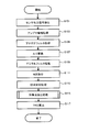
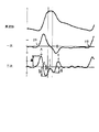
- FIG. 4 is a flowchart showing an analysis process of a pressure signal (sensor signal) obtained from a sensor element included in a semiconductor pressure sensor 19 in the pulse wave analysis apparatus according to the embodiment. It is a figure which shows the specific example of the relationship between a pulse wave waveform, a primary differential wave, and a secondary differential wave. It is a figure which shows the characteristic of a zero crossing point. It is a figure which shows the characteristic of a zero crossing point. It is a figure which shows the characteristic of a zero crossing point. It is a figure which shows the usage example of a 4th-order differentiation. It is a figure for demonstrating the frequency characteristic of a 4th-order differential filter. It is a flowchart which shows the specific flow of the process which extracts the feature point in the pulse wave analysis apparatus concerning embodiment. It is a figure which shows the specific example of the bandpass filter used with the pulse wave analyzer concerning embodiment.
- the pulse wave analyzer includes a sensor unit 1, a display unit 3, and a fixed base unit 7.
- the display unit 3 is provided so as to be operable from the outside, and is operated to input various information related to pulse wave analysis and the like, and for outputting various information such as pulse wave analysis results to the outside.
- a display unit 25 including an LED (Light Emitting Diode) or an LCD (Liquid Crystal Display) is included.
- the fixed base unit 7 centrally controls the ROM (Read Only Memory) 12 and RAM (Random Access Memory) 13 for storing data and programs for controlling the pulse wave analyzer and the pulse wave analyzer.
- a CPU (Central Processing Unit) 11 that executes various processes including calculation, a pressure pump 15, a negative pressure pump 16, a switching valve 17, and a signal from the CPU 11 are received, and the pressure pump 15, the negative pressure pump 16, and the switching valve 17 includes a control circuit 14 for transmitting to 17, a variable characteristic filter 22 that can be changed to at least two values, and an A / D converter 23.
- the CPU 11 accesses the ROM 12, reads the program, develops it on the RAM 13, and executes it, thereby controlling the entire pulse wave analyzing apparatus.
- CPU11 receives the operation signal from a user from the operation part 24, and controls the whole pulse-wave analyzer based on the operation signal. That is, the CPU 11 sends a control signal to the control circuit 14, the multiplexer 20, and the characteristic variable filter 22 based on the operation signal input from the operation unit 24. Further, the CPU 11 performs control for displaying the pulse wave analysis result on the display unit 25.
- the pressurizing pump 15 is a pump for pressurizing an internal pressure (hereinafter referred to as “cuff pressure”) of a press cuff (air bag) 18 described later, and the negative pressure pump 16 is a pump for reducing the cuff pressure. is there.
- the switching valve 17 selectively connects one of the pressurizing pump 15 and the negative pressure pump 16 to the air pipe 5.
- the control circuit 14 controls these according to a control signal from the CPU 11.
- the sensor unit 1 includes a semiconductor pressure sensor 19 including a plurality of sensor elements, a multiplexer 20 for selectively deriving a pressure signal output from each of the plurality of sensor elements, and an amplifier 21 for amplifying the pressure signal output from the multiplexer 20. , And a pressure cuff 18 including an air bag that is pressure adjusted to press the semiconductor pressure sensor 19 onto the measurement site.
- the semiconductor pressure sensor 19 includes a plurality of sensor elements arranged at a predetermined interval in one direction on a semiconductor chip made of single crystal silicon or the like, and is pressed against a measurement site such as an upper arm during measurement by the pressure of the pressing cuff 18. In that state, the semiconductor pressure sensor 19 detects the pulse wave of the subject via the radial artery. The semiconductor pressure sensor 19 inputs a pressure signal output by detecting a pulse wave to the multiplexer 20 for each channel of each sensor element. For example, 40 sensor elements are arranged.
- the multiplexer 20 selectively outputs a pressure signal output from each sensor element.
- the pressure signal sent from the multiplexer 20 is amplified by the amplifier 21 and selectively output to the A / D converter 23 via the characteristic variable filter 22.
- the multiplexer 20 sequentially switches a plurality of pressure signals output from a plurality of sensor elements in accordance with a control signal from the CPU 11 until an optimum sensor element for pulse wave detection is selected. Output. Further, after the optimum sensor element for pulse wave detection is selected, it is fixed to the corresponding channel in accordance with a control signal from the CPU 11. At this time, the multiplexer 20 selects and outputs the pressure signal output from the selected sensor element.
- the characteristic variable filter 22 is a low-pass filter for blocking signal components of a predetermined value or more, and can be changed to at least two values.
- the A / D converter 23 converts the pressure signal, which is an analog signal derived from the semiconductor pressure sensor 19, into digital information and gives it to the CPU 11. Until the channel of the multiplexer 20 is fixed by the CPU 11, the pressure signals output from the sensor elements included in the semiconductor pressure sensor 19 are simultaneously acquired via the multiplexer 20. Then, after the channel of the multiplexer 20 is fixed by the CPU 11, the pressure signal output from the corresponding sensor element is acquired.
- the period during which the pressure signal is sampled (hereinafter referred to as “sampling period”) is, for example, 2 ms.
- the characteristic variable filter 22 changes the cutoff frequency value until the channel of the multiplexer 20 is fixed and after the channel is fixed. Until the channel of the multiplexer 20 is fixed, a plurality of pressure signals are switched and sampled. Therefore, a cutoff frequency value higher than the sampling frequency (for example, 20 kHz) at this time is selected. Thereby, it is possible to prevent rounding after A / D conversion, and it is possible to appropriately select an optimum sensor element. After the channel is fixed, according to the control signal from the CPU 11, a value that becomes a cut-off frequency that is 1 ⁇ 2 or less of a sampling frequency (for example, 500 Hz) for a certain pressure signal is selected.
- a sampling frequency for example, 500 Hz
- Aliasing noise is noise that has a frequency component that is 1/2 or more of the sampling frequency that appears in an area that is 1/2 or less of the sampling frequency due to the aliasing phenomenon when an analog signal is converted to a digital signal by the sampling theorem. Point to.
- the size of the display unit 3 can be reduced.
- the fixed base unit 7 and the display unit 3 are provided separately, a configuration in which the display unit 3 is built in the fixed base unit 7 may be employed.
- the display unit 3 may be provided with a CPU 11, ROM 12, and RAM 13. It may be connected to a PC (Personal Computer) to perform various controls.
- PC Personal Computer
- the pulse wave analysis device uses the duration of the reflected wave in the measured pulse wave (hereinafter referred to as TRD: Traveling time of Reflection-) as an index useful for diagnosis of heart diseases such as arteriosclerosis from the pulse wave waveform.
- wave (Duration) is calculated.
- PWV pulse wave velocity
- PTT Pulse Transmission Time
- TRD Transmission Time
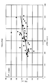
- FIG. 2 shows the relationship between PTT and TRD between the forearm and ankle
- FIG. 3 shows the relationship between PTT and TRD between the neck and thigh.
- the inventors of the present application calculate PWV and TRD from many pulse wave samples and verify that there is a correlation between them.
- FIG. 4 shows the relationship between PWV and TRD between the forearm and ankle
- FIG. 5 shows the relationship between PWV and TRD between the neck and thigh. From these verifications, TRD can also be an effective index for diagnosis of heart diseases such as arteriosclerosis.
- the former section of the two sections is a section in which vibration is extracted because a high-frequency component is included in the pulse wave of one beat measured as a composite wave, and the latter section includes a high-frequency component. It can be said that it is a section where vibration is not extracted. In other words, the former section can be said to be a vibration section, and the latter section can be said to be a stable section.
- the pulse wave analysis apparatus extracts the start point and end point of at least one of the two sections as feature points from the measured pulse wave.
- the processing shown in the flowchart of FIG. 6 is realized by the CPU 11 in the fixed base unit 7 accessing the ROM 12, reading the program, developing it on the RAM 13, and executing it.
- at least a part of the processing may be realized by the hardware configuration illustrated in FIG. This process will be described as an analysis process after the channel of the multiplexer 20 is fixed.
- step S101 the semiconductor pressure sensor 19 having a plurality of sensor elements inputs the pressure signal to the multiplexer 20 when detecting the pressure signal.
- the multiplexer 20 selects the sensor signal output from the sensor element corresponding to the fixed channel.
- the pressure signal selected by the multiplexer 20 is input to the amplifier 21.
- step S103 the amplifier 21 amplifies the pressure signal to a predetermined amplitude, and in step S105, the variable characteristic filter 22 performs analog filtering. At this time, the characteristic variable filter 22 cuts off a signal component that is 1 ⁇ 2 or less of the sampling frequency. If the sampling frequency is 500 Hz, for example, signal components having a frequency exceeding 100 Hz are blocked.
- step S107 the A / D converter 23 digitizes the pressure signal that has passed through the variable characteristic filter 22, and in step S109, performs digital filter processing for extracting a predetermined range of frequencies for the purpose of noise removal or the like.
- the A / D converter 23 transfers the digitized pressure signal to the CPU 11.
- step S111 the CPU 11 receives the pressure signal from the A / D converter 23, and takes the first to fifth differentials by taking the difference of each data.
- the CPU 11 executes the program stored in the ROM 12 to perform Nth order differentiation of the pulse wave waveform obtained from the pressure signal.
- step S113 the CPU 11 extracts a pulse wave waveform of one beat by dividing the pulse wave waveform based on the differentiation result. Specifically, the CPU 11 waits for the first derivative to become positive among the Nth derivative acquired in step S111. When the first derivative becomes positive, the rising zero-cross point is held, and this is set as a “provisional rising point”. And it waits for the maximum of the first derivative. When detecting the maximum of the first derivative, the CPU 11 determines whether one beat has been recognized.
- the waveform from the immediately preceding rising point (PA point) to the preceding rising point (PB point) is referred to.
- the maximum point (PP point) of the original waveform exists between the PA point and the PB point, and it is confirmed that the PB point is the minimum value between the PP point and the PB point. If it is confirmed that the PB point is the minimum value, the PA point is determined as the “rising point”. Then, a pulse wave waveform of one beat is formed from the PA point to the PB point.
- the PA point can also be defined as a “pulse wave start point” of one beat.
- step S115 the CPU 11 extracts a predetermined feature point from the pulse wave waveform of one beat cut out in step S113, and calculates TRD in step S117. This completes the sensor signal analysis process.
- the necessary feature points for calculating the TRD include the start point and the end point of at least one of the vibration section and the stable section described above.
- the pulse wave analyzing apparatus extracts the start and end points of the vibration section, that is, the convergence time of the reflected wave component of the pulse wave waveform of one beat.
- the zero-cross point of the fourth-order differential wave obtained from the original waveform is often used.
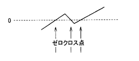
- a clear zero-cross point as shown in FIG. 8A is not always extracted from the zero-cross point due to the influence of a change in the baseline or the like.
- the zero cross point may be obscured.
- FIG. 8B shows a case where there are a plurality of zero-cross points and the zero-cross points to be extracted as feature points of the pulse wave waveform are unclear.
- FIG. 8C shows the case where the zero cross point is unclear because the time for zero continues. In the case of an unclear zero-cross point as shown in FIGS.
- waveform 41 is a waveform representing equation (1)
- waveform 42 is a waveform representing “sin (2t)” in equation (1)
- waveform 43 is equation (2). It is the waveform showing.
- a waveform 43 shows substantially the same phase as the waveform 42. Therefore, the maximum point of the high-frequency component included in the signal can be grasped as the maximum point of the fourth derivative.
- traveling waves and reflected waves have a high frequency with respect to the pulse wave period. Therefore, it is considered that the maximum point of the traveling wave and the reflected wave can be extracted by calculating the maximum point of the fourth derivative wave of the pulse wave.
- the first local maximum from the rising edge of the fourth-order differential wave of the pulse wave waveform of one beat can be extracted as the maximum point of the traveling wave, and the next maximum point can be extracted as the maximum point of the reflected wave. Therefore, the pulse wave analysis apparatus according to the present embodiment extracts the former maximum point as a feature point indicating the start point of the vibration section.
- the end point of the vibration section is obtained as the vibration convergence point.
- the amplitude of the reflected wave component in the original waveform is determined from the amplitude of the first local maximum point from the rise of the fourth-order differential wave of the pulse waveform of one beat corresponding to the peak of the traveling wave component of the original waveform. It shall be determined that the specified percentage has been reached.
- An example of the above-mentioned prescribed ratio is about 10%. Therefore, the pulse wave analysis apparatus according to the present embodiment extracts the above points as feature points indicating the end points of the vibration sections.
- the fourth-order differential wave tends to react to high frequency noise. Therefore, it may be difficult to extract the maximum points of the traveling wave and the reflected wave as the characteristic points of the pulse wave analysis.
- the maximum frequency included can be adjusted by changing ⁇ h (hereinafter simply referred to as “ ⁇ h”), which is the interval for taking the difference in data.
- FIG. 10 shows an example in which ⁇ h is 8 ms, 12 ms, 16 ms, 24 ms, and 32 ms with respect to the original waveform.
- the waveform is 52
- the waveform when the 12 ms is the waveform 53
- the waveform when the 16 ms is the waveform 54
- 24 ms The waveform when the waveform is 55 and 32 ms is represented by the waveform 56.
- waveform 56 for example, when comparing waveform 52 and waveform 56, it can be seen that the amplitude of waveform 52 is finer and that a high frequency component is extracted.
- the waveform 56 has a gentle amplitude, and it can be seen that only low frequency components are extracted. Therefore, the pulse wave component can be selectively extracted by adjusting the frequency characteristic of the fourth-order differential filter.
- the inventors of the present application have performed an actual simulation and confirmed that the feature points of the pulse wave are accurately extracted using the maximum point of the fourth order differential obtained by using the fourth order differential filter. The results are disclosed in Japanese Patent Application Laid-Open No. 2005-349116, which was filed and published by the present inventors.
- the pulse wave analysis apparatus extracts pulse wave feature points by using the poles of the fourth-order differential wave obtained from the fourth-order differential filter.
- ⁇ h is set longer than the data sampling period (2 ms) in the fourth-order differential filter. Thereby, the noise contained in a high frequency component can be reduced.
- ⁇ h is set to 32 ms.
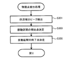
- FIG. 11 is a flowchart showing a specific flow of the process of extracting feature points in step S115.
- CPU 11 when recognizing a pulse wave of 1 beat in step S113, CPU 11 obtains the maximum value of the second derivative existing between the PA point and the PB point shown in FIG. The maximum value of the second derivative obtained here is in order A point (hereinafter referred to as “APG-A point”), C point (hereinafter referred to as “APG-C point”), E point (hereinafter referred to as “APG-E point”). ).
- APG-A point A point
- C point hereinafter referred to as “APG-C point”
- E point hereinafter referred to as “APG-E point”.
- the CPU 11 obtains the maximum points of the fourth derivative existing between the PA point and the APG-E point.
- the acquired maximal point of the fourth derivative is set as a candidate for the maximum point of the traveling wave and the reflected wave.
- step S303 the CPU 11 sets the maximum point of the reflected wave, which is one of the characteristic points, among the maximum points of the fourth derivative existing in the descending leg section from the PP point to the APG-E point (P2 Point), and that point is determined as the starting point of the vibration section.
- the PP point may be the maximum point of the traveling wave or the maximum point of the reflected wave. Accordingly, the “falling leg section” simply refers to a section from the pulse wave maximum point (PP point) to the notch point (APG-E point).
- the APG-E point is used in the analysis as a point representing the timing of aortic closure. Such a point on the pulse wave representing the timing of aortic closure is defined as a “notch point”.
- the CPU 11 may calculate the maximum reflected wave point (P2 point) using the maximum point of the fourth-order differential wave in the section from the APG-C point to the APG-E point.
- step S305 the CPU 11 calculates, as a threshold, 10% of the amplitude of the PP point that is the peak of the traveling wave corresponding to the first local maximum point from the rising point that is the PA point shown in FIG. Then, the zero-cross point of the fourth-order differential wave next to the point where the amplitude has reached the threshold value after the PP point is acquired as a convergence point of vibration that is one of the feature points, and that point is the end of the vibration section. Decide on a point.
- step S117 the CPU 11 uses the time indicating the end point as the index by subtracting the time indicating the start point. Calculate TRD.
- the pulse wave analysis device extracts the start point and end point of a vibration section that can be easily extracted from the measured pulse wave waveform as feature points, and calculates TR as an index based on the feature points.
- TR has a correlation with an index that is already known to be useful for diagnosis of heart disease, and TR itself is also a useful index. I can say that. Therefore, in the pulse wave analyzer according to the present embodiment, feature points can be extracted from a waveform measured with high accuracy, and an index useful for diagnosis of heart disease can be calculated.
- the present invention is not limited to a specific measurement site, and for example, it is possible to measure a pulse wave even with the upper arm, so that it can be easily used even in ordinary households. In addition, when measuring a pulse wave with the upper arm, it is not necessary to perform measurement by the recumbent position as the measurement position, so that the burden on the measurement subject can be suppressed.
- FIG. 12 shows a specific example of the band-pass filter used in the digital filter processing in step S109.
- the band-pass filter shown in FIG. 12 is used for the digital filter processing in step S109, so that the pressure signal digitized in step S107 has a frequency component equal to or lower than the threshold value fcl and a threshold value fch or higher.
- the ingredients are cut.
- a band-pass filter is usually used to cut a low frequency lower than a predetermined frequency.
- the predetermined frequency for the purpose of removing the influence of body movement is, for example, about 0.5 Hz, and 0.5 Hz or the like is set as the low-frequency side threshold fcl.
- the pulse wave with a frequency less than 3 Hz has a pulse wave velocity different from that of other frequencies
- the pulse wave component with a frequency less than 3 Hz can be an error factor.
- the paper “Regional by McDonald DA” Known as pulse-wave velocity in the arterial tree, "(J Appl Physiol., 1968; Jan; 24 (1): pp. 73-78).
- the amplitude of the pulse wave component with a frequency of less than 5 Hz is amplified at the stage of propagation to the upper arm.
- the digital filter processing in step S109 is preferably performed to the pulse wave of each element of body movement, propagation speed dependence on frequency, and amplitude amplification at the stage of propagation to the upper arm.
- the threshold fcl on the low frequency side is determined to be 5 Hz in consideration of these noise components.
- the fourth-order differential wave is used to extract the feature point from the pulse wave in the pulse wave analyzer, but a band-pass filter may be used by using the above-described concept.
- the third-order or higher-order differential wave is not limited to the fourth-order differential wave.
- the fourth-order differential wave since the fourth-order differential wave has high accuracy for obtaining a feature point experimentally, the fourth-order differential wave is preferably used. Use.
- the process of extracting the start point and end point of the vibration section as the feature points in step S115 is not limited to the above method.
- another method will be described. That is, as another method of the above processing, the moving average value of the fourth-order differential wave of the pulse wave of one beat is calculated, the point reaching the maximum value is extracted as the starting point of the vibration section, and the maximum value is reached. Thereafter, a method of extracting a point where the moving average value does not exceed a value that is lower than the maximum value by a specified percentage as the end point of the vibration section can be mentioned.
- a configuration is described in which a pulse wave is detected by capturing a change in pressure using a pressure sensor, but the pulse wave detection method is not limited to the above configuration.
- the described analysis method of the pulse waveform is not limited to the analysis of the pulse waveform.
- a first waveform and a second waveform generated by contraction and expansion of the heart such as a heartbeat waveform, are synthesized. It can also be used for analysis of other biological waves.
- pulse wave analysis in the above-described pulse wave analysis apparatus that is, a feature point extraction method and an index calculation method can be provided as a program.
- a program is stored on a computer-readable recording medium such as a flexible disk, CD-ROM (Compact Disk-Read Only Memory), ROM (Read Only Memory), RAM (Random Access Memory), and memory card attached to the computer.
- the program can be provided by being recorded on a recording medium such as a hard disk built in the computer.
- a program can also be provided by downloading via a network.
- the program according to the present invention is a program module that is provided as a part of a computer operating system (OS) and calls necessary modules in a predetermined arrangement at a predetermined timing to execute processing. Also good. In that case, the program itself does not include the module, and the process is executed in cooperation with the OS. A program that does not include such a module can also be included in the program according to the present invention.
- OS computer operating system
- the program according to the present invention may be provided by being incorporated in a part of another program. Even in this case, the program itself does not include the module included in the other program, and the process is executed in cooperation with the other program. Such a program incorporated in another program can also be included in the program according to the present invention.
- the provided program product is installed in a program storage unit such as a hard disk and executed.
- the program product includes the program itself and a recording medium on which the program is recorded.
Landscapes
- Health & Medical Sciences (AREA)
- Life Sciences & Earth Sciences (AREA)
- Engineering & Computer Science (AREA)
- Cardiology (AREA)
- Medical Informatics (AREA)
- Animal Behavior & Ethology (AREA)
- Physiology (AREA)
- Biophysics (AREA)
- Pathology (AREA)
- Veterinary Medicine (AREA)
- Biomedical Technology (AREA)
- Heart & Thoracic Surgery (AREA)
- Public Health (AREA)
- Molecular Biology (AREA)
- Surgery (AREA)
- Physics & Mathematics (AREA)
- General Health & Medical Sciences (AREA)
- Vascular Medicine (AREA)
- Signal Processing (AREA)
- Artificial Intelligence (AREA)
- Computer Vision & Pattern Recognition (AREA)
- Psychiatry (AREA)
- Ophthalmology & Optometry (AREA)
- Hematology (AREA)
- Measuring Pulse, Heart Rate, Blood Pressure Or Blood Flow (AREA)
- Radar Systems Or Details Thereof (AREA)
Abstract
Description


上記ステップS115で特徴点として振動区間の開始点および終了点を抽出する処理は上の方法に限定されない。変形例として、他の方法について説明する。すなわち、上記処理の他の方法として、1拍の脈波の4次微分波の移動平均値を算出し、その最大値に達した点を振動区間の開始点として抽出し、最大値に達した後、以降、移動平均値がその最大値から規定割合下回った値を超えない点を振動区間の終了点として抽出する方法が挙げられる。
Claims (7)
- 脈波を検出するための脈波検出部(1)と、
前記脈波検出部で検出された脈波に基づく処理を行なうための演算装置(11)とを含み、
前記演算装置で行なわれる処理は、
1拍の脈波波形から反射波区間を区分するための特徴点を抽出する処理(S115)と、
前記反射波の収束時間を指標として算出する処理(S117)とを含む、脈波解析装置。 - 前記脈波検出部からの脈波信号をデジタル信号に変換するためのデジタル変換部(23)と、
前記デジタル変換部によって変換された前記デジタル信号に基づき、原波形の4次微分波を得るための、周波数特性の調整が可能な4次微分フィルタ(22)とをさらに含み、
前記演算装置で行なわれる処理は、1拍の脈波の区間における前記4次微分波の極点を算出する処理(S301)をさらに含み、
前記特徴点を抽出する処理は、
前記4次微分波の極点に基づき、前記反射波区間の開始点を抽出する処理(S303)と、
前記4次微分波の振幅に基づき、前記反射波区間の終了点を抽出する処理(S305)とを含む、請求の範囲第1項に記載の脈波解析装置。 - 前記反射波区間の開始点を抽出する処理では、前記1拍の脈波の立ち上がり点から1つ目の前記4次微分波の極大点を、前記反射波区間の開始点である前記特徴点として抽出し、
前記反射波区間の終了点を抽出する処理では、前記1拍の脈波の立ち上がり点から最初の前記4次微分波の極点に相当する点の前記脈波の振幅から、前記極点に相当する点以降で前記脈波の振幅が規定の割合に達した点を、前記反射波区間の終了点である前記特徴点として抽出する、請求の範囲第2項に記載の脈波解析装置。 - 前記反射波区間の開始点を抽出する処理では、前記1拍の前記4次微分波の移動平均値が最大の点を、前記反射波区間の開始点である前記特徴点として抽出し、
前記反射波区間の終了点を抽出する処理では、前記1拍の前記4次微分波の移動平均値が前記最大の点に達した後に、以降、当該最大値から規定割合下回った値を移動平均値が超えない点を、前記反射波区間の終了点である前記特徴点として抽出する、請求の範囲第2項に記載の脈波解析装置。 - 前記演算装置で行なわれる処理は、前記1拍の脈波の区間における前記4次微分波の移動平均値よりノイズ成分をオフセットして除外するためのフィルタ処理をさらに含む、請求の範囲第2項に記載の脈波解析装置。
- 脈波を検出するための圧力センサで得られた1拍の脈波波形から反射波区間を区分するための特徴点を抽出するステップ(S115)と、
前記反射波の収束時間を指標として算出するステップ(S117)とを備える、脈波解析方法。 - 脈波を解析し、指標を算出する処理をコンピュータに実行させるためのプログラムであって、
脈波を検出するための圧力センサからセンサ信号を取得するステップ(S101)と、
前記センサ信号に基づいた1拍の脈波波形から、反射波区間を区分するための特徴点を抽出するステップ(S115)と、
前記反射波の収束時間を指標として算出するステップ(S117)とを実行させる、脈波解析プログラム。
Priority Applications (4)
| Application Number | Priority Date | Filing Date | Title |
|---|---|---|---|
| DE112010000746T DE112010000746T5 (de) | 2009-02-03 | 2010-01-28 | Pulswellen-Analysierglied und Pulswellen-Analysierverfahren |
| CN201080006542.XA CN102307520B (zh) | 2009-02-03 | 2010-01-28 | 脉搏波分析装置以及脉搏波分析方法 |
| RU2011136627/14A RU2526450C2 (ru) | 2009-02-03 | 2010-01-28 | Анализатор пульсовой волны и способ анализа пульсовой волны |
| US13/189,634 US20110282224A1 (en) | 2009-02-03 | 2011-07-25 | Pulse wave analyzer and pulse wave analyzing method |
Applications Claiming Priority (2)
| Application Number | Priority Date | Filing Date | Title |
|---|---|---|---|
| JP2009022972A JP5200968B2 (ja) | 2009-02-03 | 2009-02-03 | 脈波解析装置、脈波解析方法、および脈波解析プログラム |
| JP2009-022972 | 2009-02-03 |
Related Child Applications (1)
| Application Number | Title | Priority Date | Filing Date |
|---|---|---|---|
| US13/189,634 Continuation US20110282224A1 (en) | 2009-02-03 | 2011-07-25 | Pulse wave analyzer and pulse wave analyzing method |
Publications (1)
| Publication Number | Publication Date |
|---|---|
| WO2010090122A1 true WO2010090122A1 (ja) | 2010-08-12 |
Family
ID=42542020
Family Applications (1)
| Application Number | Title | Priority Date | Filing Date |
|---|---|---|---|
| PCT/JP2010/051118 Ceased WO2010090122A1 (ja) | 2009-02-03 | 2010-01-28 | 脈波解析装置および脈波解析方法 |
Country Status (7)
| Country | Link |
|---|---|
| US (1) | US20110282224A1 (ja) |
| JP (1) | JP5200968B2 (ja) |
| KR (1) | KR101654390B1 (ja) |
| CN (1) | CN102307520B (ja) |
| DE (1) | DE112010000746T5 (ja) |
| RU (1) | RU2526450C2 (ja) |
| WO (1) | WO2010090122A1 (ja) |
Cited By (2)
| Publication number | Priority date | Publication date | Assignee | Title |
|---|---|---|---|---|
| JP2010178801A (ja) * | 2009-02-03 | 2010-08-19 | Omron Healthcare Co Ltd | 脈波解析装置、脈波解析方法、および脈波解析プログラム |
| CN104640500A (zh) * | 2012-09-25 | 2015-05-20 | 欧姆龙健康医疗事业株式会社 | 血压测定装置、脉搏波检测方法 |
Families Citing this family (18)
| Publication number | Priority date | Publication date | Assignee | Title |
|---|---|---|---|---|
| TWI459926B (zh) * | 2011-08-19 | 2014-11-11 | 中原大學 | Pulse pressure signal measurement system and its measurement method |
| JP5628234B2 (ja) * | 2012-03-26 | 2014-11-19 | 株式会社デンソーアイティーラボラトリ | 血流簡易検査装置及び血流簡易検査方法並びに血流簡易検査用プログラム |
| JP5991100B2 (ja) | 2012-09-13 | 2016-09-14 | オムロンヘルスケア株式会社 | 脈拍測定装置、脈拍測定方法、および脈拍測定プログラム |
| JP6149548B2 (ja) * | 2013-07-01 | 2017-06-21 | オムロンヘルスケア株式会社 | 電子血圧計 |
| CN103720462A (zh) * | 2013-11-06 | 2014-04-16 | 路红生 | 脉搏波信号分析方法和装置 |
| JP5911840B2 (ja) * | 2013-11-25 | 2016-04-27 | 株式会社カオテック研究所 | 診断データ生成装置および診断装置 |
| CN104545853A (zh) * | 2014-12-26 | 2015-04-29 | 河南机电高等专科学校 | 一种基于双ppg的血压测量方法和装置 |
| CN105078438B (zh) * | 2015-06-19 | 2017-08-11 | 京东方科技集团股份有限公司 | 脉搏周期检测设备和方法和可穿戴电子设备 |
| KR102501837B1 (ko) * | 2015-11-09 | 2023-02-21 | 삼성전자주식회사 | 신호 특징 추출 방법 및 장치 |
| KR20170054030A (ko) * | 2015-11-09 | 2017-05-17 | 삼성전자주식회사 | 생체 신호의 특징을 추출하는 방법 및 장치 |
| KR102655669B1 (ko) * | 2016-07-20 | 2024-04-05 | 삼성전자주식회사 | 생체신호의 특징 추출 장치 및 방법과, 생체정보 검출 장치 |
| JP6706996B2 (ja) * | 2016-08-05 | 2020-06-10 | 日本電信電話株式会社 | 生体信号処理装置、異常判別方法およびプログラム |
| CN110477889B (zh) * | 2018-10-08 | 2021-11-02 | 合肥伊阳健康科技有限公司 | 识别桡动脉压力波形反射点的方法和装置 |
| CN110693474B (zh) * | 2018-10-08 | 2022-02-15 | 合肥伊阳健康科技有限公司 | 识别桡动脉压力波形重搏波特征点的方法和装置 |
| CN110292369A (zh) * | 2019-07-03 | 2019-10-01 | 浙江大学 | 基于脉搏波传导时间的胸口无创血压检测探头及其装置 |
| KR102567952B1 (ko) * | 2019-09-11 | 2023-08-16 | 삼성전자주식회사 | 생체정보 추정 장치 및 방법 |
| CN111358498B (zh) * | 2020-03-23 | 2021-08-24 | 贵州民族大学 | 去除超声脉搏波上冲段反射波和量化噪声的方法及系统 |
| CN113100727B (zh) * | 2021-05-12 | 2023-09-19 | 深圳市通久电子有限公司 | 实时分析识别脉搏波峰的方法 |
Citations (2)
| Publication number | Priority date | Publication date | Assignee | Title |
|---|---|---|---|---|
| JP2003305012A (ja) * | 2002-04-17 | 2003-10-28 | Nippon Colin Co Ltd | 振幅増加指数測定装置 |
| JP2005349116A (ja) * | 2004-06-14 | 2005-12-22 | Omron Healthcare Co Ltd | 脈波解析装置および脈波解析プログラム |
Family Cites Families (9)
| Publication number | Priority date | Publication date | Assignee | Title |
|---|---|---|---|---|
| JPS61149131A (ja) * | 1984-12-25 | 1986-07-07 | 株式会社東芝 | 超音波診断装置 |
| US5265011A (en) * | 1989-04-03 | 1993-11-23 | Eastern Medical Testing Services, Inc. | Method for ascertaining the pressure pulse and related parameters in the ascending aorta from the contour of the pressure pulse in the peripheral arteries |
| RU2127999C1 (ru) * | 1997-01-24 | 1999-03-27 | Лузянин Андрей Геннадьевич | Неинвазивный способ определения параметров гемодинамики в биообъектах и устройство для его осуществления |
| EP1372473A4 (en) * | 2001-03-09 | 2009-06-03 | Auckland Uniservices Ltd | APPARATUS AND METHOD FOR DETECTING AND QUANTIFYING OSCILLATORY SIGNALS |
| JP3632014B2 (ja) * | 2002-05-14 | 2005-03-23 | コーリンメディカルテクノロジー株式会社 | 血管内皮機能評価装置 |
| JP4517619B2 (ja) * | 2002-12-05 | 2010-08-04 | オムロンヘルスケア株式会社 | 脈波測定装置 |
| JP2004313468A (ja) * | 2003-04-16 | 2004-11-11 | Omron Healthcare Co Ltd | 脈波測定装置および生体波解析プログラム |
| US20090312653A1 (en) * | 2008-06-16 | 2009-12-17 | Sharrock Nigel E | Method and apparatus for determining cardiac medical parameters from supra-systolic signals obtained from an oscillometric blood pressure system |
| JP5200968B2 (ja) * | 2009-02-03 | 2013-06-05 | オムロンヘルスケア株式会社 | 脈波解析装置、脈波解析方法、および脈波解析プログラム |
-
2009
- 2009-02-03 JP JP2009022972A patent/JP5200968B2/ja active Active
-
2010
- 2010-01-28 KR KR1020117017125A patent/KR101654390B1/ko active Active
- 2010-01-28 RU RU2011136627/14A patent/RU2526450C2/ru active
- 2010-01-28 DE DE112010000746T patent/DE112010000746T5/de active Pending
- 2010-01-28 CN CN201080006542.XA patent/CN102307520B/zh active Active
- 2010-01-28 WO PCT/JP2010/051118 patent/WO2010090122A1/ja not_active Ceased
-
2011
- 2011-07-25 US US13/189,634 patent/US20110282224A1/en not_active Abandoned
Patent Citations (2)
| Publication number | Priority date | Publication date | Assignee | Title |
|---|---|---|---|---|
| JP2003305012A (ja) * | 2002-04-17 | 2003-10-28 | Nippon Colin Co Ltd | 振幅増加指数測定装置 |
| JP2005349116A (ja) * | 2004-06-14 | 2005-12-22 | Omron Healthcare Co Ltd | 脈波解析装置および脈波解析プログラム |
Cited By (3)
| Publication number | Priority date | Publication date | Assignee | Title |
|---|---|---|---|---|
| JP2010178801A (ja) * | 2009-02-03 | 2010-08-19 | Omron Healthcare Co Ltd | 脈波解析装置、脈波解析方法、および脈波解析プログラム |
| CN104640500A (zh) * | 2012-09-25 | 2015-05-20 | 欧姆龙健康医疗事业株式会社 | 血压测定装置、脉搏波检测方法 |
| CN104640500B (zh) * | 2012-09-25 | 2016-12-21 | 欧姆龙健康医疗事业株式会社 | 血压测定装置、脉搏波检测方法 |
Also Published As
| Publication number | Publication date |
|---|---|
| US20110282224A1 (en) | 2011-11-17 |
| RU2011136627A (ru) | 2013-03-10 |
| KR20110123727A (ko) | 2011-11-15 |
| RU2526450C2 (ru) | 2014-08-20 |
| JP2010178801A (ja) | 2010-08-19 |
| CN102307520A (zh) | 2012-01-04 |
| CN102307520B (zh) | 2014-04-23 |
| JP5200968B2 (ja) | 2013-06-05 |
| DE112010000746T5 (de) | 2013-01-17 |
| KR101654390B1 (ko) | 2016-09-05 |
Similar Documents
| Publication | Publication Date | Title |
|---|---|---|
| JP5200968B2 (ja) | 脈波解析装置、脈波解析方法、および脈波解析プログラム | |
| JP4581496B2 (ja) | 脈波解析装置および脈波解析プログラム | |
| US6824519B2 (en) | Heart-sound detecting apparatus | |
| Obeid et al. | Evaluation of arterial stiffness by finger–toe pulse wave velocity: optimization of signal processing and clinical validation | |
| CA1081995A (en) | Apparatus and process using second derivative of oscillometric waveform for producing sphygmometric information | |
| US9119535B2 (en) | Blood pressure manometer and a method of calculating indices of atherosclerosis using the blood pressure manometer | |
| CN102743165B (zh) | 基于光电容积脉搏波的血液在体流动性测量装置 | |
| CN104757959B (zh) | 一种基于影像叠影的脉搏波传输速率检测方法和系统 | |
| CN102711597B (zh) | 脉搏波传播速度测定装置以及脉搏波传播速度测定程序 | |
| JP6129166B2 (ja) | 動脈の閉塞/再開を検出するための方法及び装置並びに収縮期血圧を測定するためのシステム | |
| JP2022091851A (ja) | 検出装置 | |
| JP3621395B2 (ja) | 波形解析機能付き血圧測定装置 | |
| WO2008029587A1 (fr) | Dispositif de mesure médicale destiné à la production d'informations utiles pour un diagnostic | |
| CN107863156A (zh) | 一种高血压筛查与管理方法与装置 | |
| CN102743160A (zh) | 一种无创精确的动脉功能测量装置 | |
| JP2002224059A (ja) | 電子血圧計 | |
| JP2001333889A (ja) | 血圧計 | |
| JP2002224055A (ja) | 電子血圧計 | |
| JP2014176427A (ja) | データ解析装置、及びデータ解析プログラム | |
| RU118534U1 (ru) | Устройство для оценки артериальной функции | |
| CN105358047B (zh) | 血管粘弹性评价装置、血管粘弹性评价方法以及程序 | |
| JP5206872B2 (ja) | 血管年齢推定装置 | |
| CN107752998B (zh) | 收缩压测量装置 | |
| CN121694716B (zh) | 基于上臂式血压计的脉搏波传导速度测量方法、装置 | |
| WO2019188768A1 (ja) | シャント音解析装置及び方法、コンピュータプログラム並びに記憶媒体 |
Legal Events
| Date | Code | Title | Description |
|---|---|---|---|
| WWE | Wipo information: entry into national phase |
Ref document number: 201080006542.X Country of ref document: CN |
|
| 121 | Ep: the epo has been informed by wipo that ep was designated in this application |
Ref document number: 10738456 Country of ref document: EP Kind code of ref document: A1 |
|
| ENP | Entry into the national phase |
Ref document number: 20117017125 Country of ref document: KR Kind code of ref document: A |
|
| WWE | Wipo information: entry into national phase |
Ref document number: 1120100007462 Country of ref document: DE Ref document number: 112010000746 Country of ref document: DE |
|
| WWE | Wipo information: entry into national phase |
Ref document number: 2011136627 Country of ref document: RU |
|
| 122 | Ep: pct application non-entry in european phase |
Ref document number: 10738456 Country of ref document: EP Kind code of ref document: A1 |