WO2010087003A1 - 発熱装置 - Google Patents
発熱装置 Download PDFInfo
- Publication number
- WO2010087003A1 WO2010087003A1 PCT/JP2009/051613 JP2009051613W WO2010087003A1 WO 2010087003 A1 WO2010087003 A1 WO 2010087003A1 JP 2009051613 W JP2009051613 W JP 2009051613W WO 2010087003 A1 WO2010087003 A1 WO 2010087003A1
- Authority
- WO
- WIPO (PCT)
- Prior art keywords
- terminal
- heat generating
- carbon
- metal terminal
- heating
- Prior art date
- Legal status (The legal status is an assumption and is not a legal conclusion. Google has not performed a legal analysis and makes no representation as to the accuracy of the status listed.)
- Ceased
Links
Images


Classifications
-
- C—CHEMISTRY; METALLURGY
- C01—INORGANIC CHEMISTRY
- C01B—NON-METALLIC ELEMENTS; COMPOUNDS THEREOF; METALLOIDS OR COMPOUNDS THEREOF NOT COVERED BY SUBCLASS C01C
- C01B33/00—Silicon; Compounds thereof
- C01B33/08—Compounds containing halogen
- C01B33/107—Halogenated silanes
- C01B33/1071—Tetrachloride, trichlorosilane or silicochloroform, dichlorosilane, monochlorosilane or mixtures thereof
-
- H—ELECTRICITY
- H05—ELECTRIC TECHNIQUES NOT OTHERWISE PROVIDED FOR
- H05B—ELECTRIC HEATING; ELECTRIC LIGHT SOURCES NOT OTHERWISE PROVIDED FOR; CIRCUIT ARRANGEMENTS FOR ELECTRIC LIGHT SOURCES, IN GENERAL
- H05B3/00—Ohmic-resistance heating
- H05B3/40—Heating elements having the shape of rods or tubes
-
- H—ELECTRICITY
- H05—ELECTRIC TECHNIQUES NOT OTHERWISE PROVIDED FOR
- H05B—ELECTRIC HEATING; ELECTRIC LIGHT SOURCES NOT OTHERWISE PROVIDED FOR; CIRCUIT ARRANGEMENTS FOR ELECTRIC LIGHT SOURCES, IN GENERAL
- H05B2203/00—Aspects relating to Ohmic resistive heating covered by group H05B3/00
- H05B2203/022—Heaters specially adapted for heating gaseous material
Definitions
- the present invention relates to a heat generating device.
- the present invention relates to a heat generating apparatus in a trichlorosilane production apparatus that converts tetrachlorosilane and hydrogen into trichlorosilane and a reaction tower using the same.
- Trichlorosilane is expected to increase in demand as a raw material gas for high-purity silicon used in elements such as semiconductors and solar cells, and there has been a demand for efficient production of these.
- trichlorosilane used as a raw material for producing high-purity silicon (Si: silicon) is converted by reacting tetrachlorosilane (SiCl 4 : silicon tetrachloride) with hydrogen. Manufactured by.
- trichlorosilane is produced by a conversion reaction according to the following reaction formula (1).
- SiCl 4 + H 2 ⁇ SiHCl 3 + HCl (1) This reaction is performed by heating a raw material gas consisting of tetrachlorosilane and hydrogen gasified in a carbon reaction vessel to about 800 ° C. to about 1300 ° C. And in order to improve the conversion rate to a trichlorosilane, the product gas of Reaction formula (1) is rapidly cooled.
- the target silicon is produced by the reduction reaction and thermal decomposition reaction of trichlorosilane according to the following reaction formulas (2) and (3).
- Patent Document 1 discloses a chlorosilane and hydrogen reaction vessel in which a reaction chamber surrounded by a heating element includes an outer chamber and an inner chamber formed by two concentric tubes.
- a supply gas of hydrogen and tetrachlorosilane is supplied from the lower part of the reaction chamber via a heat exchanger provided in the lower part of the reaction chamber, and the product gas after the reaction is discharged from the lower part of the reaction chamber.
- a reaction vessel has been proposed.
- Patent Document 2 discloses a reaction vessel in which a feed gas of tetrachlorosilane and hydrogen is supplied to the inside and a reaction product gas of trichlorosilane and hydrogen chloride is generated by a conversion reaction, and is arranged around the reaction vessel.
- Production of trichlorosilane mainly comprising a heating mechanism for heating the reaction vessel, a heat insulating material arranged to cover the reaction vessel and the surroundings of the heating mechanism, and a storage vessel for storing the reaction vessel, the heating mechanism and the heat insulating material
- An apparatus is disclosed.
- An object of the present invention is to provide a heat generating device capable of efficiently cooling the terminal portion of the heat generating device and suppressing corrosion and breakage of the component parts.
- the heating element includes a pair of heating elements, the heating element having a substantially cylindrical metal terminal, a substantially cylindrical carbon terminal, and a substantially cylindrical heating part, and a lower end of the metal terminal and the carbon terminal.
- the upper end is connected, the lower end of the carbon terminal and the upper end of the heat generating part are connected, the metal terminal has a water passage inside, and a gas containing tetrachlorosilane and hydrogen is supplied to the inside, so that trichlorosilane and chloride are supplied.
- a heating device is provided for heating a reaction vessel in which a gas containing hydrogen is produced.
- the terminal portion can be efficiently cooled, and damage to the components can be suppressed.
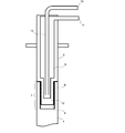
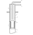
- FIG. 1 Schematic diagram of a heating device according to an embodiment of the present invention Schematic longitudinal cross-sectional view of the terminal part of the heat generating apparatus which concerns on embodiment of this invention Schematic longitudinal cross-sectional view of the terminal part of the heat generating apparatus which concerns on embodiment of this invention Schematic of a tetrachlorosilane reaction tower using a heating device according to an embodiment of the present invention
- Heat generating device 2 Heat generating element 3: Metal terminal 4: Carbon terminal 5: Heat generating portion 6: Water passage 7: Connection portion 8: Male screw portion 9: Female screw portion 10: Inlet 11: Discharge port 12: Water passage Bottom 13: injection tube 14: reaction tower 15: reaction vessel 16: outer cylinder 17: gas inlet 18: reaction product gas outlet
- the heat generating apparatus 1 includes a reaction vessel in which a gas containing tetrachlorosilane and hydrogen is supplied to generate a gas containing trichlorosilane and hydrogen chloride.
- a heating device 1 for heating wherein the heating device 1 includes a pair of heating elements 2, and the heating element 2 has a substantially cylindrical metal terminal 3, a substantially cylindrical carbon terminal 4, and a substantially cylindrical heat generation.
- a lower end portion of the metal terminal 3 and an upper end portion of the carbon terminal 4 are connected, a lower end portion of the carbon terminal 4 and an upper end portion of the heat generating portion 5 are connected, and the metal terminal 3 is It has a water passage 6 inside thereof.
- the heat generating apparatus 1 having the above-described configuration is provided with a characteristic water passage 6 inside the metal terminal 3 so that the terminal can be connected even at a high temperature of about 800 ° C. to about 1300 ° C., for example.
- the portion can be efficiently cooled, and corrosion and breakage of the component parts can be suppressed.
- the metal terminal 3 typically has a substantially cylindrical outer diameter from the heat-resistant surface, as in the case of conventionally used ones.
- the shape of the metal terminal 3 is not specifically limited, For example, a rectangular parallelepiped shape etc. may be sufficient.
- alloy materials such as SUS material which has heat resistance and SCC (stress corrosion cracking) resistance.
- SUS material which has heat resistance and SCC (stress corrosion cracking) resistance.
- SCC stress corrosion cracking
- an alloy having high SCC resistance such as Inconel 600 is preferable.
- the lower end portion of the metal terminal 3 is connected to the upper end portion of the carbon terminal 4 described later.
- a connecting means (connecting portion 7) for connecting the carbon terminal 4 is provided at the lower end portion of the metal terminal 3.
- the metal terminal 3 has a male screw portion 8
- the carbon terminal 4 has a female screw portion 9
- the metal terminal 3 and the carbon terminal. 4 is preferably configured to be screwed together in the male screw portion 8 and the female screw portion 9.
- the metal terminal 3 has a water passage 6 provided therein.
- the water passage 6 is for circulating cooling water for cooling the metal terminal 3, and as shown in FIG. 2 or 3, the inside of the substantially cylindrical metal terminal 3 is arranged in the axial direction.
- a cavity formed along the cavity, and an inlet 10 and an outlet 11 for cooling water following the cavity are provided.
- the shape of the water flow path 6 is not specifically limited, It is preferable that it is a cylindrical cavity shape which can circulate cooling water efficiently.
- the water passage 6 may be simply a metal terminal 3 provided with an inlet 10 and an outlet 11, but as shown in FIG. 2 or 3, the bottom of the water passage of the water passage 6. 12 is preferably provided with a cooling water injection pipe 13 that reaches 12.
- the cooling water flows into the lower end of the water passage 6 through the injection pipe 13 and is discharged from the upper discharge port 11.
- the cooling water circulates efficiently and can be cooled effectively.
- the depth of the water passage 6 that is, the position where the water passage 6 is formed at the lower end of the metal terminal 3, the bottom 12 of the water passage 6 of the water passage 6 is, as shown in FIG. It is preferable to be at a position reaching the screw portion 8.
- the connecting portion can be efficiently cooled, so that the corrosion of the connecting portion between the metal terminal 3 and the carbon terminal 4 is effectively suppressed. can do.
- the depth of the water passage 6 is preferably formed to a depth of 100%, more preferably 150% of the formation width of the male screw portion 8.
- the depth of the water passage 6 may be, for example, such that the bottom portion 12 of the water passage is above the male screw portion 8 at the lower end of the metal terminal 3 as shown in FIG.
- the diameter of the water passage 6 is not particularly limited as long as the metal terminal 3 is designed so that sufficient strength can be maintained, but may be in a range of 20% to 70% of the diameter of the metal terminal 3. preferable. In particular, if the diameter of the water passage 6 is 30% to 50% of the diameter of the metal terminal 3, the effect of increasing the water flow velocity and increasing the overall heat transfer coefficient can be obtained. Moreover, as shown in FIG. 2, it is preferable that the diameter of the water flow path 6 becomes small according to the diameter in the external thread part 8 of the lower end part of the metal terminal 3 part. Thus, by defining the diameter of the water passage 6 in accordance with the outer diameter of the metal terminal 3, cooling can be performed more effectively.
- a cooling liquid such as a calcium chloride aqueous solution, an ethylene glycol aqueous solution, or a propylene glycol aqueous solution, or a cooling gas such as cooling nitrogen may be flowed.
- the carbon terminal 4 is connected to the lower end portion of the metal terminal 3 at the upper end portion thereof, and is connected to the upper end portion of the heat generating portion 5 described later at the lower end portion thereof.
- Such a carbon terminal 4 is interposed between the metal terminal 3 and the heat generating portion 5, and the metal terminal 3 and the carbon terminal 4 are cooled to cause damage when a carbon heating element is directly connected to the metal terminal. Can be prevented.
- the diameter of the carbon terminal 4 is preferably larger than the diameter of the metal terminal 3 or the heat generating part 5. Thereby, the effect of reducing the calorific value can be obtained.
- the diameter of the carbon terminal 4 is preferably 1 to 2 times that of the metal terminal 3 and the heat generating portion 5. Since the diameter of the carbon terminal 4 is 1 to 2 times that of the metal terminal 3 or the heat generating portion 5, the effect of reducing the amount of heat generated can be obtained.
- the heat generating portion 5 is connected to the lower end portion of the carbon terminal 4 at the upper end portion thereof.
- the heat generating portion 5 and the carbon terminal 4 are preferably screwed together by, for example, a screw thread.
- the carbon of the carbon terminal 4 and / or the heat generating part 5 is preferably graphite.
- the effect of improving heat resistance can be obtained by using graphite.
- the silicon carbide film is not particularly limited, but typically can be formed by vapor deposition by a CVD method.
- a mixed gas of a silicon halide compound such as tetrachlorosilane or trichlorosilane and a hydrocarbon compound such as methane or propane is used.
- Method of use or heated carbon terminal 4 and heat generation while pyrolyzing a silicon halide compound having a hydrocarbon group such as methyltrichlorosilane, triphenylchlorosilane, methyldichlorosilane, dimethyldichlorosilane, trimethylchlorosilane with hydrogen A method of depositing silicon carbide on the surface of the portion 5 can be used.
- the thickness of the silicon carbide coating is preferably 10 to 500 ⁇ m, more preferably 30 to 300 ⁇ m. If the thickness of the silicon carbide coating is 10 ⁇ m or more, the corrosion of the carbon terminal 4 and the heat generating part 5 due to high-temperature water in the air can be sufficiently suppressed, and if it is 500 ⁇ m or less, the silicon carbide coating is cracked. Further, cracking of the carbon terminal 4 and the heat generating portion 5 is not promoted.
- the formed silicon carbide coating is a dense and uniform pinhole-free coating and is excellent in chemical stability. Therefore, in the heating device 1 constituted by the carbon terminal 4 and the heating section 5 provided with the silicon carbide coating, The frequency of equipment repair can be reduced, and the work efficiency can be further improved.
- the reaction tower 14 provided with the heat generating apparatus 1 according to the present embodiment will be described.
- the reaction tower 14 is supplied with a gas containing tetrachlorosilane and hydrogen, and heats the reaction vessel 15 in which a gas containing trichlorosilane and hydrogen chloride is generated.
- the heat generating device 1 is mainly composed of a reaction vessel 15 and an outer tube container 16 disposed so as to surround the heat generating device 1.
- the reaction vessel 15 is a substantially cylindrical vessel for reacting tetrachlorosilane and hydrogen in a high temperature environment.
- This container has a gas inlet 17 for taking in tetrachlorosilane as a raw material and hydrogen gas, and a reaction product gas outlet 18 for deriving a reaction product gas containing trichlorosilane and hydrogen chloride.
- the gas inlet 17 is provided at the bottom of the reaction vessel and the reaction product gas outlet 18 is provided above the reaction vessel 15, but these positions are limited to this. It is not a thing.
- a plurality of the heating devices 1 are installed with a predetermined interval between the reaction vessel 15 in the reaction tower 14 and the outer cylinder vessel 16.
- the heat generating apparatus 1 is installed in a state of being suspended from the reaction tower 14 as shown in FIG.
- the installation method of the heat generating device is not limited to the hanging type as described above.
- the heat generating device may be installed substantially vertically at the bottom of the reaction tower with the electrode on the lower side.
- the outer cylinder container 16 is a substantially cylindrical container having an outer side made of a metal such as stainless steel and a carbon panel or a refractory brick arranged on the inner side.
- the outer cylinder container 16 has a heat insulating performance and has a role of keeping the heat from the heat generating device 1 inside and maintaining the temperature in the reaction container 15.
- the reaction vessel 15 is heated by the heating device 1 disposed around it, so that tetrachlorosilane and hydrogen gas introduced from the gas introduction port 17 of the reaction vessel 15 have a high temperature of about 800 ° C. to about 1300 ° C. And is extracted from the reaction product gas outlet 18 of the reaction vessel 15 in the form of a reaction product gas containing trichlorosilane. Thereafter, the reaction product gas is supplied to a cooling device or the like in order to separate trichlorosilane.
- the heat generating device 1 includes a pair of heat generating elements, and the heat generating element includes a substantially cylindrical metal terminal, a substantially cylindrical carbon terminal, and a substantially cylindrical heat generating portion, and a lower end portion of the metal terminal. And the upper end of the carbon terminal are connected, the lower end of the carbon terminal and the upper end of the heat generating part are connected, the metal terminal has a water passage inside, and a gas containing tetrachlorosilane and hydrogen is supplied to the inside. It is a heat generating device for heating a reaction vessel in which a gas containing trichlorosilane and hydrogen chloride is generated. According to the heat generating device 1 having the above configuration, since the metal terminal 3 has the water passage 6, the terminal portion including the metal terminal 3 and the carbon terminal 4 can be efficiently cooled, and the heat of the component parts Damage due to expansion can be suppressed.
- the metal terminal 3 has a male screw portion 8 in the connecting portion 7 where the lower end portion of the metal terminal 3 and the upper end portion of the carbon terminal 4 are connected, and the carbon terminal 4 is
- the metal terminal 3 and the carbon terminal 4 have a female screw part 9, and the metal terminal 3 and the carbon terminal 4 can be removed and replaced by being screwed together in the male screw part 8 and the female screw part 9. It can be done easily.
- the diameter of the carbon terminal 4 is 1 to 2 times that of the metal terminal 3 or the heat generating portion 5, an effect of reducing the amount of heat generated can be obtained.
- the surface of the carbon terminal 4 and the heat generating part 5 can be protected from corrosion by applying a silicon carbide coating on the carbon terminal 4 and / or the heat generating part 5.
- the silicon carbide film is a silicon carbide film having a thickness of 10 ⁇ m to 500 ⁇ m formed by a CVD method, so that the carbon terminal 4 and heat generated by water in the air at a high temperature or the like are generated.
- the corrosion of the portion 5 can be sufficiently suppressed, and the crack of the silicon carbide film and the crack of the carbon terminal 4 and the heat generating portion 5 are not promoted.
- the heat generating device 1 when the carbon of the carbon terminal 4 and / or the heat generating part 5 is graphite, an effect of improving heat resistance can be obtained.
- a reaction vessel 15 in which a gas containing tetrachlorosilane and hydrogen is supplied to generate a gas containing trichlorosilane and hydrogen chloride, and the heating device 1 arranged so as to surround the reaction vessel 15,
- the metal terminal 3 has the water passage 6, so the metal terminal 3 and the carbon terminal 4 can be efficiently cooled, and damage due to thermal expansion of components can be suppressed.
- Example 1 A heating device using a metal terminal provided with a water passage as shown in FIG. 3 was prepared. As shown in FIG. 1, the heat generating device was made into a pair by combining two heat generating elements composed of a metal terminal (diameter 30 mm), a carbon terminal (diameter 30 mm), and a heat generating portion (diameter 20 mm). The diameter of the water passage was 50% of the diameter of the metal terminal. The connecting portion of each member is provided with a screw connection means and connected to each other.
- the heating device was installed inside the reaction tower and continuously operated for 2000 hours, and then the device was disassembled and examined for damage to the terminal portion. Furthermore, the operation was possible for 2000 hours.
- Example 2 In Example 2, the carbon terminal and the heat generating part are the same as those in Example 1, but as shown in FIG. 2, only a metal terminal that is deepened only in the depth of the water passage to reach the connecting part is used. A heating device similar to that in Example 1 was prepared except that the above was used. Then, an experiment similar to that in Example 1 was performed, and the device was disassembled to examine the damage of the terminal portion. As a result, the terminal portion was hardly damaged, and the operation for 2000 hours was possible three times.
- Example 3 In Example 3, the carbon terminal and the heat generating part are the same as those in Example 1, but the same as in Example 1 except that a metal terminal having a water passage diameter 1.5 times that of Example 1 was used. A heating device was created. Then, an experiment similar to that in Example 1 was performed, and the device was disassembled to examine the damage of the terminal portion. As a result, the terminal portion was hardly damaged, and the operation for 2000 hours was possible three times.
- Example 4 In Example 4, a heat generating device was created using the metal terminal and heat generating part of Example 2 and a carbon terminal (diameter 40 mm) having a diameter larger than that of the metal terminal. Then, an experiment similar to that in Example 1 was conducted, and the device was disassembled to examine the damage of the terminal portion. As a result, the terminal portion was hardly damaged, and the operation for 2000 hours was possible five times.
- Example 1 A heating device similar to that of Example 1 was prepared except that a metal terminal without a water passage was used. However, when the operation was performed, the heat generating device was damaged when 2000 hours had not passed. When dismantled, it was divided near the connection between the carbon terminal and the metal terminal.
- the terminal portion was hardly damaged and was excellent in durability.
- the heat generating devices according to Examples 2 to 4 can withstand multiple uses.
Landscapes
- Chemical & Material Sciences (AREA)
- Organic Chemistry (AREA)
- Inorganic Chemistry (AREA)
- Silicon Compounds (AREA)
Abstract
端子部を効率よく冷却することができ、構成部品の破損を抑制することができる発熱装置を提供する。 本願発明に係る発熱装置は、一対の発熱体からなり、発熱体は略円柱状の金属端子と略円柱状のカーボン端子と略円柱状の発熱部とを有し、金属端子の下端部とカーボン端子の上端部が連結し、カーボン端子の下端部と発熱部の上端部が連結し、金属端子がその内部に通水路を有し、テトラクロロシランと水素とを含むガスが内部に供給されトリクロロシランと塩化水素とを含むガスが生成される反応容器を加熱するための発熱装置である。
Description
本願発明は、発熱装置に関する。特に、テトラクロロシランと水素とを反応させてトリクロロシランに転換するトリクロロシラン製造装置における発熱装置、及びそれを用いた反応塔に関する。
トリクロロシランは、半導体や太陽電池等の素子に使用される高純度シリコンの原料ガスとして益々需要の増加が見込まれており、従来からこれらを効率良く製造することが要望されている。
一般的に、高純度のシリコン(Si:珪素)を製造するための原料として使用されるトリクロロシラン(SiHCl3)は、テトラクロロシラン(SiCl4:四塩化珪素)を水素と反応させて転換することで製造する。
即ち、トリクロロシランは、以下の反応式(1)による転換反応によって生成される。
SiCl4+H2 → SiHCl3+HCl ・・・(1)
この反応は、カーボン製の反応容器においてガス化したテトラクロロシランと水素からなる原料ガスを約800℃~約1300℃に加熱して行われる。そして、トリクロロシランへの転換率を向上させるため、反応式(1)の生成ガスの急冷が行われる。
SiCl4+H2 → SiHCl3+HCl ・・・(1)
この反応は、カーボン製の反応容器においてガス化したテトラクロロシランと水素からなる原料ガスを約800℃~約1300℃に加熱して行われる。そして、トリクロロシランへの転換率を向上させるため、反応式(1)の生成ガスの急冷が行われる。
また、目的とするシリコンは、以下の反応式(2)、(3)によるトリクロロシランの還元反応と熱分解反応によって生成される。
SiHCl3+H2 → Si+3HCl ・・・(2)
4SiHCl3 → Si+3SiCl4+2H2 ・・・(3)
SiHCl3+H2 → Si+3HCl ・・・(2)
4SiHCl3 → Si+3SiCl4+2H2 ・・・(3)
例えば特許文献1には、発熱体に囲まれた反応室が、同心配置の2つの管によって形成された外室と内室を備える、クロロシラン及び水素の反応容器が開示されている。
この文献では、反応室の下部に設けられた熱交換器を介して、反応室の下方から水素とテトラクロロシランとの供給ガスを供給すると共に、反応室の下方から反応後の生成ガスを排出する反応容器が提案されている。
この文献では、反応室の下部に設けられた熱交換器を介して、反応室の下方から水素とテトラクロロシランとの供給ガスを供給すると共に、反応室の下方から反応後の生成ガスを排出する反応容器が提案されている。
また、特許文献2には、テトラクロロシランと水素との供給ガスが内部に供給されて、転換反応によりトリクロロシランと塩化水素との反応生成ガスが生成される反応容器と、反応容器の周囲に配され、反応容器を加熱する加熱機構と、反応容器及び加熱機構の周囲を覆うように配された断熱材と、反応容器、加熱機構及び断熱材を収納する収納容器とを主に備えるトリクロロシラン製造装置が開示されている。
ところで、トリクロロシラン製造装置に使用される発熱体としては、金属製の端子部に連結されたカーボン製発熱体が用いられている。
しかし、このような構成とした場合、発熱部は約800℃~約1300℃もの高温になるため、金属製端子部とカーボン製発熱体との連結部において、熱膨張率の相違による応力が生じ、当該連結部に破損を生じる場合があった。
特許第3781439号公報
特開2008-133175号公報
しかし、このような構成とした場合、発熱部は約800℃~約1300℃もの高温になるため、金属製端子部とカーボン製発熱体との連結部において、熱膨張率の相違による応力が生じ、当該連結部に破損を生じる場合があった。
本願発明の目的は、発熱装置の端子部を効率よく冷却することができ、構成部品の腐食や破損を抑制することができる発熱装置を提供することである。
本願発明によれば、一対の発熱体からなり、発熱体は略円柱状の金属端子と略円柱状のカーボン端子と略円柱状の発熱部とを有し、金属端子の下端部とカーボン端子の上端部が連結し、カーボン端子の下端部と発熱部の上端部が連結し、金属端子がその内部に通水路を有し、テトラクロロシランと水素とを含むガスが内部に供給されトリクロロシランと塩化水素とを含むガスが生成される反応容器を加熱するための発熱装置が提供される。
本願発明に係る発熱装置によれば、端子部を効率よく冷却することができ、構成部品の破損を抑制することができる。
1:発熱装置
2:発熱体
3:金属端子
4:カーボン端子
5:発熱部
6:通水路
7:連結部
8:雄ネジ部
9:雌ネジ部
10:流入口
11:排出口
12:通水路の底部
13:注入管
14:反応塔
15:反応容器
16:外筒容器
17:ガス導入口
18:反応生成ガス抜き出し口
2:発熱体
3:金属端子
4:カーボン端子
5:発熱部
6:通水路
7:連結部
8:雄ネジ部
9:雌ネジ部
10:流入口
11:排出口
12:通水路の底部
13:注入管
14:反応塔
15:反応容器
16:外筒容器
17:ガス導入口
18:反応生成ガス抜き出し口
以下、図面を参照しながら、本願発明に係る発熱装置の具体的な実施態様について説明する。
先ず、本実施形態に係る発熱装置1は、図1~3に示すように、テトラクロロシランと水素とを含むガスが内部に供給されトリクロロシランと塩化水素とを含むガスが生成される反応容器を加熱するための発熱装置1であって、上記発熱装置1は一対の発熱体2からなり、上記発熱体2は略円柱状の金属端子3と略円柱状のカーボン端子4と略円柱状の発熱部5とを有し、上記金属端子3の下端部と上記カーボン端子4の上端部が連結され、上記カーボン端子4の下端部と上記発熱部5の上端部が連結され、上記金属端子3がその内部に通水路6を有することを特徴とする。
先ず、本実施形態に係る発熱装置1は、図1~3に示すように、テトラクロロシランと水素とを含むガスが内部に供給されトリクロロシランと塩化水素とを含むガスが生成される反応容器を加熱するための発熱装置1であって、上記発熱装置1は一対の発熱体2からなり、上記発熱体2は略円柱状の金属端子3と略円柱状のカーボン端子4と略円柱状の発熱部5とを有し、上記金属端子3の下端部と上記カーボン端子4の上端部が連結され、上記カーボン端子4の下端部と上記発熱部5の上端部が連結され、上記金属端子3がその内部に通水路6を有することを特徴とする。
上記構成からなる発熱装置1は、図2又は図3に示すように、金属端子3内部に特徴的な通水路6を設けることで、例えば、約800℃~約1300℃という高温においても、端子部を効率よく冷却することができ、構成部品の腐食や破損を抑制することができる。
[金属端子]
金属端子3は、従来用いられたものと同様に、図2又は図3に示すように、耐熱性の面から、典型的には略円柱状の外径を有する。金属端子3の形状は、特に限定されず、例えば、直方体形状等であってもよい。
金属端子3は、従来用いられたものと同様に、図2又は図3に示すように、耐熱性の面から、典型的には略円柱状の外径を有する。金属端子3の形状は、特に限定されず、例えば、直方体形状等であってもよい。
金属端子3の材料としては、特に限定されないが、耐熱性・耐SCC(応力腐食割れ)性のあるSUS材等の合金材料を用いることが好ましい。
このような材料としては、例えば、インコネル600等の耐SCC性の高い合金が好ましい。
このような材料としては、例えば、インコネル600等の耐SCC性の高い合金が好ましい。
(連結部)
金属端子3の下端部は、後述するカーボン端子4の上端部に連結される。このため、金属端子3の下端部には、カーボン端子4を連結するための連結手段(連結部7)が設けられている。
例えば、連結手段としては、図2又は図3のように、上記金属端子3が雄ネジ部8を有し、上記カーボン端子4が雌ネジ部9を有し、上記金属端子3と上記カーボン端子4が、上記雄ネジ部8及び上記雌ネジ部9において互いに螺合する構造とすることが好ましい。
このような構成とすることにより、必要に応じて、金属端子3及びカーボン端子4の取り外し・交換を容易に行うことができる。
金属端子3の下端部は、後述するカーボン端子4の上端部に連結される。このため、金属端子3の下端部には、カーボン端子4を連結するための連結手段(連結部7)が設けられている。
例えば、連結手段としては、図2又は図3のように、上記金属端子3が雄ネジ部8を有し、上記カーボン端子4が雌ネジ部9を有し、上記金属端子3と上記カーボン端子4が、上記雄ネジ部8及び上記雌ネジ部9において互いに螺合する構造とすることが好ましい。
このような構成とすることにより、必要に応じて、金属端子3及びカーボン端子4の取り外し・交換を容易に行うことができる。
[通水路]
上記金属端子3は、その内部に通水路6が設けられている。
該通水路6は、金属端子3を冷却するための冷却水を循環させるためのものであり、図2又は図3に示すように、略円柱状の金属端子3の内部を、その軸方向に沿って形成された空洞部と、当該空洞部に続く冷却水用の流入口10と排出口11とを備えている。
通水路6の形状は特に限定されないが、効率的に冷却水が循環できるような、円柱状の空洞状であることが好ましい。
上記金属端子3は、その内部に通水路6が設けられている。
該通水路6は、金属端子3を冷却するための冷却水を循環させるためのものであり、図2又は図3に示すように、略円柱状の金属端子3の内部を、その軸方向に沿って形成された空洞部と、当該空洞部に続く冷却水用の流入口10と排出口11とを備えている。
通水路6の形状は特に限定されないが、効率的に冷却水が循環できるような、円柱状の空洞状であることが好ましい。
また、該通水路6は、単純に金属端子3に流入口10と排出口11を設けたものであってもよいが、図2又は図3に示すように、通水路6の通水路の底部12に届く冷却水用の注入管13を設けた構造であることが好ましい。
このような構造とした場合、冷却水は該注入管13を通じて通水路6の下端へ流入し、上端の排出口11から排出される。このような構造からなる通水路6では、冷却水が効率よく循環し、効果的に冷却を行うことができる。
このような構造とした場合、冷却水は該注入管13を通じて通水路6の下端へ流入し、上端の排出口11から排出される。このような構造からなる通水路6では、冷却水が効率よく循環し、効果的に冷却を行うことができる。
(通水路の深さ)
通水路6の深さ、即ち金属端子3下端部の通水路6の形成位置としては、通水路6の通水路の底部12が、図2に示すように、金属端子3部の下端部の雄ネジ部8に達する位置にあることが好ましい。
通水路6の深さをこのようにすることにより、特に、上記連結部を効率的に冷却することができるので、上記金属端子3と上記カーボン端子4との連結部の腐食を効果的に抑制することができる。
通水路6の深さ、即ち金属端子3下端部の通水路6の形成位置としては、通水路6の通水路の底部12が、図2に示すように、金属端子3部の下端部の雄ネジ部8に達する位置にあることが好ましい。
通水路6の深さをこのようにすることにより、特に、上記連結部を効率的に冷却することができるので、上記金属端子3と上記カーボン端子4との連結部の腐食を効果的に抑制することができる。
通水路6の深さは、好ましくは雄ネジ部8の形成幅の100%、さらに好ましくは150%の深さまで形成されていることが好ましい。
なお、通水路6の深さは、例えば、通水路の底部12が、図3に示すように金属端子3の下端部の雄ネジ部8よりも上方の位置にあってもよい。
(通水路の径)
通水路6の径は、金属端子3が充分な強度を保つことができるように設計されていれば、特に制限はないが、金属端子3の径の20%~70%の範囲であることが好ましい。特に、通水路6の径が金属端子3の径の30%~50%であれば、通水流速が速くなり、総括熱伝達係数が上昇するという効果を得ることができる。
また、通水路6の径は、図2に示すように、金属端子3部の下端部の雄ネジ部8では、その径に合わせて、小さくなることが好ましい。このように、金属端子3の外径に合わせて通水路6の径を規定することにより、より効果的に冷却を行うことができる。
通水路6の径は、金属端子3が充分な強度を保つことができるように設計されていれば、特に制限はないが、金属端子3の径の20%~70%の範囲であることが好ましい。特に、通水路6の径が金属端子3の径の30%~50%であれば、通水流速が速くなり、総括熱伝達係数が上昇するという効果を得ることができる。
また、通水路6の径は、図2に示すように、金属端子3部の下端部の雄ネジ部8では、その径に合わせて、小さくなることが好ましい。このように、金属端子3の外径に合わせて通水路6の径を規定することにより、より効果的に冷却を行うことができる。
なお、上記通水路6には、典型的には水を流すが、例えば、塩化カルシウム水溶液、エチレングリコール水溶液、プロピレングリコール水溶液等の冷却液、又は、冷却窒素等の冷却ガスを流してもよい。
[カーボン端子]
カーボン端子4は、図1に示すように、その上端部において上記金属端子3の下端部に連結され、また、その下端部において後述する発熱部5の上端部に連結される。
このようなカーボン端子4を金属端子3と発熱部5との間に介在させ、金属端子3及びカーボン端子4を冷却することにより、金属端子に直接カーボン製の発熱体を接続した場合に生じる破損を防ぐことができる。
カーボン端子4は、図1に示すように、その上端部において上記金属端子3の下端部に連結され、また、その下端部において後述する発熱部5の上端部に連結される。
このようなカーボン端子4を金属端子3と発熱部5との間に介在させ、金属端子3及びカーボン端子4を冷却することにより、金属端子に直接カーボン製の発熱体を接続した場合に生じる破損を防ぐことができる。
(カーボン端子の径)
該カーボン端子4の径は、上記金属端子3又は発熱部5の径よりも大きいことが好ましい。これにより、発熱量を小さくするという効果を得ることができる。
具体的には、カーボン端子4の径は、金属端子3や発熱部5の1~2倍であることが好ましい。カーボン端子4の径が金属端子3や発熱部5の1~2倍であることにより、発熱量を小さくするという効果を得ることができる。
該カーボン端子4の径は、上記金属端子3又は発熱部5の径よりも大きいことが好ましい。これにより、発熱量を小さくするという効果を得ることができる。
具体的には、カーボン端子4の径は、金属端子3や発熱部5の1~2倍であることが好ましい。カーボン端子4の径が金属端子3や発熱部5の1~2倍であることにより、発熱量を小さくするという効果を得ることができる。
[発熱部]
発熱部5は、図1に示すように、その上端部において上記カーボン端子4の下端部に連結される。該発熱部5とカーボン端子4とは、例えば、ネジ山によって螺合されていることが好ましい。
発熱部5は、図1に示すように、その上端部において上記カーボン端子4の下端部に連結される。該発熱部5とカーボン端子4とは、例えば、ネジ山によって螺合されていることが好ましい。
また、上記カーボン端子4及び/又は発熱部5のカーボンが黒鉛であることが好ましい。
黒鉛であることにより、耐熱性を向上させるという効果を得ることができる。
黒鉛であることにより、耐熱性を向上させるという効果を得ることができる。
(被膜処理)
カーボン端子4及び発熱部5の表面に炭化ケイ素被膜を形成することが好ましい。
上記カーボン端子4及び発熱部5は、カーボンを主材料とするため、高温となった空気中の水等によって、組織の減肉または脆化を受けてしまう。炭化ケイ素被膜はこのような化学的分解に対して極めて耐性が高いため、カーボン組織の化学的浸食を防止できる。
カーボン端子4及び発熱部5の表面に炭化ケイ素被膜を形成することが好ましい。
上記カーボン端子4及び発熱部5は、カーボンを主材料とするため、高温となった空気中の水等によって、組織の減肉または脆化を受けてしまう。炭化ケイ素被膜はこのような化学的分解に対して極めて耐性が高いため、カーボン組織の化学的浸食を防止できる。
炭化ケイ素被膜は、特に制限はないが、典型的にはCVD法により蒸着させて形成することができる。
CVD法によりカーボン端子4及び発熱部5の表面に炭化ケイ素被膜を形成するには、例えば、テトラクロロシラン又はトリクロロシランのようなハロゲン化珪素化合物とメタンやプロパンなどの炭化水素化合物との混合ガスを用いる方法、またはメチルトリクロロシラン、トリフェニルクロロシラン、メチルジクロロシラン、ジメチルジクロロシラン、トリメチルクロロシランのような炭化水素基を有するハロゲン化珪素化合物を水素で熱分解しながら、加熱されたカーボン端子4及び発熱部5の表面に炭化ケイ素を堆積させる方法を用いることができる。
CVD法によりカーボン端子4及び発熱部5の表面に炭化ケイ素被膜を形成するには、例えば、テトラクロロシラン又はトリクロロシランのようなハロゲン化珪素化合物とメタンやプロパンなどの炭化水素化合物との混合ガスを用いる方法、またはメチルトリクロロシラン、トリフェニルクロロシラン、メチルジクロロシラン、ジメチルジクロロシラン、トリメチルクロロシランのような炭化水素基を有するハロゲン化珪素化合物を水素で熱分解しながら、加熱されたカーボン端子4及び発熱部5の表面に炭化ケイ素を堆積させる方法を用いることができる。
炭化ケイ素被膜の厚みは、10~500μmとすることが好ましく、30~300μmであればさらに好ましい。
炭化ケイ素被膜の厚みが10μm以上であれば、高温となった空気中の水等によるカーボン端子4及び発熱部5の腐食を十分に抑制でき、また、500μm以下であれば、炭化ケイ素被膜のひび割れやカーボン端子4及び発熱部5の割れが助長されることもない。
炭化ケイ素被膜の厚みが10μm以上であれば、高温となった空気中の水等によるカーボン端子4及び発熱部5の腐食を十分に抑制でき、また、500μm以下であれば、炭化ケイ素被膜のひび割れやカーボン端子4及び発熱部5の割れが助長されることもない。
形成された炭化ケイ素被膜は、緻密均質なピンホールのない被膜であり、化学安定性に優れているため、炭化ケイ素被膜を施したカーボン端子4及び発熱部5により構成された発熱装置1においては、設備の修繕頻度を低減でき、作業能率をさらに向上させることができる。
[反応塔]
次に、本実施形態に係る発熱装置1を備える反応塔14について説明する。
反応塔14は、図4に示すように、テトラクロロシランと水素とを含むガスが内部に供給され、トリクロロシランと塩化水素とを含むガスが生成される反応容器15と、該反応容器を加熱するための発熱装置1と、反応容器15及び発熱装置1を囲むように配された外筒容器16とから主に構成される。
次に、本実施形態に係る発熱装置1を備える反応塔14について説明する。
反応塔14は、図4に示すように、テトラクロロシランと水素とを含むガスが内部に供給され、トリクロロシランと塩化水素とを含むガスが生成される反応容器15と、該反応容器を加熱するための発熱装置1と、反応容器15及び発熱装置1を囲むように配された外筒容器16とから主に構成される。
上記反応容器15は、テトラクロロシランと水素とを高温環境下で反応させるための略円筒形状の容器である。この容器は、原料となるテトラクロロシランと水素ガスを取り込むためのガス導入口17と、トリクロロシランと塩化水素とを含む反応生成ガスを導出するための反応生成ガス抜き出し口18とを有する。
なお、本実施形態では、ガス導入口17を反応容器の底部に設け、反応生成ガス抜き出し口18を反応容器15の上方に設けた構成としているが、これらの位置については、これに限定されるものではない。
なお、本実施形態では、ガス導入口17を反応容器の底部に設け、反応生成ガス抜き出し口18を反応容器15の上方に設けた構成としているが、これらの位置については、これに限定されるものではない。
上記発熱装置1は、反応塔14内の反応容器15と上記外筒容器16の間に、所定の間隔をあけて複数設置される。ここで、発熱装置1は、図4に示すように、反応塔14から吊り下げられた状態で設置される。
しかし、発熱装置の設置方法は上記のような吊り下げ式に制限されるものではなく、例えば、電極を下側として、反応塔の底部に略垂直に設置するようにしてもよい。
しかし、発熱装置の設置方法は上記のような吊り下げ式に制限されるものではなく、例えば、電極を下側として、反応塔の底部に略垂直に設置するようにしてもよい。
上記外筒容器16は、外側がステンレス等の金属からなり、内側にはカーボン製のパネルや耐火レンガが配置された略円筒状の容器である。該外筒容器16は、断熱性能を有し、上記発熱装置1からの発熱を内部にとどめ、反応容器内15の温度を保つ役割がある。
上記反応容器15を、その周囲に配された上記発熱装置1によって加熱することにより、該反応容器15のガス導入口17から導入されるテトラクロロシランおよび水素ガスが約800℃~約1300℃の高温で反応させられ、該反応容器15の反応生成ガス抜出口18からトリクロロシランを含む反応生成物ガスの形で抜き出される。その後、上記反応生成ガスは、トリクロロシランを分離するために冷却装置等に供給される。
〈作用効果〉
以下、上記実施形態に係る発熱装置1の作用効果について説明する。
以下、上記実施形態に係る発熱装置1の作用効果について説明する。
上記実施形態に係る発熱装置1は、一対の発熱体からなり、発熱体は略円柱状の金属端子と略円柱状のカーボン端子と略円柱状の発熱部とを有し、金属端子の下端部とカーボン端子の上端部が連結し、カーボン端子の下端部と発熱部の上端部が連結し、金属端子がその内部に通水路を有し、テトラクロロシランと水素とを含むガスが内部に供給されトリクロロシランと塩化水素とを含むガスが生成される反応容器を加熱するための発熱装置である。
上記構成からなる発熱装置1によれば、上記金属端子3が通水路6を有しているので、金属端子3及びカーボン端子4からなる端子部を効率よく冷却することができ、構成部品の熱膨張による破損を抑制することができる。
上記構成からなる発熱装置1によれば、上記金属端子3が通水路6を有しているので、金属端子3及びカーボン端子4からなる端子部を効率よく冷却することができ、構成部品の熱膨張による破損を抑制することができる。
また、上記発熱装置1において、上記金属端子3の下端部と上記カーボン端子4の上端部が連結される連結部7において、上記金属端子3が雄ネジ部8を有し、上記カーボン端子4が雌ネジ部9を有し、上記金属端子3と上記カーボン端子4が、上記雄ネジ部8及び上記雌ネジ部9において互いに螺合することにより、金属端子3及びカーボン端子4の取り外し・交換を容易に行うことができる。
そして、上記発熱装置1において、上記通水路の底部12が上記金属端子3の雄ネジ部8まで達していることにより、特に、上記連結部7を効率的に冷却することができるので、上記金属端子3と上記カーボン端子4との連結部の熱膨張による破損を効果的に抑制することができる。
また、上記発熱装置1において、上記カーボン端子4の径が上記金属端子3又は発熱部5の1~2倍であることにより、発熱量を低減するという効果を得ることができる。
また、上記発熱装置1において、上記カーボン端子4及び/又は上記発熱部5には炭化ケイ素被膜を施すことにより、カーボン端子4及び発熱部5の表面を腐食から保護することができる。
また、上記発熱装置1において、上記炭化ケイ素被膜が、CVD法により形成された、厚さ10μm~500μmの炭化ケイ素被膜であることにより、高温となった空気中の水等によるカーボン端子4及び発熱部5の腐食を十分に抑制することができ、炭化ケイ素被膜のひび割れやカーボン端子4及び発熱部5の割れが助長されることもない。
また、上記発熱装置1において、上記カーボン端子4部及び/又は発熱部5のカーボンが黒鉛であることにより、耐熱性を向上させるという効果を得ることができる。
さらに、テトラクロロシランと水素とを含むガスが内部に供給され、トリクロロシランと塩化水素とを含むガスが生成される反応容器15と、該反応容器15を囲むように配置された上記発熱装置1と、上記反応容器15及び上記発熱装置1を囲むように配置された外筒容器16とを備える反応塔14では、上記金属端子3が通水路6を有しているので、金属端子3及びカーボン端子4からなる端子部を効率よく冷却することができ、構成部品の熱膨張による破損を抑制することができる。
以上、本願発明に係る発熱装置について説明したが、本願発明はこれらに限定されるものではない。
[実施例1]
図3に示すような、通水路が設けられた金属端子を用いた発熱装置を作成した。
該発熱装置は、図1に示すように、金属端子(直径30mm)、カーボン端子(直径30mm)及び発熱部(直径20mm)から構成される発熱体を2本組み合わせて一対とした。通水路の径は、金属端子の径の50%とした。
各部材の連結部には螺合連結手段が設けられ、互いに連結されている。
図3に示すような、通水路が設けられた金属端子を用いた発熱装置を作成した。
該発熱装置は、図1に示すように、金属端子(直径30mm)、カーボン端子(直径30mm)及び発熱部(直径20mm)から構成される発熱体を2本組み合わせて一対とした。通水路の径は、金属端子の径の50%とした。
各部材の連結部には螺合連結手段が設けられ、互いに連結されている。
上記発熱装置を、図4に示すように、反応塔の内部に設置し、連続的に2000時間運転した後、装置を解体して端子部の破損を調べたところ、端子部の破損は少なく、さらに2000時間運転が可能であった。
[実施例2]
実施例2では、カーボン端子及び発熱部は実施例1のものと同様であるが、図2に示すように、通水路の深さのみを深くして連結部まで達するようにした金属端子を用いた以外は実施例1と同様の発熱装置を作成した。
そして、実施例1と同様の実験を行い、装置を解体して端子部の破損を調べたところ、端子部の破損は少なく、さらに2000時間の運転が3回可能であった。
実施例2では、カーボン端子及び発熱部は実施例1のものと同様であるが、図2に示すように、通水路の深さのみを深くして連結部まで達するようにした金属端子を用いた以外は実施例1と同様の発熱装置を作成した。
そして、実施例1と同様の実験を行い、装置を解体して端子部の破損を調べたところ、端子部の破損は少なく、さらに2000時間の運転が3回可能であった。
[実施例3]
実施例3では、カーボン端子及び発熱部は実施例1のものと同様であるが、通水路の径を実施例1の1.5倍とした金属端子を用いた以外は実施例1と同様の発熱装置を作成した。
そして、実施例1と同様の実験を行い、装置を解体して端子部の破損を調べたところ、端子部の破損は少なく、さらに2000時間の運転が3回可能であった。
実施例3では、カーボン端子及び発熱部は実施例1のものと同様であるが、通水路の径を実施例1の1.5倍とした金属端子を用いた以外は実施例1と同様の発熱装置を作成した。
そして、実施例1と同様の実験を行い、装置を解体して端子部の破損を調べたところ、端子部の破損は少なく、さらに2000時間の運転が3回可能であった。
[実施例4]
実施例4では、実施例2の金属端子及び発熱部と、該金属端子よりも径が太いカーボン端子(直径40mm)を用いて発熱装置を作成した。
そして、実施例1と同様の実験を行い、装置を解体して端子部の破損を調べたところ、端子部の破損は少なく、さらに2000時間の運転が5回可能であった。
実施例4では、実施例2の金属端子及び発熱部と、該金属端子よりも径が太いカーボン端子(直径40mm)を用いて発熱装置を作成した。
そして、実施例1と同様の実験を行い、装置を解体して端子部の破損を調べたところ、端子部の破損は少なく、さらに2000時間の運転が5回可能であった。
[比較例1]
通水路が無い金属端子を用いた以外は、実施例1と同様の発熱装置を作成した。しかし、運転を行ったところ、2000時間経過しない時点で発熱装置が破損した。解体したところ、カーボン端子と金属端子の接続部付近で分断していた。
通水路が無い金属端子を用いた以外は、実施例1と同様の発熱装置を作成した。しかし、運転を行ったところ、2000時間経過しない時点で発熱装置が破損した。解体したところ、カーボン端子と金属端子の接続部付近で分断していた。
〈考察〉
以上の実験結果のように、本願発明の実施例に係る発熱装置においては、端子部の破損がほとんど無く、耐久性に優れるものであった。特に、実施例2ないし実施例4に係る発熱装置においては、複数回の使用にも耐えうることがわかった。
以上の実験結果のように、本願発明の実施例に係る発熱装置においては、端子部の破損がほとんど無く、耐久性に優れるものであった。特に、実施例2ないし実施例4に係る発熱装置においては、複数回の使用にも耐えうることがわかった。
このように、実施例に係る発熱装置では良好な結果が得られているのに対し、比較例ではネジ部の破損が著しく、短い時間での交換が必要となった。
以上、本願発明を実施例に基づいて説明した。しかし、これらの実施例は本願発明の例示であり、この他にも種々の変形例が可能なこと、また、その変形例も本願発明の範囲にあることは当業者に理解されるところである。
Claims (8)
- 一対の発熱体からなり、
発熱体は略円柱状の金属端子と略円柱状のカーボン端子と略円柱状の発熱部とを有し、
金属端子の下端部とカーボン端子の上端部が連結し、
カーボン端子の下端部と発熱部の上端部が連結し、
金属端子がその内部に通水路を有し、
テトラクロロシランと水素とを含むガスが内部に供給されトリクロロシランと塩化水素とを含むガスが生成される反応容器を加熱するための発熱装置。 - 金属端子の下端部とカーボン端子の上端部が連結する連結部において、
金属端子が雄ネジ部を有し、
カーボン端子が雌ネジ部を有し、
金属端子とカーボン端子が、雄ネジ部及び雌ネジ部において互いに螺合することを特徴とする請求項1に記載の発熱装置。 - 通水路の底部が金属端子の雄ネジ部まで達していることを特徴とする請求項2に記載の発熱装置。
- カーボン端子の径が金属端子部又は発熱部の1~2倍であることを特徴とする請求項1に記載の発熱装置。
- カーボン端子及び/又は発熱部には炭化ケイ素被膜を施してなることを特徴とする請求項1に記載の発熱装置。
- 炭化ケイ素被膜が、CVD法により形成された、厚さ10μm~500μmの炭化ケイ素被膜であることを特徴とする請求項5に記載の発熱装置。
- カーボン端子部及び/又は発熱部のカーボンが黒鉛であることを特徴とする請求項1に記載の発熱装置。
- テトラクロロシランと水素とを含むガスが内部に供給され、トリクロロシランと塩化水素とを含むガスが生成される反応容器と、
反応容器を囲むように配置された請求項1に記載の発熱装置と、
反応容器及び発熱装置を囲むように配置された外筒容器とを備えることを特徴とする反応塔。
Priority Applications (3)
| Application Number | Priority Date | Filing Date | Title |
|---|---|---|---|
| JP2010548331A JP5436454B2 (ja) | 2009-01-30 | 2009-01-30 | 発熱装置 |
| PCT/JP2009/051613 WO2010087003A1 (ja) | 2009-01-30 | 2009-01-30 | 発熱装置 |
| TW099102346A TW201034955A (en) | 2009-01-30 | 2010-01-28 | Exothermic device |
Applications Claiming Priority (1)
| Application Number | Priority Date | Filing Date | Title |
|---|---|---|---|
| PCT/JP2009/051613 WO2010087003A1 (ja) | 2009-01-30 | 2009-01-30 | 発熱装置 |
Publications (1)
| Publication Number | Publication Date |
|---|---|
| WO2010087003A1 true WO2010087003A1 (ja) | 2010-08-05 |
Family
ID=42395273
Family Applications (1)
| Application Number | Title | Priority Date | Filing Date |
|---|---|---|---|
| PCT/JP2009/051613 Ceased WO2010087003A1 (ja) | 2009-01-30 | 2009-01-30 | 発熱装置 |
Country Status (3)
| Country | Link |
|---|---|
| JP (1) | JP5436454B2 (ja) |
| TW (1) | TW201034955A (ja) |
| WO (1) | WO2010087003A1 (ja) |
Citations (3)
| Publication number | Priority date | Publication date | Assignee | Title |
|---|---|---|---|---|
| JPH07232910A (ja) * | 1994-01-28 | 1995-09-05 | Hemlock Semiconductor Corp | テトラクロロシランの水素添加法 |
| JP2004288510A (ja) * | 2003-03-24 | 2004-10-14 | Toshiba Ceramics Co Ltd | 昇降温ユニット及びこのユニットを用いた昇降温装置 |
| JP2008133175A (ja) * | 2006-10-31 | 2008-06-12 | Mitsubishi Materials Corp | トリクロロシラン製造装置 |
-
2009
- 2009-01-30 JP JP2010548331A patent/JP5436454B2/ja active Active
- 2009-01-30 WO PCT/JP2009/051613 patent/WO2010087003A1/ja not_active Ceased
-
2010
- 2010-01-28 TW TW099102346A patent/TW201034955A/zh unknown
Patent Citations (3)
| Publication number | Priority date | Publication date | Assignee | Title |
|---|---|---|---|---|
| JPH07232910A (ja) * | 1994-01-28 | 1995-09-05 | Hemlock Semiconductor Corp | テトラクロロシランの水素添加法 |
| JP2004288510A (ja) * | 2003-03-24 | 2004-10-14 | Toshiba Ceramics Co Ltd | 昇降温ユニット及びこのユニットを用いた昇降温装置 |
| JP2008133175A (ja) * | 2006-10-31 | 2008-06-12 | Mitsubishi Materials Corp | トリクロロシラン製造装置 |
Also Published As
| Publication number | Publication date |
|---|---|
| JPWO2010087003A1 (ja) | 2012-07-26 |
| JP5436454B2 (ja) | 2014-03-05 |
| TW201034955A (en) | 2010-10-01 |
Similar Documents
| Publication | Publication Date | Title |
|---|---|---|
| CN106458608B (zh) | 流化床反应器和用于制备多晶硅颗粒的方法 | |
| JP5727362B2 (ja) | 化学気相蒸着反応器内にガスを流通させるためのシステムおよび方法 | |
| JP5205910B2 (ja) | トリクロロシラン製造装置 | |
| CN102713001B (zh) | 流化床反应器 | |
| JP5488777B2 (ja) | トリクロロシランの製造方法およびトリクロロシランの製造装置 | |
| KR100892123B1 (ko) | 폴리 실리콘 증착장치 | |
| CN101980959A (zh) | 涂覆金的多晶硅反应器系统和方法 | |
| JP2009536915A5 (ja) | ||
| CN103987453A (zh) | 用于将四氯化硅转换成三氯硅烷的装置及方法 | |
| WO2010090203A1 (ja) | 多結晶シリコンの製造法 | |
| JP2010006689A (ja) | トリクロロシラン製造装置及び製造方法 | |
| KR101320927B1 (ko) | 파우더 발생 억제 기능을 갖는 반도체 제조 장비 | |
| US20150175430A1 (en) | Method for Producing Polysilicon | |
| JP5436454B2 (ja) | 発熱装置 | |
| JP5319681B2 (ja) | カーボン製反応装置 | |
| KR20100042372A (ko) | 열 플라스마 유동층 반응장치 및 이를 이용한 실리콘의 제조방법 | |
| JP5412447B2 (ja) | 炭素含有材料からなる反応容器を備える反応装置、その反応装置の腐食防止方法およびその反応装置を用いたクロロシラン類の生産方法 | |
| JP2013023398A (ja) | トリクロロシラン製造装置 | |
| JP5553754B2 (ja) | カーボン製反応容器 | |
| JP5436541B2 (ja) | 反応炉 | |
| CN101724826A (zh) | 一种c-c发热体表面处理的方法 | |
| TW201034954A (en) | Device for producing trichlorosilane |
Legal Events
| Date | Code | Title | Description |
|---|---|---|---|
| 121 | Ep: the epo has been informed by wipo that ep was designated in this application |
Ref document number: 09839193 Country of ref document: EP Kind code of ref document: A1 |
|
| WWE | Wipo information: entry into national phase |
Ref document number: 2010548331 Country of ref document: JP |
|
| NENP | Non-entry into the national phase |
Ref country code: DE |
|
| 122 | Ep: pct application non-entry in european phase |
Ref document number: 09839193 Country of ref document: EP Kind code of ref document: A1 |