WO2010084937A1 - Station de base radio, terminal radio et procédé de communication sans fil - Google Patents
Station de base radio, terminal radio et procédé de communication sans fil Download PDFInfo
- Publication number
- WO2010084937A1 WO2010084937A1 PCT/JP2010/050757 JP2010050757W WO2010084937A1 WO 2010084937 A1 WO2010084937 A1 WO 2010084937A1 JP 2010050757 W JP2010050757 W JP 2010050757W WO 2010084937 A1 WO2010084937 A1 WO 2010084937A1
- Authority
- WO
- WIPO (PCT)
- Prior art keywords
- radio
- base station
- radio base
- terminal
- information
- Prior art date
Links
Images


Classifications
-
- H—ELECTRICITY
- H04—ELECTRIC COMMUNICATION TECHNIQUE
- H04B—TRANSMISSION
- H04B7/00—Radio transmission systems, i.e. using radiation field
- H04B7/02—Diversity systems; Multi-antenna system, i.e. transmission or reception using multiple antennas
- H04B7/022—Site diversity; Macro-diversity
- H04B7/024—Co-operative use of antennas of several sites, e.g. in co-ordinated multipoint or co-operative multiple-input multiple-output [MIMO] systems
-
- H—ELECTRICITY
- H04—ELECTRIC COMMUNICATION TECHNIQUE
- H04W—WIRELESS COMMUNICATION NETWORKS
- H04W72/00—Local resource management
- H04W72/04—Wireless resource allocation
- H04W72/044—Wireless resource allocation based on the type of the allocated resource
- H04W72/046—Wireless resource allocation based on the type of the allocated resource the resource being in the space domain, e.g. beams
-
- H—ELECTRICITY
- H04—ELECTRIC COMMUNICATION TECHNIQUE
- H04W—WIRELESS COMMUNICATION NETWORKS
- H04W88/00—Devices specially adapted for wireless communication networks, e.g. terminals, base stations or access point devices
- H04W88/08—Access point devices
Definitions
- the present invention relates to a radio base station, a radio terminal, and a radio communication method using multi-antenna technology.
- a multi-antenna technique in which at least one of a transmission side or a reception side of a radio signal uses a plurality of antennas has been used.
- a plurality of signal sequences using the same frequency are simultaneously transmitted via a plurality of transmission antennas, and the signal sequences are received via a plurality of reception antennas and separated into signal sequences.
- Input multiple output (MIMO) communication is known.
- closed loop MIMO In MIMO communication, there is a method (so-called closed loop MIMO) in which a receiving side estimates propagation path characteristics with a transmission side, and feedback information based on the estimated propagation path characteristics is fed back to the transmission side.
- the transmission side performs various types of transmission control, for example, weighting for each transmission antenna, based on feedback information from the reception side.
- transmission quality can be improved because the transmission side can perform transmission control adapted to changes in propagation path characteristics.
- a wireless terminal on the wireless signal receiving side receives not only a desired signal from a connected wireless base station but also an interference signal from other wireless base stations located in the vicinity. May receive.
- closed feedback control is performed between the transmission side and the reception side, and when the wireless terminal receives an interference signal, the communication quality cannot be sufficiently improved. was there.
- a wireless base station on the wireless signal receiving side is not only a desired signal from a wireless terminal connected to the local station, but also other wireless base stations located in the vicinity In some cases, an interference signal is received from a wireless terminal connected to the.
- a first object of the present invention is to provide a radio base station and a radio communication method capable of sufficiently improving communication quality even when a radio terminal receives an interference signal in downlink communication. To do.
- a second object of the present invention is to provide a radio terminal and a radio communication method capable of sufficiently improving communication quality even when a radio base station receives an interference signal in uplink communication. To do.
- a first feature of the present invention is that a transmission unit (transmission unit 1412) that transmits a radio signal to a first radio terminal (radio terminal UE5) having a plurality of reception antennas via a plurality of transmission antennas, A control unit (transmission directivity control unit 1422) that controls the directional beam based on feedback information fed back from the first wireless terminal and used to control a directional beam formed by the transmission antenna; Control information for directing the null point of the directional beam to the direction of the second radio terminal (radio terminal UE1) that receives the radio signal as an interference signal during communication with the radio base station (radio base station BS1) An acquisition unit (information acquisition unit 1421) for acquiring the feedback information fed back from the first wireless terminal and the acquisition unit.
- the radio base station (radio base station BS2) directs the directional beam toward the first radio terminal and the null point toward the second radio terminal based on the control information. This is the gist.
- the directional beam is directed toward the first radio terminal, the communication quality in the first radio terminal can be kept good. Furthermore, by directing the null point in the direction of the second wireless terminal, the second wireless terminal can be prevented from receiving an interference signal, and the communication quality in the second wireless terminal can be sufficiently improved.
- the wireless terminal receives an interference signal in downlink communication, the communication quality can be sufficiently improved.
- a second feature of the present invention relates to the first feature of the present invention, wherein the acquisition unit acquires the control information from the other radio base station, or the radio base station and the other radio base
- the gist is to obtain the control information from a control device (control device 1100A) that controls the station.
- a third feature of the present invention relates to the second feature of the present invention, wherein the control information is information indicating an arrival direction of the radio signal to the second radio terminal estimated by the second radio terminal. It is a summary.
- a fourth feature of the present invention relates to the second feature of the present invention, wherein the control information is information for identifying a transmission antenna weight for directing the null point toward the second wireless terminal.
- a fifth feature of the present invention relates to the second feature of the present invention, and is summarized in that the control information is information indicating a position of the second wireless terminal.
- a sixth feature of the present invention relates to the first feature of the present invention, wherein the acquisition unit receives an uplink radio signal transmitted from the second radio terminal to the other radio base station.
- the gist is to estimate the arrival direction of the uplink radio signal to the radio base station and obtain information indicating the estimated arrival direction as the control information.
- a seventh feature of the present invention is that a radio signal is transmitted to a first radio terminal having a plurality of reception antennas via a plurality of transmission antennas, feedback from the first radio terminal, and the transmission antenna is A step of controlling the directional beam based on feedback information used to control a directional beam to be formed; and a direction of a second radio terminal that receives the radio signal as an interference signal during communication with another radio base station For obtaining control information for directing a null point of the directional beam, and in the controlling step, the feedback information fed back from the first wireless terminal and the obtaining step Based on the acquired control information, direct the directional beam toward the first wireless terminal, and 2 and summarized in that a radio communication method for directing the null point in the direction of the radio terminal.
- an eighth feature of the present invention is that a radio signal is transmitted to a radio base station (radio base station BS2) having a plurality of reception antennas (antennas 2301 to 2304) via a plurality of transmission antennas (antennas 2401 and 4022). And a control unit that controls the directional beam based on feedback information that is fed back from the radio base station and used to control the directional beam formed by the plurality of transmission antennas.
- An acquisition unit for acquiring control information of the radio base station, the control unit being fed back from the radio base station Radio that directs the directional beam in the direction of the radio base station and directs the null point in the direction of the other radio base station based on the feedback information and the control information acquired by the acquisition unit
- the gist is that it is a terminal (wireless terminal UE4).
- the communication quality in the radio base station can be kept good by directing the directional beam toward the radio base station to which the radio signal is transmitted. Furthermore, by directing a null point in the direction of another radio base station that receives the radio signal as an interference signal, the other radio base station can be prevented from receiving the interference signal. Communication quality can also be improved.
- a ninth feature of the present invention relates to the eighth feature of the present invention, wherein the control information is information for identifying a transmission antenna weight that directs the null point toward the other radio base station, and
- the acquiring unit acquires the control information from the radio base station.
- a tenth feature of the present invention relates to the eighth feature of the present invention, wherein the control information is estimated by the other radio base station, and the direction of arrival of the radio signal to the other radio base station ( It is information indicating the direction D1), and the acquisition unit acquires the control information from the radio base station.
- An eleventh feature of the present invention relates to the eighth feature of the present invention, wherein the control information is information indicating a position of the other radio base station, and the acquisition unit transmits the control information to the radio base station.
- the main point is to obtain it from the Bureau.
- a twelfth feature of the present invention is that the acquisition unit estimates an arrival direction of the downlink radio signal to the radio terminal when the radio terminal receives the downlink radio signal from the other radio base station.
- the gist is to obtain information indicating the estimated direction of arrival as the control information.
- a thirteenth feature of the present invention is that a wireless terminal transmits a wireless signal to a wireless base station having a plurality of receiving antennas via a plurality of transmitting antennas, and is fed back from the wireless base station. Based on feedback information used to control a directional beam formed by a transmitting antenna, the wireless terminal controls the directional beam, and in the direction of another wireless base station that receives the wireless signal as an interference signal.
- the wireless terminal obtains control information for directing a null point of the directional beam, and in the controlling step, the feedback information fed back from the wireless base station, and the obtaining Directing the directional beam toward the radio base station based on the control information acquired by the unit, and And summarized in that in the direction of the radio base station said a wireless communication method for directing a null point.
- the present invention it is possible to provide a radio base station and a radio communication method capable of sufficiently improving communication quality even when a radio terminal receives an interference signal in downlink communication.
- a wireless terminal and a wireless communication method that can sufficiently improve communication quality even when a wireless base station receives an interference signal in uplink communication.
- 1 is an overall configuration diagram of a wireless communication system according to a first embodiment of the present invention. It is a figure for demonstrating the channel used in the radio
- FIG. 1 is an overall configuration diagram of a radio communication system 1010A according to the first embodiment.
- the radio communication system 1010A includes a radio terminal UE1, a radio terminal UE2, a radio terminal UE3, a radio terminal UE4, a radio terminal UE5, a radio base station BS1 (first radio base station), a radio base station BS2 ( A second radio base station) and a control device 1100A.
- radio base station BS1 and the radio base station BS2 are illustrated, but actually, other radio base stations are installed adjacent to the radio base station BS1 and the radio base station BS2. Has been.
- the wireless communication system 1010A has a configuration based on LTE (Long Term Evolution) standardized in 3GPP (3rd Generation Partnership Project).
- LTE Long Term Evolution
- 3GPP 3rd Generation Partnership Project
- the radio base station BS1 is a connection destination of the radio terminals UE1 to UE4 located in the cell C1, and performs downlink communication with the radio terminals UE1 to UE4.
- the radio terminals UE1 to UE3 are located at the end of the cell C1.
- the radio base station BS2 is a connection destination of the radio terminal UE5 located in the cell C2 adjacent to the cell C1, and performs downlink communication with the radio terminal UE5.
- the control device 1100A is provided on a backbone network that is a wired communication network, and is wired to the radio base station BS1 and the radio base station BS2.
- the control device 1100A controls the radio base station BS1 and the radio base station BS2.
- the radio communication system 1010A employs an orthogonal frequency division multiple access (OFDMA) system, which is one of the multicarrier communication systems.
- OFDMA orthogonal frequency division multiple access
- a plurality of subcarriers are used to form a communication channel called a subchannel (hereinafter referred to as a channel), and the channel is assigned from a radio base station to a radio terminal.
- the radio communication system 1010A employs a frequency division duplex (FDD) scheme as a duplex scheme.
- FDD frequency division duplex
- the radio base station BS1 assigns channel A shown in FIG. 2 to the radio terminal UE1, channel B to the radio terminal UE2, channel C to the radio terminal UE3, and channel D to the radio terminal UE4. Yes.
- a radio signal transmitted by the radio base station BS1 using these channels is referred to as a first radio signal.
- the radio base station BS2 assigns channel A shown in FIG. 2 to the radio terminal UE5 and assigns channels B, C, and D to other radio terminals not shown.
- a radio signal transmitted by the radio base station BS2 using these channels is referred to as a second radio signal.
- the radio terminal UE1 receives the first radio signal using the channel A as a desired signal from the connection-destination radio base station BS1, and receives the second radio signal using the channel A as an interference signal from the radio base station BS2. ing.
- the second radio signal using channel A arrives at the radio terminal UE1 from the radio base station BS2 toward the D1 direction.
- the radio terminal UE5 receives the second radio signal using the channel A as a desired signal from the radio base station BS2.
- the second radio signal using channel A arrives at the radio terminal UE1 in the direction D5 from the radio base station BS2.
- the radio terminal UE2 receives the first radio signal using the channel B as a desired signal from the radio base station BS1 to which the radio terminal UE2 is connected, and receives the second radio signal using the channel B from the radio base station BS2 as an interference signal. As received.
- the second radio signal using channel B arrives at the radio terminal UE2 from the radio base station BS2 in the direction D2.
- the radio terminal UE3 receives the first radio signal using the channel C as a desired signal from the connection-destination radio base station BS1, and receives the second radio signal using the channel C as an interference signal from the radio base station BS2. ing.
- the second radio signal using channel C arrives at the radio terminal UE3 from the radio base station BS2 in the direction D3.
- the radio base station BS1 and the radio base station BS2 execute downlink communication based on the above-described closed loop MIMO.
- the radio base station BS1 transmits the first radio signal to the radio terminals UE1 to UE4 via a plurality of antennas (first transmission antennas) provided in the radio base station BS1.
- the radio terminals UE1 to UE4 receive the first radio signals via a plurality of antennas (reception antennas) provided in the radio terminals UE1 to UE4, respectively.
- the radio base station BS2 transmits the second radio signal to the radio terminal UE5 via a plurality of antennas (second transmission antennas) provided in the radio base station BS2.
- the radio terminal UE5 receives the second radio signal via a plurality of antennas (reception antennas) provided in the radio terminal UE5.
- MIMO (so-called 4 ⁇ 2 MIMO) having four transmission antennas and two reception antennas in downlink communication will be described.
- Each of the radio terminals UE1 to UE4 analyzes the first radio signal received from the radio base station BS1, and periodically provides feedback information for adaptively controlling multi-antenna transmission in the radio base station BS1 to the radio base station BS1.
- the radio terminal UE5 analyzes the second radio signal received from the radio base station BS2, and periodically transmits feedback information for adaptively controlling multi-antenna transmission in the radio base station BS2 to the radio base station BS2.
- feedback information includes “RI (Rank Indicator)”, “PMI (Precoding Matrix Indicator)”, and “CQI (Channel Quality Indicator)”.
- the RI is information for controlling the number of streams (referred to as layers in the LTE standard) that are signal sequences.
- PMI is information for controlling transmit antenna weight (referred to as a precoding matrix in the LTE standard).
- CQI is information for controlling transmission power and modulation scheme.
- the RI, PMI, and CQI are also used for resource scheduling in the radio base stations BS1 and BS2.
- Each of the radio terminals UE1 to UE4 determines the number of layers, and transmits RI corresponding to the determined number of layers to the radio base station BS1 as feedback information.
- Each of the radio terminals UE1 to UE4 calculates a precoding matrix that maximizes reception quality (for example, SNR) according to the number of layers, and transmits the PMI according to the calculation result to the radio base station BS1 as feedback information. Further, each of the radio terminals UE1 to UE4 obtains a CQI corresponding to the reception quality, and transmits the CQI as feedback information to the radio base station BS1.
- the radio base station BS1 controls the number of layers, precoding matrix, transmission power, modulation scheme, and the like according to the feedback information.
- the radio terminal UE5 analyzes the radio signal received from the radio base station BS2, and periodically provides feedback information (RI, PMI, CQI) for adaptively controlling multi-antenna transmission in the radio base station BS2. Transmit to the radio base station BS2.
- RI, PMI, CQI feedback information
- the radio terminal UE1 When receiving the second radio signal from the radio base station BS2 as an interference signal, the radio terminal UE1 estimates the arrival direction D1 of the second radio signal to the radio terminal UE1, and transmits interference information based on the arrival direction D1 to the radio base station. Transmit to station BS1.
- the radio terminal UE2 when the radio terminal UE2 receives the second radio signal from the radio base station BS2 as an interference signal, the radio terminal UE2 estimates the arrival direction D2 of the second radio signal to the radio terminal UE2, and obtains interference information based on the arrival direction D2. Transmit to the radio base station BS1.
- the radio terminal UE3 When receiving the second radio signal from the radio base station BS2 as an interference signal, the radio terminal UE3 estimates the arrival direction D3 of the second radio signal to the radio terminal UE3, and transmits the interference information based on the arrival direction D3 to the radio base station. Transmit to station BS1.
- the radio terminals UE1 to UE3 transmit interference information to the radio base station BS1 together with the feedback information described above.
- the radio base station BS1 relays interference information received from the radio terminals UE1 to UE3 to the control device 1100A. Based on the received interference information, control apparatus 1100A performs directional beams formed by a plurality of transmission antennas provided in radio base station BS2 with respect to the directions of radio terminals UE1 to UE3 (arrival directions D1 to D3). Control information for directing the null point (insensitive point) of the wireless device in the direction of arrival is transmitted to the radio base station BS2.
- a communication form in which MIMO communication is performed while forming a directional beam is generally referred to as beam forming MIMO.
- the radio base station BS2 Based on the control information received from the control apparatus 1100A and feedback information fed back from the radio terminal UE5, the radio base station BS2 directs null points in the directions D1 to D3 of the radio terminals UE1 to UE3, and A second radio signal is transmitted by directing a directional beam in a direction D5 of the terminal UE5.
- the interference information is, for example, information indicating a coefficient or angle indicating the arrival direction of the interference signal.
- An existing direction-of-arrival estimation technique can be used for estimating the direction of arrival.
- an absolute direction can be obtained by using in combination with a GPS or a direction sensor provided in the wireless terminal.
- information indicating a coefficient or angle indicating an arrival direction may be converted into PMI, and the PMI may be used as interference information.
- the radio terminal UE1 transmits, as interference information, the PMI corresponding to the precoding matrix that directs the null point in the direction D1 of the radio terminal UE1 to the radio base station BS1.
- the radio terminal UE2 transmits PMI corresponding to the precoding matrix that directs the null point in the direction D2 of the radio terminal UE2 to the radio base station BS1 as interference information.
- the radio terminal UE3 transmits the PMI corresponding to the precoding matrix that directs the null point in the direction D3 of the radio terminal UE3 as interference information to the radio base station BS1.
- information indicating a coefficient or angle indicating the direction of arrival is used as interference information
- information indicating a coefficient or angle indicating the direction of arrival is used as control information, or the information is converted into PMI and used. can do.
- PMI is used as interference information
- the PMI can be used as it is as control information.
- FIG. 4 is a functional block diagram showing the configuration of the radio terminal UE1. Since the other radio terminals (radio terminals UE2 to UE5) are configured in the same manner as the radio terminal UE1, here, the radio terminal UE1 will be described as a representative of each radio terminal.
- the radio terminal UE1 includes antennas 1201 and 1202, a radio communication unit 1210, a control unit 1220, and a storage unit 1230.
- the wireless communication unit 210 includes a reception unit 1211 that receives wireless signals via the antennas 1201 and 1202 and a transmission unit 1212 that transmits wireless signals via the antennas 1201 and 1202.
- the receiving unit 1211 performs channel estimation based on a pilot signal that is a known signal included in the first radio signal received from the radio base station BS1, and generates feedback information using the channel estimation result.
- the transmission unit 1212 transmits the generated feedback information to the radio base station BS1.
- the control unit 1220 is configured by a CPU, for example, and controls various functions provided in the radio terminal UE1.
- the storage unit 1230 includes, for example, a memory, and stores various types of information used for control and the like in the radio terminal UE1.
- the control unit 1220 includes an arrival direction estimation unit 1221 and an interference information generation unit 1222.
- the arrival direction estimation unit 1221 estimates the arrival direction D1 of the second radio signal to the radio terminal UE1 when the reception unit 1211 receives the second radio signal (interference signal) from the radio base station BS2.
- the interference information generation unit 1222 generates interference information based on the arrival direction D1 estimated by the arrival direction estimation unit 1221. As described above, when PMI is used as the interference information, the storage unit 1230 holds the association between the arrival direction D1 and the PMI in advance, and the interference information generation unit 1222 generates the PMI from the association ( get. Then, the transmission unit 212 transmits interference information to the radio base station BS1.
- FIG. 5 is a functional block diagram showing the configuration of the radio base station BS1.
- the radio base station BS1 includes antennas 1301 to 1304, a radio communication unit 1310, a control unit 1320, a storage unit 1330, and a wired communication unit 1340.
- the radio communication unit 1310 receives a radio signal from the radio terminals UE1 to UE4 via the antennas 1301 to 1304, and a transmission unit 1312 transmits the radio signal to the radio terminals UE1 to UE4 via the antennas 1301 to 1304. And have.
- the receiving unit 1311 acquires feedback information included in the received radio signal.
- the reception unit 1311 acquires interference information included in the received radio signal.
- the transmission unit 1312 controls multi-antenna transmission based on the feedback information. Specifically, the transmission unit 1312 distributes the transmission signal to a plurality of layers according to RI, weights the transmission signal of each layer according to PMI (hereinafter, precoding), and converts the transmission signal after precoding into CQI. Accordingly, adaptive modulation and transmission power control are performed.
- PMI hereinafter, precoding
- the control unit 1320 is constituted by a CPU, for example, and controls various functions provided in the radio base station BS1.
- the storage unit 1330 includes, for example, a memory, and stores various information used for control and the like in the radio base station BS1.
- the wired communication unit 1340 is connected to the control device 1100A via a wired communication network.
- the wired communication unit 1340 transmits interference information to the control device 1100A.
- FIG. 6 is a functional block diagram showing the configuration of the control device 1100A.
- control device 1100A includes a wired communication unit 1110, a control unit 1120, and a storage unit 1130.
- the wired communication unit 1110 is connected to the radio base stations BS1 and BS2 via a wired communication network.
- the wired communication unit 1110 includes a reception unit 1111 that receives a signal and a transmission unit 1112 that transmits a signal.
- the receiving unit 1111 receives interference information from the radio base station BS1.
- the control unit 1120 is constituted by a CPU, for example, and controls various functions provided in the control device 1100A.
- the storage unit 1130 is configured by a memory, for example, and stores various types of information used for control and the like in the control device 1100A.
- the control unit 1120 includes an interference source specifying unit 1121 and a control information generation unit 1122.
- the interference source specifying unit 1121 specifies a radio base station that is an interference source from among a plurality of radio base stations. A method for specifying the interference source will be described later.
- the control information generation unit 1122 generates control information based on the interference information received by the reception unit 1111.
- the transmission unit 1112 transmits the control information to the radio base station BS2.
- FIG. 7 is a functional block diagram showing the configuration of the radio base station BS2.
- the radio base station BS2 includes antennas 1401 to 1404, a radio communication unit 1410, a control unit 1420, a storage unit 1430, and a wired communication unit 1440.
- the radio communication unit 1410 includes a reception unit 1411 that receives a radio signal from the radio terminal UE5 via the antennas 1401 to 1404, and a transmission unit 1412 that transmits the radio signal to the radio terminal UE5 via the antennas 1401 to 1404.
- the receiving unit 1411 acquires feedback information included in the radio signal received from the radio terminal UE5.
- the transmission unit 1412 controls multi-antenna transmission based on the feedback information. Specifically, the transmission unit 1412 distributes the transmission signal to a plurality of layers according to RI, precodes the transmission signal of each layer according to PMI, and applies adaptive modulation and CQI to the transmission signal after precoding. Perform transmission power control.
- the control unit 1420 is configured by a CPU, for example, and controls various functions provided in the radio base station BS2.
- the storage unit 1430 is configured by a memory, for example, and stores various types of information used for control in the radio base station BS2.
- the wired communication unit 1440 is connected to the control device 1100A via a wired communication network. The wired communication unit 1440 receives control information from the control device 1100A.
- the control unit 1420 includes an information acquisition unit 1421 and a transmission directivity control unit 1422.
- the information acquisition unit 1421 acquires control information for directing a null point toward the radio terminals UE1 to UE3 that receive the second radio signal as an interference signal during communication with another radio base station (radio base station BS1). Configure the acquisition unit.
- the transmission directivity control unit 1422 constitutes a control unit that controls the directional beam formed by the antennas 1401 to 1404 based on feedback information fed back from the radio terminal UE5. Specifically, the directional beam formed by the antennas 1401 to 1404 can be directed toward the radio terminal UE5 by precoding using a precoding matrix corresponding to the PMI fed back from the radio terminal UE5. Further, the transmission directivity control unit 1422 directs the directional beam to the direction D5 of the radio terminal UE5 and the directions of the radio terminals UE1 to UE3 based on the feedback information and the control information acquired by the information acquisition unit 1421. A null point is directed to D1 to D3.
- the transmission directivity control unit 1422 selects a precoding matrix group that directs a null point in the direction of the radio terminal UE1 (D1 direction) based on the control information.
- the precoding matrix group is a group including a plurality of precoding matrices having null points in the same direction, and is stored in advance in the storage unit 1430.
- precoding matrix groups 1 to 8 having null points in different directions are illustrated.
- the precoding matrix group includes a plurality of precoding matrices each having directional beams in different directions, as shown in FIG.
- each of the precoding matrices 1 to 6 included in the precoding matrix group 1 has directional beams in six directions.
- the patterns of directional beams in the precoding matrices 1 to 6 are different.
- the transmission directivity control unit 1422 is based on feedback information (specifically, PMI) fed back from the radio terminal UE5 from the precoding matrix group having a null point in the direction D1 of the radio terminal UE1.
- a precoding matrix having a directional beam in direction D5 of UE5 is selected.
- the selected precoding matrix is applied to precoding in the transmission unit 412.
- FIG. 10 is an operation sequence diagram showing the operation of the radio communication system 1010A. In FIG. 10, only PMI is illustrated and described among feedback information (RI, PMI, CQI) according to the LTE standard. Note that the operation sequence shown in FIG. 10 is repeatedly executed at predetermined time intervals (for example, in communication frame units).
- the transmission unit 1312 of the radio base station BS1 transmits the first radio signal using the channel A to the radio terminal UE1, the first radio signal using the channel B to the radio terminal UE2, and the channel C.
- the first radio signal using is transmitted to each radio terminal UE3.
- the transmission unit 1412 of the radio base station BS2 sends a second radio signal using the channel A to the radio terminal UE5 and a second radio signal using the channel B to the radio terminal UE6 (not shown).
- the second radio signal using channel C is transmitted to radio terminal UE7 (not shown).
- the radio terminals UE1, UE2 and UE3 located in the self-ringe of the radio base station BS1 receive the first radio signal transmitted by the radio base station BS1 as a desired signal and the second radio signal transmitted by the radio base station BS2 A radio signal is received as an interference signal.
- the receiving units 1211 of the radio terminals UE1, UE2, and UE3 execute channel responses of radio propagation paths based on the pilot signals included in the first radio signal received from the radio base station BS1. Perform channel estimation.
- Each of the reception units 1211 of the radio terminals UE1, UE2, and UE3 is based on a pilot signal included in the second radio signal received from the radio base station BS2 or a cell ID included in the second radio signal.
- Base station identification information for identifying BS2 is acquired.
- Steps S1108a, S1108b, and S1108c the receiving units 1211 of the radio terminals UE1, UE2, and UE3 calculate a precoding matrix based on the estimated channel response, and obtain a PMI corresponding to the calculated precoding matrix. .
- step S1109a the arrival direction estimation unit 1221 of the radio terminal UE1 estimates the arrival direction D1 of the second radio signal to the radio terminal UE1.
- the interference information generation unit 1222 of the radio terminal UE1 generates interference information based on the arrival direction D1.
- step S1109b the arrival direction estimation unit 1221 of the radio terminal UE2 estimates the arrival direction D2 of the second radio signal to the radio terminal UE2.
- the interference information generation unit 1222 of the radio terminal UE2 generates interference information based on the arrival direction D2.
- step S1109c the arrival direction estimation unit 1221 of the radio terminal UE3 estimates the arrival direction D3 of the second radio signal to the radio terminal UE3.
- the interference information generation unit 1222 of the radio terminal UE3 generates interference information based on the arrival direction D3.
- the receiving units 1211 of the radio terminals UE1, UE2, and UE3 equalize the received signal (channel equalization) based on the estimated channel response, and decode the equalized received signal To do.
- the decoded received signal is input to the control unit 1220 of each of the radio terminals UE1, UE2, and UE3.
- the transmission units 1212 of the radio terminals UE1, UE2, and UE3 transmit interference information, PMI, and base station identification information to the radio base station BS1.
- the receiving unit 1311 of the radio base station BS1 receives interference information, PMI, and base station identification information.
- step S1112 the transmission unit 1312 of the radio base station BS1 selects a precoding matrix corresponding to the PMI received from the radio terminal UE1.
- the transmitter 1312 performs precoding using a precoding matrix corresponding to the PMI received from the radio terminal UE1 when the first radio signal using the channel A is next transmitted to the radio terminal UE1.
- the transmitter 1312 of the radio base station BS1 uses the precoding matrix corresponding to the PMI received from the radio terminal UE2 when the first radio signal using the channel B is next transmitted to the radio terminal UE2. Do coding.
- the transmitter 1312 performs precoding using a precoding matrix corresponding to the PMI received from the radio terminal UE3 when the first radio signal using the channel C is next transmitted to the radio terminal UE3.
- step S1113 the wired communication unit 1340 of the radio base station BS1 transmits the interference information and the base station identification information received from each of the radio terminals UE1, UE2, and UE3 to the control device 1100A.
- the receiving unit 1111 of the control device 1100A receives interference information and base station identification information.
- the interference source specifying unit 1121 of the control device 1100A specifies the radio base station BS2 as an interference source from among a plurality of radio base stations based on the base station identification information received by the receiving unit 1111.
- the control information generation unit 1122 of the control device 1100A generates control information addressed to the radio base station BS2 identified by the interference source identification unit 1121 based on the interference information received by the reception unit 1111.
- the control information generation unit 1122 corresponds to control information corresponding to channel A (wireless terminal UE1), control information corresponding to channel B (wireless terminal UE2), and channel C (wireless terminal UE3). Control information.
- step S1113 the transmission unit 1112 of the control device 1100A transmits the control information generated by the control information generation unit 1122 to the radio base station BS2.
- the wired communication unit 1440 of the radio base station BS2 receives control information.
- the receiving unit 1411 of the radio base station BS2 receives PMI as feedback information from the radio terminal UE5, the radio terminal UE6 (not shown), and the radio terminal UE7 (not shown) to which the radio base station BS2 is connected. Receiving.
- the information acquisition unit 1421 of the radio base station BS2 acquires control information from the wired communication unit 1440 and acquires PMI from the reception unit 1411.
- step S1116 the transmission directivity control unit 1422 of the radio base station BS2 directs a directional beam in the direction D5 of the radio terminal UE5 when the transmission unit 1412 transmits the second radio signal using the channel A, and The transmitter 1412 is controlled so that the null point is directed to D1 of the radio terminal UE1.
- the transmission directivity control unit 1422 selects a precoding matrix that directs the directional beam in the direction D5 of the radio terminal UE5 from the precoding matrix group that directs the null point in the direction D1 of the radio terminal UE1. To do.
- the transmission directivity control unit 1422 directs a directional beam in the direction of the radio terminal UE6 (not shown) when the transmission unit 1412 transmits the second radio signal using the channel B, and the radio terminal Transmitter 1412 is controlled so that the null point is directed in the direction of UE2 (D2 direction).
- the transmission directivity control unit 1422 directs a directional beam in the direction of the radio terminal UE7 (not shown) when the transmission unit 1412 transmits the second radio signal using the channel C, and the radio terminal UE3.
- the transmission unit 1412 is controlled so that the null point is directed in the direction (D3 direction).
- the radio communication system 1010A when the radio terminals UE1 to UE3 receive the second radio signal from the radio base station BS2 as an interference signal, the radio terminal in the radio base station BS2 A null point is directed in the direction D1 to D3 of UE1 to UE3.
- wireless terminal UE1 receives a 2nd radio signal (interference signal), and the communication quality in radio
- cell throughput is increased and high-speed downlink communication can be provided to each wireless terminal.
- the transmission directivity control unit 1422 of the radio base station BS2 determines the directions of the radio terminals UE1 to UE3 based on the control information received from the control device 1100A and the feedback information fed back from the radio terminal UE5.
- the second radio signal is transmitted with the null point directed to D1 to D3 and the directional beam directed to the direction D5 of the radio terminal UE5. Therefore, the communication quality in the radio terminal UE5 can be kept good while sufficiently improving the communication quality in the radio terminal UE1.
- the interference source specifying unit 1121 of the control device 1100A specifies the radio base station BS2 from the plurality of radio base stations based on the base station identification information, and controls the specified radio base station BS2 with the control information. Send. Accordingly, even when there are a plurality of radio base stations that are candidates for interference sources, the interference sources can be easily identified, and control information can be transmitted to an appropriate radio base station.
- the interference source specifying unit 1121 of the control device 1100A specifies the interference base radio base station BS2 from the plurality of radio base stations based on the base station identification information. The interference source may be specified by the method as described above.
- the storage unit 1130 of the control device 1100A holds correspondence information in which interference information is associated with each radio base station in advance.
- the interference source specifying unit 1121 of the control device 1100A specifies the interference base radio base station BS2 from the plurality of radio base stations based on the interference information received by the reception unit 1111 and the correspondence information held therein. .
- position information indicating the positions of the radio terminals UE1, UE2, and UE3 may be used as interference information and control information.
- an existing position detection method such as position detection using GPS can be used.
- the transmission directivity control unit 422 of the radio base station BS2 specifies the directions of the radio terminals UE1, UE2, and UE3 from the positions of the radio terminals UE1, UE2, and UE3. do it.
- the information acquisition unit 1421 of the radio base station BS2 has acquired the information indicating the coefficient or angle indicating the arrival direction or the PMI as the control information. May be obtained.
- the information acquisition unit 1421 estimates the arrival direction of the uplink radio signal and indicates the estimated arrival direction Information may be acquired as control information.
- the transmission directivity control unit 1422 of the radio base station BS2 may specify the directions of the radio terminals UE1, UE2, and UE3 from the arrival direction of the uplink radio signal.
- FIG. 11 is an overall configuration diagram of a radio communication system 1010B according to the second embodiment.
- the radio base station BS2 ′ has the function of the control device 1100B.
- the control unit 1320 of the radio base station BS2 ′ includes an interference source specifying unit 1321 that specifies an interference source, and a control information generating unit 1322 that generates control information.
- the functions of the interference source identification unit 1321 and the control information generation unit 1322 are the same as the functions of the interference source identification unit 1121 and the control information generation unit 1122 described in the first embodiment.
- FIG. 13 is an operation sequence diagram showing the operation of the radio communication system 1010B. In FIG. 13, the processes up to step S1213 are the same as those in the first embodiment, and therefore, the processes after step S1213 will be described.
- the interference source specifying unit 1321 of the radio base station BS1 specifies the radio base station BS2 as an interference source from the plurality of radio base stations based on the base station identification information received by the receiving unit 1311.
- the control information generation unit 1322 of the radio base station BS1 generates control information addressed to the radio base station BS2 identified by the interference source identification unit 1321, based on the interference information received by the reception unit 1311.
- control information generation unit 322 corresponds to control information corresponding to channel A (wireless terminal UE1), control information corresponding to channel B (wireless terminal UE2), and channel C (wireless terminal UE3). Control information.
- step S1214 the wired communication unit 1340 of the radio base station BS1 'transmits the control information generated by the control information generation unit 1322 to the radio base station BS2.
- the wired communication unit 1440 of the radio base station BS2 receives control information.
- step S1215 the transmission directivity control unit 1422 of the radio base station BS2 directs the directional beam in the direction D5 of the radio terminal UE5 when the transmission unit 1412 transmits the second radio signal using the channel A, and The transmitter 1412 is controlled so that the null point is directed in the direction D1 of the radio terminal UE1.
- the transmission directivity control unit 1422 directs a directional beam in the direction of the radio terminal UE6 (not shown) when the transmission unit 1412 transmits the second radio signal using the channel B, and the radio terminal The transmitter 1412 is controlled so that the null point is directed in the direction D2 of the UE2.
- the transmission directivity control unit 1422 directs a directional beam in the direction of the radio terminal UE7 (not shown) when the transmission unit 1412 transmits the second radio signal using the channel C, and the radio terminal UE3.
- the transmission unit 1412 is controlled so that the null point is directed in the direction D3.
- the second radio signal when each of the radio terminals UE1 to UE3 receives the second radio signal from the radio base station BS2, the second radio signal is regarded as an interference signal.
- a second radio signal less than the reception level may be allowed.
- each of the radio terminals UE1 to UE3 receives the second radio signal from the radio base station BS2, and when the reception level of the second radio signal is equal to or higher than a predetermined reception level, the second radio signal Are regarded as interference signals.
- the FDD scheme is adopted as a duplex scheme, but a time division duplex (TDD) scheme may be adopted instead of the FDD scheme.
- TDD time division duplex
- each of the radio base stations BS1 and BS2 performs radio communication with a plurality of radio terminals. However, each of the radio base stations BS1 and BS2 performs radio communication with one radio terminal. But you can.
- the wireless communication systems 1010A and 1010B based on the LTE standard have been described.
- the wireless communication system is not limited to the LTE standard, and is standardized in the wireless communication system based on the WiMAX standard (IEEE802.16) and 3GPP2.
- the present invention can be applied to UMB (Ultra Mobile Mobile Broadband) standards.
- FIG. 14 is an overall configuration diagram of a radio communication system 2010A according to the third embodiment.
- the radio communication system 2010A includes a radio terminal UE1 (first radio terminal), a radio terminal UE2, a radio terminal UE3, a radio terminal UE4 (second radio terminal), a radio terminal UE5, a radio terminal UE6,
- a base station BS1 (first radio base station), a radio base station BS2 (second radio base station), and a control device 2100A are included.
- radio base station BS1 and the radio base station BS2 are illustrated, but actually, a radio base station is further installed adjacent to each of the radio base station BS1 and the radio base station BS2. ing.
- the wireless communication system 2010A has a configuration based on the LTE (Long Term Evolution) standard standardized in 3GPP (3rd Generation Partnership Project). In the following, mainly uplink (hereinafter, uplink) communication will be described.
- LTE Long Term Evolution
- 3GPP 3rd Generation Partnership Project
- the radio base station BS1 is a connection destination of the radio terminals UE1 to UE3 located in the cell C1, and performs uplink communication with the radio terminals UE1 to UE3.
- the radio terminals UE1 to UE3 are movable, and are located at the end of the cell C1 in the example of FIG. Radio terminals other than the radio terminals UE1 to UE3 may be further connected to the radio base station BS1.
- the radio base station BS2 is a connection destination of the radio terminals UE4 to UE6 located in the cell C2 adjacent to the cell C1, and performs uplink communication with the radio terminals UE4 to UE6.
- the radio terminals UE4 to UE6 are movable, and are located at the end of the cell C2 in the example of FIG. Radio terminals other than the radio terminals UE4 to UE6 may be further connected to the radio base station BS2.
- the control device 2100A is provided on a backbone network, which is a wired communication network, and is wired to the radio base station BS1 and the radio base station BS2.
- the control device 2100A controls the radio base station BS1 and the radio base station BS2.
- the control device 2100A may control radio base stations adjacent to the radio base station BS1 and the radio base station BS2 in addition to the radio base station BS1 and the radio base station BS2.
- the control device 2100A periodically collects information from the radio base station BS1, the radio base station BS2, and other radio base stations, and stores and manages the collected information.
- an orthogonal frequency division multiple access (OFDMA) system which is one of multicarrier communication systems, is employed.
- OFDMA orthogonal frequency division multiple access
- a plurality of subcarriers are used to form a communication channel called a subchannel (hereinafter referred to as a channel), and the channel is assigned from a radio base station to a radio terminal.
- the radio communication system 2010A employs a frequency division duplex (FDD) scheme as a duplex scheme.
- FDD frequency division duplex
- the radio base station BS1 assigns the channel A shown in FIG. 15 to the radio terminal UE1, the channel B to the radio terminal UE2, and the channel C to the radio terminal UE3.
- a radio signal transmitted from the radio terminals UE1 to UE3 using a channel assigned by the radio base station BS1 is appropriately referred to as a “first radio signal”.
- the radio base station BS2 assigns the channel A shown in FIG. 15 to the radio terminal UE4, the channel B to the radio terminal UE5, and the channel C to the radio terminal UE6.
- the radio signal transmitted by the radio terminals UE4 to UE6 using the channel allocated by the radio base station BS2 is appropriately referred to as a “second radio signal”.
- the radio base station BS1 receives a first radio signal using the channel A as a desired signal from the radio terminal UE1, and receives a second radio signal using the channel A from the radio terminal UE4 as an interference signal.
- the second radio signal using channel A arrives at the radio base station BS1 from the radio terminal UE4 in the direction D1, and arrives at the radio base station BS2 from the radio terminal UE4 in the direction D4.
- the radio base station BS1 receives a first radio signal using the channel B as a desired signal from the radio terminal UE2, and receives a second radio signal using the channel B as an interference signal from the radio terminal UE5. Yes.
- the second radio signal using channel B arrives at the radio base station BS1 from the radio terminal UE5 in the direction D2, and arrives at the radio base station BS2 from the radio terminal UE5 in the direction D5.
- the radio base station BS1 receives the first radio signal using the channel C as a desired signal from the radio terminal UE3 and receives the second radio signal using the channel C from the radio terminal UE6 as an interference signal.
- the second radio signal using channel C arrives at the radio base station BS1 from the radio terminal UE6 in the direction D3, and arrives at the radio base station BS2 from the radio terminal UE6 in the direction D6.
- the radio base station BS1 and the radio terminals UE1 to UE3 perform uplink communication based on closed loop MIMO.
- the radio base station BS2 and the radio terminals UE4 to UE6 perform uplink communication based on closed-loop MIMO.
- each of the radio terminals UE1 to UE3 transmits the first radio signal to the radio base station BS1 via a plurality of antennas (transmission antennas).
- the radio base station BS1 receives each first radio signal via a plurality of antennas (receive antennas).
- Each of the radio terminals UE4 to UE6 transmits the second radio signal to the radio base station BS2 via a plurality of antennas (transmission antennas).
- the radio base station BS2 receives each second radio signal via a plurality of antennas (receive antennas).
- FIG. 14 exemplifies MIMO (so-called 2 ⁇ 4 MIMO) in which there are two transmission antennas and four reception antennas in uplink communication.
- the radio base station BS1 analyzes the first radio signals received from the radio terminals UE1 to UE3, and periodically provides feedback information for adaptively controlling multi-antenna transmission in the radio terminals UE1 to UE3. Send to.
- feedback information includes “RI (Rank Indicator)”, “PMI (Precoding Matrix Indicator)”, and “CQI (Channel Quality Indicator)”.
- the RI is information for controlling the number of streams (referred to as layers in the LTE standard) that are signal sequences.
- PMI is information for controlling transmit antenna weight (referred to as a precoding matrix in the LTE standard).
- CQI is information for controlling transmission power and modulation scheme.
- the radio base station BS1 determines the number of layers for each of the radio terminals UE1 to UE3, and transmits RI corresponding to the determined number of layers as feedback information. For each of the radio terminals UE1 to UE3, the radio base station BS1 calculates a precoding matrix that maximizes reception quality (for example, SNR) according to the number of layers, and transmits PMI according to the calculation result as feedback information. Also, the radio base station BS1 obtains a CQI corresponding to the reception quality for each of the radio terminals UE1 to UE3, and transmits the CQI as feedback information. Each of the radio terminals UE1 to UE3 controls the number of layers, the directional beam, the transmission power, the modulation scheme, and the like according to feedback information fed back from the radio base station BS1.
- the radio base station BS2 analyzes the second radio signals received from the radio terminals UE4 to UE6, and feedback information (RI, PMI, CQI) for adaptively controlling multi-antenna transmission in the radio terminals UE4 to UE6. ) Is periodically transmitted to the radio terminals UE4 to UE6. Each of the radio terminals UE4 to UE6 controls the number of layers, the directional beam, the transmission power, the modulation scheme, and the like according to feedback information fed back from the radio base station BS2. (1.2) Schematic Operation of Radio Communication System Next, a schematic operation of the radio communication system 2010A will be described using FIG. 14, FIG. 16, and FIG.
- the radio base station BS1 When the radio base station BS1 receives the second radio signal using the channel A from the radio terminal UE4 as an interference signal, the radio base station BS1 estimates the arrival direction D1 of the second radio signal to the radio base station BS1. As illustrated in FIG. 16, the radio base station BS1 generates interference information based on the arrival direction D1, and transmits the generated interference information to the control apparatus 2100A.
- the radio base station BS1 when the radio base station BS1 receives the second radio signal using the channel B as an interference signal from the radio terminal UE5, the radio base station BS1 estimates the arrival direction D2 of the second radio signal to the radio base station BS1. The radio base station BS1 generates interference information based on the arrival direction D2, and transmits the generated interference information to the control apparatus 2100A.
- the radio base station BS1 When the radio base station BS1 receives the second radio signal using the channel C as an interference signal from the radio terminal UE6, the radio base station BS1 estimates the arrival direction D3 of the second radio signal to the radio base station BS1. The radio base station BS1 generates interference information based on the arrival direction D3, and transmits the generated interference information to the control device 2100A.
- the control apparatus 2100A specifies the radio base station BS2 from a plurality of radio base stations including the radio base station BS2 based on information on the second radio signal, and transmits interference information to the specified radio base station BS2. To do.
- the information related to the second radio signal is information included in the second radio signal or information identifying a channel used for the second radio signal.
- the radio base station BS2 When receiving the interference information, the radio base station BS2 transmits control information to the radio terminals UE4 to UE6 based on the received interference information. Specifically, the radio base station BS2 transmits to the radio terminal UE4 control information for directing the null point (dead point) of the directional beam formed by the radio terminal UE4 in the direction D1 of the radio base station BS1. The radio base station BS2 transmits control information for directing the null point of the directional beam formed by the radio terminal UE5 in the direction D2 of the radio base station BS1 to the radio terminal UE5. The radio base station BS2 transmits to the radio terminal UE6 control information for directing the null point of the directional beam formed by the radio terminal UE6 in the direction D3 of the radio base station BS1.
- beam forming MIMO a communication form in which MIMO communication is performed while forming a directional beam.
- the radio terminal UE4 directs a null point in the direction D1 of the radio base station BS1 based on the control information received from the radio base station BS2 and the PMI fed back from the radio base station BS2, and the radio terminal station BS2 A second radio signal using channel A is transmitted with a directional beam directed in direction D4.
- the radio terminal UE4 By directing the null point in the direction D1 of the radio base station BS1 by the radio terminal UE4, it is possible to prevent the radio base station BS1 from receiving the second radio signal from the radio terminal UE4 as shown in FIG.
- the radio terminal UE5 directs a null point in the direction D2 of the radio base station BS1 based on the control information received from the radio base station BS2 and the PMI fed back from the radio base station BS2, and the radio terminal station BS2
- a second radio signal using channel B is transmitted by directing a directional beam in direction D5.
- the radio terminal UE6 directs a null point in the direction D3 of the radio base station BS1 based on the control information received from the radio base station BS2 and the PMI fed back from the radio base station BS2, and the radio terminal station BS2 A directional beam is directed in the direction D6, and the second radio signal using the channel C is transmitted.
- the interference information is, for example, information on a coefficient or angle indicating the arrival direction of the interference signal.
- An existing direction-of-arrival estimation technique can be used for estimating the direction of arrival.
- coefficient or angle information indicating the arrival direction may be converted into PMI, and the PMI obtained by the conversion may be used as interference information.
- the radio base station BS1 or the control apparatus 2100A the PMI corresponding to the precoding matrix that directs the null point in the direction D1, the PMI corresponding to the precoding matrix that directs the null point in the direction D2, and the null point in the direction D3. Is transmitted as interference information to the radio base station BS2.
- the control information transmitted by the radio base station BS2 uses the coefficient or angle information indicating the arrival direction as it is, or uses the information as PMI. Can be used by converting to When PMI is used as interference information, the PMI can be used as it is as control information.
- the information amount of interference information and control information can be reduced, and mounting in the radio communication system 2010A can be facilitated.
- each of the radio terminals UE4 to UE6 is provided with a means for detecting an absolute direction (direction) such as a GPS or a direction sensor, and the detected absolute The direction and control information may be used in combination.
- an absolute direction direction
- the direction and control information may be used in combination.
- (2) Detailed Configuration of Radio Communication System Next, regarding the detailed configuration of the radio communication system 2010A, (2.1) configuration of the radio base station BS1, (2.2) configuration of the control device 2100A, (2.3) radio The configuration of the base station BS2 and (2.4) the configuration of the radio terminal UE4 will be described in this order. In the following, the configuration related to the present invention will be mainly described.
- (2.1) Configuration of Radio Base Station BS1 FIG. 18 is a functional block diagram showing the configuration of the radio base station BS1.
- the radio base station BS1 includes antennas 2201 to 2204, a radio communication unit 2210, a control unit 2220, a storage unit 2230, and a wired communication unit 2240.
- the wireless communication unit 2210 includes a reception unit 2211 that receives wireless signals via the antennas 2201 to 2204 and a transmission unit 2212 that transmits wireless signals via the antennas 2201 to 2204.
- the reception unit 2211 performs channel estimation for each of the radio terminals UE1 to UE3 based on a pilot signal that is a known signal included in the received radio signal, and uses the channel estimation result to feedback information (RI, PMI, CQI). ) Is generated.
- the transmission unit 2212 transmits feedback information to each of the radio terminals UE1 to UE3.
- the control unit 2220 is configured by a CPU, for example, and controls various functions provided in the radio base station BS1.
- the storage unit 2230 is configured by a memory, for example, and stores various information used for control and the like in the radio base station BS1.
- the wired communication unit 2240 is connected to the control device 2100A via a wired communication network.
- the control unit 2220 includes an arrival direction estimation unit 2221, an interference information generation unit 2222, and an identification information acquisition unit 2223.
- the arrival direction estimation unit 2221 estimates the arrival direction of the second radio signal to the radio base station BS1 using the arrival direction estimation technique when the reception unit 2211 receives the second radio signal (interference signal).
- the interference information generation unit 2222 generates interference information based on the arrival direction estimated by the arrival direction estimation unit 2221. As described above, when PMI is used as the interference information, the storage unit 2230 holds the association between the arrival direction and the PMI in advance, and the interference information generation unit 2222 generates (acquires) the PMI from the association. .
- the identification information acquisition unit 2223 acquires information regarding the second radio signal received by the reception unit 2211 as identification information.
- the identification information is information for identifying a radio terminal as an interference source (hereinafter, an interference source terminal) and a radio base station to which the interference source terminal is connected.
- the specifying information acquisition unit 2223 acquires the specifying information using any one of the following methods (a1) to (c1) or a combination of the methods.
- the identification information acquisition unit 2223 acquires terminal identification information (terminal ID) included in the second radio signal received by the reception unit 2211 as identification information.
- the terminal identification information is information for identifying the wireless terminal that is the transmission source of the second wireless signal.
- the specifying information acquisition unit 2223 acquires channel identification information for identifying a channel used for the second radio signal received by the receiving unit 2211 as specifying information.
- the identification information acquisition unit 2223 acquires the identification information from the pilot signal included in the second radio signal received by the reception unit 2211. Specifically, the pilot signal includes a cell-specific orthogonal sequence, and the specifying information acquisition unit 2223 acquires the orthogonal sequence as specifying information.
- the wired communication unit 2240 transmits the interference information generated by the interference information generation unit 2222 and the specification information acquired by the specification information acquisition unit 2223 to the control device 2100A.
- the wired communication unit 2240 constitutes an interference information transmission unit that transmits interference information.
- FIG. 19 is a functional block diagram showing the configuration of the control device 2100A.
- the control device 2100A includes a wired communication unit 2110, a control unit 2120, and a storage unit 2130.
- the wired communication unit 2110 is connected to the radio base stations BS1 and BS2 via a wired communication network.
- the wired communication unit 2110 includes a reception unit 2111 that receives a signal and a transmission unit 2112 that transmits the signal.
- the reception unit 2111 receives interference information and identification information from the radio base station BS1.
- the control unit 2120 is constituted by a CPU, for example, and controls various functions provided in the control device 2100A.
- the storage unit 2130 is configured by a memory, for example, and stores various types of information used for control and the like in the control device 2100A.
- the control unit 2120 includes a base station specifying unit 2121. Based on the identification information received by the wired communication unit 2110, the base station identification unit 2121 identifies a radio base station to which the interference source terminal is connected from among a plurality of radio base stations. The base station specifying unit 2121 specifies the radio base station to which the interference source terminal is connected using any one of the following methods (a2) to (c2) or a combination of the methods.
- the base station identification unit 2121 identifies the radio base station to which the interference source terminal is connected using the connection information stored in the storage unit 2130. To do.
- the connection information is information in which terminal identification information of a wireless terminal currently connected to either the wireless base station BS2 or another wireless base station is associated with a wireless base station to which the wireless terminal is connected.
- the base station specifying unit 2121 specifies the radio base station corresponding to the terminal identification information received by the receiving unit 2111 as the radio base station to which the interference source terminal is connected.
- the base station identification unit 2121 identifies the radio base station to which the interference source terminal is connected using the channel information stored in the storage unit 2130. To do.
- the channel information includes channel identification information of a channel used for uplink communication by a radio terminal connected to either the radio base station BS2 or another radio base station, and a radio base station to which the radio terminal is connected Is information associated with each other.
- the base station specifying unit 2121 specifies the radio base station corresponding to the channel identification information received by the receiving unit 2111 as the radio base station to which the interference source terminal is connected.
- the transmission unit 2112 transmits interference information and identification information to the radio base station (in the third embodiment, the radio base station BS2) identified by the base station identification unit 2121.
- the radio base station in the third embodiment, the radio base station BS2
- the base station identification unit 2121 (2.3) Configuration of Radio Base Station BS2
- FIG. 20 is a functional block diagram showing the configuration of the radio base station BS2.
- the radio base station BS2 includes antennas 2301 to 2304, a radio communication unit 2310, a control unit 2320, a storage unit 2330, and a wired communication unit 2340.
- the radio communication unit 2310 receives a radio signal from the radio terminals UE4 to UE6 via the antennas 2301 to 2304, and a transmission unit 2312 that transmits the radio signal to the radio terminals UE4 to UE6 via the antennas 2301 to 2304. And have.
- Receiving section 2311 performs channel estimation for each of radio terminals UE4 to UE6 based on a pilot signal included in the received radio signal, and generates feedback information (RI, PMI, CQI) using the result of channel estimation .
- the transmission unit 2312 transmits feedback information to each of the radio terminals UE4 to UE6.
- the control unit 2320 is configured by a CPU, for example, and controls various functions provided in the radio base station BS1.
- the storage unit 2330 is configured by a memory, for example, and stores various information used for control and the like in the radio base station BS1.
- the wired communication unit 2340 is connected to the control device 2100A via a wired communication network. The wired communication unit 2340 receives the interference information and identification information from the control device 2100A.
- the control unit 2320 includes an interference information acquisition unit 2321 and a terminal identification unit 2322.
- the interference information acquisition unit 2321 acquires the interference information received by the wired communication unit 2340 from the control device 2100A.
- the terminal specifying unit 2322 uses the specifying information received by the wired communication unit 2340 from the control device 2100A to specify an interference source terminal from among a plurality of wireless terminals connected to the wireless base station BS2.
- the terminal specifying unit 2322 specifies the interference source terminal using any one of the following methods (a3) and (b3), or a combination of the methods.
- the wireless terminal being used is identified as the interference source terminal.
- the transmission unit 2312 transmits the control information described above to the interference source terminal (in the third embodiment, the radio terminals UE4 to UE6) specified by the terminal specification unit 2322.
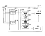
- FIG. 21 is a functional block diagram showing a configuration of the radio terminal UE4. Since the other radio terminals (radio terminals UE1 to UE3, UE5, UE6) are configured in the same manner as the radio terminal UE4, here, the radio terminal UE4 will be described as a representative of each radio terminal.
- the radio terminal UE4 includes antennas 2401 and 4022, a radio communication unit 2410, a control unit 2420, and a storage unit 2430.
- the radio communication unit 2410 includes a reception unit 2411 that receives a radio signal from the radio base station BS2 via the antennas 2401 and 4022, and a transmission unit 2412 that transmits the radio signal to the radio base station BS2 via the antennas 2401 and 4022.
- the radio signal received by the reception unit 2411 from the radio base station BS2 includes feedback information and control information.
- the transmission unit 2412 controls multi-antenna transmission based on the feedback information received by the reception unit 2411. Specifically, the transmission unit 2412 distributes the transmission signal to a plurality of layers according to RI, weights the transmission signal of each layer (hereinafter referred to as precoding), and follows the CQI for the transmission signal after precoding. Perform adaptive modulation and transmit power control.
- the control unit 2420 is configured by a CPU, for example, and controls various functions provided in the radio terminal UE4.
- the storage unit 2430 is configured by a memory, for example, and stores various types of information used for control in the radio terminal UE4.
- the control unit 2420 includes a control information acquisition unit 2421 and a transmission directivity control unit 2422.
- the control information acquisition unit 2421 acquires the control information for directing the null point of the directional beam with respect to the direction D1 of the radio base station BS1 that receives the second radio signal transmitted by the transmission unit 2412 as an interference signal. Parts.
- the transmission directivity control unit 2422 constitutes a control unit that controls the directional beam formed by the antennas 2401 and 2402 based on the PMI in the feedback information. Specifically, the directional beam formed by the antennas 2401 and 4022 can be directed in the direction D4 of the radio base station BS2 by precoding using a precoding matrix corresponding to the PMI fed back from the radio base station BS2. .
- the transmission directivity control unit 2422 directs the directional beam in the direction D4 of the radio base station BS2 based on the feedback information and the control information acquired by the control information acquisition unit 2421, and the radio base station BS1. A null point is directed in the direction D1.
- (3) Transmission Directivity Control in Wireless Terminal details of the transmission directivity control executed by the transmission directivity control unit 2422 will be described using FIG. 22 and FIG. Here, a case where a null point is directed in the direction D1 of the radio base station BS1 will be described as an example.
- the transmission directivity control unit 2422 selects a precoding matrix group that directs the null point in the direction D1 of the radio base station BS1 based on the control information.
- the precoding matrix group is a group including a plurality of precoding matrices having null points in the same direction, and is stored in advance in the storage unit 2430 of the radio terminal UE4.
- precoding matrix groups 1 to 8 having null points in different directions are illustrated.
- the precoding matrix group includes a plurality of precoding matrices each having a directional beam in a different direction, as shown in FIG.
- each of the precoding matrices 1 to 6 included in the precoding matrix group 1 has directional beams in six directions.
- the patterns of directional beams in the precoding matrices 1 to 6 are different.
- the transmission directivity control unit 2422 directs the radio base station BS2 in the direction D4 based on the PMI fed back from the radio base station BS2 from the precoding matrix group having a null point in the direction D1 of the radio base station BS1.
- a precoding matrix having a beam of directional characteristics is selected.
- the selected precoding matrix is applied to precoding in the transmission unit 2412 of the radio terminal UE4.
- FIG. 24 is an operation sequence diagram showing the operation of the radio communication system 2010A. In FIG. 24, only PMI is illustrated and described among feedback information (RI, PMI, CQI) according to the LTE standard.
- the operation sequence shown in FIG. 24 is repeatedly executed at predetermined time intervals (for example, in communication frame units).
- step S2101 the radio terminal UE4 transmits a second radio signal using the channel A.
- step S2104 the radio terminal UE1 transmits a first radio signal using the channel A.
- the receiving unit 2211 of the radio base station BS1 receives the first radio signal using the channel A as a desired signal, and receives the second radio signal using the channel A as an interference signal that interferes with the desired signal.
- step S2102 the radio terminal UE5 transmits a second radio signal using the channel B.
- step S2105 the radio terminal UE2 transmits a first radio signal using the channel B.
- the receiving unit 2211 of the radio base station BS1 receives the first radio signal using the channel B as a desired signal and receives the second radio signal using the channel B as an interference signal that interferes with the desired signal.
- step S2103 the radio terminal UE6 transmits a second radio signal using the channel C.
- step S2106 the radio terminal UE3 transmits a first radio signal using the channel C.
- the receiving unit 211 of the radio base station BS1 receives the first radio signal using the channel C as a desired signal, and receives the second radio signal using the channel C as an interference signal of the desired signal.
- step S2107 the reception unit 2211 of the radio base station BS1 performs channel estimation for estimating the channel response of the radio channel based on the pilot signal included in the first radio signal for each of the radio terminals UE1 to UE3.
- the identification information acquisition unit 2223 of the radio base station BS1 acquires the identification information from the second radio signals received by the reception unit 2211 from the radio terminals UE1 to UE3 according to the methods (a1) to (c1). .
- step S2108 the reception unit 2211 of the radio base station BS1 calculates a precoding matrix based on the estimated channel response, and acquires a PMI corresponding to the calculated precoding matrix.
- the arrival direction estimation unit 2221 of the radio base station BS1 estimates the arrival direction D1 of the second radio signal to the radio base station BS1.
- the interference information generation unit 2222 of the radio base station BS1 generates interference information based on the arrival direction D1.
- the arrival direction estimation unit 2221 estimates the arrival directions D2 and D3 of the second radio signal to the radio base station BS1.
- the interference information generation unit 2222 generates interference information based on the arrival directions D2 and D3.
- step S2110 the receiving unit 2211 of the radio base station BS1 equalizes the received signal (channel equalization) based on the estimated channel response, and decodes the equalized received signal.
- the decoded received signal is input to the control unit 2220 of the radio base station BS1.
- step S2111 the transmission unit 2212 of the radio base station BS1 transmits PMI as feedback information to the radio terminal UE1. Similarly, the transmitter 2212 transmits PMI to the radio terminal UE2 (step S2112), and transmits PMI to the radio terminal UE3 (step S2113).
- step S2115a the radio terminal UE1 selects a precoding matrix corresponding to the PMI received from the radio base station BS1.
- the radio terminal UE1 performs precoding using the selected precoding matrix when transmitting the first radio signal using the channel A to the radio base station BS1 next time.
- step S2115b the radio terminal UE2 selects a precoding matrix corresponding to the PMI received from the radio base station BS1.
- the radio terminal UE2 performs precoding using the selected precoding matrix when transmitting the first radio signal using the channel B to the radio base station BS1 next time.
- step S2115c the radio terminal UE3 selects a precoding matrix corresponding to the PMI received from the radio base station BS1.
- the radio terminal UE3 performs precoding using the selected precoding matrix when transmitting the first radio signal using the channel C to the radio base station BS1 next time.
- step S2114 the wired communication unit 2240 of the radio base station BS1 transmits the interference information generated by the interference information generation unit 2222 and the specification information acquired by the specification information acquisition unit 2223 to the control device 2100A.
- the receiving unit 2111 of the control device 2100A receives interference information and identification information.
- the base station specifying unit 2121 of the control apparatus 2100A uses the specifying information received by the receiving unit 2111 according to the methods (a2) to (c2) above, and the radio base station to which the interference source terminal is connected Specify BS2.
- the transmission unit 2112 of the control apparatus 2100A transmits interference information and identification information to the radio base station BS2 identified by the base station identification unit 2121.
- the wired communication unit 2340 of the radio base station BS2 receives interference information and identification information.
- the receiving unit 2311 of the radio base station BS2 calculates a precoding matrix for each of the radio terminals UE4 to UE6 to which the radio base station BS2 is connected, and acquires a PMI corresponding to the calculated precoding matrix.
- the interference information acquisition unit 2321 of the radio base station BS2 acquires the interference information received by the wired communication unit 2340 from the control device 2100A.
- the terminal identification unit 2322 of the radio base station BS2 uses the identification information received by the wired communication unit 2340 from the control device 2100A, and is connected to the radio base station BS2 in accordance with the methods (a3) and (b3).
- the interference source terminal is identified from among the wireless terminals.
- the radio terminals UE4 to UE6 are specified as interference source terminals.
- step S2119a the transmission unit 2312 of the radio base station BS2 transmits PMI as feedback information and control information to the radio terminal UE4.
- step S2119b the transmission unit 2312 transmits PMI as feedback information and control information to the radio terminal UE5.
- step S2119c the transmission unit 2312 transmits PMI as feedback information and control information to the radio terminal UE6.
- the receiving unit 2411 of each of the radio terminals UE4 to UE6 receives PMI and control information.
- the transmission directivity control unit 2422 of the radio terminal UE4 directs a directional beam in the direction D4 of the radio base station BS2 based on the PMI and control information received by the reception unit 2411, and the radio base station BS1.
- the transmission unit 2412 is controlled so that the null point is directed in the direction D1.
- the transmission directivity control unit 2422 of the radio terminal UE4 directs the directional beam in the direction D4 of the radio base station BS2 from the precoding matrix group that directs the null point in the direction D1 of the radio base station BS1.
- Select a precoding matrix Select a precoding matrix.
- the transmitter 2412 of the radio terminal UE4 performs precoding using the selected precoding matrix when transmitting the second radio signal using the channel A next time.
- step S2120b the transmission directivity control unit 2422 of the radio terminal UE5, based on the PMI and control information received by the reception unit 2411, a precoding matrix group that directs the null point in the direction D2 of the radio base station BS1.
- the precoding matrix for directing the directional beam in the direction D5 of the radio base station BS2 is selected from the above.
- the transmitter 2412 of the radio terminal UE5 performs precoding using the selected precoding matrix when transmitting the second radio signal using the channel B next time.
- step S2120b the transmission directivity control unit 2422 of the radio terminal UE6, based on the PMI and control information received by the reception unit 2411, out of the precoding matrix group that directs the null point in the direction D3 of the radio base station BS1, A precoding matrix for directing a directional beam in the direction D6 of the radio base station BS2 is selected.
- the transmitter 2412 of the radio terminal UE6 performs precoding using the selected precoding matrix when transmitting the second radio signal using the channel C next time.
- the radio base station BS1 when the radio base station BS1 receives the second radio signal from the radio terminals UE4 to UE6 as an interference signal, the radio terminals UE4 to UE6 A null point is directed in the direction D1 to D3 of the base station BS1. For this reason, it can avoid that radio base station BS1 receives a 2nd radio signal (interference signal), and the communication quality in radio base station BS1 can fully be improved.
- interference signal interference signal
- the transmission directivity control unit 2422 of the radio terminals UE4 to UE6 directs a null point in the directions D1 to D3 of the radio base station BS1 based on the PMI and control information received from the radio base station BS2.
- the directional beam is directed in the directions D4 to D6 of the radio base station BS2. Therefore, the communication quality in the radio base station BS2 can be kept good while sufficiently improving the communication quality in the radio base station BS1.
- the base station specifying unit 2121 of the control device 2100A specifies the radio base station BS2 to which the interference source terminal is connected in accordance with the methods (a2) to (c2).
- the terminal specifying unit 2322 of the radio base station BS2 specifies an interference source terminal according to the methods (a3) and (b3).
- the control information acquisition unit 2421 of the radio terminals UE4 to UE6 acquires coefficient or angle information indicating the arrival direction, or PMI from the radio base station BS2 as interference information and control information. It was.
- the rough direction of the radio base station BS1 can be specified from the position of the radio base station BS1, information indicating the position of the radio base station BS1 may be used as interference information and control information. Since the installation position of the radio base station BS1 is fixed, the position information of the radio base station BS1 can be held in advance in the radio base station BS1 or the control device 2100A.
- the transmission directivity control unit 2422 of the radio terminals UE4 to UE6 can identify the direction of the radio base station BS1 from the location of the radio base station BS1. Good.
- the control information acquisition unit 2421 uses the GPS or the like provided in each of the radio terminals UE4 to UE6 to obtain the position information of each of the radio terminals UE4 to UE6. Furthermore, you may acquire.
- the detailed direction of the radio base station BS1 can be specified from the position of each of the radio terminals UE4 to UE6 and the position of the radio base station BS1.
- the control information acquisition unit 2421 of the radio terminals UE4 to UE6 acquires coefficient or angle information indicating the arrival direction, or PMI from the radio base station BS2 as interference information and control information.
- the control information may be acquired by other methods.
- the control information acquisition unit 421 estimates the arrival direction of the downlink radio signal and indicates the estimated arrival direction. Information may be acquired as control information.
- the transmission directivity control unit 422 of the radio terminals UE4 to UE6 may specify the direction of the radio base station BS1 from the arrival direction of the downlink radio signal.
- the control device 2100A is provided separately for the radio base station BS1 and the radio base station BS2. In the fourth embodiment, a mode in which the control device 2100A is included in the radio base station BS1 will be described.
- FIG. 25 is an overall configuration diagram of a radio communication system 2010B according to the fourth embodiment.
- the radio base station BS1 ′ has the function of the control device 2100B.
- the control unit 2220 of the radio base station BS1 ′ includes a base station specifying unit 2224 that specifies a radio base station to which the interference source terminal is connected.
- the function of the base station specifying unit 2224 is the same as the function of the base station specifying unit 2121 described in the third embodiment.
- FIG. 27 is an operation sequence diagram showing the operation of the radio communication system 2010B. In FIG. 27, each process up to step S2213 and each process after step S2218 are the same as those in the third embodiment, so the processes in steps S2214 and S2217 will be described.
- step S2214 the base station specifying unit 2224 of the radio base station BS1 ′ specifies the radio base station BS2 to which the interference source terminal is connected according to the methods (a2) to (c2) using the specifying information. .
- step S2217 the wired communication unit 2240 of the radio base station BS1 ′ transmits interference information and identification information to the radio base station BS2 identified by the base station identification unit 2224.
- the wired communication unit 2340 of the radio base station BS2 receives interference information and identification information.
- the second radio signal when the radio base station BS1 receives the second radio signal, the second radio signal is regarded as an interference signal. However, the second radio signal less than a predetermined reception level is used. May be allowed. In this case, when the radio base station BS1 receives the second radio signal and the reception level of the second radio signal is equal to or higher than a predetermined reception level, the radio base station BS1 considers the second radio signal as an interference signal. Become.
- the FDD scheme is adopted as a duplex scheme, but a time division duplex (TDD) scheme may be adopted instead of the FDD scheme.
- TDD time division duplex
- the case where there are two transmission antennas and four reception antennas in uplink communication (2 ⁇ 4 MIMO) has been described.
- uplink communication when there is one receiving antenna, that is, a multi-antenna transmission with multiple inputs and one output (MISO) may be implemented.
- MISO multi-antenna transmission with multiple inputs and one output
- a plurality of radio terminals are connected to each of the radio base stations BS1 and BS2.
- one radio terminal may be connected to each of the radio base stations BS1 and BS2.
- the wireless communication systems 2010A and 2010B based on the LTE standard have been described.
- the wireless communication system based on the WiMAX standard (IEEE802.16) and 3GPP2 are not limited to the LTE standard.
- the present invention can be applied to UMB (Ultra Mobile Mobile Broadband) standards.
Abstract
L'invention concerne une station de base radio (BS1) comprenant : une unité de transmission (1412) qui transmet, par l'intermédiaire d'une pluralité d'antennes de transmission, un signal radio à un premier terminal radio ayant une pluralité d'antennes de réception ; une unité de régulation de directivité de transmission (1422) qui régule des faisceaux directionnels, qui sont formés par les antennes de transmission, sur la base des informations de retour qui sont renvoyées depuis le premier terminal radio ; et une unité d'acquisition d'informations (1421) qui acquiert des informations de régulation à utiliser pour diriger les points nuls des faisceaux directionnels vers un second terminal radio qui reçoit, comme signal d'interférence, le signal radio susdit pendant la communication avec une autre station de base. L'unité de régulation de directivité de transmission (1422) dirige, en fonction des informations de retour et des informations de régulation, les faisceaux directionnels vers le premier terminal radio et les points nuls susdits vers le second terminal radio.
Priority Applications (1)
| Application Number | Priority Date | Filing Date | Title |
|---|---|---|---|
| US13/145,766 US8934559B2 (en) | 2009-01-22 | 2010-01-22 | Radio base station, radio terminal, and radio communication method |
Applications Claiming Priority (4)
| Application Number | Priority Date | Filing Date | Title |
|---|---|---|---|
| JP2009-012331 | 2009-01-22 | ||
| JP2009012331A JP5244631B2 (ja) | 2009-01-22 | 2009-01-22 | 無線装置および無線通信方法 |
| JP2009017399A JP5302024B2 (ja) | 2009-01-28 | 2009-01-28 | 無線端末及び無線通信方法 |
| JP2009-017399 | 2009-01-28 |
Publications (1)
| Publication Number | Publication Date |
|---|---|
| WO2010084937A1 true WO2010084937A1 (fr) | 2010-07-29 |
Family
ID=42355989
Family Applications (1)
| Application Number | Title | Priority Date | Filing Date |
|---|---|---|---|
| PCT/JP2010/050757 WO2010084937A1 (fr) | 2009-01-22 | 2010-01-22 | Station de base radio, terminal radio et procédé de communication sans fil |
Country Status (2)
| Country | Link |
|---|---|
| US (1) | US8934559B2 (fr) |
| WO (1) | WO2010084937A1 (fr) |
Cited By (4)
| Publication number | Priority date | Publication date | Assignee | Title |
|---|---|---|---|---|
| WO2012114141A1 (fr) | 2011-02-22 | 2012-08-30 | Nokia Corporation | Codage réseau par formation de faisceau |
| CN103299668A (zh) * | 2011-01-07 | 2013-09-11 | 株式会社Ntt都科摩 | 无线基站装置、用户终端以及无线通信方法 |
| JP2014507888A (ja) * | 2011-01-28 | 2014-03-27 | ▲ホア▼▲ウェイ▼技術有限公司 | ハンドオーバ方法、基地局、およびシステム |
| JP2015524637A (ja) * | 2012-08-08 | 2015-08-24 | テレフオンアクチーボラゲット エル エム エリクソン(パブル) | マルチ標準無線アクセスネットワークのための無線アクセス技術間干渉協調 |
Families Citing this family (18)
| Publication number | Priority date | Publication date | Assignee | Title |
|---|---|---|---|---|
| US8995359B2 (en) * | 2010-04-05 | 2015-03-31 | Qualcomm Incorporated | Method and apparatus to facilitate support for multi-radio coexistence |
| JP5902817B2 (ja) | 2011-09-30 | 2016-04-13 | 京セラ株式会社 | 小セルの上りリンクの干渉を緩和するシステム及び方法 |
| WO2013089191A1 (fr) * | 2011-12-13 | 2013-06-20 | 京セラ株式会社 | Terminal mobile, système de communication sans fil et procédé de communication sans fil |
| US10090901B2 (en) * | 2012-02-07 | 2018-10-02 | Motorola Mobility Llc | Method and apparatus for optimizing antenna precoder selection with coupled antennas |
| US8995592B2 (en) * | 2012-05-10 | 2015-03-31 | Futurewei Technologies, Inc. | Signaling to support advanced wireless receivers and related devices and methods |
| US9641232B2 (en) | 2012-12-07 | 2017-05-02 | Sharp Kabushiki Kaisha | Transmission device and wireless communication method that provides precoded transmission data to first and second reception devices |
| EP2974068B1 (fr) * | 2013-03-11 | 2018-01-10 | Telefonaktiebolaget LM Ericsson (publ) | Procédé dans un noeud de réseau et noeud de réseau pour commander une communication entre une station de base radio et des équipements utilisateur dans un système de communication sans fil |
| EP3065441A4 (fr) * | 2013-10-29 | 2017-06-07 | Kyocera Corporation | Procédé de commande de communication et station de base |
| US9578644B2 (en) * | 2014-09-26 | 2017-02-21 | Mediatek Inc. | Beam misalignment detection for wireless communication system with beamforming |
| JPWO2016121251A1 (ja) | 2015-01-29 | 2017-11-09 | ソニー株式会社 | 装置及び方法 |
| JP6437161B2 (ja) | 2016-05-18 | 2018-12-12 | 三菱電機株式会社 | 送信局、制御局、受信局、データ伝送システムおよびデータ伝送方法 |
| US10455601B2 (en) * | 2016-11-17 | 2019-10-22 | Telefonaktiebolaget Lm Ericsson (Publ) | Co-scheduling of wireless devices |
| MX2019014131A (es) * | 2017-06-02 | 2020-02-07 | Sony Corp | Aparato de comunicacion y sistema de comunicacion. |
| JP7102767B2 (ja) * | 2018-02-19 | 2022-07-20 | 富士通株式会社 | 送信方法、基地局装置及び無線通信システム |
| EP3861824A1 (fr) * | 2018-10-05 | 2021-08-11 | Nokia Technologies Oy | Réutilisation spatiale pour réseau sans fil |
| WO2020119910A1 (fr) | 2018-12-13 | 2020-06-18 | Telefonaktiebolaget Lm Ericsson (Publ) | Adaptation de transmission à formation de faisceau |
| WO2021155926A1 (fr) * | 2020-02-06 | 2021-08-12 | Telefonaktiebolaget Lm Ericsson (Publ) | Gestion de dégradation de performance entre des noeuds de réseau d'accès radio |
| JP2022130910A (ja) | 2021-02-26 | 2022-09-07 | 富士通株式会社 | 無線通信装置、及び、ビーム制御方法 |
Citations (8)
| Publication number | Priority date | Publication date | Assignee | Title |
|---|---|---|---|---|
| JP2003008494A (ja) * | 2001-06-22 | 2003-01-10 | Kddi Corp | 無線基地局 |
| JP2003115792A (ja) * | 2001-10-03 | 2003-04-18 | Kyocera Corp | アダプティブアレイ基地局 |
| JP2004297483A (ja) * | 2003-03-27 | 2004-10-21 | Kyocera Corp | 移動局、通信制御方法 |
| JP2007312205A (ja) * | 2006-05-19 | 2007-11-29 | Matsushita Electric Ind Co Ltd | 基地局装置およびアレイアンテナ制御方法 |
| JP2008160380A (ja) * | 2006-12-22 | 2008-07-10 | Nec Corp | セル間干渉抑圧方法、無線基地局、ユーザ端末 |
| JP2008536342A (ja) * | 2005-04-14 | 2008-09-04 | 松下電器産業株式会社 | 無線受信装置、無線送信装置、無線通信システム、無線受信方法、無線送信方法および無線通信方法 |
| JP2008236222A (ja) * | 2007-03-19 | 2008-10-02 | Hitachi Communication Technologies Ltd | 無線通信方法 |
| JP2008252359A (ja) * | 2007-03-29 | 2008-10-16 | Kyocera Corp | 通信制御方法、通信システムおよび通信制御装置 |
Family Cites Families (2)
| Publication number | Priority date | Publication date | Assignee | Title |
|---|---|---|---|---|
| US6859503B2 (en) * | 2001-04-07 | 2005-02-22 | Motorola, Inc. | Method and system in a transceiver for controlling a multiple-input, multiple-output communications channel |
| JP4578346B2 (ja) * | 2005-07-25 | 2010-11-10 | 株式会社エヌ・ティ・ティ・ドコモ | 無線制御装置および通信方法 |
-
2010
- 2010-01-22 US US13/145,766 patent/US8934559B2/en active Active
- 2010-01-22 WO PCT/JP2010/050757 patent/WO2010084937A1/fr active Application Filing
Patent Citations (8)
| Publication number | Priority date | Publication date | Assignee | Title |
|---|---|---|---|---|
| JP2003008494A (ja) * | 2001-06-22 | 2003-01-10 | Kddi Corp | 無線基地局 |
| JP2003115792A (ja) * | 2001-10-03 | 2003-04-18 | Kyocera Corp | アダプティブアレイ基地局 |
| JP2004297483A (ja) * | 2003-03-27 | 2004-10-21 | Kyocera Corp | 移動局、通信制御方法 |
| JP2008536342A (ja) * | 2005-04-14 | 2008-09-04 | 松下電器産業株式会社 | 無線受信装置、無線送信装置、無線通信システム、無線受信方法、無線送信方法および無線通信方法 |
| JP2007312205A (ja) * | 2006-05-19 | 2007-11-29 | Matsushita Electric Ind Co Ltd | 基地局装置およびアレイアンテナ制御方法 |
| JP2008160380A (ja) * | 2006-12-22 | 2008-07-10 | Nec Corp | セル間干渉抑圧方法、無線基地局、ユーザ端末 |
| JP2008236222A (ja) * | 2007-03-19 | 2008-10-02 | Hitachi Communication Technologies Ltd | 無線通信方法 |
| JP2008252359A (ja) * | 2007-03-29 | 2008-10-16 | Kyocera Corp | 通信制御方法、通信システムおよび通信制御装置 |
Cited By (7)
| Publication number | Priority date | Publication date | Assignee | Title |
|---|---|---|---|---|
| CN103299668A (zh) * | 2011-01-07 | 2013-09-11 | 株式会社Ntt都科摩 | 无线基站装置、用户终端以及无线通信方法 |
| CN103299668B (zh) * | 2011-01-07 | 2016-08-24 | 株式会社Ntt都科摩 | 无线基站装置、以及无线通信方法 |
| JP2014507888A (ja) * | 2011-01-28 | 2014-03-27 | ▲ホア▼▲ウェイ▼技術有限公司 | ハンドオーバ方法、基地局、およびシステム |
| US8918107B2 (en) | 2011-01-28 | 2014-12-23 | Huawei Technologies Co., Ltd. | Handover method, base station and system |
| WO2012114141A1 (fr) | 2011-02-22 | 2012-08-30 | Nokia Corporation | Codage réseau par formation de faisceau |
| EP2678950A4 (fr) * | 2011-02-22 | 2017-06-28 | Nokia Technologies Oy | Codage réseau par formation de faisceau |
| JP2015524637A (ja) * | 2012-08-08 | 2015-08-24 | テレフオンアクチーボラゲット エル エム エリクソン(パブル) | マルチ標準無線アクセスネットワークのための無線アクセス技術間干渉協調 |
Also Published As
| Publication number | Publication date |
|---|---|
| US8934559B2 (en) | 2015-01-13 |
| US20110281600A1 (en) | 2011-11-17 |
Similar Documents
| Publication | Publication Date | Title |
|---|---|---|
| WO2010084937A1 (fr) | Station de base radio, terminal radio et procédé de communication sans fil | |
| WO2010084936A1 (fr) | Système de communication sans fil, terminal radio, station de base radio, appareil de régulation et procédé de communication sans fil | |
| JP5244631B2 (ja) | 無線装置および無線通信方法 | |
| JP6400001B2 (ja) | チャネル状態情報フィードバックレポーティングのための方法及び装置 | |
| KR101241910B1 (ko) | 다중 셀 환경에서 사운딩 채널을 이용한 협력적 mimo 기법 | |
| US10148332B2 (en) | System and method for multi-level beamformed non-orthogonal multiple access communications | |
| JP5406919B2 (ja) | 無線通信システムおよび統合基地局 | |
| JP5682710B2 (ja) | Mimo通信ネットワークにおいて使用される方法及びユーザ装置 | |
| US8457008B2 (en) | Method of transmitting feedback information for performing collaborative MIMO | |
| Li et al. | Advancement of MIMO technology in WiMAX: from IEEE 802.16 d/e/j to 802.16 m | |
| KR20170091664A (ko) | 부분 프리코딩 csi-rs 및 csi 피드백을 위한 다운링크 시그널링 방법 및 장치 | |
| WO2010048745A1 (fr) | Procédé et appareil de communication collaborative à multiples stations base à technologie mimo | |
| JP2013516799A (ja) | ダウンリンクマルチアンテナマルチ基地局干渉協調方法と基地局 | |
| KR102306100B1 (ko) | Mumimo 간섭 채널 네트워크 환경에서의 간섭정렬 송수신 신호처리 장치 및 방법 | |
| Tolli et al. | Distributed coordinated transmission with forward-backward training for 5G radio access | |
| AU2013247558A2 (en) | Method and apparatus for transmitting and receiving a feedback signal in a mobile communication system | |
| US20210258977A1 (en) | Sdma carrier sharing | |
| JP5244630B2 (ja) | 無線通信システム、無線端末、制御装置、及び無線通信方法 | |
| KR20180009776A (ko) | 무선 통신 제어 방법, 무선 통신 시스템, 수신 장치 및 송신 장치 | |
| CN110011706B (zh) | 一种优化协作传输的方法及装置 | |
| CN105745845A (zh) | 为了减小量化噪声使用自相关矩阵进行用于基于码本的mimo波束赋形的预编码的用户设备和方法 | |
| JP5302024B2 (ja) | 無線端末及び無線通信方法 | |
| JP5518230B2 (ja) | 無線端末およびプロセッサ | |
| JP5232031B2 (ja) | 無線通信システム、無線基地局、制御装置、及び無線通信方法 |
Legal Events
| Date | Code | Title | Description |
|---|---|---|---|
| 121 | Ep: the epo has been informed by wipo that ep was designated in this application |
Ref document number: 10733544 Country of ref document: EP Kind code of ref document: A1 |
|
| WWE | Wipo information: entry into national phase |
Ref document number: 13145766 Country of ref document: US |
|
| NENP | Non-entry into the national phase |
Ref country code: DE |
|
| 122 | Ep: pct application non-entry in european phase |
Ref document number: 10733544 Country of ref document: EP Kind code of ref document: A1 |